EP4517427A1 - Lichtquellenvorrichtung - Google Patents
Lichtquellenvorrichtung Download PDFInfo
- Publication number
- EP4517427A1 EP4517427A1 EP23811591.9A EP23811591A EP4517427A1 EP 4517427 A1 EP4517427 A1 EP 4517427A1 EP 23811591 A EP23811591 A EP 23811591A EP 4517427 A1 EP4517427 A1 EP 4517427A1
- Authority
- EP
- European Patent Office
- Prior art keywords
- radiation
- section
- light source
- raw material
- source apparatus
- Prior art date
- Legal status (The legal status is an assumption and is not a legal conclusion. Google has not performed a legal analysis and makes no representation as to the accuracy of the status listed.)
- Pending
Links
Images



Classifications
-
- H—ELECTRICITY
- H05—ELECTRIC TECHNIQUES NOT OTHERWISE PROVIDED FOR
- H05G—X-RAY TECHNIQUE
- H05G2/00—Apparatus or processes specially adapted for producing X-rays, not involving X-ray tubes, e.g. involving generation of a plasma
- H05G2/001—Production of X-ray radiation generated from plasma
- H05G2/002—Supply of the plasma generating material
- H05G2/0025—Systems for collecting the plasma generating material after the plasma generation
-
- G—PHYSICS
- G03—PHOTOGRAPHY; CINEMATOGRAPHY; ANALOGOUS TECHNIQUES USING WAVES OTHER THAN OPTICAL WAVES; ELECTROGRAPHY; HOLOGRAPHY
- G03F—PHOTOMECHANICAL PRODUCTION OF TEXTURED OR PATTERNED SURFACES, e.g. FOR PRINTING, FOR PROCESSING OF SEMICONDUCTOR DEVICES; MATERIALS THEREFOR; ORIGINALS THEREFOR; APPARATUS SPECIALLY ADAPTED THEREFOR
- G03F7/00—Photomechanical, e.g. photolithographic, production of textured or patterned surfaces, e.g. printing surfaces; Materials therefor, e.g. comprising photoresists; Apparatus specially adapted therefor
- G03F7/70—Microphotolithographic exposure; Apparatus therefor
- G03F7/70008—Production of exposure light, i.e. light sources
- G03F7/70033—Production of exposure light, i.e. light sources by plasma extreme ultraviolet [EUV] sources
-
- G—PHYSICS
- G03—PHOTOGRAPHY; CINEMATOGRAPHY; ANALOGOUS TECHNIQUES USING WAVES OTHER THAN OPTICAL WAVES; ELECTROGRAPHY; HOLOGRAPHY
- G03F—PHOTOMECHANICAL PRODUCTION OF TEXTURED OR PATTERNED SURFACES, e.g. FOR PRINTING, FOR PROCESSING OF SEMICONDUCTOR DEVICES; MATERIALS THEREFOR; ORIGINALS THEREFOR; APPARATUS SPECIALLY ADAPTED THEREFOR
- G03F7/00—Photomechanical, e.g. photolithographic, production of textured or patterned surfaces, e.g. printing surfaces; Materials therefor, e.g. comprising photoresists; Apparatus specially adapted therefor
- G03F7/70—Microphotolithographic exposure; Apparatus therefor
- G03F7/708—Construction of apparatus, e.g. environment aspects, hygiene aspects or materials
- G03F7/70908—Hygiene, e.g. preventing apparatus pollution, mitigating effect of pollution or removing pollutants from apparatus
- G03F7/70916—Pollution mitigation, i.e. mitigating effect of contamination or debris, e.g. foil traps
-
- H—ELECTRICITY
- H05—ELECTRIC TECHNIQUES NOT OTHERWISE PROVIDED FOR
- H05G—X-RAY TECHNIQUE
- H05G2/00—Apparatus or processes specially adapted for producing X-rays, not involving X-ray tubes, e.g. involving generation of a plasma
- H05G2/001—Production of X-ray radiation generated from plasma
- H05G2/009—Auxiliary arrangements not involved in the plasma generation
- H05G2/0094—Reduction, prevention or protection from contamination; Cleaning
-
- H—ELECTRICITY
- H05—ELECTRIC TECHNIQUES NOT OTHERWISE PROVIDED FOR
- H05G—X-RAY TECHNIQUE
- H05G2/00—Apparatus or processes specially adapted for producing X-rays, not involving X-ray tubes, e.g. involving generation of a plasma
- H05G2/001—Production of X-ray radiation generated from plasma
- H05G2/008—Production of X-ray radiation generated from plasma involving an energy-carrying beam in the process of plasma generation
- H05G2/0082—Production of X-ray radiation generated from plasma involving an energy-carrying beam in the process of plasma generation the energy-carrying beam being a laser beam
Definitions
- the DPP method (LDP method) light source apparatus or the LPP method light source apparatus can be used as an EUV light source apparatus that generates EUV light in the soft X-ray region.
- the DPP method (LDP method) light source apparatus since the DPP method (LDP method) light source apparatus eventually uses discharge between the electrodes to generate plasma, debris associated with EUV raw materials is likely to generate.
- the LPP method light source apparatus is designed to set a minute droplet made of tin, which is EUV raw material, to be a target and focus a laser beam for excitation onto the target, thus making the configuration of the light source apparatus complex.
- Patent Literature 1 discloses a method in which a liquid target material for generating X-rays is applied to disk-shaped rotation bodies and the applied liquid material is irradiated with an energy beam (laser beam) to generate X-rays. This method is capable of obtaining high-brightness X-rays with a relatively simple configuration.
- a case in which the method described in Patent Literature 1 is applied to an EUV light source apparatus corresponds to the LPP method.
- this method eliminates the need for supplying the EUV raw material in liquid in a form of a droplet.
- this method is capable of readily supplying the EUV material, and enables the liquid EUV material to be reliably irradiated with a laser beam, obtaining EUV radiation using an apparatus with a relatively simple configuration.
- Patent Literature 1 Japanese Patent No. 6658324
- the radiation (X-ray or EUV) raw material is irradiated with an energy beam (electron beam or laser beam) to generate plasma, from which radiation is extracted, however, debris is generated during plasma generation as is similar to the DPP method and the LDP method.
- an energy beam electron beam or laser beam
- debris is generated during plasma generation as is similar to the DPP method and the LDP method.
- liquid raw material on a flat surface is vaporized by an energy beam, debris constituted by liquid raw material is released the most in the normal direction of the flat surface.
- the normal direction different from the direction in which the radiation is extracted, it is possible to suppress the entry of debris in the direction in which the radiation is extracted.
- a light source apparatus includes a disk-shaped rotation body, a raw material supply mechanism, a chamber body, and a foil trap.
- the chamber body includes a beam introduction section that introduces the energy beam, a radiation extraction section that extracts radiation from the plasma that has been generated, and a plasma generation section that accommodates the rotation body.
- the front surface of the rotation body may be a plane perpendicular to a rotation axis of the rotation body.
- the shaft member is disposed along a direction parallel to the rotation axis of the rotation body.
- the foil trap may further include a cover member that has a space section that accommodates the plurality of foils in a rotatable manner.
- the cover member includes a first opening that allows the radiation to enter the space section, and a second opening that is communicated with the space section and allows the radiation that has been incident through the first opening to be emitted toward the radiation extraction section.
- the light source apparatus may further include a second gas supply section that forms a flow of air flowing across a direction of an axis of the shaft member, a direction of the optical axis of the energy beam, and a direction of the principal axis of the radiation.
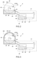
- FIG. 1 is a schematic diagram illustrating a configuration example of a light source apparatus according to an embodiment of the present invention.
- the X direction denotes the left-right direction (the positive side of the X axis is the right side and the negative side is the left side)
- the Y direction denotes the front-rear direction (the positive side of the Y axis is the front side and the negative side is the rear side)
- the Z direction denotes the height direction (the positive side of the Z axis is the upper side, and the negative side is the lower side).
- the application of the present technology is not limited to the direction in which the light source apparatus 1 is used.
- the light source apparatus 1 includes an enclosure 2, a vacuum chamber 3, an energy beam incident chamber 4, a radiation emission chamber 5, a raw material supply mechanism 6, and a controller 7.
- the radiation R is set to allow its emission axis EA to pass through the emission hole 8 in the front face and extend in the Y direction (front-rear direction).
- the radiation R such as X-rays and EUV light is extracted along the emission axis EA and emitted through the emission hole 8 toward the front side.
- the energy beam EB is also set to allow its incident axis IA to extend from the incident hole 9 on the right side face toward the rear side at an oblique angle to the left.
- the chamber body 14 includes a cylindrical-shaped outer protrusion 15 protruding toward the front side of the chamber body 14, and a cylindrical-shaped inner protrusion 17 protruding inward from the inner circumferential face of the chamber body 14.
- the outer protrusion 15 constitutes the emission chamber 5
- the inner protrusion 17 constitutes the incident chamber 4.
- the emission chamber 5, the outer protrusion 15, and the like constitute the "radiation extraction section” that extracts and emits radiation from the generated plasma.
- the emission chamber 5 is disposed on the emission axis EA of the radiation R.
- an emission hole 18 is formed in the front face of the chamber body 14.
- the emission hole 18 is formed along the emission axis EA of the radiation R, and in line with the emission hole 8 in the front face of the enclosure 2.
- the outer protrusion 15 is configured to protrude toward the front side from the circumferential edge of the emission hole 18 in the chamber body 14.
- the outer protrusion 15 is configured to protrude toward the front side more than the emission hole 8 of the enclosure 2 while being inscribed in the emission hole 8 of the enclosure 2.
- the space surrounded by the outer protrusion 15 serves as the emission chamber 5.
- the outer protrusion itself which is the member constituting the emission chamber 5, can also be referred to as emission chamber.
- the outer protrusion 15 may be integrally formed with the chamber body 14; however, it may be separately formed and then connected to the chamber body 14.
- the emission chamber 5 is configured to have a cone shape with its central axis being aligned with the emission axis EA of the radiation R.
- the emission chamber 5 is configured to have a large cross-sectional area at its center portion in the direction of the emission axis EA of the radiation R, and have the cross-sectional area being decreased toward the front and rear ends thereof. In other words, the emission chamber 5 is shaped to taper toward the front and rear ends thereof.
- An incident window 19 is formed in the right-front corner of the chamber body 14.
- the incident window 19 is formed along the incident axis IA of the energy beam EB, and in line with the incident hole 9 in the right side face of the enclosure 2.
- the inner protrusion 17 is configured to protrude inside the right-front corner of the chamber body 14 along the incident axis IA of the energy beam EB from a position surrounding the incident window 19.
- the space surrounded by the inner protrusion 17 serves as the incident chamber 4.
- the inner protrusion 17 may be integrally formed with the chamber body 14; however, it may be separately formed and then connected to the chamber body 14.
- the incident chamber 4 is configured to have a cone shape with its central axis being aligned with the incident axis IA of the energy beam EB.
- the incident chamber 4 is configured to have a cross-sectional area being decreased toward its end inside the chamber body 14 in the direction of the incident axis IA of the energy beam EB.
- the incident chamber 4 has a tapered shape toward the end thereof inside the chamber body 14.
- the vacuum chamber 3 In the internal space of the chamber body 14, the space excluding the internal space of the inner protrusion 17, which serves as the incident chamber 4, serves as the vacuum chamber 3.
- the components themselves constituting the vacuum chamber 3 can also be referred to as the vacuum chamber.
- Rotating the rotary window 27 makes it possible to increase the substantial area of the beam transmission area of the rotary window 27, achieving a longer service life of the rotary window 27 and reducing the frequency of replacement of the rotary window 27.
- a filter film 35 is provided between the emission chamber 5 and the application chamber 30.
- the filter film 35 serves to physically separate the plasma generation area 21 in the vacuum chamber 3 from the application chamber 30 (physically separate the space), preventing the scattered plasma raw material 23 and debris from entering the application chamber 30.
- the filter film 35 is made of a material that transmits the radiation R generated in the plasma generation area 21.
- the filter film 35 is constituted by, for example, a beryllium thin film that has a very high transmittance for X-rays.
- the filter film 35 is made of zirconium (Zr), for example.
- the present embodiment is provided with a gas nozzle 37 at the rear side of the incident chamber 4 in a manner that extends in the left-right direction.
- the gas nozzle 37 is disposed in the right side face of the chamber body 14 via a seal member or the like.
- the gas nozzle 37 is connected to a gas supply device, illustration of which is omitted in the figure, and supplies gas to the chamber body 14.
- the gas nozzle 37 corresponds to a second gas supply section that will be described later and blows gas from the right side of the between-axes area located between the incident axis IA and the emission axis EA toward the left side thereof along the left-right direction. This makes it possible to move debris that is emitted from the plasma P in a direction away from the incident axis IA and the emission axis EA.
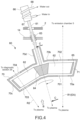
- FIG. 2 is a schematic diagram illustrating a configuration example of the raw material supply mechanism 6.
- FIG. 2 illustrates the rotation body 22 and the container 24 viewed from the direction of arrow A in FIG. 1 . Accordingly, the side of a front surface 22a of the rotation body 22 is illustrated in FIG. 2 .
- the raw material supply mechanism 6 includes the disk-shaped rotation body 22, the container 24, a motor 38, a skimmer 40, and a plasma raw material circulator 41.
- the rotation body 22 is made of a high-melting-point metal such as tungsten (W), molybdenum (Mo), or tantalum (Ta).
- tungsten W
- Mo molybdenum
- Ta tantalum
- the X-ray raw material is a metal that is in the form of liquid at room temperature.
- examples of the X-ray raw material include gallium (Ga), and gallium alloys such as Galinstan (registered trademark), which is a eutectic alloy of gallium, indium (In), and tin (Sn).
- EUV raw materials are used as the plasma raw material 23.
- the raw material that emits EUV light include tin (Sn) and lithium (Li) in the form of liquid. Since Sn and Li are solid at room temperature, the container 24 is provided with a temperature control means, illustration of which is omitted in the figure. For example, when the EUV raw material is Sn, the container 24 is maintained at a temperature above the melting point of Sn.
- the rotation shaft 39 of the motor 38 is connected to the center of the back surface 22b of the rotation body 22.
- the controller 7 controls the operation of the motor 38, which allows the rotation body 22 to rotate via the rotation shaft 39.
- the rotation shaft 39 is disposed to extend in a direction orthogonal to the front surface 22a of the rotation body 22. Hence, the rotation body 22 rotates with the direction orthogonal to the front surface 22a as a rotation direction.
- the rotation shaft 39 passes through the through-hole 10 in the enclosure 2 and is introduced into the vacuum chamber 3 via a mechanical seal 42.
- the mechanical seal 42 allows the rotation shaft 39 to rotate while maintaining a reduced-pressure atmosphere in the vacuum chamber 3.
- the rotation body 22 rotates around the rotation shaft 39 in a state in which a part of the lower side of the rotation body 22 is immersed in the plasma raw material 23 stored in the container 24.
- This causes the plasma raw material 23 to be pulled up from the raw material storage portion of the container 24 in a manner that the plasma raw material 23 spreads over the front surface 22a of the rotation body 22 due to its wettability with the front surface 22a of the rotation body 22, and to be transported.
- the motor 38 and the rotation shaft 39 serve as a raw material supply section that applies the raw material to at least a part of the front surface 22a of the rotation body 22.
- the incident area 25 onto which the energy beam EB is incident is set in the vicinity of the circumferential edge of the front surface 22a of the rotation body 22.
- the configuration and operation of the raw material supply section (motor 38 and rotation shaft 39) are suitably designed to supply this incident area 25 with the plasma raw material 23.
- a skimmer 40 is disposed at a predetermined position on the circumferential edge of the rotation body 22 as a layer thickness adjustment member for adjusting the layer thickness of the plasma raw material 23 that has been supplied on the front surface 22a of the rotation body 22 to a predetermined layer thickness.
- the skimmer 40 is, for example, a structure having a channel structure, and is positioned with a predetermined gap in a manner that the rotation body 22 is sandwiched thereinside.
- the skimmer 40 serves as a scraper to scrape off part of the plasma raw material 23 that has been applied to the front surface 22a of the rotation body 22.
- the interval between the front surface 22a of the rotation body 22 and the skimmer 40 corresponds to the layer thickness of the plasma raw material 23 in the incident area 25 of the front surface 22a of the rotation body 22 onto which the energy beam EB is incident.
- the skimmer 40 is disposed at a location such that the layer thickness of the plasma raw material 23 in the incident area 25 of the front surface 22a of the rotation body 22 can be adjusted to a predetermined layer thickness.
- the interval between the front surface 22a of the rotation body 22 and the skimmer 40 is appropriately set.
- This setting allows the liquid raw plasma material 23 that has been applied to the rotation body 22 in the raw material storage portion of the container 24 to be adjusted such that the layer thickness on the rotation body 22 becomes a predetermined layer thickness when the liquid raw plasma material 23 passes through the skimmer 40 due to the rotation of the rotation body 22.
- the direction of rotation of the rotation body 22 is a direction in which the plasma raw material 23 on the rotation body 22 passes through the skimmer 40 and then is transported to the incident area 25.
- the plasma raw material 23 on the rotation body 22 is then irradiated with the energy beam EB to generate the plasma P.
- the skimmer 40 makes it possible to nearly uniformly supply the plasma raw material 23 to the incident area 25. Stabilizing the thickness of the plasma raw material 23 in the incident area 25 makes it possible to stabilize the intensity of the radiation R emitted from the plasma P.
- the plasma raw material circulator 41 includes a raw material inlet pipe 44, a raw material outlet pipe 45, a raw material storage tank 46, a raw material drive section (pump) 47, and a temperature adjustment mechanism 48.
- the raw material storage tank 46 stores the plasma raw material 23.
- the raw material inlet pipe 44 and the raw material outlet pipe 45 are disposed between the raw material storage tank 46 and the container 24 to communicate the raw material storage tank 46 with the container 24.
- the raw material drive section 47 is disposed in the raw material inlet pipe 44. Driving the raw material drive section 47 allows the plasma raw material 23 that has been stored in the raw material storage tank 46 to flow into the raw material inlet pipe 44, circulating the plasma raw material 23 in the circulation system of the raw material storage tank 46, the raw material inlet pipe 44, the container 24, and the raw material outlet pipe 45.
- Examples of the raw material drive section 47 include an electromagnetic pump capable of transporting liquid metal (plasma raw material 23) using magnetic force; however, other types of pumps may also be used.
- the plasma raw material 23 that has been applied onto the front surface 22a of the rotation body 22 is consumed at the area that is irradiated with the energy beam EB.
- a large volume of the plasma raw material 23 needs to be stored in the container 24.
- the size of the container 24 that can be accommodated inside the vacuum chamber 3 is limited by the size of the vacuum chamber 3 of the light source apparatus 1, and thus there may be many cases in which the container 24 fails to store a large volume of the plasma raw material 23.
- This configuration allows the amount of the plasma raw material 23 in the raw material storage portion of the container 24 to be maintained at a constant level over a long period of time, thus enabling the stable operation of generating the radiation R over a long period of time.
- the plasma raw material circulator 41 circulates the plasma raw material 23 between the raw material storage portion of the container 24 and the raw material storage tank 46 such that the amount of the plasma raw material 23 in the raw material storage portion of the container 24 is maintained at a constant level.
- the radiation R is generated from the plasma raw material 23 (target), and at the same time, the rotation body 22 itself is heated.
- the heat in the heated rotation body 22 is transferred to the plasma raw material 23 in the container 24.
- the temperature of the plasma raw material 23 in the container 24 gradually varies.
- the viscosity of the plasma raw material 23 varies with temperature
- variations in the temperature of the plasma raw material 23 cause variations in the wettability of the plasma raw material 23 with respect to the rotation body 22, thereby varying the adhesion state of the plasma raw material 23 to the rotation body 22.
- the output of the radiation R may also vary.
- this configuration is also capable of stabilizing the adhesion state of the plasma raw material 23 to the rotation body 22, stabilizing the output of the radiation R.
- the temperature of the plasma raw material 23 in the raw material storage tank 46 may be adjusted by the temperature adjustment mechanism 48 that is provided inside the raw material storage tank 46. Since the raw material storage tank 46 is disposed outside the vacuum chamber 3 (outside the enclosure 2), the temperature adjustment mechanism 48 can have a large capacity, which is unaffected by the size of the vacuum chamber 3. This makes it possible to reliably adjust the temperature of the plasma raw material 23 to a predetermined temperature in a short time.
- utilizing the plasma raw material circulator 41 including the temperature adjustment mechanism 48 makes it possible to supply the raw material storage portion of the container 24 with the plasma raw material 23 while maintaining the temperature of the plasma raw material 23 at a constant level.
- this configuration also makes it possible to supply the container 24 with the plasma raw material 23 in the liquid phase while maintaining the temperature thereof lower than room temperature.
- this configuration also makes it possible to supply the container 24 with the plasma raw material 23 in the liquid phase while maintaining the temperature thereof higher than room temperature.
- FIG. 3 is a schematic diagram illustrating another configuration example of a container applicable to the light source apparatus 1.
- the container 24 is configured as a cover structure, which can enclose nearly the entire rotation body 22.
- the container 24 is provided with an opening 52 at a position corresponding to the incident area 25 that is set on the front surface 22a of the rotation body 22.
- the energy beam EB is incident onto the incident area 25 through the opening 52 to generate the plasma P.
- the radiation R is extracted from the plasma P through the opening 52 and is emitted through the emission chamber 5.
- Configuring the container 24 as a cover structure allows the plasma raw material 23 scattered from the rotation body 22 to adhere to the inner walls of the container 24, except for the opening 52 of the container 24.
- the plasma raw material 23 that has adhered to the inner walls then moves to the raw material storage portion at the bottom of the container 24.
- the plasma raw material 23 hardly disperses into the space inside the vacuum chamber 3, which is the space outside the container 24. Therefore, this configuration is capable of sufficiently preventing the scattered plasma raw material 23 from adhering to the inner walls of the vacuum chamber 3.
- the container 24 corresponds to a case section that has the opening through which the energy beam EB and radiation R pass and that accommodates the rotation body 22.
- a radiation diagnostic section 29 is provided on the front side of the chamber body 14 and in the area spatially connected to the vacuum chamber 3.
- the radiation diagnostic section 29 is disposed at a position onto which the radiation R emitted in a direction different from the emission axis EA of the radiation R is incident.
- the radiation diagnostic section 29 measures the physical state of radiation R and includes a detector that detects the presence or absence of the radiation R and a measurement device that measures the output of the radiation R.
- the rotation body 22 rotates around the rotation shaft 39 with the state in which a part of the lower side of the rotation body 22 is immersed in the plasma raw material 23 stored in the container 24.
- the plasma raw material 23 is pulled up from the raw material storage portion of the container 24 in a manner that it spreads over the front surface 22a of the rotation body 22 due to its wettability with the front surface 22a of the rotation body 22.
- the plasma raw material 23, which has been applied onto the front surface 22a of the rotation body 22, is then transported to the incident area 25 onto which the energy beam EB is incident. As shown in FIG.
- the direction of rotation of the rotation body 22 is a direction in which the plasma raw material 23 supplied to the front surface 22a of the rotation body 22 is pulled up from the raw material storage portion of the container, passes through the skimmer 40, and then reaches the plasma generation area 21 (incident area 25).
- the high-temperature plasma P generated in the plasma generation area 21 emits the radiation R having a predetermined wavelength.
- the radiation R emitted from the high-temperature plasma P travels in various directions.
- the radiation R entering the emission chamber 5 passes through the emission chamber 5 and is guided to the utilization apparatus (application chamber 30) such as a mask inspection apparatus.
- the utilization apparatus application chamber 30
- the component that enters the emission chamber 5 is extracted to the outside along the emission axis EA.
Landscapes
- Physics & Mathematics (AREA)
- Engineering & Computer Science (AREA)
- Plasma & Fusion (AREA)
- Health & Medical Sciences (AREA)
- Life Sciences & Earth Sciences (AREA)
- Atmospheric Sciences (AREA)
- Epidemiology (AREA)
- Public Health (AREA)
- General Physics & Mathematics (AREA)
- Optics & Photonics (AREA)
- Environmental & Geological Engineering (AREA)
- X-Ray Techniques (AREA)
- Exposure And Positioning Against Photoresist Photosensitive Materials (AREA)
- Plasma Technology (AREA)
Applications Claiming Priority (2)
| Application Number | Priority Date | Filing Date | Title |
|---|---|---|---|
| JP2022086512A JP7819576B2 (ja) | 2022-05-27 | 2022-05-27 | 光源装置 |
| PCT/JP2023/017353 WO2023228716A1 (ja) | 2022-05-27 | 2023-05-09 | 光源装置 |
Publications (2)
| Publication Number | Publication Date |
|---|---|
| EP4517427A1 true EP4517427A1 (de) | 2025-03-05 |
| EP4517427A4 EP4517427A4 (de) | 2025-12-24 |
Family
ID=88918978
Family Applications (1)
| Application Number | Title | Priority Date | Filing Date |
|---|---|---|---|
| EP23811591.9A Pending EP4517427A4 (de) | 2022-05-27 | 2023-05-09 | Lichtquellenvorrichtung |
Country Status (6)
| Country | Link |
|---|---|
| US (1) | US12414218B2 (de) |
| EP (1) | EP4517427A4 (de) |
| JP (1) | JP7819576B2 (de) |
| KR (1) | KR20240167052A (de) |
| TW (1) | TW202402102A (de) |
| WO (1) | WO2023228716A1 (de) |
Families Citing this family (2)
| Publication number | Priority date | Publication date | Assignee | Title |
|---|---|---|---|---|
| JP2025093565A (ja) * | 2023-12-12 | 2025-06-24 | ウシオ電機株式会社 | プラズマ生成機構及び光源装置 |
| TWI898471B (zh) * | 2024-03-08 | 2025-09-21 | 德商創浦半導體製造雷射系統股份公司 | 用於使電漿產生euv光的euv驅動雷射以及產生激發光束的方法 |
Family Cites Families (9)
| Publication number | Priority date | Publication date | Assignee | Title |
|---|---|---|---|---|
| JP2008041742A (ja) * | 2006-08-02 | 2008-02-21 | Ushio Inc | 極端紫外光光源装置 |
| JP4952513B2 (ja) * | 2007-10-31 | 2012-06-13 | ウシオ電機株式会社 | 極端紫外光光源装置 |
| US9057962B2 (en) * | 2010-06-18 | 2015-06-16 | Media Lario S.R.L. | Source-collector module with GIC mirror and LPP EUV light source |
| JP6241062B2 (ja) | 2013-04-30 | 2017-12-06 | ウシオ電機株式会社 | 極端紫外光光源装置 |
| JP6179472B2 (ja) * | 2014-07-09 | 2017-08-16 | ウシオ電機株式会社 | デブリトラップ装置及び極端紫外光光源装置 |
| JP6759732B2 (ja) * | 2016-06-08 | 2020-09-23 | ウシオ電機株式会社 | デブリトラップおよび光源装置 |
| JP6658324B2 (ja) | 2016-06-15 | 2020-03-04 | ウシオ電機株式会社 | X線発生装置 |
| RU2670273C2 (ru) * | 2017-11-24 | 2018-10-22 | Общество с ограниченной ответственностью "РнД-ИСАН" | Устройство и способ для генерации излучения из лазерной плазмы |
| JP7359123B2 (ja) * | 2020-10-12 | 2023-10-11 | ウシオ電機株式会社 | 極端紫外光光源装置および受け板部材の保護方法 |
-
2022
- 2022-05-27 JP JP2022086512A patent/JP7819576B2/ja active Active
-
2023
- 2023-03-31 US US18/129,533 patent/US12414218B2/en active Active
- 2023-04-12 TW TW112113636A patent/TW202402102A/zh unknown
- 2023-05-09 WO PCT/JP2023/017353 patent/WO2023228716A1/ja not_active Ceased
- 2023-05-09 KR KR1020247035543A patent/KR20240167052A/ko active Pending
- 2023-05-09 EP EP23811591.9A patent/EP4517427A4/de active Pending
Also Published As
| Publication number | Publication date |
|---|---|
| WO2023228716A1 (ja) | 2023-11-30 |
| JP2023173942A (ja) | 2023-12-07 |
| US12414218B2 (en) | 2025-09-09 |
| US20230400786A1 (en) | 2023-12-14 |
| TW202402102A (zh) | 2024-01-01 |
| EP4517427A4 (de) | 2025-12-24 |
| KR20240167052A (ko) | 2024-11-26 |
| JP7819576B2 (ja) | 2026-02-25 |
Similar Documents
| Publication | Publication Date | Title |
|---|---|---|
| US12414218B2 (en) | Light source apparatus | |
| EP4255124B1 (de) | Lichtquellenvorrichtung | |
| EP4057070B1 (de) | Folienfalle und lichtquellenvorrichtung damit | |
| WO2017217228A1 (ja) | X線発生装置 | |
| EP4255123A1 (de) | Lichtquellenvorrichtung | |
| US12593391B2 (en) | Light source apparatus | |
| WO2024084796A1 (ja) | 光源装置及び原料供給ユニット | |
| WO2024090019A1 (ja) | 原料供給装置及び光源装置 | |
| JP7754369B2 (ja) | 光源装置及び発光ユニット | |
| JP7264119B2 (ja) | 極端紫外光光源装置 | |
| JP2025033671A (ja) | 発光ユニット | |
| JP7107334B2 (ja) | 極端紫外光光源装置 | |
| WO2024185231A1 (ja) | 原料供給装置、光源装置、及び原料供給方法 | |
| TW202503420A (zh) | 光源裝置 | |
| WO2025094492A1 (ja) | プラズマ生成機構及び光源装置 |
Legal Events
| Date | Code | Title | Description |
|---|---|---|---|
| STAA | Information on the status of an ep patent application or granted ep patent |
Free format text: STATUS: THE INTERNATIONAL PUBLICATION HAS BEEN MADE |
|
| PUAI | Public reference made under article 153(3) epc to a published international application that has entered the european phase |
Free format text: ORIGINAL CODE: 0009012 |
|
| STAA | Information on the status of an ep patent application or granted ep patent |
Free format text: STATUS: REQUEST FOR EXAMINATION WAS MADE |
|
| 17P | Request for examination filed |
Effective date: 20241127 |
|
| AK | Designated contracting states |
Kind code of ref document: A1 Designated state(s): AL AT BE BG CH CY CZ DE DK EE ES FI FR GB GR HR HU IE IS IT LI LT LU LV MC ME MK MT NL NO PL PT RO RS SE SI SK SM TR |
|
| DAV | Request for validation of the european patent (deleted) | ||
| DAX | Request for extension of the european patent (deleted) | ||
| RIC1 | Information provided on ipc code assigned before grant |
Ipc: G03F 7/20 20060101AFI20250804BHEP Ipc: H05G 2/00 20060101ALI20250804BHEP Ipc: G03F 7/00 20060101ALI20250804BHEP |
|
| A4 | Supplementary search report drawn up and despatched |
Effective date: 20251126 |
|
| RIC1 | Information provided on ipc code assigned before grant |
Ipc: G03F 7/20 20060101AFI20251120BHEP Ipc: H05G 2/00 20060101ALI20251120BHEP Ipc: G03F 7/00 20060101ALI20251120BHEP |
|
| RAP3 | Party data changed (applicant data changed or rights of an application transferred) |
Owner name: USHIO DENKI KABUSHIKI KAISHA |