EP4517461A1 - Procédé de détermination d'une cause de défaillance dans une machine au moyen d'un dispositif de surveillance - Google Patents
Procédé de détermination d'une cause de défaillance dans une machine au moyen d'un dispositif de surveillance Download PDFInfo
- Publication number
- EP4517461A1 EP4517461A1 EP23194481.0A EP23194481A EP4517461A1 EP 4517461 A1 EP4517461 A1 EP 4517461A1 EP 23194481 A EP23194481 A EP 23194481A EP 4517461 A1 EP4517461 A1 EP 4517461A1
- Authority
- EP
- European Patent Office
- Prior art keywords
- model
- measurement signal
- error
- machine
- computing device
- Prior art date
- Legal status (The legal status is an assumption and is not a legal conclusion. Google has not performed a legal analysis and makes no representation as to the accuracy of the status listed.)
- Withdrawn
Links
Images

Classifications
-
- G—PHYSICS
- G05—CONTROLLING; REGULATING
- G05B—CONTROL OR REGULATING SYSTEMS IN GENERAL; FUNCTIONAL ELEMENTS OF SUCH SYSTEMS; MONITORING OR TESTING ARRANGEMENTS FOR SUCH SYSTEMS OR ELEMENTS
- G05B23/00—Testing or monitoring of control systems or parts thereof
- G05B23/02—Electric testing or monitoring
- G05B23/0205—Electric testing or monitoring by means of a monitoring system capable of detecting and responding to faults
- G05B23/0218—Electric testing or monitoring by means of a monitoring system capable of detecting and responding to faults characterised by the fault detection method dealing with either existing or incipient faults
- G05B23/0243—Electric testing or monitoring by means of a monitoring system capable of detecting and responding to faults characterised by the fault detection method dealing with either existing or incipient faults model based detection method, e.g. first-principles knowledge model
-
- G—PHYSICS
- G05—CONTROLLING; REGULATING
- G05B—CONTROL OR REGULATING SYSTEMS IN GENERAL; FUNCTIONAL ELEMENTS OF SUCH SYSTEMS; MONITORING OR TESTING ARRANGEMENTS FOR SUCH SYSTEMS OR ELEMENTS
- G05B23/00—Testing or monitoring of control systems or parts thereof
- G05B23/02—Electric testing or monitoring
- G05B23/0205—Electric testing or monitoring by means of a monitoring system capable of detecting and responding to faults
- G05B23/0259—Electric testing or monitoring by means of a monitoring system capable of detecting and responding to faults characterized by the response to fault detection
- G05B23/0275—Fault isolation and identification, e.g. classify fault; estimate cause or root of failure
Definitions
- the invention relates to a method for determining a cause of a fault in a machine by means of a monitoring device according to the applicable patent claim 1. Furthermore, the invention relates to a computer program product, a computer-readable storage medium and a monitoring device.
- the subject of consideration here is in particular technical systems that are formed by at least one control system and a control loop consisting of at least mechanical and electrical components, for example machine tools, production systems and medical devices. If a detection device in such a system detects a deviation from the planned process, a warning or error message is issued on the control panel of the control system and the system reacts, for example, by shutting down.
- the causes are diverse and range from component failures to wear and tear, for example increased motor current due to increased friction, exceeding the limits of a product, for example dimensions, weight, to cyber attacks.
- the object of the present invention is to provide a method, a computer program product, a computer-readable storage medium and a monitoring device by means of which a cause of a fault in a machine can be reliably determined.
- a digital twin model of the machine is provided by means of an electronic computing device of the monitoring device.
- a dependency model of respective components of the machine is provided by means of the electronic computing device, wherein the components are susceptible to faults.
- a measurement signal of the machine is recorded by means of a recording device of the monitoring device.
- the digital twin model is simulated by means of the electronic computing device, and a virtual measurement signal of the digital twin model is output by means of the electronic computing device.
- the measurement signal is compared with the virtual measurement signal by means of the electronic computing device. If the measurement signal deviates from the virtual measurement signal, the cause of the fault is determined depending on the dependency model by means of the electronic computing device.
- the invention therefore provides that the digital twin model is simulated in real time in parallel with the operation of the machine.
- the measurement signal or a large number of measurement signals from the machine are continuously recorded.
- the virtual measurement signal is also continuously simulated.
- the measurement signals are then continuously compared with the virtual measurement signals.
- the virtual measurement signal essentially corresponds to the measurement signal.
- a corresponding deviation can be detected in the measurement signal.
- the simulation is error-free, a deviation from the real measurement signal can indicate an error in the machine.
- the next step is to simulate with the digital twin model with the faulty component according to the dependency model, whereby the simulation model is manipulated in such a way that the respective components have a (partial) defect. If it is then discovered, for example, that the virtually generated measurement signal with the faulty component corresponds to the real measured measurement signal, it can be assumed that the component that was just simulated incorrectly is also the cause of the error. This means that the cause of the error can be reliably determined.
- a warning message can then be generated for a user, or control signals can be sent to switch off a faulty component, or to reduce the performance of the machine, or other countermeasures can be initiated.
- the machine and the digital twin model are operated simultaneously and in parallel to one another.
- corresponding controls are carried out in parallel both in the digital twin model and in the machine.
- a real-time simulation of the machine takes place in parallel to the actual operation.
- the corresponding measurement signals can be reliably compared with one another and a real-time determination of the cause of the error can be carried out.
- the error model can take into account how the error can affect the corresponding measurement signal.
- These error models can already exist or can be generated dynamically, which means that the simulation model can be trained in such a way that it corresponds to the component failure. In particular, in the case of a component that can only have one error or a fault-free state, it is thus easy to check whether the component is a fault or not.
- the dependency model takes into account components that have an effect on the measurement signal.
- a valve and a pump can have corresponding effects on the fluid flow.
- both the pump component and the valve component can be provided as potential causes of failure.
- the dependency model can recapitulate these effects accordingly, which means that the cause of the failure can be reliably determined.
- a sequential error search is carried out on the basis of a sequential simulation for a large number of components. If, for example, the computing power of the electronic computing device is reduced so that parallel processing of the cause of the error is not possible, sequential error search can also be used.
- the error model for the pump can be simulated first and then the error model for the valve. The simulation of the valve is only carried out if the corresponding simulated measurement signals do not match the actual measurement signal for the pump, for example. This means that a cause of the error can still be reliably determined even on an electronic computing device with critical computing capacity.
- the digital twin model is provided with a virtual control system, whereby the virtual control corresponds to a real control of the machine.
- the digital twin model can also be used to simulate a corresponding control (PLC).
- PLC corresponding control
- the dependency model can take into account every input signal of the control, including which actuators it is dependent on.
- the control must process the same control project in the same way as the control of the real system.
- the control can be available as hardware or software. This means that the cause of the error can be reliably determined.
- the digital twin model and the machine are started at the same time.
- the digital twin model and the machine can run synchronously, which means that the cause of the error can be determined in real time.
- a further aspect of the invention relates to a computer program product with program code means which cause an electronic computing device to carry out a method according to the previous aspect when the program code means are processed by the electronic computing device.
- Yet another aspect of the invention relates to a computer-readable storage medium with the computer program product.
- the invention also relates to a monitoring device for determining a cause of a fault in a machine with at least one electronic computing device and a detection device, wherein the monitoring device is designed to carry out a method according to the preceding aspect. In particular, the method is carried out by means of the monitoring device.
- the invention also relates to a machine system comprising a machine and a monitoring device according to the preceding aspect.
- Advantageous embodiments of the method are to be regarded as advantageous embodiments of the computer program product, the computer-readable storage medium, the monitoring device and the machine system.
- the monitoring device and the machine system have material features for this purpose in order to be able to carry out corresponding method steps.
- a computing unit/electronic computing device can be understood in particular as a data processing device that contains a processing circuit.
- the computing unit can therefore in particular process data to carry out computing operations. This may also include operations to carry out indexed access to a data structure, for example a conversion table, LUT (English: "look-up table").
- the computing unit can in particular contain one or more computers, one or more microcontrollers and/or one or more integrated circuits, for example one or more application-specific integrated circuits (ASICs), one or more field-programmable gate arrays (FPGAs), and/or one or more single-chip systems (SoCs).
- the computing unit can also contain one or more processors, for example one or more microprocessors, one or more central processing units (CPUs), one or more graphics processing units (GPUs) and/or one or more signal processors, in particular one or more digital signal processors (DSPs).
- the computing unit can also contain a physical or virtual network of computers or other of the aforementioned units.
- the computing unit includes one or more hardware and/or software interfaces and/or one or more memory units.
- a memory unit can be a volatile data memory, for example a dynamic random access memory (DR_AM) or a static random access memory (SR_AM), or a non-volatile data memory, for example a read-only memory (ROM), a programmable read-only memory (programmable read-only memory), PROM (English: “programmable read-only memory”), as an erasable programmable read-only memory, EPROM (English: “erasable programmable read-only memory”), as an electrically erasable programmable read-only memory, EEPROM (English: “electrically erasable programmable read-only memory”), as a flash memory or flash EEPROM, as a ferroelectric random access memory, FRAM (English: “ferroelectric random access memory”), as a magnetoresistive random access memory, MRAM (English: “magnetoresistive random access memory”) or as a phase-change random access memory, PCR_AM (English: “phase-change random access memory”).
- DR_AM
- an error message and/or a request to enter user feedback is issued and/or a default setting and/or a predetermined initial state is set.
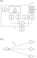
- FIG 1 shows a schematic block diagram according to an embodiment of a machine 10 with an embodiment of a monitoring device 12.
- the monitoring device 12 has at least one detection device 14 for detecting a measurement signal 16 and an electronic computing device 18.
- the FIG 1 the monitoring device 12 for determining a cause of error 20 of the machine 10.
- the machine 10 has a first component 22, for example in the form of a pump, and a second component 24, for example in the form of a valve.
- a digital Twin model 26 of the machine 10 by means of the electronic computing device 18.
- a dependency model 28 of the respective components 22, 24 of the machine 10 is provided by means of the electronic computing device 18, wherein the components 22, 24 are susceptible to errors.
- a measurement signal 16 of the machine 10 is recorded by means of the recording device 14.
- the digital twin model 26 is simulated by means of the electronic computing device 18, and a virtual measurement signal 30 of the digital twin model 26 is output by means of the electronic computing device 18.
- the measurement signal 16 is compared with the virtual measurement signal 30 by means of the electronic computing device 18, in particular in a comparison module 32. If the measurement signal 16 deviates from the virtual measurement signal 30, the cause of the error 20 is determined depending on the dependency model 28 by means of the electronic computing device 18.
- the machine 10 and the digital twin model 26 are operated at the same time and in parallel to one another.
- at least one error model 34 can be specified for a respective component 22, 24.
- a plurality of error models 34 can also be specified for a respective component 22, 24.
- the at least one error model 34 can be simulated and a further virtual measurement signal 36 dependent thereon can be compared with the measurement signal 16 and, if there is a match, the errors can be determined on the basis of the error model 34.
- the dependency model 28 can take into account components 22, 24 which have an effect on the measurement signal 16.
- the digital twin model 26 and the machine 10 are started at the same time.
- FIG 2 shows in particular a schematic view of a dependency model 28.
- the measurement signal 16 is dependent on the component 22 and the component 24, for example.
- the cause of the error 20 can then be determined depending on the measurement signal 16.
- the dependency model 28 is provided as a dependency graph.
- the invention proposes that the dependency model 28 is initially specified.
- the dependency model 28 describes for each input signal of the controller which actuator it is dependent on, with the measurement signal 16 in particular being recorded as the input signal.
- the digital twin model 26 of the machine 10 is constructed. Like the real machine 10, the digital twin model 26 has a controller. The controller must process the same control project in the same way as the controller of the real machine 10. The controller can, however, be available as hardware or software.
- the physics of the real machine 10, in particular mechanical movements, pressures, forces or the like, are mapped as realistically as necessary via the digital twin model 26. For each component 22, 24 identified in the dependency model 28, the corresponding error models 34 are implemented in the digital twin model 26.
- the component 22, 24 can be simulated in a "good state", i.e. error-free state, or in an error state.
- the component 22, 24 can have several error states. These must be instantiated individually or in combination and stored in particular in the error model 34.
- the digital twin model 26 must be modulated in such a way that it runs in real time and synchronously with the real machine 10.
- a functionality is implemented so that the real machine 10 and the digital twin model 26 can be started synchronously.
- a functionality is implemented that converts all signals of the real system, in particular of the machine 10, available in the control system into continuously save data at a predefined time interval. The data is saved over a set period of time. The saved data is then automatically overwritten by new values.
- a functionality is specified that continuously compares all signals of the machine 10 and the digital twin model 26.
- the digital twin model 26 is stopped; in particular, a change in the operating state of the real machine 10 is also possible.
- the dependency model 28 is used to analyze what the deviating measurement signal 16 depends on. It can have one or more dependencies. These dependencies are systematically tested using the digital twin model 26. In particular, a dependency can then be selected.
- the digital twin model 26 corresponds to the last time step in which there was no deviation.
- the error model 34 is now instantiated for the selected component 22, 24.
- the digital twin model 26 is now simulated with this error model 34, and it is checked whether the detected deviation between the machine 10 and the digital twin model 26 can be proven by means of the simulation.
- FIG 3 shows a schematic flow chart according to an embodiment of the method.
- a first step S1 the digital twin model 26 and the machine 10 are provided in parallel.
- a second step S2 the digital twin model 26 and the machine 10 start.
- a third step S3 the simulation is again carried out, while in a fourth step S4 the machine 10 is in operation.
- the measurement signal 16 is again recorded and the virtual measurement signal 30 is generated and compared.
- a sixth step S6 it is checked whether these are the same. If they are the same, the process continues with a seventh step S7, whereupon a new monitoring cycle begins with the first step S1. If the signals 16, 30 differ, an eighth step S8 is carried out.
- step S8 it is checked which dependencies are present in the dependency model 28 that could influence the corresponding measurement signal 16.
- step S9 the corresponding paths in the dependency model 28 are then checked.
- step S10 the simulation is then divided into the different components 22, 24.
- the first component 22 is checked in an eleventh step S11, and in particular the error model 34 is used.
- step S12 the virtual control is then executed without deviation, in particular with the last stored digital twin model 26.
- a thirteenth step S13 it is then checked whether the further virtual measurement signal 36 matches the measurement signal 16. If this is the case, the process goes to a fourteenth step S14, where the cause of the error 20 is then found.
- a fifteenth step S15 it is determined in a fifteenth step S15 that it is the wrong path and thus the checked component 22, 24 is not the cause of the error 20.
- a sixteenth step S16 can be carried out in parallel, as shown here, which in turn provides the second component 24 with the error model 16.
- the further virtual measurement signal 36 is virtually checked with the corresponding controls and the last model before the deviation.
- the comparison is then made with the measurement signal 16 and the further virtual measurement signal 36. If there is a match, in a nineteenth step S19 can be used to determine that this is the cause of the error 20. If these measurement signals do not match, it can be checked in a twentieth step S20 that this is not the cause of the error 20.
- the FIGS 1 to 3 The method described or the monitoring device 12 thus also makes it possible to find out the causes of errors 20 in the control system. These are based on the automated evaluation of the machine 10 via the digital twin model 26.
- the digital twin model 26 can be calculated very quickly, so that many possible causes of the error 20 can be analyzed in a short time.
- the simulation shows the temporal progression. The simulation can thus be used to qualitatively and quantitatively analyze and prove the origin of the error.
- participants that do not offer their own diagnostic option, such as a valve can also be identified as the cause.
- the respective component causing the error can then be controlled by means of the monitoring device 12 and, for example, shut down, switched off, specially monitored and/or controlled in a fault-specific manner.
- a machine system is shown in particular, which is designed in particular at least with the monitoring device 12 and the machine 10.
Landscapes
- Physics & Mathematics (AREA)
- General Physics & Mathematics (AREA)
- Engineering & Computer Science (AREA)
- Automation & Control Theory (AREA)
- Testing And Monitoring For Control Systems (AREA)
Priority Applications (1)
| Application Number | Priority Date | Filing Date | Title |
|---|---|---|---|
| EP23194481.0A EP4517461A1 (fr) | 2023-08-31 | 2023-08-31 | Procédé de détermination d'une cause de défaillance dans une machine au moyen d'un dispositif de surveillance |
Applications Claiming Priority (1)
| Application Number | Priority Date | Filing Date | Title |
|---|---|---|---|
| EP23194481.0A EP4517461A1 (fr) | 2023-08-31 | 2023-08-31 | Procédé de détermination d'une cause de défaillance dans une machine au moyen d'un dispositif de surveillance |
Publications (1)
| Publication Number | Publication Date |
|---|---|
| EP4517461A1 true EP4517461A1 (fr) | 2025-03-05 |
Family
ID=87889257
Family Applications (1)
| Application Number | Title | Priority Date | Filing Date |
|---|---|---|---|
| EP23194481.0A Withdrawn EP4517461A1 (fr) | 2023-08-31 | 2023-08-31 | Procédé de détermination d'une cause de défaillance dans une machine au moyen d'un dispositif de surveillance |
Country Status (1)
| Country | Link |
|---|---|
| EP (1) | EP4517461A1 (fr) |
Citations (2)
| Publication number | Priority date | Publication date | Assignee | Title |
|---|---|---|---|---|
| US20230168961A1 (en) * | 2021-11-30 | 2023-06-01 | Caterpillar Inc. | Systems and methods for identifying machine anomaly root cause |
| EP4220460A1 (fr) * | 2022-01-31 | 2023-08-02 | Siemens Aktiengesellschaft | Détermination d'une cause d'une défaillance lors du fonctionnement d'un système cyber-physique |
-
2023
- 2023-08-31 EP EP23194481.0A patent/EP4517461A1/fr not_active Withdrawn
Patent Citations (2)
| Publication number | Priority date | Publication date | Assignee | Title |
|---|---|---|---|---|
| US20230168961A1 (en) * | 2021-11-30 | 2023-06-01 | Caterpillar Inc. | Systems and methods for identifying machine anomaly root cause |
| EP4220460A1 (fr) * | 2022-01-31 | 2023-08-02 | Siemens Aktiengesellschaft | Détermination d'une cause d'une défaillance lors du fonctionnement d'un système cyber-physique |
Non-Patent Citations (1)
| Title |
|---|
| AIVALIOTIS P. ET AL: "The use of Digital Twin for predictive maintenance in manufacturing", INTERNATIONAL JOURNAL OF COMPUTER INTEGRATED MANUFACTURING., vol. 32, no. 11, 2 November 2019 (2019-11-02), GB, pages 1067 - 1080, XP055888111, ISSN: 0951-192X, Retrieved from the Internet <URL:https://www.tandfonline.com/doi/pdf/10.1080/0951192X.2019.1686173> DOI: 10.1080/0951192X.2019.1686173 * |
Similar Documents
| Publication | Publication Date | Title |
|---|---|---|
| EP1192543B1 (fr) | Procede et systeme pour determiner l'arborescence de defaillances d'un systeme technique, produit de programme informatique et support d'information lisible par ordinateur associe | |
| DE2735397C2 (de) | Überwachungseinrichtung für eine programmgesteuerte Maschine | |
| EP2685382B1 (fr) | Procédé et dispositif de création et de test d'un programme d'appareil de commande | |
| EP1552128B1 (fr) | Procede, appareil de commande, et programme informatique pour detecter des detecteurs de pression defectueux dans un moteur a combustion interne | |
| DE3702408C2 (fr) | ||
| DE102018203280A1 (de) | Zustandsdiagnosevorrichtung | |
| EP2273369A1 (fr) | Procédé de représentation d'une information relative à la sécurité sur un dispositif d'affichage et dispositif d'exécution du procédé | |
| WO1998040796A1 (fr) | Procede d'analyse assistee par ordinateur de defaillances de capteurs et/ou d'actionneurs dans un systeme technique | |
| DE102019131865A1 (de) | Verfahren und vorrichtung zur eigendiagnose der ram-fehlererkennungslogik eines antriebsstrangcontrollers | |
| EP3493000B1 (fr) | Procédé de détection de manière protégée contre les erreurs d'une valeur mesurée et système d'automatisation | |
| EP1703350B1 (fr) | Diagnostic d'un système d'automatisation | |
| EP1860565B1 (fr) | Procédé destiné à la vérification du fonctionnement d'un appareil de commande pour un véhicule automobile | |
| EP1359485B1 (fr) | Système de commande et surveillance | |
| DE19742448C1 (de) | Diagnosemodul zum Erstellen einer Diagnose für elektrisch ansteuerbare Systeme und Diagnoseeinrichtung zum Erstellen einer Gesamtsystemdiagnose | |
| EP4517461A1 (fr) | Procédé de détermination d'une cause de défaillance dans une machine au moyen d'un dispositif de surveillance | |
| DE102022134209B3 (de) | Verfahren, Diagnoseeinrichtung und System zum Überwachen eines Betriebs einer Brennkraftmaschine | |
| EP3260826B1 (fr) | Procédé de fonctionnement d'un débitmètre et débitmètre | |
| DE102007015369A1 (de) | Verfahren zur Überwachung des logischen Programmablaufs von kritischen Funktionen in Programmen eines Feldgeräts der Prozess- und Automatisierungstechnik | |
| DE102013010783A1 (de) | Verfahren und Steuergerät zum Testen einer Automatisierungslösung basierend auf einer PLC-Steuerung | |
| EP4092535B1 (fr) | Procédé d'essai d'appareils de commande | |
| DE102010031323A1 (de) | Verfahren und Vorrichtung zum Betreiben einer Brennkraftmaschine | |
| WO2006108849A1 (fr) | Procede et unite d'ordinateur destines a la detection et a la mise en protocole d'erreurs dans une memoire | |
| EP1507181B1 (fr) | Procédé et dispositif de traitement de données à niveaux multiples, en particulier pour diagnostiques, dans une installation technique | |
| DE102004037687B4 (de) | Zusicherungen in physikalischen Modellbeschreibungen für Funktionen und ihre Verwendung bei der Erzeugung von Code für Mikroprozessor basierte Steuergeräte | |
| EP4502738A1 (fr) | Circuit pour la commande d'une machine, système de machine, ainsi que procédé de production d'un signal de commande |
Legal Events
| Date | Code | Title | Description |
|---|---|---|---|
| PUAI | Public reference made under article 153(3) epc to a published international application that has entered the european phase |
Free format text: ORIGINAL CODE: 0009012 |
|
| STAA | Information on the status of an ep patent application or granted ep patent |
Free format text: STATUS: THE APPLICATION HAS BEEN PUBLISHED |
|
| AK | Designated contracting states |
Kind code of ref document: A1 Designated state(s): AL AT BE BG CH CY CZ DE DK EE ES FI FR GB GR HR HU IE IS IT LI LT LU LV MC ME MK MT NL NO PL PT RO RS SE SI SK SM TR |
|
| STAA | Information on the status of an ep patent application or granted ep patent |
Free format text: STATUS: THE APPLICATION IS DEEMED TO BE WITHDRAWN |
|
| 18D | Application deemed to be withdrawn |
Effective date: 20250906 |