EP4517465A2 - Moving devices used in liquid and pool cleaning robots - Google Patents
Moving devices used in liquid and pool cleaning robots Download PDFInfo
- Publication number
- EP4517465A2 EP4517465A2 EP25152420.3A EP25152420A EP4517465A2 EP 4517465 A2 EP4517465 A2 EP 4517465A2 EP 25152420 A EP25152420 A EP 25152420A EP 4517465 A2 EP4517465 A2 EP 4517465A2
- Authority
- EP
- European Patent Office
- Prior art keywords
- moving device
- cleaning robot
- dust box
- pool cleaning
- buoyancy
- Prior art date
- Legal status (The legal status is an assumption and is not a legal conclusion. Google has not performed a legal analysis and makes no representation as to the accuracy of the status listed.)
- Pending
Links
Images






Classifications
-
- A—HUMAN NECESSITIES
- A46—BRUSHWARE
- A46B—BRUSHES
- A46B13/00—Brushes with driven brush bodies or carriers
- A46B13/001—Cylindrical or annular brush bodies
- A46B13/005—Cylindrical or annular brush bodies made up of a series of longitudinal strips or segments
-
- A—HUMAN NECESSITIES
- A46—BRUSHWARE
- A46B—BRUSHES
- A46B13/00—Brushes with driven brush bodies or carriers
- A46B13/02—Brushes with driven brush bodies or carriers power-driven carriers
-
- A—HUMAN NECESSITIES
- A46—BRUSHWARE
- A46B—BRUSHES
- A46B15/00—Other brushes; Brushes with additional arrangements
- A46B15/0055—Brushes combined with other articles normally separate from the brushing process, e.g. combs, razors, mirrors
- A46B15/0081—Brushes with a scraper, e.g. tongue scraper
-
- B—PERFORMING OPERATIONS; TRANSPORTING
- B63—SHIPS OR OTHER WATERBORNE VESSELS; RELATED EQUIPMENT
- B63G—OFFENSIVE OR DEFENSIVE ARRANGEMENTS ON VESSELS; MINE-LAYING; MINE-SWEEPING; SUBMARINES; AIRCRAFT CARRIERS
- B63G8/00—Underwater vessels, e.g. submarines; Equipment specially adapted therefor
- B63G8/001—Underwater vessels adapted for special purposes, e.g. unmanned underwater vessels; Equipment specially adapted therefor, e.g. docking stations
-
- B—PERFORMING OPERATIONS; TRANSPORTING
- B63—SHIPS OR OTHER WATERBORNE VESSELS; RELATED EQUIPMENT
- B63G—OFFENSIVE OR DEFENSIVE ARRANGEMENTS ON VESSELS; MINE-LAYING; MINE-SWEEPING; SUBMARINES; AIRCRAFT CARRIERS
- B63G8/00—Underwater vessels, e.g. submarines; Equipment specially adapted therefor
- B63G8/08—Propulsion
-
- B—PERFORMING OPERATIONS; TRANSPORTING
- B63—SHIPS OR OTHER WATERBORNE VESSELS; RELATED EQUIPMENT
- B63G—OFFENSIVE OR DEFENSIVE ARRANGEMENTS ON VESSELS; MINE-LAYING; MINE-SWEEPING; SUBMARINES; AIRCRAFT CARRIERS
- B63G8/00—Underwater vessels, e.g. submarines; Equipment specially adapted therefor
- B63G8/14—Control of attitude or depth
-
- B—PERFORMING OPERATIONS; TRANSPORTING
- B63—SHIPS OR OTHER WATERBORNE VESSELS; RELATED EQUIPMENT
- B63G—OFFENSIVE OR DEFENSIVE ARRANGEMENTS ON VESSELS; MINE-LAYING; MINE-SWEEPING; SUBMARINES; AIRCRAFT CARRIERS
- B63G8/00—Underwater vessels, e.g. submarines; Equipment specially adapted therefor
- B63G8/14—Control of attitude or depth
- B63G8/22—Adjustment of buoyancy by water ballasting; Emptying equipment for ballast tanks
-
- C—CHEMISTRY; METALLURGY
- C02—TREATMENT OF WATER, WASTE WATER, SEWAGE, OR SLUDGE
- C02F—TREATMENT OF WATER, WASTE WATER, SEWAGE, OR SLUDGE
- C02F1/00—Treatment of water, waste water, or sewage
- C02F1/001—Processes for the treatment of water whereby the filtration technique is of importance
-
- E—FIXED CONSTRUCTIONS
- E04—BUILDING
- E04H—BUILDINGS OR LIKE STRUCTURES FOR PARTICULAR PURPOSES; SWIMMING OR SPLASH BATHS OR POOLS; MASTS; FENCING; TENTS OR CANOPIES, IN GENERAL
- E04H4/00—Swimming or splash baths or pools
- E04H4/12—Devices or arrangements for circulating water, i.e. devices for removal of polluted water, cleaning baths or for water treatment
- E04H4/1209—Treatment of water for swimming pools
- E04H4/1263—Floating skimmers
-
- E—FIXED CONSTRUCTIONS
- E04—BUILDING
- E04H—BUILDINGS OR LIKE STRUCTURES FOR PARTICULAR PURPOSES; SWIMMING OR SPLASH BATHS OR POOLS; MASTS; FENCING; TENTS OR CANOPIES, IN GENERAL
- E04H4/00—Swimming or splash baths or pools
- E04H4/14—Parts, details or accessories not otherwise provided for
- E04H4/16—Parts, details or accessories not otherwise provided for specially adapted for cleaning
- E04H4/1654—Self-propelled cleaners
-
- G—PHYSICS
- G05—CONTROLLING; REGULATING
- G05D—SYSTEMS FOR CONTROLLING OR REGULATING NON-ELECTRIC VARIABLES
- G05D1/00—Control of position, course, altitude or attitude of land, water, air or space vehicles, e.g. using automatic pilots
- G05D1/40—Control within particular dimensions
- G05D1/48—Control of altitude or depth
-
- G—PHYSICS
- G05—CONTROLLING; REGULATING
- G05D—SYSTEMS FOR CONTROLLING OR REGULATING NON-ELECTRIC VARIABLES
- G05D1/00—Control of position, course, altitude or attitude of land, water, air or space vehicles, e.g. using automatic pilots
- G05D1/60—Intended control result
- G05D1/648—Performing a task within a working area or space, e.g. cleaning
-
- A—HUMAN NECESSITIES
- A46—BRUSHWARE
- A46B—BRUSHES
- A46B2200/00—Brushes characterized by their functions, uses or applications
- A46B2200/30—Brushes for cleaning or polishing
- A46B2200/3073—Brush for cleaning specific unusual places not otherwise covered, e.g. gutters, golf clubs, tops of tin cans, corners
-
- B—PERFORMING OPERATIONS; TRANSPORTING
- B63—SHIPS OR OTHER WATERBORNE VESSELS; RELATED EQUIPMENT
- B63G—OFFENSIVE OR DEFENSIVE ARRANGEMENTS ON VESSELS; MINE-LAYING; MINE-SWEEPING; SUBMARINES; AIRCRAFT CARRIERS
- B63G8/00—Underwater vessels, e.g. submarines; Equipment specially adapted therefor
- B63G8/001—Underwater vessels adapted for special purposes, e.g. unmanned underwater vessels; Equipment specially adapted therefor, e.g. docking stations
- B63G2008/002—Underwater vessels adapted for special purposes, e.g. unmanned underwater vessels; Equipment specially adapted therefor, e.g. docking stations unmanned
-
- C—CHEMISTRY; METALLURGY
- C02—TREATMENT OF WATER, WASTE WATER, SEWAGE, OR SLUDGE
- C02F—TREATMENT OF WATER, WASTE WATER, SEWAGE, OR SLUDGE
- C02F2103/00—Nature of the water, waste water, sewage or sludge to be treated
- C02F2103/42—Nature of the water, waste water, sewage or sludge to be treated from bathing facilities, e.g. swimming pools
-
- C—CHEMISTRY; METALLURGY
- C02—TREATMENT OF WATER, WASTE WATER, SEWAGE, OR SLUDGE
- C02F—TREATMENT OF WATER, WASTE WATER, SEWAGE, OR SLUDGE
- C02F2201/00—Apparatus for treatment of water, waste water or sewage
- C02F2201/008—Mobile apparatus and plants, e.g. mounted on a vehicle
-
- G—PHYSICS
- G05—CONTROLLING; REGULATING
- G05D—SYSTEMS FOR CONTROLLING OR REGULATING NON-ELECTRIC VARIABLES
- G05D2105/00—Specific applications of the controlled vehicles
- G05D2105/10—Specific applications of the controlled vehicles for cleaning, vacuuming or polishing
-
- G—PHYSICS
- G05—CONTROLLING; REGULATING
- G05D—SYSTEMS FOR CONTROLLING OR REGULATING NON-ELECTRIC VARIABLES
- G05D2107/00—Specific environments of the controlled vehicles
- G05D2107/25—Aquatic environments
- G05D2107/29—Swimming pools
-
- G—PHYSICS
- G05—CONTROLLING; REGULATING
- G05D—SYSTEMS FOR CONTROLLING OR REGULATING NON-ELECTRIC VARIABLES
- G05D2109/00—Types of controlled vehicles
- G05D2109/10—Land vehicles
- G05D2109/15—Climbing vehicles
-
- G—PHYSICS
- G05—CONTROLLING; REGULATING
- G05D—SYSTEMS FOR CONTROLLING OR REGULATING NON-ELECTRIC VARIABLES
- G05D2109/00—Types of controlled vehicles
- G05D2109/30—Water vehicles
- G05D2109/34—Water vehicles operating on the water surface
-
- G—PHYSICS
- G05—CONTROLLING; REGULATING
- G05D—SYSTEMS FOR CONTROLLING OR REGULATING NON-ELECTRIC VARIABLES
- G05D2109/00—Types of controlled vehicles
- G05D2109/50—Vehicles specially adapted for two or more of space, air, land or water environments, e.g. amphibious vehicles
Definitions
- the present disclosure relates to the field of water cleaning, and in particular, to a moving device used in liquid and a pool cleaning robot.
- Pool cleaning robots on the market can be divided into three types.
- the first type of cleaning robot can only clean the bottom of the water.
- the second type of cleaning robot can clean both the bottom and the vertical wall surface but shall be below the surface of the water.
- the third type of cleaning robot needs to be floating on the surface of the water, and can only clean the surface of the water.
- Each of the three types of pool cleaning robots has its own characteristics, but they all lack effective position adjustment in the liquid environment and cannot adjust the depth according to the actual need for all-round cleaning of the bottom, wall surface and water surface of the pool, which limits their application scope and work efficiency.
- the moving device includes: a mode switching member configured to achieve a position switching of the moving device above a liquid surface and below the liquid surface. When the moving device is below the liquid surface, the moving device is fully submerged below the liquid surface, and when the moving device is above the liquid surface, at least a portion of the moving device is above the liquid surface.
- the pool cleaning robot includes a dust box including a dust box opening configured to clean liquid that enters the dust box; a moving device as described in the above embodiment; and a control member configured to control the pool cleaning robot to perform a water surface cleaning of a pool or an underwater cleaning of the pool.
- the liquid cleaning control method is applied to a pool cleaning robot as described in the above embodiment, and performed by a control member.
- the liquid cleaning control method includes obtaining a target task for cleaning a target pool, wherein the target task includes a water surface cleaning and/or an underwater cleaning; determining an adjustment parameter of the moving device based on the target task and a current position of the pool cleaning robot; and controlling, based on the adjustment parameter, the moving device to drive the pool cleaning robot to move to a target position to accomplish the target task.
- the buoyancy cavity 1111 may be configured to accommodate liquid and/or gas.
- the buoyancy cavity 1111 may also include, but is not limited to, an inflatable buoyancy cavity, a liquid container type buoyancy cavity, a separated buoyancy cavity, etc.
- a volume of the buoyancy cavity 1111 may be preset.
- the buoyancy cavity 1111 may be made of a flexible material and/or a rigid material.
- the aforementioned flexible material may include, but is not limited to, polyvinyl alcohol resin, polyethylene terephthalate, rubber, etc.
- the rigid material may include but is not limited to, glass, ceramics, phenolic plastics, polyurethane plastics, epoxy plastics, unsaturated polyester plastics, etc.
- the buoyancy force adjustment assembly 111 may also include an air inlet 1113.
- the aforementioned air inlet 1113 is configured to supply gas into the buoyancy cavity 1111.
- the aforementioned air inlet 1113 may also be configured for the gas to leave the buoyancy cavity 1111, or for the liquid to enter or leave the buoyancy cavity 1111.
- the buoyancy force adjustment assembly 111 may also include other inlets and outlets for the exit of the gas or the entry or exit of the liquid.
- the air inlet 1113 may be provided directly on the buoyancy cavity 1111 or may also be independent of the buoyancy cavity 1111.
- the moving device 100 may include a first sensor (not shown).
- the first sensor may be configured to determine the position of the moving device 100 in real time.
- the aforementioned position may include a vertical position (or depth) of the moving device 100 in the liquid.
- the first sensor may be provided at a central position of the moving device, and the aforementioned position may be a depth of the central position of the moving device 100 in the liquid.
- the first sensor may include, but is not limited to, a pressure sensor, an ultrasonic sensor, an optical sensor, etc.
- the moving device 100 may also include a second sensor (not shown).
- the second sensor may be configured to detect in real time whether the air inlet of the buoyancy cavity 1111 is positioned in air.
- the second sensor may include an ultrasonic sensor.
- the second sensor may be provided at the position of the air inlet of the buoyancy cavity 1111.
- the second sensor may also be provided at other positions of the moving device 100 and obtain a detection result of whether the air inlet is located in the air by a position transition.
- the processor may obtain a detection result of whether the air inlet of the buoyancy cavity 1111 is located in the air, and when the detection result characterizes that the aforementioned air inlet is located in the air, the buoyancy force adjustment member is controlled to increase the volume of the gas in the buoyancy cavity 1111 to achieve the switching of the moving device 100 from below the liquid surface to above the liquid surface.
- the processor controlling the buoyancy force adjustment member to increase the volume of gas in the buoyancy cavity 1111 to enable the moving device 100 to be switched from below the liquid surface to above the liquid surface please refer to the above section of the present disclosure.
- the buoyancy force adjustment component 111 may be provided to adjust the magnitude of the buoyancy force to which the moving device 100 is subjected in the vertical direction, thereby achieving flexible switching of the moving device 100 above the liquid surface and below the liquid surface, and improving the efficiency and reliability of the moving device 100 in the liquid environment.
- the moving device 100 can automatically determine the environment in which the air inlet 1113 is located, which improves the efficiency of the use of the moving device 100.
- the mode switching member 110 may also include a power adjustment assembly.
- the power adjustment assembly may be configured to adjust the first drive force to which the moving device 100 is subjected in the vertical direction.
- the power adjustment assembly may be a variety of structures that can provide the first drive force.
- the power adjustment assembly may include a propeller, and the aforementioned propeller may be provided vertically on the moving device 100, and by rotating the aforementioned propeller, the moving device 100 may be made to obtain the first drive force in the vertical direction.
- the first drive force in the vertical direction may be upward or downward, and under the action of the first drive force, the moving device 100 may move upward or downward in the vertical direction, or be suspended in a certain position in the liquid.
- the power adjustment assembly may include the first propeller 112.
- the first propeller 112 may be configured to propel the liquid in a first preset direction.
- the first preset direction may be a direction in which the first propeller 112 discharges the liquid.
- the moving device 100 may be subjected to a reaction force opposite to the first preset direction, and the aforementioned reaction force may include the first drive force.
- the first preset direction includes at least an inclination in the vertical direction to ensure that the obtained reaction force as mentioned before has a division force in the vertical direction (i.e., the first drive force). Accordingly, an angle between the first preset direction and the vertical direction may be [0°, 90°).
- the magnitude of the first drive force may also be negatively correlated with the angle between the first preset direction and the vertical direction.
- the greater the angle between the first preset direction and the vertical direction is, the smaller the first drive force of the moving device 100 in the vertical direction is.
- the aforementioned reaction force on the moving device 100 may be completely converted to the first drive force in the vertical direction.
- the moving device 100 may include one or more first propellers 112.
- the first propeller 112 may be provided at various positions in the moving device 100. As shown in FIG. 5 and FIG. 7A , the first propeller 112 may be vertically provided in the central position of the moving device 100 to ensure the balance during the movement of the moving device 100.
- the first propeller 112 may include an impeller 1121 and a motor assembly 1122.
- the impeller 1121 may drive the liquid in the first preset direction by rotation, and when the liquid moves in the first preset direction, the moving device 100 is subjected to the first drive force in the vertical direction.
- the motor assembly 1122 may power the aforementioned impeller 1121.
- the first propeller 112 in the moving device 100 may include two openings 1123.
- the second propeller 120 when the second propeller 120 is provided on the side of the moving device 100, its setting position should be at least partially below a floating position of the moving device 100 on the liquid surface to ensure that when the moving device 100 is floating on the liquid surface, the impeller rotation in the second propeller 120 can propel the liquid in the second preset direction, to provide the second drive force in the horizontal direction for the moving device 100.
- the setting position of the second propeller 120 when the second propeller 120 is provided on the side of the moving device 100, the setting position of the second propeller 120 may be all below the floating position of the moving device 100 on the liquid surface.
- at least one second propeller 120 may be provided on each of a left side and a right side of the moving device 100. As shown in FIG.
- the moving device 100 may also include a track 130.
- the operation of the track 130 may drive the movement of the moving device 100.
- the track 130 may also drive the moving device 100 in the vertical direction. As shown in FIGs. 4A and 6C , the operation of the track 130 also drives the moving device 100 on the side wall 320 of the target region 300 when the moving device 100 is pressed against the side wall 320. For more information about how the moving device 100 is achieved by pressing against the side wall 320 of the target region 300, please refer to the following part of the present disclosure.
- the track 130 may also enable a transition of a moving region of the moving device 100 from the bottom wall 310 to the side wall 320. As shown in FIG. 6B , when the track 130 moves to a point where the bottom wall 310 meets the side wall 320, a portion of the track 130 moves on the side wall 320 and a portion moves on the bottom wall 310. A portion of the track 130 at the side wall 320 may drive the moving device 100 upward until the moving region of the moving device 100 transitions from the bottom wall 310 to the side wall 320.
- the moving device 100 may move on the side wall 320 driven by the track 130, the moving device 100 may also move on the side wall 320 under the action of the second drive force provided by the second propeller 120 after steering, and the moving device 100 may also move on the side wall 320 based on the action of a third drive force provided by a main water pump 140.
- a main water pump 140 For more information about the main water pump 140 and the third drive force, please refer to the following part of the present disclosure.
- Some embodiments of the present disclosure can facilitate the movement of the moving device 100 in various positions in the liquid by providing the track 130 and enable the transition of the moving region of the moving device 100 from the bottom wall 310 to the side wall 320.
- the moving device 100 may also include the main water pump 140.
- the main water pump 140 may be configured to drive the moving device 100 to absorb the liquid from a water inlet and discharge it from a water outlet.
- the water inlet may include one or more inlets for the liquid to enter the moving device 100.
- the main water pump inlet 141 in the moving device 100 may serve as an inlet (i.e., a water inlet) for the liquid to enter the inside of the moving device 100.
- the water outlet may include one or more outlets in the moving device 100 where the liquid leaves the moving device 100 and enters the target region 300.
- the main water pump outlet 142 in the moving device 100 may serve as an outlet (i.e., a water outlet) for the liquid in the moving device 100 to leave the moving device 100 and enter the target region 300.
- the water outlet (e.g., the main pump outlet 142) may be oriented at least within the target region 300 and parallel to a horizontal direction or with a downward slope in a vertical direction, thereby guaranteeing that when the main water pump 140 is in operation and the liquid is discharged from the main pump outlet 142, the moving device 100 may receive the third drive force to drive the moving device 100 to press against the side wall 320.
- the third drive force may include a reaction force obtained by the moving device 100 when the main water pump 140 discharges the liquid from the main water pump outlet 142.
- the main pump outlet 142 When the main pump outlet 142 is oriented inside the target region 300 and parallel to the horizontal direction, the third drive force obtained by the moving device 100 is oriented vertically towards the side wall 320, so that the moving device 100 may be made to press against the side wall 320. In some embodiments, when the moving device 100 needs to move on the side wall 320, the main water pump outlet 142 may be directed within the target region 300.
- the third drive force obtained by the moving device 100 may exist a component force in the horizontal direction towards the side wall 320, which may cause the moving device 100 to press against the side wall 320; on the other hand, the aforementioned third drive force may also exist a component force in the vertical direction with an upward division force, thereby also allowing the moving device 100 to move upwardly along the side wall 320.
- the third drive force obtained by the main water pump 140 discharging through the aforementioned main water pump outlet 142 may also exist a component force in the horizontal direction, thereby also allowing the moving device 100 to move on the bottom wall 310.
- the pool cleaning robot 400 may be configured to clean the pool.
- the pool cleaning robot 400 may include a moving device 100, a dust box 410, and a control member.
- the dust box 410 may be configured for a water surface cleaning and an in-water cleaning of the pool.
- the control member in the aforementioned pool cleaning robot 400 controls the moving device 100 to switch positions in the water surface of the pool and underwater to achieve the water surface cleaning or underwater cleaning.
- the dust box 410 may include one or more dust box openings.
- the dust box opening may be configured for an entrance of trash or other impurities from the pool into the pool cleaning robot 400.
- Some embodiments of the present disclosure ensure a comprehensive pool cleaning by providing the pool cleaning robot 400 with the moving device 100 to clean the pool in multiple positions such as the bottom, the water, and the surface of the pool in an all-round manner.
- the pool cleaning robot 400 may also include a trash guiding member 420.
- the trash guiding member 420 may drive the trash in the liquid surface of the pool into the water surface dust box opening 411. As shown in FIG. 8 and FIG. 9 , the trash guiding member 420 may be located on an outside of the water surface dust box opening 411 and be hollow inside.
- the trash guiding member 420 may be with a size of a first end 421 away from the water surface dust box opening 411 that is larger than a size of the water surface dust box opening 411, and a size of a second end 422 connected to the water surface dust box opening 411 that is not smaller than the size of the water surface dust box opening 411.
- the trash guiding member 420 may include, but is not limited to, structures such as a truncated cone, a trapezoid, etc., whose interior are hollow.
- the pool cleaning robot 400 may also include a main roller brush 430.
- the main roller brush 430 may be configured to clean the bottom wall 310 and the side wall 320 of the pool.
- the pool cleaning robot 400 may include one or more main roller brushes 430.
- the main roller brush 430 may be provided on the bottom and/or side of the pool cleaning robot 400.
- the pool cleaning robot 400 may be provided with one main roller brush 430 at each of a front and rear end of the bottom of the pool cleaning robot 400.
- the main roller brush 430 may clean the bottom of the pool (e.g., sweep for impurities or algae); when the pool cleaning robot 400 moves over the walls of the pool, the main roller brush 430 may also clean the walls of the pool.
- the target pool may be a pool that needs to be cleaned.
- the target task may be a cleaning task that needs to be performed on the target pool.
- the target task may include a water surface cleaning and/or an underwater cleaning.
- the water surface cleaning may refer to cleaning the water surface of the target pool
- the underwater cleaning may refer to cleaning the underwater (e.g., the water body, the walls of the pool, etc.) of the target pool.
- the target task may also include a specific cleaning site.
- the underwater cleaning may also include, but is not limited to, a water body cleaning, a pool bottom cleaning, an individual pool wall cleaning, etc.
- the water quality data includes, but is not limited to, a picture of the water surface of the target pool, a picture of the water, a picture of the individual pool walls, etc.
- the control member may input the water quality data into a task determination model, and an output of the task determination model may include the target task.
- the task determination model may analyze the water quality data of the target pool to determine the cleanliness (e.g., clarity, algae distribution, impurities, etc.) of each region (e.g., water surface, water, individual pool walls, etc.) and thus determine the corresponding target task.
- the task determination model may include a convolutional neural network model, a graph neural network, or any other machine learning model that can implement this function.
- the task determination model may be obtained by training based on multiple sets of training samples with labels.
- the training samples may include sample water quality data from a sample pool, and the labels may include a sample task.
- the sample task may be obtained by manually labeling the sample water quality data.
- an adjustment parameter of the moving device may be determined based on the target task and a current position of the pool cleaning robot.
- the adjustment parameter may include route information for moving from the current position to a position of the target pool where the target task needs to be performed and route information required to complete the target task.
- Some embodiments of the present disclosure enable control of the pool cleaning robot 400 to clean all parts of the pool through the aforementioned liquid cleaning control method to improve pool cleaning efficiency while ensuring the comprehensive pool cleaning.
- Some embodiments of the present disclosure also provide a non-transitory computer-readable storage medium.
- the storage medium may include a set of instructions. When the set of instructions are executed by a processor, a liquid cleaning control method as described above is implemented.
- the present disclosure uses specific words to describe the embodiments of the present disclosure.
- “one embodiment,” “an embodiment,” and/or “some embodiments” mean that a certain feature, structure, or characteristic is connected with at least one embodiment of the present disclosure. Therefore, it should be emphasized and noted that two or more references of “an embodiment” or “one embodiment” or “an alternative embodiment” in various places in the present disclosure do not necessarily refer to the same embodiment. Further, certain features, structures, or features of one or more embodiments of the present disclosure may be combined.
- the pool cleaning robot as above further comprising: a trash guiding member configured to drive the trash in a water surface of the pool into the water surface dust box opening, the trash guiding member being located on an outside of the water surface dust box opening and being hollow inside, a size of a first end of the trash guiding member away from the water surface dust box opening being larger than a size of the water surface dust box opening, and a size of a second end of the trash guiding member connected to the water surface dust box opening being not smaller than the size of the water surface dust box opening.
Landscapes
- Engineering & Computer Science (AREA)
- Architecture (AREA)
- Aviation & Aerospace Engineering (AREA)
- Mechanical Engineering (AREA)
- Civil Engineering (AREA)
- Structural Engineering (AREA)
- Water Supply & Treatment (AREA)
- Radar, Positioning & Navigation (AREA)
- Remote Sensing (AREA)
- Physics & Mathematics (AREA)
- General Physics & Mathematics (AREA)
- Automation & Control Theory (AREA)
- Life Sciences & Earth Sciences (AREA)
- Environmental & Geological Engineering (AREA)
- Chemical & Material Sciences (AREA)
- Organic Chemistry (AREA)
- Hydrology & Water Resources (AREA)
- Cleaning By Liquid Or Steam (AREA)
- Control Of Position, Course, Altitude, Or Attitude Of Moving Bodies (AREA)
- Toys (AREA)
- Vehicle Cleaning, Maintenance, Repair, Refitting, And Outriggers (AREA)
- Cleaning In General (AREA)
- Structures Of Non-Positive Displacement Pumps (AREA)
- Compressors, Vaccum Pumps And Other Relevant Systems (AREA)
- Manipulator (AREA)
- Other Liquid Machine Or Engine Such As Wave Power Use (AREA)
Abstract
Description
- The present disclosure relates to the field of water cleaning, and in particular, to a moving device used in liquid and a pool cleaning robot.
- Cleaning and maintenance of a pool is essential to keep the water clean and the pool sanitary. Pool cleaning robots on the market can be divided into three types. The first type of cleaning robot can only clean the bottom of the water. The second type of cleaning robot can clean both the bottom and the vertical wall surface but shall be below the surface of the water. The third type of cleaning robot needs to be floating on the surface of the water, and can only clean the surface of the water. Each of the three types of pool cleaning robots has its own characteristics, but they all lack effective position adjustment in the liquid environment and cannot adjust the depth according to the actual need for all-round cleaning of the bottom, wall surface and water surface of the pool, which limits their application scope and work efficiency.
- Therefore, it is desirable to provide a moving device used in liquid and a pool cleaning robot that can flexibly switch positions between above and below the liquid surface to improve the efficiency and application range of water body cleaning in water and reduce cleaning costs.
- One embodiment of the present disclosure provides a moving device used in liquid. The moving device includes: a mode switching member configured to achieve a position switching of the moving device above a liquid surface and below the liquid surface. When the moving device is below the liquid surface, the moving device is fully submerged below the liquid surface, and when the moving device is above the liquid surface, at least a portion of the moving device is above the liquid surface.
- One embodiment of the present disclosure provides a pool cleaning robot. The pool cleaning robot includes a dust box including a dust box opening configured to clean liquid that enters the dust box; a moving device as described in the above embodiment; and a control member configured to control the pool cleaning robot to perform a water surface cleaning of a pool or an underwater cleaning of the pool.
- One embodiment of the present disclosure provides a liquid cleaning control method. The liquid cleaning control method is applied to a pool cleaning robot as described in the above embodiment, and performed by a control member. The liquid cleaning control method includes obtaining a target task for cleaning a target pool, wherein the target task includes a water surface cleaning and/or an underwater cleaning; determining an adjustment parameter of the moving device based on the target task and a current position of the pool cleaning robot; and controlling, based on the adjustment parameter, the moving device to drive the pool cleaning robot to move to a target position to accomplish the target task.
- The present disclosure is further described in terms of exemplary embodiments. These exemplary embodiments are described in detail with reference to the drawings. These embodiments are not limiting, and in these embodiments the same numbering indicates the same structure where:
-
FIG. 1 is a block diagram illustrating an exemplary moving device used in liquid according to some embodiments of the present disclosure; -
FIG. 2 is a schematic diagram illustrating an exemplary moving device used in liquid according to some embodiments of the present disclosure; -
FIG. 3 is a schematic diagram illustrating a portion of a structure of an exemplary moving device used in liquid according to some embodiments of the present disclosure; -
FIG. 4A is a schematic diagram illustrating an exemplary moving device used in liquid that is moving on a side wall of a target region according to some embodiments of the present disclosure; -
FIG. 4B is a schematic diagram illustrating an exemplary moving device used in liquid that is floating on a liquid surface according to some embodiments of the present disclosure; -
FIG. 5 is a schematic diagram illustrating another exemplary moving device used in liquid according to some embodiments of the present disclosure; -
FIG. 6A is a schematic diagram illustrating another exemplary moving device used in liquid that is moving on a bottom wall of a target region according to some embodiments of the present disclosure; -
FIG. 6B is a schematic diagram illustrating another exemplary moving device used in liquid that is simultaneously moving on a bottom wall and a side wall of a target region according to some embodiments of the present disclosure; -
FIG. 6C is a schematic diagram illustrating another exemplary moving device used in liquid that is moving on a side wall of a target region according to some embodiments of the present disclosure; -
FIG. 7A is a schematic diagram illustrating a cross-sectional view of another exemplary moving device used in liquid according to some embodiments of the present disclosure; -
FIG. 7B is a schematic diagram illustrating a cross-sectional schematic view of another exemplary moving device used in liquid according to some embodiments of the present disclosure; -
FIG. 8 is a schematic diagram illustrating an exemplary pool cleaning robot according to some embodiments of the present disclosure; -
FIG. 9 is a schematic diagram illustrating a cross-sectional view of an exemplary pool cleaning robot according to some embodiments of the present disclosure; and -
FIG. 10 is a flowchart illustrating an exemplary process for liquid cleaning control according to some embodiments of the present disclosure. - Description of the attached markings: 100, moving device; 110, mode switching member; 111, buoyancy force adjustment assembly; 1111, buoyancy cavity; 1112, buoyancy cavity pump; 1113, air inlet; 1114, connection pipeline; 112, first propeller; 1121, impeller; 1122, motor assembly; 1123, opening; 120, second propeller; 130, track; 140, main water pump; 141, main water pump inlet; 142, main water pump outlet; 200, liquid surface; 300, target region; 310, bottom wall; 320, side wall; 400, pool cleaning robot; 410, dust box; 411, water surface dust box opening; 412, in-water dust box opening; 413, dust box roller brush assembly; 414, cover plate of the water surface dust box opening; 415, cover plate of the in-water dust box opening; 420, trash guiding member; 421, first end; 422, second end; 430, main roller brush.
- In order to more clearly illustrate technical solutions of the embodiments of the present disclosure, the following briefly introduces the drawings that need to be used in the description of the embodiments. Obviously, drawings described below are only some examples or embodiments of the present disclosure. Those skilled in the art, without further creative efforts, may apply the present disclosure to other similar scenarios according to these drawings. It should be understood that the purposes of these illustrated embodiments are only provided to those skilled in the art to practice the application, and not intended to limit the scope of the present disclosure. Unless obviously obtained from the context or the context illustrates otherwise, the same numeral in the drawings refers to the same structure or operation.
- It will be understood that the terms "system," "device," "unit," and/or "module" used herein are one method to distinguish different components, elements, parts, sections, or assemblies of different levels. However, the words may be replaced by other expressions if other words can achieve the same purpose.
- As shown in the present disclosure and the claims, unless the context clearly suggests exceptional circumstances, the words "a," "an," and/or "the" do not specifically refer to the singular, but may also include the plural. In general, the terms "comprise," "comprises," "comprising," "include," "includes," and/or "including" merely prompt to include operations and elements that have been clearly identified, and these operations and elements do not constitute an exclusive listing. The methods or devices may also include other operations or elements.
- The flowchart is used in the present disclosure to illustrate operations performed by the system according to the embodiment of the present disclosure. It should be understood that the foregoing or following operations may be not necessarily performed exactly in order. Instead, the operations may be processed in opposite order or simultaneously. At the same time, other operations may be added to these procedures, or a certain step or steps may be removed from these procedures.
- The pool cleaning robots on the market all lack effective position adjustment in the liquid environment and are unable to adjust the depth to the actual need for all-round cleaning of the bottom, wall surface and water surface of the pool, limiting their application scope and efficiency. Some embodiments of the present disclosure provide a moving device used in liquid that can flexibly switch positions between above the liquid surface and below the liquid surface, thereby enabling a pool cleaning robot incorporating the aforementioned moving device to clean the pool in all directions, improving the efficiency and application of water body cleaning in the pool, and reducing the cost of cleaning the pool.
-
FIG. 1 is a block diagram illustrating an exemplary moving device used in liquid according to some embodiments of the present disclosure. - A moving
device 100 may be configured to move in atarget region 300 containing liquid and may switch a position above a liquid surface and below the liquid surface. Thetarget region 300 may be a region containing the liquid in which themoving device 100 performs its movement. Thetarget region 300 may include a pool. For example, the movingdevice 100 may move in a water body of the pool and switch a position on a water surface of the pool and in the water of the pool. In some embodiments, thetarget region 300 may also be other regions. For example, thetarget region 300 may also include an oil well, a sewer, etc. Thetarget region 300 may include abottom wall 310 and aside wall 320. In some embodiments, the movingdevice 100 may also move on thebottom wall 310 of thetarget region 300 and on theside wall 320 of thetarget region 300. For example, the movingdevice 100 may move on thebottom wall 310 of the pool and on theside wall 320 of the pool. For more information about the movement of the movingdevice 100 on thebottom wall 310 of thetarget region 300 and on theside wall 320 of thetarget region 300, please refer to the following part of the present disclosure. - In some embodiments, the moving
device 100 may include amode switching member 110. Themode switching member 110 may be configured to achieve a position switching of the movingdevice 100 above the liquid surface and below the liquid surface. Themode switching member 110 may move in a vertical direction of thetarget region 300, thus enabling the position switching of the movingdevice 100 above the liquid surface and below the liquid surface. When the movingdevice 100 is below theliquid surface 200, all of the movingdevice 100 is submerged below theliquid surface 200, and when the movingdevice 100 is above theliquid surface 200, at least a portion of the movingdevice 100 is above theliquid surface 200. - In some embodiments, the
mode switching member 110 may adjust an action force received by the movingdevice 100 in the vertical direction to move the movingdevice 100 in the vertical direction, thereby enabling the position switching of the movingdevice 100 above the liquid surface and below the liquid surface. The aforementioned vertical direction may be the vertical direction of thetarget region 300. For example, the vertical direction of the target is the vertical direction of the pool, i.e., the gravity direction. A horizontal direction may be a horizontal direction of thetarget region 300, e.g., the horizontal direction of the pool (i.e., the direction perpendicular to the gravity direction). - In some embodiments of the present disclosure, by providing the
mode switching member 110, the movingdevice 100 may achieve the position switching above the liquid surface and below the liquid surface so that the movingdevice 100 may adjust its position above the liquid surface and below the liquid surface according to different liquid environments and needs, and be able to perform corresponding operations in different positions in the liquid more flexibly. - In some embodiments, the action force received by the moving
device 100 in the vertical direction may include a buoyancy force to which the movingdevice 100 is subjected in the vertical direction. - When the aforementioned action force includes a buoyancy force to which the moving
device 100 is subjected in the vertical direction, themode switching member 110 may include a buoyancyforce adjustment assembly 111. The buoyancyforce adjustment assembly 111 may be configured to adjust the magnitude of the buoyancy force to which the movingdevice 100 is subjected in the vertical direction. In some embodiments, the buoyancyforce adjustment assembly 111 may include abuoyancy cavity 1111 and a buoyancy force adjustment member. - The
buoyancy cavity 1111 may be configured to accommodate liquid and/or gas. Thebuoyancy cavity 1111 may also include, but is not limited to, an inflatable buoyancy cavity, a liquid container type buoyancy cavity, a separated buoyancy cavity, etc. A volume of thebuoyancy cavity 1111 may be preset. Thebuoyancy cavity 1111 may be made of a flexible material and/or a rigid material. The aforementioned flexible material may include, but is not limited to, polyvinyl alcohol resin, polyethylene terephthalate, rubber, etc. The rigid material may include but is not limited to, glass, ceramics, phenolic plastics, polyurethane plastics, epoxy plastics, unsaturated polyester plastics, etc. For example, thebuoyancy cavity 1111 may include a double structured buoyancy cavity containing an inner layer and an outer layer. The inner layer may be made of a flexible material for loading gas and/or liquid, and the outer layer may be a rigid protective housing that provides protection and stability for the inner layer. In some embodiments, thebuoyancy cavity 1111 may be provided at a front end position and/or a rear end position of the movingdevice 100. In some embodiments, the movingdevice 100 may include abuoyancy cavity 1111 within the movingdevice 100. When there is only onebuoyancy cavity 1111 within the movingdevice 100, thebuoyancy cavity 1111 may be provided in a center position of the movingdevice 100 to keep the movingdevice 100 stable when the volume of liquid and/or gas in thatbuoyancy cavity 1111 changes. In some embodiments, the movingdevice 100 may includemultiple buoyancy cavities 1111 within the movingdevice 100. As shown inFIG. 3 , the movingdevice 100 may have twobuoyancy cavities 1111 within the movingdevice 100, and the twobuoyancy cavities 1111 may be provided symmetrically on each of a left side and a right side of a front end of the movingdevice 100. It can be understood that the symmetrical setting of the twobuoyancy cavities 1111 contributes to their stability when providing a buoyancy force to the movingdevice 100, avoiding the phenomenon of the movingdevice 100 tipping and deflecting under or on the liquid surface due to the uneven buoyancy force. - It should be noted that a size and a position of the
buoyancy cavity 1111 may be adjusted according to a weight and a position of each member of the movingdevice 100, to ensure that the movingdevice 100 is in a preset state of the movingdevice 100 when the volume of liquid and/or gas contained therein is different. - The buoyancy force adjustment member may be configured to adjust the volume of gas in the
buoyancy cavity 1111. The volume of the gas in thebuoyancy cavity 1111 may be adjusted by the buoyancy force adjustment member of the movingdevice 100 to change a magnitude of the buoyancy force on the movingdevice 100 in the vertical direction. For example, when thebuoyancy cavity 1111 made of a flexible material is deflated, the buoyancy force adjustment member may inject air into thebuoyancy cavity 1111 through anair inlet 1113, thereby increasing the volume of the gas in thebuoyancy cavity 1111 and increasing the magnitude of the buoyancy force to which the movingdevice 100 is subjected in the vertical direction. It can be understood that the movingdevice 100 as a whole is subjected to an upward buoyancy force in the vertical direction that is positively correlated with the volume of the gas in thebuoyancy cavity 1111. The buoyancy force adjustment member may also be configured to adjust the volume of liquid in thebuoyancy cavity 1111. The movingdevice 100 may adjust the volume of the liquid in thebuoyancy cavity 1111 by the buoyancy force adjustment member to adjust the volume of the gas in thebuoyancy cavity 1111, thereby changing the magnitude of the buoyancy force to which the movingdevice 100 is subjected in the liquid. For example, when thebuoyancy cavity 1111 made of a rigid material contains liquid, the buoyancy force adjustment member may pump out the liquid in thebuoyancy cavity 1111 and the gas may enter thebuoyancy cavity 1111 through theair inlet 1113, thereby increasing the volume of the gas in thebuoyancy cavity 1111 and increasing the magnitude of the buoyancy force to which the movingdevice 100 is subjected in the vertical direction. It can be understood that the movingdevice 100 as a whole is subjected to the upward buoyancy force in the vertical direction negatively correlated with the volume of the liquid in thebuoyancy cavity 1111. - The buoyancy force adjustment member may be any structure that can adjust gas in the
buoyancy cavity 1111. As shown inFIG. 3 , the buoyancy force adjustment member may include abuoyancy cavity pump 1112. Thebuoyancy cavity pump 1112 may drive thebuoyancy cavity 1111 to discharge the liquid therein. Thebuoyancy cavity pump 1112 may include, but is not limited to, a pneumatic pump, a hydraulic pump, an electric pump, etc. The buoyancy force adjustment member may also be other structures. For example, the buoyancy force adjustment member may also be a piston assembly provided inside thebuoyancy cavity 1111, and the volume of gas and/or liquid inside thebuoyancy cavity 1111 can be adjusted by a movement of the piston assembly inside thebuoyancy cavity 1111. - In some embodiments, the buoyancy
force adjustment assembly 111 may also include anair inlet 1113. Theaforementioned air inlet 1113 is configured to supply gas into thebuoyancy cavity 1111. In some embodiments, theaforementioned air inlet 1113 may also be configured for the gas to leave thebuoyancy cavity 1111, or for the liquid to enter or leave thebuoyancy cavity 1111. In some embodiments, the buoyancyforce adjustment assembly 111 may also include other inlets and outlets for the exit of the gas or the entry or exit of the liquid. Theair inlet 1113 may be provided directly on thebuoyancy cavity 1111 or may also be independent of thebuoyancy cavity 1111. Theair inlet 1113 may be provided on a housing of the movingdevice 100 to facilitate connection to an external (e.g., external liquid or external air) for the exchange of gas and/or liquid. As shown inFIG. 2 , theair inlet 1113 may be provided at a point above an end of a front section of the movingdevice 100, so that theair inlet 1113 can connect the external air on the liquid surface more quickly during the uplifting of the movingdevice 100. - In some embodiments, the buoyancy
force adjustment assembly 111 may also include aconnection pipeline 1114. Theconnection pipeline 1114 is configured to transport gas or liquid. Theconnection pipeline 1114 may connect one or more of thebuoyancy cavity 1111, the buoyancy force adjustment member, and theair inlet 1113. As shown inFIG. 3 , the movingdevice 100 may include twobuoyancy cavities 1111, thebuoyancy cavity pump 1112, theair inlet 1113, and theconnection pipeline 1114. Thebuoyancy cavity 1111 may be connected to thebuoyancy cavity pump 1112 through theconnection pipeline 1114, and thebuoyancy cavity pump 1112 may be connected to theair inlet 1113 through theconnection pipeline 1114. - Based on the moving
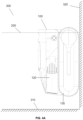
device 100 as shown inFIGs. 2 and3 , when the movingdevice 100 needs to be switched from below the liquid surface to above the liquid surface, the movingdevice 100 may move to a position close to theliquid surface 200 and determine when to control thebuoyancy cavity pump 1112 to inject gas into thebuoyancy cavity 1111. For more information about when the movingdevice 100 needs to be switched from below the liquid surface to above the liquid surface, please refer toFIG. 10 and its related description. As shown inFIG. 4A , when the movingdevice 100 needs to be switched from below the liquid surface to above the liquid surface, the movingdevice 100 may move against theside wall 320 of thetarget region 300 to a position close to theliquid surface 200 and determine when it is necessary to control the buoyancy force adjustment member to increase the volume of gas in thebuoyancy cavity 1111. For more information about the movement of the movingdevice 100 against theside wall 320 of thetarget region 300, please refer to the following part of the present disclosure. In some embodiments, when the movingdevice 100 needs to be switched from below the liquid surface to above the liquid surface, the movingdevice 100 may also move to a position close to theliquid surface 200 based on a first drive force generated by afirst propeller 112 and determine when the buoyancy force adjustment member needs to be controlled to increase the volume of gas in the buoyancy cavity. For more information about thefirst propeller 112 and the first drive force, please refer to the following part of the present disclosure. - In some embodiments, the moving
device 100 may include a first sensor (not shown). The first sensor may be configured to determine the position of the movingdevice 100 in real time. The aforementioned position may include a vertical position (or depth) of the movingdevice 100 in the liquid. For example, the first sensor may be provided at a central position of the moving device, and the aforementioned position may be a depth of the central position of the movingdevice 100 in the liquid. The first sensor may include, but is not limited to, a pressure sensor, an ultrasonic sensor, an optical sensor, etc. - In some embodiments, the moving
device 100 may also include a processor (not shown). The processor may be a microcontroller, an embedded processor, or an application-specific integrated circuit (ASIC), etc. The processor may obtain various data information of the movingdevice 100 and analyze and process the data information to control the various components in the movingdevice 100. When the movingdevice 100 needs to be switched from below the liquid surface to above the liquid surface, the processor may obtain the position of the movingdevice 100 in real time from the first sensor, and when the position of the movingdevice 100 meets a preset condition, the processor may control the buoyancy force adjustment member to increase the volume of the gas in thebuoyancy cavity 1111. The preset condition may include a position of the movingdevice 100 above a preset height. When the depth of the liquid in thetarget region 300 is fixed, the processor may determine whether theair inlet 1113 in the movingdevice 100 is above theliquid surface 200 by determining whether the position of the movingdevice 100 meets the preset condition. When the position of the movingdevice 100 shown inFIG. 4A meets the preset condition, the processor may determine that theair inlet 1113 on the movingdevice 100 is above theliquid surface 200, and the processor may control thebuoyancy cavity pump 1112 to discharge the liquid in thebuoyancy cavity 1111, and the air may enter thebuoyancy cavity 1111 through theair inlet 1113, so that the volume of the gas in thebuoyancy cavity 1111 can be increased and the buoyancy force of the movingdevice 100 can be increased. When the buoyancy force of the movingdevice 100 in the vertical direction is greater than the gravity of the movingdevice 100, the movingdevice 100 as shown inFIG. 4A may be switched to the movingdevice 100 as shown inFIG. 4B . - In some embodiments, the moving
device 100 may also include a second sensor (not shown). The second sensor may be configured to detect in real time whether the air inlet of thebuoyancy cavity 1111 is positioned in air. For example, the second sensor may include an ultrasonic sensor. The second sensor may be provided at the position of the air inlet of thebuoyancy cavity 1111. In some embodiments, the second sensor may also be provided at other positions of the movingdevice 100 and obtain a detection result of whether the air inlet is located in the air by a position transition. In some embodiments, when the movingdevice 100 needs to be switched from below the liquid surface to above the liquid surface, the processor may obtain a detection result of whether the air inlet of thebuoyancy cavity 1111 is located in the air, and when the detection result characterizes that the aforementioned air inlet is located in the air, the buoyancy force adjustment member is controlled to increase the volume of the gas in thebuoyancy cavity 1111 to achieve the switching of the movingdevice 100 from below the liquid surface to above the liquid surface. For more information about the processor controlling the buoyancy force adjustment member to increase the volume of gas in thebuoyancy cavity 1111 to enable the movingdevice 100 to be switched from below the liquid surface to above the liquid surface, please refer to the above section of the present disclosure. - When the moving
device 100 needs to be switched from above the liquid surface to below the liquid surface, the processor may control the buoyancy force adjustment member to reduce the volume of gas in thebuoyancy cavity 1111. For more information about when the movingdevice 100 needs to be switched from above the liquid surface to below the liquid surface, please refer toFIG. 10 and its related description. As shown inFIGs. 2 and3 , the processor may discharge gas from thebuoyancy cavity 1111 via theconnection pipeline 1114, thereby reducing the volume of the gas in thebuoyancy cavity 1111 to reduce the buoyancy force to allow the movingdevice 100 to be switched from above the liquid surface to below the liquid surface. - In some embodiments of the present disclosure, the buoyancy
force adjustment component 111 may be provided to adjust the magnitude of the buoyancy force to which the movingdevice 100 is subjected in the vertical direction, thereby achieving flexible switching of the movingdevice 100 above the liquid surface and below the liquid surface, and improving the efficiency and reliability of the movingdevice 100 in the liquid environment. By providing the first sensor or the second sensor, the movingdevice 100 can automatically determine the environment in which theair inlet 1113 is located, which improves the efficiency of the use of the movingdevice 100. - In some embodiments, the
mode switching member 110 may also include a power adjustment assembly. The power adjustment assembly may be configured to adjust the first drive force to which the movingdevice 100 is subjected in the vertical direction. The power adjustment assembly may be a variety of structures that can provide the first drive force. For example, the power adjustment assembly may include a propeller, and the aforementioned propeller may be provided vertically on the movingdevice 100, and by rotating the aforementioned propeller, the movingdevice 100 may be made to obtain the first drive force in the vertical direction. The first drive force in the vertical direction may be upward or downward, and under the action of the first drive force, the movingdevice 100 may move upward or downward in the vertical direction, or be suspended in a certain position in the liquid. - In some embodiments, as shown in
FIG. 5 , the power adjustment assembly may include thefirst propeller 112. Thefirst propeller 112 may be configured to propel the liquid in a first preset direction. The first preset direction may be a direction in which thefirst propeller 112 discharges the liquid. When thefirst propeller 112 propels the liquid in the first preset direction, the movingdevice 100 may be subjected to a reaction force opposite to the first preset direction, and the aforementioned reaction force may include the first drive force. It should be understood that since the movingdevice 100 needs to obtain the first drive force in the vertical direction, the first preset direction includes at least an inclination in the vertical direction to ensure that the obtained reaction force as mentioned before has a division force in the vertical direction (i.e., the first drive force). Accordingly, an angle between the first preset direction and the vertical direction may be [0°, 90°). - The magnitude of the first drive force may be positively correlated with the speed of the liquid moving along the first preset direction. The greater the speed of the liquid moving in the first preset direction is, the greater the reaction force on the moving
device 100 opposite to the first preset direction is, and the greater the first drive force in the vertical direction is. - The magnitude of the first drive force may also be negatively correlated with the angle between the first preset direction and the vertical direction. When the liquid moves along the first preset direction with the same speed, the greater the angle between the first preset direction and the vertical direction is, the smaller the first drive force of the moving
device 100 in the vertical direction is. As shown inFIG. 7A , when the angle between the first preset direction and the vertical direction is 0°, the aforementioned reaction force on the movingdevice 100 may be completely converted to the first drive force in the vertical direction. - The moving
device 100 may include one or morefirst propellers 112. Thefirst propeller 112 may be provided at various positions in the movingdevice 100. As shown inFIG. 5 andFIG. 7A , thefirst propeller 112 may be vertically provided in the central position of the movingdevice 100 to ensure the balance during the movement of the movingdevice 100. Thefirst propeller 112 may include animpeller 1121 and amotor assembly 1122. Theimpeller 1121 may drive the liquid in the first preset direction by rotation, and when the liquid moves in the first preset direction, the movingdevice 100 is subjected to the first drive force in the vertical direction. Themotor assembly 1122 may power theaforementioned impeller 1121. As shown inFIG. 7A , thefirst propeller 112 in the movingdevice 100 may include twoopenings 1123. Oneopening 1123 of thefirst propeller 112 may be located at a top of the movingdevice 100, and anotheropening 1123 of thefirst propeller 112 may be located at a bottom of the movingdevice 100. Theimpeller 1121 may be driven by themotor assembly 1122 to absorb the liquid from one of the twoopenings 1123 and discharge the liquid from theother opening 1123, thereby giving the movingdevice 100 the first drive force in the vertical direction. When the movingdevice 100 is located in the liquid, the movingdevice 100 may also adjust the rotation direction of the impeller 1121 (e.g., forward rotation, counter rotation) to adjust the first preset direction, thereby adjusting the direction of the first drive force, so that the position of the movingdevice 100 above the liquid surface and below the liquid surface may be switched. - Some embodiments of the present disclosure, by providing the
first propeller 112, can make it possible for the movingdevice 100 to quickly and easily switch the position of the movingdevice 100 above the liquid surface and below the liquid surface. - In some embodiments, the moving
device 100 may also move in a horizontal direction of thetarget region 300. As shown inFIG. 2 andFIG. 5 , the movingdevice 100 may also include asecond propeller 120. Thesecond propeller 120 may propel the liquid in a second preset direction to generate a second drive force in the horizontal direction. The movingdevice 100 may achieve a movement in the horizontal direction under the action of the second drive force. The second preset direction may include a direction in which thesecond propeller 120 discharges the liquid. Similarly to thefirst propeller 112, since the movingdevice 100 needs to obtain the second drive force in the horizontal direction, the second preset direction includes at least an inclination in the horizontal direction to ensure that the obtained reaction force as mentioned before has a division force in the horizontal direction (i.e., the second drive force). Accordingly, an angle between the second preset direction and the horizontal direction may [0°, - 90°). - Similar to the
first propeller 112, the magnitude of the second drive force may be positively correlated with a speed of the liquid moving in the second preset direction. The greater the speed of the liquid moving in the second preset direction is, the greater the reaction force on the movingdevice 100 opposite to the second preset direction is, and the greater the second drive force in the horizontal direction is. The magnitude of the second drive force may also be negatively correlated with the angle between the second preset direction and the horizontal direction. The greater the angle between the second preset direction and the horizontal direction is, the smaller the second drive force of the movingdevice 100 in the horizontal direction is when the liquid is moving at the same speed along the second preset direction. As shown inFIG. 7A , when the angle between the second preset direction and the horizontal direction is 0°, the aforementioned reaction force on the movingdevice 100 may completely switch the second drive force on the movingdevice 100 in the horizontal direction. - Similar to the
first propeller 112, thesecond propeller 120 may include an impeller and a motor assembly. For more information about the impeller and the motor assembly, please refer to the above section of the present disclosure. - The moving
device 100 may include one or moresecond propellers 120. Thesecond propeller 120 may be provided at a bottom of the movingdevice 100. For example, when only onesecond propeller 120 is included in the movingdevice 100, thesecond propeller 120 may be provided horizontally at a central position at the bottom of the movingdevice 100 to ensure the balance of the movingdevice 100. In some embodiments, thesecond propeller 120 may also be provided on a side of the movingdevice 100. It should be noted that when thesecond propeller 120 is provided on the side of the movingdevice 100, its setting position should be at least partially below a floating position of the movingdevice 100 on the liquid surface to ensure that when the movingdevice 100 is floating on the liquid surface, the impeller rotation in thesecond propeller 120 can propel the liquid in the second preset direction, to provide the second drive force in the horizontal direction for the movingdevice 100. In some embodiments, when thesecond propeller 120 is provided on the side of the movingdevice 100, the setting position of thesecond propeller 120 may be all below the floating position of the movingdevice 100 on the liquid surface. In some embodiments, at least onesecond propeller 120 may be provided on each of a left side and a right side of the movingdevice 100. As shown inFIG. 5 , onesecond propeller 120 may be provided on each of the left and right side of the movingdevice 100. When the movingdevice 100 moves in the liquid, the movingdevice 100 may adjust the power of the motor assembly of each of thesecond propellers 120 on the left side and the right side, respectively, to adjust a movement speed of each of thesecond propellers 120 on the left side and the right side to push the liquid along the second preset direction, to achieve a turn of the movingdevice 100. For example, when the movement speed of thesecond propeller 120 on the left side propelling the liquid in the second preset direction is greater than the movement speed of thesecond propeller 120 on the right side propelling the liquid in the second preset direction, the movingdevice 100 may turn toward the right side under the action of thesecond propeller 120 on the left side. - In some embodiments of the present disclosure, by providing the
second propeller 120, it is possible to switch the position of the movingdevice 100 in the horizontal direction, for example, to go straight or turn in the horizontal direction, so that the function of the movingdevice 100 can be expanded to make it suitable for more use scenarios. - In some embodiments, the moving
device 100 may also include atrack 130. The operation of thetrack 130 may drive the movement of the movingdevice 100. - The
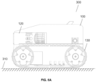
track 130 may drive the movingdevice 100 in the horizontal direction. As shown inFIG. 6A , when the movingdevice 100 is located on thebottom wall 310 of thetarget region 300, the operation of thetrack 130 may drive the movingdevice 100 on thebottom wall 310. - The
track 130 may also drive the movingdevice 100 in the vertical direction. As shown inFIGs. 4A and6C , the operation of thetrack 130 also drives the movingdevice 100 on theside wall 320 of thetarget region 300 when the movingdevice 100 is pressed against theside wall 320. For more information about how the movingdevice 100 is achieved by pressing against theside wall 320 of thetarget region 300, please refer to the following part of the present disclosure. - In some embodiments, the
track 130 may also enable a transition of a moving region of the movingdevice 100 from thebottom wall 310 to theside wall 320. As shown inFIG. 6B , when thetrack 130 moves to a point where thebottom wall 310 meets theside wall 320, a portion of thetrack 130 moves on theside wall 320 and a portion moves on thebottom wall 310. A portion of thetrack 130 at theside wall 320 may drive the movingdevice 100 upward until the moving region of the movingdevice 100 transitions from thebottom wall 310 to theside wall 320. When the moving region of the movingdevice 100 is converted from thebottom wall 310 to theside wall 320, the movingdevice 100 may move on theside wall 320 driven by thetrack 130, the movingdevice 100 may also move on theside wall 320 under the action of the second drive force provided by thesecond propeller 120 after steering, and the movingdevice 100 may also move on theside wall 320 based on the action of a third drive force provided by amain water pump 140. For more information about themain water pump 140 and the third drive force, please refer to the following part of the present disclosure. - Some embodiments of the present disclosure can facilitate the movement of the moving
device 100 in various positions in the liquid by providing thetrack 130 and enable the transition of the moving region of the movingdevice 100 from thebottom wall 310 to theside wall 320. - In some embodiments, the moving
device 100 may also include themain water pump 140. Themain water pump 140 may be configured to drive the movingdevice 100 to absorb the liquid from a water inlet and discharge it from a water outlet. The water inlet may include one or more inlets for the liquid to enter the movingdevice 100. As shown inFIG. 5 ,FIG. 7A ,FIG. 7B , andFIG. 8 , the mainwater pump inlet 141 in the movingdevice 100 may serve as an inlet (i.e., a water inlet) for the liquid to enter the inside of the movingdevice 100. The water outlet may include one or more outlets in the movingdevice 100 where the liquid leaves the movingdevice 100 and enters thetarget region 300. As shown inFIG. 5 ,FIG. 7A ,FIG. 7B , andFIG. 8 , the mainwater pump outlet 142 in the movingdevice 100 may serve as an outlet (i.e., a water outlet) for the liquid in the movingdevice 100 to leave the movingdevice 100 and enter thetarget region 300. - Similar to the
first propeller 112, themain water pump 140 may also include an impeller with a motor assembly, and the impeller may be driven by the motor assembly to rotate, to absorb the liquid in thetarget region 300 from the water inlet and discharge the liquid in the movingdevice 100 to thetarget region 300 through the water outlet. In some embodiments, the movingdevice 100 may switch the function of the mainwater pump inlet 141 and the mainwater pump outlet 142 by adjusting a rotation direction of the impeller in themain water pump 140. For example, when the impeller in themain water pump 140 is counter-rotating, the mainwater pump inlet 141 may be configured for the liquid to discharge and the mainwater pump outlet 142 may be configured for the liquid to enter. - In some embodiments, when the moving
device 100 is located on theside wall 320, the water outlet (e.g., the main pump outlet 142) may be oriented at least within thetarget region 300 and parallel to a horizontal direction or with a downward slope in a vertical direction, thereby guaranteeing that when themain water pump 140 is in operation and the liquid is discharged from themain pump outlet 142, the movingdevice 100 may receive the third drive force to drive the movingdevice 100 to press against theside wall 320. The third drive force may include a reaction force obtained by the movingdevice 100 when themain water pump 140 discharges the liquid from the mainwater pump outlet 142. When themain pump outlet 142 is oriented inside thetarget region 300 and parallel to the horizontal direction, the third drive force obtained by the movingdevice 100 is oriented vertically towards theside wall 320, so that the movingdevice 100 may be made to press against theside wall 320. In some embodiments, when the movingdevice 100 needs to move on theside wall 320, the mainwater pump outlet 142 may be directed within thetarget region 300. When there is a downward slope in the vertical direction, on the one hand, the third drive force obtained by the movingdevice 100 may exist a component force in the horizontal direction towards theside wall 320, which may cause the movingdevice 100 to press against theside wall 320; on the other hand, the aforementioned third drive force may also exist a component force in the vertical direction with an upward division force, thereby also allowing the movingdevice 100 to move upwardly along theside wall 320. When the movingdevice 100 is located on thebottom wall 310, the third drive force obtained by themain water pump 140 discharging through the aforementioned mainwater pump outlet 142 may also exist a component force in the horizontal direction, thereby also allowing the movingdevice 100 to move on thebottom wall 310. - In some embodiments, the main
water pump inlet 141 may be provided at the bottom of the movingdevice 100. When the movingdevice 100 needs to move on theside wall 320, themain water pump 140 may absorb the liquid from the mainwater pump inlet 141 to obtain a fourth drive force to drive the movingdevice 100 to press against theside wall 320. The fourth drive force may include an absorption force generated by themain water pump 140 from the mainwater pump inlet 141, and the aforementioned absorption force may drive the movingdevice 100 to press against theside wall 320. - In some embodiments, when the moving
device 100 needs to move on theside wall 320, themain water pump 140 in the movingdevice 100 may drive the movingdevice 100 to press against theside wall 320. At least one of thetrack 130, thesecond propeller 120, and themain water pump 140 in the movingdevice 100 may provide a driving force upward in the vertical direction to drive the movingdevice 100 move upward on the side wall, and at least one of thetrack 130 and thesecond propeller 120 may provide a driving force downward in the vertical direction to drive the movingdevice 100 to move downward on the side wall. - Some embodiments of the present disclosure can make the moving
device 100 presses against theside wall 320 by providing themain water pump 140, thus limiting the movingdevice 100, facilitating the moving of the movingdevice 100 on theside wall 320, and completing the position change of the movingdevice 100 from below the liquid surface to above the liquid surface. - It should be noted that the above description of the moving
device 100 and its individual components is for descriptive convenience only and does not limit the present disclosure to the scope of the embodiments cited. It can be understood that it is possible for those skilled in the art, with an understanding of the principle of the device, to make any combination of the individual members or to form subcomponents to connect to other members without departing from this principle. -
FIG. 8 is a schematic diagram illustrating a pool cleaning robot according to some embodiments of the present disclosure. - The
pool cleaning robot 400 may be configured to clean the pool. In some embodiments, thepool cleaning robot 400 may include a movingdevice 100, adust box 410, and a control member. Thedust box 410 may be configured for a water surface cleaning and an in-water cleaning of the pool. The control member in the aforementionedpool cleaning robot 400 controls the movingdevice 100 to switch positions in the water surface of the pool and underwater to achieve the water surface cleaning or underwater cleaning. - As shown in
FIGs. 8 and9 , thedust box 410 may include one or more dust box openings. The dust box opening may be configured for an entrance of trash or other impurities from the pool into thepool cleaning robot 400. - In some embodiments, the dust box opening may include a water surface
dust box opening 411. The water surfacedust box opening 411 may be configured as an entrance for the trash or impurities from the pool water surface to enter thedust box 410. The water surfacedust box opening 411 may be provided on a side (e.g., front side) of thepool cleaning robot 400 and contain a floating position of thepool cleaning robot 400 when thepool cleaning robot 400 floats on the water surface, so that the trash or other impurities on the pool water surface may pass through the water surfacedust box opening 411 into thedust box 410 with the liquid. For example, the floating position of thepool cleaning robot 400 while thepool cleaning robot 400 floats on the water surface may be located at a midline position or a 1/3 position of the water surfacedust box opening 411. - In some embodiments, the dust box opening may also include a in-water
dust box opening 412. The in-waterdust box opening 412 may be configured as an entrance for the trash or impurities in the pool water to enter thedust box 410. The in-waterdust box opening 412 may be provided below the floating position of thepool cleaning robot 400 at the water surface. For example, the in-waterdust box opening 412 may be provided on a bottom of thepool cleaning robot 400. As another example, the in-waterdust box opening 412 may also be provided on a side edge of thepool cleaning robot 400 below the floating position on the water surface. - Some embodiments of the present disclosure extend the use scenarios of the
pool cleaning robot 400 and enhance the user experience by providing the water surfacedust box opening 411 and the in-waterdust box opening 412 to enable thepool cleaning robot 400 to perform the water surface cleaning and the in-water cleaning. - The
dust box 410 may also include a dust boxroller brush assembly 413. Thedust box 410 may include one or more dust boxroller brush assemblies 413. The dust boxroller brush assembly 413 may be configured to improve the efficiency of the water surface cleaning by entraining the trash or impurities from the water surface into thedust box 410 when performing pool water surface cleaning. The dust boxroller brush assembly 413 may be provided in the water surfacedust box opening 411. As shown inFIG. 7B , the dust boxroller brush assembly 413 may be provided on an inside of the water surfacedust box opening 411. In some embodiments, the dust boxroller brush assembly 413 may also be provided outside of or on the water surfacedust box opening 411. - In some embodiments, the
dust box 410 may also include acover plate 414 of the water surface dust box opening and acover plate 415 of the in-water dust box opening. Thecover plate 414 of the water surface dust box opening is configured to adjust an opening and closing state of the water surfacedust box opening 411. When the water surfacedust box opening 411 is open, the liquid on the water surface of the pool may enter thedust box 410 through the water surfacedust box opening 411; when the water surfacedust box opening 411 is closed, the liquid on the pool water cannot enter thedust box 410 through the water surfacedust box opening 411. Thecover plate 414 of the water surface dust box opening is provided on the water surfacedust box opening 411. As shown inFIG. 9 , thecover plate 414 of the water surface dust box opening may be provided in the water surfacedust box opening 411. Thecover plate 414 of the water surface dust box opening may also be provided on the inside of the water surfacedust box opening 411, or on the outside of the water surfacedust box opening 411. Similar to thecover plate 414 of the water dust box opening, thecover plate 415 of the in-water dust box opening is configured to adjust an opening and closing state of the in-waterdust box opening 412. Thecover plate 415 of the in-water dust box opening is provided on the in-waterdust box opening 412. Thecover plate 415 of the in-water dust box opening is provided in the in-waterdust box opening 412, on an inside of the in-waterdust box opening 412, or on an outside of the in-waterdust box opening 412. - The
cover plate 414 of the water surface dust box opening and thecover plate 415 of the in-water dust box opening may be movable members. The control member may allow the corresponding dust box opening or closing by adjusting the water dustbox opening cover 414 and/or the in-water dustbox opening cover 415. For example, the water surface dustbox opening cover 414 may be a rotatable member, and the control member may convert the water surface dust box opening 411 from a closing state to an opening state by rotation of the water surface dustbox opening cover 414. - In some embodiments, when the
pool cleaning robot 400 needs to perform the underwater cleaning, the control member may keep the surfacedust box mouth 411 closed through thecover plate 414 of the water dust box opening and keep the in-waterdust box opening 412 open through thecover plate 415 of the in-water dust box opening, which avoids the diversion of liquid by the water surfacedust box opening 411 and ensures the absorption of the in-waterdust box opening 412, thereby improving the cleaning efficiency of thepool cleaning robot 400 in the water. - In some embodiments, the
dust box 410 may also include other structures. For example, thedust box 410 may also include a filter. The aforementioned filter may be configured to filter the liquid entering thedust box 410. - The control member may be configured to control the
pool cleaning robot 400 for the water surface cleaning or underwater cleaning of the pool. In some embodiments, the control member may obtain a target task for cleaning a target pool, the target task including a water surface cleaning and an underwater cleaning; determine an adjustment parameter of the movingdevice 100 based on the target task and a current position of thepool cleaning robot 400; control the movingdevice 100 to move, based on the adjustment parameter, thepool cleaning robot 400 to a target position to complete the target task. For more information about the above embodiments, please refer toFIG. 10 and its related description. - Some embodiments of the present disclosure ensure a comprehensive pool cleaning by providing the
pool cleaning robot 400 with the movingdevice 100 to clean the pool in multiple positions such as the bottom, the water, and the surface of the pool in an all-round manner. - In some embodiments, the
pool cleaning robot 400 may also include atrash guiding member 420. Thetrash guiding member 420 may drive the trash in the liquid surface of the pool into the water surfacedust box opening 411. As shown inFIG. 8 andFIG. 9 , thetrash guiding member 420 may be located on an outside of the water surfacedust box opening 411 and be hollow inside. Thetrash guiding member 420 may be with a size of afirst end 421 away from the water surfacedust box opening 411 that is larger than a size of the water surfacedust box opening 411, and a size of asecond end 422 connected to the water surfacedust box opening 411 that is not smaller than the size of the water surfacedust box opening 411. Thetrash guiding member 420 may include, but is not limited to, structures such as a truncated cone, a trapezoid, etc., whose interior are hollow. - In some embodiments, the size of the
first end 421 may be provided in proportion to the water surfacedust box opening 411. For example, a size ratio of thefirst end 421 to the water surfacedust box opening 411 may be set no more than 10:1 to avoid too much trash or impurities entering the water surfacedust box opening 411 at the same time to cause the water surfacedust box opening 411 to clog. - Some embodiments of the present disclosure, by providing the
trash guiding member 420, can collect the trash on the wider water surface to enter the water surfacedust box opening 411, which avoids reducing the efficiency of the water surface cleaning of thepool cleaning robot 400 caused by the water surfacedust box opening 411 being too small. - As shown in
FIGs. 8 and9 , thepool cleaning robot 400 may also include amain roller brush 430. Themain roller brush 430 may be configured to clean thebottom wall 310 and theside wall 320 of the pool. Thepool cleaning robot 400 may include one or more main roller brushes 430. Themain roller brush 430 may be provided on the bottom and/or side of thepool cleaning robot 400. As shown inFIG. 8 , thepool cleaning robot 400 may be provided with onemain roller brush 430 at each of a front and rear end of the bottom of thepool cleaning robot 400. When thepool cleaning robot 400 moves across the bottom of the pool, themain roller brush 430 may clean the bottom of the pool (e.g., sweep for impurities or algae); when thepool cleaning robot 400 moves over the walls of the pool, themain roller brush 430 may also clean the walls of the pool. - It should be noted that the above description of the
pool cleaning robot 400 and its individual components is for descriptive convenience only and does not limit the present disclosure to the scope of the embodiments cited. It can be understood that it is possible for those skilled in the art, with an understanding of the principle of the device, to make any combination of the individual members or to form subcomponents to connect to other members without departing from this principle. -
FIG. 10 is a flowchart illustrating an exemplary liquid cleaning control method according to some embodiments of the present disclosure. Theprocess 1000 may be applied to thepool cleaning robot 400 and executed by the control member. As shown inFIG. 10 , theprocess 1000 may include the following steps. - In 1010, a target task for cleaning a target pool may be obtained.
- The target pool may be a pool that needs to be cleaned. The target task may be a cleaning task that needs to be performed on the target pool. The target task may include a water surface cleaning and/or an underwater cleaning. The water surface cleaning may refer to cleaning the water surface of the target pool, and the underwater cleaning may refer to cleaning the underwater (e.g., the water body, the walls of the pool, etc.) of the target pool. In some embodiments, the target task may also include a specific cleaning site. For example, the underwater cleaning may also include, but is not limited to, a water body cleaning, a pool bottom cleaning, an individual pool wall cleaning, etc.
- The control member may obtain the target task in a variety of ways. For example, the control member may obtain a target task input by a user. As another example, the control member can be set to perform the target task at regular intervals, e.g., once every 3 days for the water surface cleaning and once every 2 days for the underwater cleaning. As another example, the
pool cleaning robot 400 may also include a detection member, and the aforementioned detection member may test the water quality of the target pool and obtain water quality data of the target pool. The control member may obtain the aforementioned water quality data, and determine the target task based on the water quality data. The water quality data may be data that reflect a water quality condition of the target pool. The water quality data includes, but is not limited to, a picture of the water surface of the target pool, a picture of the water, a picture of the individual pool walls, etc. The control member may input the water quality data into a task determination model, and an output of the task determination model may include the target task. The task determination model may analyze the water quality data of the target pool to determine the cleanliness (e.g., clarity, algae distribution, impurities, etc.) of each region (e.g., water surface, water, individual pool walls, etc.) and thus determine the corresponding target task. The task determination model may include a convolutional neural network model, a graph neural network, or any other machine learning model that can implement this function. The task determination model may be obtained by training based on multiple sets of training samples with labels. The training samples may include sample water quality data from a sample pool, and the labels may include a sample task. The sample task may be obtained by manually labeling the sample water quality data. - In 1020, an adjustment parameter of the moving device may be determined based on the target task and a current position of the pool cleaning robot.
- The control member may obtain the current position of the
pool cleaning robot 400, and for more information about obtaining the current position of thepool cleaning robot 400, please refer to the first sensor above in the present disclosure. - The adjustment parameter may include route information for moving from the current position to a position of the target pool where the target task needs to be performed and route information required to complete the target task.
- The control member may determine a starting position in the target pool where the target task needs to be performed based on the target task, determine the route information for the
pool cleaning robot 400 to move from the current position to the position of the target pool where the target task needs to be performed based on the aforementioned starting position and the current position, and then determine the route information required to complete the target task based on the target task of the target pool, thereby determining the adjustment parameter of the movingdevice 100. - In 1030, the moving device may be controlled, based on the adjustment parameter, to drive the pool cleaning robot to move and clean to accomplish the target task.
- The control member may control the moving
device 100 to drive thepool cleaning robot 400 to move from the current position to the starting position where the target task needs to be performed based on the route information in the adjustment parameter for moving from the current position to the position of the target pool where the target task needs to be performed, and then open thedust box 410 in thepool cleaning robot 400 and themain roller brush 430 for cleaning to complete the target task based on the route information in the adjustment parameter, thereby completing the target task. Thepool cleaning robot 400 may stay at an ending position, return to the starting position before moving, or a preset default position after completing the target task. - Some embodiments of the present disclosure enable control of the
pool cleaning robot 400 to clean all parts of the pool through the aforementioned liquid cleaning control method to improve pool cleaning efficiency while ensuring the comprehensive pool cleaning. - It should be noted that the above description of the
process 1000 is merely provided for the purpose of illustration, and is not intended to limit the scope of the present disclosure. For those skilled in the art, various amendments and changes can be made to theprocess 1000 under the guidance of the present disclosure. However, these modifications and changes are still within the scope of the present disclosure. - Some embodiments of the present disclosure also provide a non-transitory computer-readable storage medium. The storage medium may include a set of instructions. When the set of instructions are executed by a processor, a liquid cleaning control method as described above is implemented.
- The basic concept has been described above. Obviously, for the technicians of the arts, the above-mentioned detailed disclosure is only used as an example, and it does not constitute a limitation of the present disclosure. Although not explicitly described herein, various modifications, improvements, and corrections to the present disclosure may occur to those skilled in the art. The amendments, improvements, and amendments are recommended in the present disclosure, so the amendments, improvements, and amendments of this class still belong to the spirit and scope of the demonstration embodiments of the present disclosure.
- Meanwhile, the present disclosure uses specific words to describe the embodiments of the present disclosure. For example, "one embodiment," "an embodiment," and/or "some embodiments" mean that a certain feature, structure, or characteristic is connected with at least one embodiment of the present disclosure. Therefore, it should be emphasized and noted that two or more references of "an embodiment" or "one embodiment" or "an alternative embodiment" in various places in the present disclosure do not necessarily refer to the same embodiment. Further, certain features, structures, or features of one or more embodiments of the present disclosure may be combined.
- Furthremore, unless expressly stated in the claims, the order or elements and sequences of treatment, the use of alphanumeric numbers, or other names described in this description shall not be configured to define the order of processes and methods in the present disclosure Although the above disclosure discusses through various examples what is currently considered to be a variety of useful embodiments of the disclosure, it is to be understood that such detail is solely for that purpose of description and that the appended claims are not limited to the disclosed embodiments, on the contrary, are intended to cover modifications and equivalent combination s that are within the spirit and scope of the embodiments of the present disclosure. For example, although the implementation of various components described above may be embodied in a hardware device, it may also be implemented as a software only solution, e.g., an installation on an existing server or mobile device.
- Similarly, it should be noted that to simplify the expressions disclosed in the present disclosure and thus help the understanding of one or more embodiments of the invention, in the foregoing description of the embodiments of this specification, various features may sometimes be combined into one embodiment, drawings or descriptions thereof. However, this approach of disclosure does not imply that the features required by the present disclosure are more than the features recited in the claims. Rather, claimed subject matter may lie in less than all features of a single foregoing disclosed embodiment.
- Some embodiments use numbers with description ingredients and attributes. It should be understood that the number described by such examples is used in some examples with the modified words "about," "approximate," or "generally" to modify. Unless stated otherwise, "about," "approximately," or "substantially" means that a variation of ±20% is allowed for the stated number. Accordingly, in some embodiments, the numerical parameters set forth in the written description and attached claims are approximations that may vary depending upon the desired properties sought to be obtained by a particular embodiment. In some embodiments, the numerical parameters should be construed in light of the number of reported significant digits and by applying ordinary rounding techniques. Notwithstanding that the numerical ranges and parameters setting forth the broad scope of some embodiments of the application are approximations, the numerical values set forth in the specific examples are reported as precisely as practicable.
- Each of the patents, patent applications, publications of patent applications, and other material, such as articles, books, specifications, publications, documents, things, and/or the like, referenced herein is hereby incorporated herein by this reference in its entirety for all purposes, excepting any prosecution file history associated with same, any of same that is inconsistent with or in conflict with the present document, or any of same that may have a limiting affect as to the broadest scope of the claims now or later associated with the present document. It should be noted that, if there is any inconsistency or conflict between the descriptions, definitions, and/or usage of terms in subsidiary information of the present disclosure and the contents of the present disclosure, the descriptions, definitions, and/or usage of terms in the present disclosure shall prevail.
- Finally, it should be understood that the embodiments described in the present disclosure are only configured to illustrate the principles of the embodiments of the present disclosure. Other modifications that may be employed may be within the scope of the present disclosure. Therefore, as an example and not a limitation, alternative configurations of the embodiments of the present disclosure may be regarded as consistent with the teaching of the present disclosure. Correspondingly, the embodiments of the present disclosure are not limited to the embodiments clearly introduced and described in the present disclosure.
- The present invention provides a moving device used in liquid, comprising:
a mode switching member configured to achieve a position switching of the moving device above a liquid surface and below the liquid surface, wherein when the moving device is below the liquid surface, the moving device is fully submerged below the liquid surface, and when the moving device is above the liquid surface, at least a portion of the moving device is above the liquid surface. - The moving device as above, wherein the mode switching member is further configured to adjust an action force received by the moving device in a vertical direction.
- The moving device as above,, wherein an action force received by the moving device in a vertical direction includes a buoyancy force to which the moving device is subjected in the vertical direction, and the mode switching member includes:
a buoyancy force adjustment assembly configured to adjust a magnitude of the buoyancy force to which the moving device is subjected in the vertical direction. - The moving device as above, wherein the buoyancy force adjustment assembly includes:
- a buoyancy cavity configured to accommodate liquid and/or gas;
- a buoyancy force adjustment member configured to adjust a volume of the gas in the buoyancy cavity.
- The moving device as above, further comprising:
- a first sensor configured to sense a position of the moving device;
- a processor configured to:
- obtain the position of the moving device when the moving device needs to be switched from under the liquid surface to above the liquid surface; and
- control the buoyancy force adjustment member to increase the volume of the gas in the buoyancy cavity when the position of the moving device meets a preset condition.
- The moving device as above, further comprising:
- a second sensor configured to detect whether a position of an air inlet of the buoyancy cavity is located in air;
- a processor configured to:
- obtain a detection result of whether the air inlet is located in air when the moving device needs to be switched from below the liquid surface to above the liquid surface; and
- control the buoyancy force adjustment member to increase the volume of the gas in the buoyancy cavity when the detection result indicating that the air inlet is located in air.
- The moving device as above, further comprising a processor configured to:
control the buoyancy force adjustment member to reduce a volume of gas in the buoyancy cavity when the moving device needs to be switched from above the liquid surface to below the liquid surface. - The moving device as above, wherein an action force received by the moving device in a vertical direction includes a first drive force to which the moving device is subjected in the vertical direction, and the mode switching member includes:
a power adjustment assembly configured to adjust the first drive force to which the moving device is subjected in the vertical direction. - The moving device as above, wherein the power adjustment assembly includes:
a first propeller configured to propel the liquid to move along a first preset direction, the moving device being subjected to the first drive force in the vertical direction when the liquid moves along the first preset direction, wherein a magnitude of the first drive force is positively correlated with a speed of the liquid moving along the first preset direction. - The moving device as above, wherein the first propeller includes:
- an impeller configured to drive the liquid by rotation to move along the first preset direction, the moving device being subjected to the first drive force in the vertical direction when the liquid moves along the first preset direction;
- a motor assembly configured to power the impeller.
- The moving device as above, further comprising:
a second propeller configured to propel the liquid to move along a second preset direction, the moving device being subjected to a second drive force in a horizontal direction when the liquid moves along the second preset direction, wherein a magnitude of the second drive force is positively correlated with a speed of the liquid moving along the second preset direction. - The moving device as above, wherein the moving device is provided with at least one second propeller on each of a left side and a right side in the horizontal direction.
- The moving device as above, wherein the moving device is configured to move in a target region including the liquid, the target region including a bottom wall and a side wall, and the moving device further including:
a track configured to drive the moving device to move and realize a transition of a moving region from the bottom wall to the side wall. - The moving device as above, further comprising:
a main water pump configured to drive the moving device to absorb the liquid from a water inlet and discharge the liquid from a water outlet. - The moving device as above, wherein the moving device is configured to move in a target region including the liquid, wherein the target region includes a bottom wall and a side wall, the water outlet includes a main water pump outlet, the main water pump outlet is oriented within the target region when the moving device is located on the side wall and parallel to the horizontal direction or has a downward slope in a vertical direction, and when the moving device needs to move on the side wall, the main water pump is also configured to:
discharge the liquid from the main water pump outlet, thus obtaining a third drive to drive the moving device tightly against the side wall. - The moving device as above, wherein the moving device is configured to move in the target region containing the liquid, wherein the target region includes the bottom wall and the side wall, the water inlet includes a main water pump inlet, the main water pump inlet is provided at a bottom of the moving device, and when the moving device needs to move on the side wall, the main water pump is further configured to:
absorb the liquid from the main pump inlet, thereby obtaining a fourth drive to drive the moving device tightly against the side wall. - A pool cleaning robot, comprising:
- a dust box including a dust box opening configured to clean liquid that enters the dust box;
- a moving device as above;
- a control member configured to control the pool cleaning robot to perform a water surface cleaning of a pool or an underwater cleaning of the pool.
- The pool cleaning robot as above, wherein the dust box opening includes:
a water surface dust box opening, provided on a side of the pool cleaning robot, including a floating position of the pool cleaning robot, and configured as an entrance of trash or impurities on a pool surface entering to the dust box. - The pool cleaning robot as above, wherein the dust box includes:
a dust box roller brush assembly, provided in the surface dust box opening, and configured to roll the trash or impurities from the pool surface into the dust box when the surface cleaning is performed. - The pool cleaning robot as above, wherein the dust box opening includes:
an in-water dust box opening, provided below the floating position of the pool cleaning robot on the water surface, and configured as an entrance of trash or impurities in pool water entering to the dust box. - The pool cleaning robot as above, wherein the dust box further includes:
- a cover plate of the water surface dust box opening, provided on the water surface dust box opening, and including a movable part configured to adjust an opening state of the water surface dust box opening and a closing state of the water surface dust box opening;
- a cover plate of the in-water dust box opening, provided on the in-water dust box opening and including a movable part configured to adjust an opening state of the in-water dust box opening and a closing state of the in-water dust box opening.
- The pool cleaning robot as above, further comprising:
a trash guiding member configured to drive the trash in a water surface of the pool into the water surface dust box opening, the trash guiding member being located on an outside of the water surface dust box opening and being hollow inside, a size of a first end of the trash guiding member away from the water surface dust box opening being larger than a size of the water surface dust box opening, and a size of a second end of the trash guiding member connected to the water surface dust box opening being not smaller than the size of the water surface dust box opening. - The pool cleaning robot of any one as above, further including:
a main roller brush, provided on a bottom of the pool cleaning robot and/or a side of the pool cleaning robot, and configured to clean a bottom wall of the pool and a side wall of the pool. - A liquid cleaning control method, applied to a pool cleaning robot as above, and performed by a control member, comprising:
- obtaining a target task for cleaning a target pool, wherein the target task includes a water surface cleaning and/or an underwater cleaning;
- determining an adjustment parameter of the moving device based on the target task and a current position of the pool cleaning robot; and
- controlling, based on the adjustment parameter, the moving device to drive the pool cleaning robot to move and clean to accomplish the target task.
- A non-transitory computer-readable storage medium, comprising a set of instructions, wherein when executed by a processor, a liquid cleaning control method as above is implemented.
Claims (15)
- A pool cleaning robot, comprising:a dust box (410),a water surface dust box opening (411) and an in-water dust box opening (412) provided on the dust box (410);the water surface dust box opening (411) configured as an entrance of trash on the water surface entering the dust box;the in-water dust box opening (412) configured as an entrance of trash in the water entering the dust box;a mode switching member (110), configured to achieve a position switching between above the water surface and below the water surface;wherein the mode switching member (110) comprising:a buoyancy force adjustment assembly (111), comprising a buoyancy cavity (1111) and a buoyancy force adjustment member, is configured to adjust the buoyancy magnitude of the pool cleaning robot;a first propeller (112), configured to generate a first drive force;wherein the position switching between above the water surface and below the water surface at least comprises thatthe pool cleaning robot moves to a position close to the water surface based on the first drive force generated by the first propeller (112);the buoyancy force adjustment member increase the volume of gas in the buoyancy cavity (1111).
- The pool cleaning robot of claim 1, wherein the first propeller (112) is provided with a first opening and a second opening, wherein the first opening provided on the top of the pool cleaning robot, the second opening provided on the bottom of the pool cleaning robot.
- The pool cleaning robot of claims 1 or 2, wherein the first propeller (112) is configured to propel the liquid in the first preset direction, so that the cleaning robot is subjected to a reaction force opposite to the first preset direction, wherein an angle between the first preset direction and the vertical direction is [0°, 90°).
- The pool cleaning robot of one of claims 1-3, further comprising a second propeller (120) provided on each of a left side and a right side of the pool cleaning robot, wherein the second propeller (120) is configured to propel the liquid in a second preset direction to generate a second drive force, so that the cleaning robot achieves a movement in the horizontal direction under the action of the second drive force; wherein an angle between the second preset direction and the horizontal direction is (-90°,0°].
- The pool cleaning robot of claim 4, wherein both of the first propeller (112) and the second propeller (120) are provided with an impeller and a motor assembly, the motor assembly is configured to power the impeller.
- The pool cleaning robot of one of claims 1-5, the buoyancy force adjustment assembly (111) further comprising an air inlet (1113) configured to supply gas into the buoyancy cavity (1111), wherein the air inlet (1113) is provided on the buoyancy cavity (1111) or on a housing of the pool cleaning robot or independent of the buoyancy cavity (1111).
- The pool cleaning robot of one of claims 1-6, further comprising a first sensor configured to detect the position of the pool cleaning robot, or a second sensor configured to detect whether the air inlet is positioned in air, or a detection member configured to test the water quality of the pool and obtain water quality data of the pool.
- The pool cleaning robot of one of claims 1-7, further comprising a cover plate of the water surface dust box opening (414) configured to adjust an opening or closing state of the water surface dust box opening (411), and a cover plate of the in-water dust box opening (415) configured to adjust an opening or closing state of the in-water dust box opening (412).
- The pool cleaning robot of one of claims 6-8,when the air inlet (1113) is located in the air, the buoyancy force adjustment member increases the volume of the gas in the buoyancy cavity (1111).
- The pool cleaning robot of one of claims 1-9, the buoyancy force adjustment assembly comprising two buoyancy cavities provided symmetrically on a left side and a right side of the pool cleaning robot.
- The pool cleaning robot of one of claims 1-10, the buoyancy cavity (1111) is made of a flexible material, and the buoyancy force adjustment member is configured to inject air into the buoyancy cavity through the air inlet (1113) to increase the volume of gas in the buoyancy cavity (1111).
- The pool cleaning robot of one of claims 1-11, the buoyancy cavity (1111) is made of a rigid material; and the buoyancy force adjustment member isconfigured to pump out the liquid in the buoyancy cavity (1111), and the gas enters the buoyancy cavity (1111) through the air inlet (1113), so that the volume of gas in the buoyancy cavity (1111) is increased.
- The pool cleaning robot of one of claims 1-12, further comprising a track (130) , configured to drive the pool cleaning robot to move.
- The pool cleaning robot of one of claims 1-13, the dust box (410) further comprising a dust box roller brush assembly (413), configured to entrain the trash from the water surface into the dust box (410) when performing pool water surface cleaning.
- The pool cleaning robot of claim 14, the dust box brush assembly (413) is provided on an inside or outside of the water surface dust box opening, or on the water surface dust box opening.
Priority Applications (1)
| Application Number | Priority Date | Filing Date | Title |
|---|---|---|---|
| EP25152420.3A EP4517465A3 (en) | 2023-04-27 | 2023-04-27 | Moving devices used in liquid and pool cleaning robots |
Applications Claiming Priority (3)
| Application Number | Priority Date | Filing Date | Title |
|---|---|---|---|
| PCT/CN2023/091116 WO2024221324A1 (en) | 2023-04-27 | 2023-04-27 | Walking apparatus for use in liquid, and swimming pool cleaning robot |
| EP25152420.3A EP4517465A3 (en) | 2023-04-27 | 2023-04-27 | Moving devices used in liquid and pool cleaning robots |
| EP23738415.1A EP4474597B1 (en) | 2023-04-27 | 2023-04-27 | Moving apparatus for use in liquid, and swimming pool cleaning robot |
Related Parent Applications (2)
| Application Number | Title | Priority Date | Filing Date |
|---|---|---|---|
| EP23738415.1A Division EP4474597B1 (en) | 2023-04-27 | 2023-04-27 | Moving apparatus for use in liquid, and swimming pool cleaning robot |
| EP23738415.1A Division-Into EP4474597B1 (en) | 2023-04-27 | 2023-04-27 | Moving apparatus for use in liquid, and swimming pool cleaning robot |
Publications (2)
| Publication Number | Publication Date |
|---|---|
| EP4517465A2 true EP4517465A2 (en) | 2025-03-05 |
| EP4517465A3 EP4517465A3 (en) | 2025-06-11 |
Family
ID=88806094
Family Applications (5)
| Application Number | Title | Priority Date | Filing Date |
|---|---|---|---|
| EP25152420.3A Pending EP4517465A3 (en) | 2023-04-27 | 2023-04-27 | Moving devices used in liquid and pool cleaning robots |
| EP23738415.1A Active EP4474597B1 (en) | 2023-04-27 | 2023-04-27 | Moving apparatus for use in liquid, and swimming pool cleaning robot |
| EP25184347.0A Pending EP4617821A3 (en) | 2023-04-27 | 2023-04-27 | Moving devices used in liquid and pool cleaning robots |
| EP24795527.1A Pending EP4703536A1 (en) | 2023-04-27 | 2024-02-05 | Locomotion apparatus used in liquid, and cleaning device |
| EP24796280.6A Pending EP4703538A1 (en) | 2023-04-27 | 2024-04-26 | Cleaning apparatus |
Family Applications After (4)
| Application Number | Title | Priority Date | Filing Date |
|---|---|---|---|
| EP23738415.1A Active EP4474597B1 (en) | 2023-04-27 | 2023-04-27 | Moving apparatus for use in liquid, and swimming pool cleaning robot |
| EP25184347.0A Pending EP4617821A3 (en) | 2023-04-27 | 2023-04-27 | Moving devices used in liquid and pool cleaning robots |
| EP24795527.1A Pending EP4703536A1 (en) | 2023-04-27 | 2024-02-05 | Locomotion apparatus used in liquid, and cleaning device |
| EP24796280.6A Pending EP4703538A1 (en) | 2023-04-27 | 2024-04-26 | Cleaning apparatus |
Country Status (7)
| Country | Link |
|---|---|
| US (3) | US11946282B1 (en) |
| EP (5) | EP4517465A3 (en) |
| CN (4) | CN117120696A (en) |
| AU (3) | AU2023206211B2 (en) |
| DE (1) | DE212023000399U1 (en) |
| ES (1) | ES3044083T3 (en) |
| WO (3) | WO2024221324A1 (en) |
Families Citing this family (22)
| Publication number | Priority date | Publication date | Assignee | Title |
|---|---|---|---|---|
| USD1049524S1 (en) * | 2022-08-12 | 2024-10-29 | Shenzhen Aiper Intelligent Co., Ltd. | Swimming pool cleaner |
| AU2024216658A1 (en) * | 2023-02-06 | 2025-09-04 | Xingmai Innovation Technology (Suzhou) Co., Ltd. | Cleaning device and cleaning device system |
| AU2024223538A1 (en) * | 2023-02-16 | 2025-10-02 | Xingmai Innovation Technology (Suzhou) Co., Ltd. | Cleaning device |
| US12516538B2 (en) * | 2023-04-27 | 2026-01-06 | Xingmai Innovation Technology (Suzhou) Co., Ltd. | Swimming pool robot and method for controlling swimming pool robot |
| AU2024262807A1 (en) | 2023-04-27 | 2025-08-21 | Xingmai Innovation Technology (Suzhou) Co., Ltd. | Moving apparatus, cleaning device, and cleaning device control method |
| EP4517465A3 (en) * | 2023-04-27 | 2025-06-11 | Xingmai Innovation Technology (Suzhou) Co., Ltd. | Moving devices used in liquid and pool cleaning robots |
| WO2025112487A1 (en) * | 2023-12-01 | 2025-06-05 | 星迈创新科技(苏州)有限公司 | Cleaning device |
| AU2024278571B1 (en) | 2024-01-05 | 2025-06-26 | Aiper Global Pte. Ltd. | Automatic pool cleaning apparatus |
| WO2025152809A1 (en) * | 2024-01-17 | 2025-07-24 | 星迈创新科技(苏州)有限公司 | Cleaning apparatus |
| WO2025201313A1 (en) * | 2024-03-25 | 2025-10-02 | 深圳库犸科技有限公司 | Cleaning robot |
| WO2025201201A1 (en) * | 2024-03-25 | 2025-10-02 | 深圳库犸科技有限公司 | Cleaning robot |
| CN222810545U (en) * | 2024-03-25 | 2025-04-29 | 深圳库犸科技有限公司 | Cleaning robot body and cleaning robot |
| CN223104240U (en) * | 2024-03-25 | 2025-07-15 | 深圳库犸科技有限公司 | Cleaning Robot |
| CN221972313U (en) * | 2024-03-25 | 2024-11-08 | 深圳库犸科技有限公司 | Cleaning Robot |
| WO2025237098A1 (en) * | 2024-05-11 | 2025-11-20 | 深圳库犸科技有限公司 | Cleaning robot |
| USD1108063S1 (en) * | 2024-05-22 | 2025-12-30 | Xingmai Innovation Technology (Suzhou) Co., Ltd. | Garbage collection box for swimming pool cleaner |
| WO2026016855A1 (en) * | 2024-07-15 | 2026-01-22 | 深圳库犸科技有限公司 | Cleaning robot, water-entry control method, control device, and readable storage medium |
| CN118933413A (en) * | 2024-07-23 | 2024-11-12 | 深圳市元鼎智能创新有限公司 | Method and apparatus for cleaning a pool |
| WO2026057067A1 (en) * | 2024-09-13 | 2026-03-19 | 深圳库犸科技有限公司 | Control method for cleaning robot, cleaning robot, and computer storage medium |
| CN120193699B (en) * | 2025-05-23 | 2025-08-29 | 杭州部蓝创新科技有限公司 | Water level positioning control system for pool wall cleaning machine based on handle inclination detection |
| CN120291740B (en) * | 2025-06-06 | 2025-08-08 | 浪涌未来机器人科技(苏州)有限公司 | Pool cleaning equipment and waterline cleaning methods |
| CN120844839B (en) * | 2025-09-19 | 2026-01-30 | 星迈创新科技(苏州)有限公司 | Pool robot control methods |
Citations (8)
| Publication number | Priority date | Publication date | Assignee | Title |
|---|---|---|---|---|
| WO1997049504A1 (en) | 1995-06-27 | 1997-12-31 | Henkin Melvyn Lane | Positive pressure automatic swimming pool cleaning system |
| US6294084B1 (en) | 1997-12-25 | 2001-09-25 | Melvyn L. Henkin | Electric powered automatic swimming pool cleaning system |
| CN111003111A (en) | 2019-12-31 | 2020-04-14 | 诺亚机器人(浙江)有限公司 | Water surface cleaning robot |
| US10738495B2 (en) | 2016-11-22 | 2020-08-11 | Aqua Products, Inc. | Self-propelled robotic pool cleaner and water skimmer |
| CN212507600U (en) | 2020-08-06 | 2021-02-09 | 苏州宝时得电动工具有限公司 | Swimming pool cleaning device |
| US20220220762A1 (en) | 2021-01-13 | 2022-07-14 | Hayward Industries, Inc. | Mobile Nozzles And Associated Systems For Cleaning Pools And Spas |
| US20220333394A1 (en) | 2014-09-03 | 2022-10-20 | Maytronics Ltd. | Controlling a movement of a pool cleaning robot |
| CN217925129U (en) | 2022-08-12 | 2022-11-29 | 深圳市元鼎智能创新有限公司 | Swimming pool cleaning robot |
Family Cites Families (35)
| Publication number | Priority date | Publication date | Assignee | Title |
|---|---|---|---|---|
| US6365039B1 (en) * | 1998-12-23 | 2002-04-02 | Melvyn L. Henkin | Positive pressure automatic swimming pool cleaning system |
| FR2925557B1 (en) * | 2007-12-21 | 2013-09-20 | Zodiac Pool Care Europe | IMMERSE SURFACE CLEANING APPARATUS WITH DISENSIBLE SALT CIRCUIT |
| CN201358597Y (en) * | 2009-02-05 | 2009-12-09 | 付桂兰 | Remote-control ordered swimming pool cleaning robot |
| US8623201B2 (en) * | 2009-08-31 | 2014-01-07 | Smartpool Llc | Pool cleaning vehicle having improved logic |
| US8869337B2 (en) * | 2010-11-02 | 2014-10-28 | Hayward Industries, Inc. | Pool cleaning device with adjustable buoyant element |
| KR101402318B1 (en) | 2012-12-04 | 2014-06-05 | 주식회사코어벨 | Underwater working robot |
| US9745767B2 (en) * | 2013-03-15 | 2017-08-29 | Hayward Industries, Inc. | Swimming pool pressure cleaner including automatic timing mechanism |
| KR101416657B1 (en) * | 2013-04-18 | 2014-07-14 | 서울과학기술대학교 산학협력단 | Swimming Pool Cleaning Bobot |
| ES2607640T3 (en) | 2013-09-11 | 2017-04-03 | Maytronics Ltd. | Pool cleaner robot that has movement capabilities in the water line |
| CN204093164U (en) | 2014-07-21 | 2015-01-14 | 赵立庚 | A kind of auto-control formula water surface well strainer |
| US9551535B2 (en) * | 2014-12-19 | 2017-01-24 | Robert M. Rodrick | Apparatus and method for cooling selected portions of swimming pool water |
| CN104790696B (en) * | 2015-04-03 | 2017-05-24 | 西南交通大学 | Omnibearing cleaning and filtering robot for swimming pool |
| WO2016196169A1 (en) * | 2015-06-01 | 2016-12-08 | Aqua Products, Inc. | Ramped pontoon for retrieving a pool cleaner |
| US9951537B2 (en) * | 2016-06-16 | 2018-04-24 | Hayward Industries, Inc. | Top-bottom pool cleaner including a nose |
| US10167650B2 (en) * | 2016-08-10 | 2019-01-01 | Aquatron Robotic Technology Ltd. | Concurrent operation of multiple robotic pool cleaners |
| WO2018048799A2 (en) * | 2016-09-06 | 2018-03-15 | Zodiac Pool Systems, Inc. | Buoyant automatic cleaners for spas and other water-containing vessels |
| EP3293325B1 (en) * | 2016-09-13 | 2021-08-25 | Maytronics Ltd. | A set of pool cleaning robots |
| US10494827B2 (en) * | 2017-11-28 | 2019-12-03 | Aquatron Robotic Technology Ltd. | Directional control of robotic pool cleaners |
| US10294686B1 (en) * | 2018-04-24 | 2019-05-21 | Water Tech, LLC | Rechargeable robotic pool cleaning apparatus |
| US20200001723A1 (en) * | 2018-06-27 | 2020-01-02 | Aqua Products, Inc. | Charging System for Submersible Autonomous Vehicle with Rechargeable Battery |
| CN111350383A (en) * | 2018-12-21 | 2020-06-30 | 宝时得科技(中国)有限公司 | Cleaning robot |
| EP3845723B1 (en) * | 2019-12-30 | 2023-06-07 | Maytronics Ltd. | Pool cleaning robot with pressure sensor diaphragm |
| DE102020104806B4 (en) * | 2020-02-24 | 2022-07-21 | Tunze Aquarientechnik Gmbh | Cleaning device with floating body |
| CN111155798B (en) * | 2020-03-02 | 2025-07-18 | 上饶市经纬自动化科技有限公司 | Swimming pool submerged floating and trash cleaning robot |
| CN114059811A (en) * | 2020-08-06 | 2022-02-18 | 苏州宝时得电动工具有限公司 | Swimming pool cleaning device |
| CN115711055A (en) * | 2021-08-22 | 2023-02-24 | 易家骝 | Structure of underwater cleaning equipment and control method thereof |
| CN113774874A (en) * | 2021-09-10 | 2021-12-10 | 明达实业(厦门)有限公司 | water surface cleaner |
| CN216484130U (en) | 2021-12-23 | 2022-05-10 | 周宸 | Intelligent river water sample collecting robot |
| CN114319955B (en) * | 2022-03-04 | 2022-05-31 | 深圳潜行创新科技有限公司 | A swimming pool automatic cleaning robot that can be translated laterally |
| CN114278129B (en) * | 2022-03-04 | 2022-06-21 | 深圳潜行创新科技有限公司 | Full-automatic swimming pool cleaning robot |
| CN114941458A (en) * | 2022-05-31 | 2022-08-26 | 广州城市理工学院 | Dredging device |
| CN218324137U (en) * | 2022-07-26 | 2023-01-17 | 佛山市顺德区一拓电气有限公司 | Swimming pool robot and cleaning device thereof |
| CN218467262U (en) * | 2022-08-16 | 2023-02-10 | 北京众清科技有限公司 | Swimming pool cleaning robot |
| CN116006001A (en) * | 2023-01-17 | 2023-04-25 | 深圳市元鼎智能创新有限公司 | Method, system and readable storage medium for cleaning water surface line swimming pool robot |
| EP4517465A3 (en) * | 2023-04-27 | 2025-06-11 | Xingmai Innovation Technology (Suzhou) Co., Ltd. | Moving devices used in liquid and pool cleaning robots |
-
2023
- 2023-04-27 EP EP25152420.3A patent/EP4517465A3/en active Pending
- 2023-04-27 WO PCT/CN2023/091116 patent/WO2024221324A1/en not_active Ceased
- 2023-04-27 CN CN202380010040.1A patent/CN117120696A/en active Pending
- 2023-04-27 ES ES23738415T patent/ES3044083T3/en active Active
- 2023-04-27 EP EP23738415.1A patent/EP4474597B1/en active Active
- 2023-04-27 AU AU2023206211A patent/AU2023206211B2/en active Active
- 2023-04-27 EP EP25184347.0A patent/EP4617821A3/en active Pending
- 2023-04-27 DE DE212023000399.6U patent/DE212023000399U1/en active Active
- 2023-07-17 US US18/353,263 patent/US11946282B1/en active Active
- 2023-08-08 CN CN202322119738.7U patent/CN221073671U/en not_active Ceased
-
2024
- 2024-02-05 WO PCT/CN2024/076033 patent/WO2024222138A1/en not_active Ceased
- 2024-02-05 EP EP24795527.1A patent/EP4703536A1/en active Pending
- 2024-02-05 CN CN202480028270.5A patent/CN121079472A/en active Pending
- 2024-02-05 AU AU2024264450A patent/AU2024264450A1/en active Pending
- 2024-04-26 CN CN202480028287.0A patent/CN121079473A/en active Pending
- 2024-04-26 WO PCT/CN2024/090188 patent/WO2024222910A1/en not_active Ceased
- 2024-04-26 EP EP24796280.6A patent/EP4703538A1/en active Pending
-
2025
- 2025-07-17 AU AU2025205583A patent/AU2025205583A1/en active Pending
- 2025-10-23 US US19/367,719 patent/US20260049493A1/en active Pending
- 2025-10-27 US US19/370,624 patent/US20260049495A1/en active Pending
Patent Citations (9)
| Publication number | Priority date | Publication date | Assignee | Title |
|---|---|---|---|---|
| WO1997049504A1 (en) | 1995-06-27 | 1997-12-31 | Henkin Melvyn Lane | Positive pressure automatic swimming pool cleaning system |
| US6294084B1 (en) | 1997-12-25 | 2001-09-25 | Melvyn L. Henkin | Electric powered automatic swimming pool cleaning system |
| US20220333394A1 (en) | 2014-09-03 | 2022-10-20 | Maytronics Ltd. | Controlling a movement of a pool cleaning robot |
| US20240309664A1 (en) | 2014-09-03 | 2024-09-19 | Maytronics Ltd. | Controlling a movement of a pool cleaning robot |
| US10738495B2 (en) | 2016-11-22 | 2020-08-11 | Aqua Products, Inc. | Self-propelled robotic pool cleaner and water skimmer |
| CN111003111A (en) | 2019-12-31 | 2020-04-14 | 诺亚机器人(浙江)有限公司 | Water surface cleaning robot |
| CN212507600U (en) | 2020-08-06 | 2021-02-09 | 苏州宝时得电动工具有限公司 | Swimming pool cleaning device |
| US20220220762A1 (en) | 2021-01-13 | 2022-07-14 | Hayward Industries, Inc. | Mobile Nozzles And Associated Systems For Cleaning Pools And Spas |
| CN217925129U (en) | 2022-08-12 | 2022-11-29 | 深圳市元鼎智能创新有限公司 | Swimming pool cleaning robot |
Also Published As
| Publication number | Publication date |
|---|---|
| CN117120696A (en) | 2023-11-24 |
| WO2024221324A1 (en) | 2024-10-31 |
| AU2024264450A1 (en) | 2025-12-11 |
| CN121079473A (en) | 2025-12-05 |
| EP4703536A1 (en) | 2026-03-04 |
| CN121079472A (en) | 2025-12-05 |
| ES3044083T3 (en) | 2025-11-26 |
| AU2023206211A1 (en) | 2024-11-14 |
| CN221073671U (en) | 2024-06-04 |
| US11946282B1 (en) | 2024-04-02 |
| US20260049493A1 (en) | 2026-02-19 |
| EP4474597A1 (en) | 2024-12-11 |
| US20260049495A1 (en) | 2026-02-19 |
| WO2024222910A1 (en) | 2024-10-31 |
| AU2023206211B2 (en) | 2025-06-26 |
| AU2025205583A1 (en) | 2025-08-07 |
| DE212023000399U1 (en) | 2025-09-19 |
| EP4474597B1 (en) | 2025-07-23 |
| EP4517465A3 (en) | 2025-06-11 |
| EP4617821A2 (en) | 2025-09-17 |
| EP4703538A1 (en) | 2026-03-04 |
| WO2024222138A1 (en) | 2024-10-31 |
| EP4617821A3 (en) | 2025-12-10 |
Similar Documents
| Publication | Publication Date | Title |
|---|---|---|
| EP4517465A2 (en) | Moving devices used in liquid and pool cleaning robots | |
| US20240360687A1 (en) | Moving devices used in liquid and pool cleaning robots | |
| US8595880B2 (en) | Rolling apparatus for cleaning an immersed surface with orientatable driving flux | |
| US20250376866A1 (en) | Cleaning Device | |
| US11988016B1 (en) | Devices for in-water automatic spreading | |
| US20160060887A1 (en) | Pool cleaning robot and a method for cleaning a pool | |
| CN117071956B (en) | Pool cleaning equipment and its control methods | |
| US20250250811A1 (en) | Moving devices used in liquid and pool cleaning robots | |
| CN120530250A (en) | Traveling device, cleaning equipment and cleaning equipment control method | |
| KR101488979B1 (en) | Robot fish with buoyancy regulation and rotation function | |
| US20260043260A1 (en) | Pool robot and automatic underwater spreading method | |
| CN116290950A (en) | A water jet propelled swimming pool robot and its control method | |
| US20240360016A1 (en) | Devices for in-water automatic spreading | |
| KR101840170B1 (en) | Apparatus for removing water-bloom using water level difference | |
| CN214113934U (en) | Automatic feeding device is used in production and processing of high performance sealing material | |
| CN108324175B (en) | Special porthole of ship of brush is scraped to external | |
| CN121952372A (en) | Automatic cleaning device for pool |
Legal Events
| Date | Code | Title | Description |
|---|---|---|---|
| PUAI | Public reference made under article 153(3) epc to a published international application that has entered the european phase |
Free format text: ORIGINAL CODE: 0009012 |
|
| STAA | Information on the status of an ep patent application or granted ep patent |
Free format text: STATUS: THE APPLICATION HAS BEEN PUBLISHED |
|
| AC | Divisional application: reference to earlier application |
Ref document number: 4474597 Country of ref document: EP Kind code of ref document: P |
|
| AK | Designated contracting states |
Kind code of ref document: A2 Designated state(s): AL AT BE BG CH CY CZ DE DK EE ES FI FR GB GR HR HU IE IS IT LI LT LU LV MC ME MK MT NL NO PL PT RO RS SE SI SK SM TR |
|
| REG | Reference to a national code |
Ref country code: DE Ref legal event code: R079 Free format text: PREVIOUS MAIN CLASS: G05D0001000000 Ipc: E04H0004160000 |
|
| PUAL | Search report despatched |
Free format text: ORIGINAL CODE: 0009013 |
|
| AK | Designated contracting states |
Kind code of ref document: A3 Designated state(s): AL AT BE BG CH CY CZ DE DK EE ES FI FR GB GR HR HU IE IS IT LI LT LU LV MC ME MK MT NL NO PL PT RO RS SE SI SK SM TR |
|
| RIC1 | Information provided on ipc code assigned before grant |
Ipc: G05D 1/48 20240101ALI20250507BHEP Ipc: G05D 109/50 20240101ALI20250507BHEP Ipc: G05D 109/30 20240101ALI20250507BHEP Ipc: G05D 109/15 20240101ALI20250507BHEP Ipc: G05D 107/00 20240101ALI20250507BHEP Ipc: G05D 105/10 20240101ALI20250507BHEP Ipc: G05D 1/648 20240101ALI20250507BHEP Ipc: G05D 1/00 20240101ALI20250507BHEP Ipc: E04H 4/12 20060101ALI20250507BHEP Ipc: B25J 19/00 20060101ALI20250507BHEP Ipc: E04H 4/16 20060101AFI20250507BHEP |
|
| TPAC | Observations filed by third parties |
Free format text: ORIGINAL CODE: EPIDOSNTIPA |
|
| TPAC | Observations filed by third parties |
Free format text: ORIGINAL CODE: EPIDOSNTIPA |
|
| TPAC | Observations filed by third parties |
Free format text: ORIGINAL CODE: EPIDOSNTIPA |
|
| STAA | Information on the status of an ep patent application or granted ep patent |
Free format text: STATUS: REQUEST FOR EXAMINATION WAS MADE |
|
| 17P | Request for examination filed |
Effective date: 20251201 |
|
| GRAP | Despatch of communication of intention to grant a patent |
Free format text: ORIGINAL CODE: EPIDOSNIGR1 |
|
| STAA | Information on the status of an ep patent application or granted ep patent |
Free format text: STATUS: GRANT OF PATENT IS INTENDED |
|
| GRAJ | Information related to disapproval of communication of intention to grant by the applicant or resumption of examination proceedings by the epo deleted |
Free format text: ORIGINAL CODE: EPIDOSDIGR1 |
|
| STAA | Information on the status of an ep patent application or granted ep patent |
Free format text: STATUS: REQUEST FOR EXAMINATION WAS MADE |