EP4517866A1 - Film de cathode sec, cathode sèche le comprenant et batterie secondaire entièrement solide comprenant le film de cathode sec - Google Patents
Film de cathode sec, cathode sèche le comprenant et batterie secondaire entièrement solide comprenant le film de cathode sec Download PDFInfo
- Publication number
- EP4517866A1 EP4517866A1 EP24179543.4A EP24179543A EP4517866A1 EP 4517866 A1 EP4517866 A1 EP 4517866A1 EP 24179543 A EP24179543 A EP 24179543A EP 4517866 A1 EP4517866 A1 EP 4517866A1
- Authority
- EP
- European Patent Office
- Prior art keywords
- active material
- dry
- dry cathode
- material layer
- cathode
- Prior art date
- Legal status (The legal status is an assumption and is not a legal conclusion. Google has not performed a legal analysis and makes no representation as to the accuracy of the status listed.)
- Pending
Links
Images


Classifications
-
- H—ELECTRICITY
- H01—ELECTRIC ELEMENTS
- H01M—PROCESSES OR MEANS, e.g. BATTERIES, FOR THE DIRECT CONVERSION OF CHEMICAL ENERGY INTO ELECTRICAL ENERGY
- H01M4/00—Electrodes
- H01M4/02—Electrodes composed of, or comprising, active material
- H01M4/36—Selection of substances as active materials, active masses, active liquids
- H01M4/362—Composites
- H01M4/366—Composites as layered products
-
- H—ELECTRICITY
- H01—ELECTRIC ELEMENTS
- H01M—PROCESSES OR MEANS, e.g. BATTERIES, FOR THE DIRECT CONVERSION OF CHEMICAL ENERGY INTO ELECTRICAL ENERGY
- H01M4/00—Electrodes
- H01M4/02—Electrodes composed of, or comprising, active material
- H01M4/13—Electrodes for accumulators with non-aqueous electrolyte, e.g. for lithium-accumulators; Processes of manufacture thereof
- H01M4/136—Electrodes based on inorganic compounds other than oxides or hydroxides, e.g. sulfides, selenides, tellurides, halogenides or LiCoFy
-
- H—ELECTRICITY
- H01—ELECTRIC ELEMENTS
- H01M—PROCESSES OR MEANS, e.g. BATTERIES, FOR THE DIRECT CONVERSION OF CHEMICAL ENERGY INTO ELECTRICAL ENERGY
- H01M10/00—Secondary cells; Manufacture thereof
- H01M10/05—Accumulators with non-aqueous electrolyte
- H01M10/052—Li-accumulators
- H01M10/0525—Rocking-chair batteries, i.e. batteries with lithium insertion or intercalation in both electrodes; Lithium-ion batteries
-
- H—ELECTRICITY
- H01—ELECTRIC ELEMENTS
- H01M—PROCESSES OR MEANS, e.g. BATTERIES, FOR THE DIRECT CONVERSION OF CHEMICAL ENERGY INTO ELECTRICAL ENERGY
- H01M10/00—Secondary cells; Manufacture thereof
- H01M10/05—Accumulators with non-aqueous electrolyte
- H01M10/056—Accumulators with non-aqueous electrolyte characterised by the materials used as electrolytes, e.g. mixed inorganic/organic electrolytes
- H01M10/0561—Accumulators with non-aqueous electrolyte characterised by the materials used as electrolytes, e.g. mixed inorganic/organic electrolytes the electrolyte being constituted of inorganic materials only
- H01M10/0562—Solid materials
-
- H—ELECTRICITY
- H01—ELECTRIC ELEMENTS
- H01M—PROCESSES OR MEANS, e.g. BATTERIES, FOR THE DIRECT CONVERSION OF CHEMICAL ENERGY INTO ELECTRICAL ENERGY
- H01M4/00—Electrodes
- H01M4/02—Electrodes composed of, or comprising, active material
- H01M4/36—Selection of substances as active materials, active masses, active liquids
- H01M4/38—Selection of substances as active materials, active masses, active liquids of elements or alloys
- H01M4/381—Alkaline or alkaline earth metals elements
- H01M4/382—Lithium
-
- H—ELECTRICITY
- H01—ELECTRIC ELEMENTS
- H01M—PROCESSES OR MEANS, e.g. BATTERIES, FOR THE DIRECT CONVERSION OF CHEMICAL ENERGY INTO ELECTRICAL ENERGY
- H01M4/00—Electrodes
- H01M4/02—Electrodes composed of, or comprising, active material
- H01M4/36—Selection of substances as active materials, active masses, active liquids
- H01M4/38—Selection of substances as active materials, active masses, active liquids of elements or alloys
- H01M4/388—Halogens
-
- H—ELECTRICITY
- H01—ELECTRIC ELEMENTS
- H01M—PROCESSES OR MEANS, e.g. BATTERIES, FOR THE DIRECT CONVERSION OF CHEMICAL ENERGY INTO ELECTRICAL ENERGY
- H01M4/00—Electrodes
- H01M4/02—Electrodes composed of, or comprising, active material
- H01M4/36—Selection of substances as active materials, active masses, active liquids
- H01M4/38—Selection of substances as active materials, active masses, active liquids of elements or alloys
- H01M4/40—Alloys based on alkali metals
- H01M4/405—Alloys based on lithium
-
- H—ELECTRICITY
- H01—ELECTRIC ELEMENTS
- H01M—PROCESSES OR MEANS, e.g. BATTERIES, FOR THE DIRECT CONVERSION OF CHEMICAL ENERGY INTO ELECTRICAL ENERGY
- H01M4/00—Electrodes
- H01M4/02—Electrodes composed of, or comprising, active material
- H01M4/36—Selection of substances as active materials, active masses, active liquids
- H01M4/58—Selection of substances as active materials, active masses, active liquids of inorganic compounds other than oxides or hydroxides, e.g. sulfides, selenides, tellurides, halogenides or LiCoFy; of polyanionic structures, e.g. phosphates, silicates or borates
- H01M4/581—Chalcogenides or intercalation compounds thereof
- H01M4/5815—Sulfides
-
- H—ELECTRICITY
- H01—ELECTRIC ELEMENTS
- H01M—PROCESSES OR MEANS, e.g. BATTERIES, FOR THE DIRECT CONVERSION OF CHEMICAL ENERGY INTO ELECTRICAL ENERGY
- H01M4/00—Electrodes
- H01M4/02—Electrodes composed of, or comprising, active material
- H01M4/36—Selection of substances as active materials, active masses, active liquids
- H01M4/58—Selection of substances as active materials, active masses, active liquids of inorganic compounds other than oxides or hydroxides, e.g. sulfides, selenides, tellurides, halogenides or LiCoFy; of polyanionic structures, e.g. phosphates, silicates or borates
- H01M4/583—Carbonaceous material, e.g. graphite-intercalation compounds or CFx
-
- H—ELECTRICITY
- H01—ELECTRIC ELEMENTS
- H01M—PROCESSES OR MEANS, e.g. BATTERIES, FOR THE DIRECT CONVERSION OF CHEMICAL ENERGY INTO ELECTRICAL ENERGY
- H01M4/00—Electrodes
- H01M4/02—Electrodes composed of, or comprising, active material
- H01M4/62—Selection of inactive substances as ingredients for active masses, e.g. binders, fillers
- H01M4/621—Binders
- H01M4/622—Binders being polymers
- H01M4/623—Binders being polymers fluorinated polymers
-
- H—ELECTRICITY
- H01—ELECTRIC ELEMENTS
- H01M—PROCESSES OR MEANS, e.g. BATTERIES, FOR THE DIRECT CONVERSION OF CHEMICAL ENERGY INTO ELECTRICAL ENERGY
- H01M4/00—Electrodes
- H01M4/02—Electrodes composed of, or comprising, active material
- H01M4/62—Selection of inactive substances as ingredients for active masses, e.g. binders, fillers
- H01M4/624—Electric conductive fillers
- H01M4/625—Carbon or graphite
-
- H—ELECTRICITY
- H01—ELECTRIC ELEMENTS
- H01M—PROCESSES OR MEANS, e.g. BATTERIES, FOR THE DIRECT CONVERSION OF CHEMICAL ENERGY INTO ELECTRICAL ENERGY
- H01M4/00—Electrodes
- H01M4/02—Electrodes composed of, or comprising, active material
- H01M4/64—Carriers or collectors
- H01M4/66—Selection of materials
- H01M4/665—Composites
- H01M4/667—Composites in the form of layers, e.g. coatings
-
- H—ELECTRICITY
- H01—ELECTRIC ELEMENTS
- H01M—PROCESSES OR MEANS, e.g. BATTERIES, FOR THE DIRECT CONVERSION OF CHEMICAL ENERGY INTO ELECTRICAL ENERGY
- H01M4/00—Electrodes
- H01M4/02—Electrodes composed of, or comprising, active material
- H01M2004/021—Physical characteristics, e.g. porosity, surface area
-
- H—ELECTRICITY
- H01—ELECTRIC ELEMENTS
- H01M—PROCESSES OR MEANS, e.g. BATTERIES, FOR THE DIRECT CONVERSION OF CHEMICAL ENERGY INTO ELECTRICAL ENERGY
- H01M4/00—Electrodes
- H01M4/02—Electrodes composed of, or comprising, active material
- H01M2004/026—Electrodes composed of, or comprising, active material characterised by the polarity
- H01M2004/027—Negative electrodes
-
- H—ELECTRICITY
- H01—ELECTRIC ELEMENTS
- H01M—PROCESSES OR MEANS, e.g. BATTERIES, FOR THE DIRECT CONVERSION OF CHEMICAL ENERGY INTO ELECTRICAL ENERGY
- H01M4/00—Electrodes
- H01M4/02—Electrodes composed of, or comprising, active material
- H01M2004/026—Electrodes composed of, or comprising, active material characterised by the polarity
- H01M2004/028—Positive electrodes
-
- H—ELECTRICITY
- H01—ELECTRIC ELEMENTS
- H01M—PROCESSES OR MEANS, e.g. BATTERIES, FOR THE DIRECT CONVERSION OF CHEMICAL ENERGY INTO ELECTRICAL ENERGY
- H01M2300/00—Electrolytes
- H01M2300/0017—Non-aqueous electrolytes
- H01M2300/0065—Solid electrolytes
- H01M2300/0068—Solid electrolytes inorganic
-
- H—ELECTRICITY
- H01—ELECTRIC ELEMENTS
- H01M—PROCESSES OR MEANS, e.g. BATTERIES, FOR THE DIRECT CONVERSION OF CHEMICAL ENERGY INTO ELECTRICAL ENERGY
- H01M4/00—Electrodes
- H01M4/02—Electrodes composed of, or comprising, active material
- H01M4/04—Processes of manufacture in general
- H01M4/043—Processes of manufacture in general involving compressing or compaction
- H01M4/0435—Rolling or calendering
-
- H—ELECTRICITY
- H01—ELECTRIC ELEMENTS
- H01M—PROCESSES OR MEANS, e.g. BATTERIES, FOR THE DIRECT CONVERSION OF CHEMICAL ENERGY INTO ELECTRICAL ENERGY
- H01M4/00—Electrodes
- H01M4/02—Electrodes composed of, or comprising, active material
- H01M4/62—Selection of inactive substances as ingredients for active masses, e.g. binders, fillers
- H01M4/624—Electric conductive fillers
- H01M4/626—Metals
-
- Y—GENERAL TAGGING OF NEW TECHNOLOGICAL DEVELOPMENTS; GENERAL TAGGING OF CROSS-SECTIONAL TECHNOLOGIES SPANNING OVER SEVERAL SECTIONS OF THE IPC; TECHNICAL SUBJECTS COVERED BY FORMER USPC CROSS-REFERENCE ART COLLECTIONS [XRACs] AND DIGESTS
- Y02—TECHNOLOGIES OR APPLICATIONS FOR MITIGATION OR ADAPTATION AGAINST CLIMATE CHANGE
- Y02E—REDUCTION OF GREENHOUSE GAS [GHG] EMISSIONS, RELATED TO ENERGY GENERATION, TRANSMISSION OR DISTRIBUTION
- Y02E60/00—Enabling technologies; Technologies with a potential or indirect contribution to GHG emissions mitigation
- Y02E60/10—Energy storage using batteries
Definitions
- One or more aspects of embodiments of the present disclosure are directed toward a dry cathode film including a composite of Li 2 S, a lithium salt, a carbon-based material, and a dry binder binding the Li 2 S, the lithium salt, and the carbon-based material, wherein, by including a plurality of cathode active material layers having different compositions, the dry cathode film has improved mechanical properties and reduced resistivity.
- One or more aspects of embodiments of the present disclosure include an all-solid secondary battery including the dry cathode film.
- a dry cathode includes a cathode current collector, and the dry electrode film (i.e., the dry cathode film) on at least one surface (e.g., one surface or two opposite surfaces) of the cathode current collector.
- Embodiments are described in the present disclosure with reference to cross-sectional views which are schematic diagrams of idealized embodiments. As such, variations from the shapes of the illustrations as a result, for example, of manufacturing techniques and/or tolerances, may be to be expected. In some embodiments, the embodiments described in the present disclosure should not be construed as limited to the particular shapes regions of illustrated in the present disclosure but may include deviations in shapes that result, for example, from manufacturing. For example, regions illustrated or described as being flat may be typically rough and/or have nonlinear features. Moreover, sharp-drawn angles may be round. Thus, regions illustrated in the drawings are schematic in nature and their shapes are not intended to illustrate or limit the actual shape of a region and thus are not intended to limit the scope of the claims.
- an element When it is described that an element is "on” another element, it will be understood that the element may be disposed directly on another element or still another element (e.g., one or more intervening elements) may be interposed therebetween. In contrast, when it is described that an element is “directly on” another element, still another element (e.g., an intervening element) is not interposed therebetween.
- first,” “second,” and “third” may be utilized herein to describe one or more suitable elements, components, regions, layers, and/or sections, these elements, components, regions, layers, and/or sections should not be limited by these terms. These terms are only utilized to distinguish one element, component, region, layer, or section from another element, component, region, layer, or section. In some embodiments, a first element, component, region, layer, or section described may be termed a second element, component, region, layer, or section without departing from the teachings of the present disclosure.
- spatially relative terms such as “beneath,” “below,” “lower,” “above,” and “upper” may be utilized herein to easily describe one element or feature's relationship to another element or feature. It will be understood that the spatially relative terms are intended to encompass different orientations of a device in utilization or operation in addition to the orientation illustrated in the drawings. For example, when a device in the drawings is turned over, elements described as “below” or “beneath” other elements or features would then be “above” or “over” the other elements or features. In some embodiments, the example term “below” may encompass both (e.g., opposite) orientations of above and below. The device may be otherwise oriented (e.g., rotated 90 degrees or at other orientations), and the spatially relative terms utilized herein may be interpreted accordingly.
- dry or “dry type or kind” may refer to a state that is not intentionally in contact with a solvent such as a process solvent or a state that does not intentionally include a solvent.
- a dry cathode active material may refer to a cathode active material that is not intentionally in contact with a solvent or a cathode active material that does not intentionally include a solvent.
- a dry solid electrolyte refers to a solid electrolyte that is not intentionally in contact with a solvent or a solid electrolyte that does not intentionally include a solvent.
- a dry conductive material refers to a conductive material that is not intentionally in contact with a solvent or a conductive material that does not intentionally include a solvent.
- a dry binder refers to a conductive material that is not intentionally in contact with a solvent or a binder that does not intentionally include a solvent.
- a binder in a liquid state at room temperature without being mixed with a solvent is a dry binder.
- Group refers to a group of the periodic table of the elements according to the International Union of Pure and Applied Chemistry (“IUPAC”) Groups 1-18 group classification system.
- IUPAC International Union of Pure and Applied Chemistry
- particle diameter refers to an average diameter when particles are spherical or refers to an average major axis length when particles are non-spherical.
- a particle diameter may be measured by utilizing a particle size analyzer (PSA).
- PSD particle size analyzer
- a “particle diameter” may be, for example, an average particle diameter.
- An “average particle diameter” refers to, for example, a median particle diameter (D50).
- D50 refers to a particle size corresponding to a 50 % cumulative volume when a particle size distribution measured through a laser diffraction method is calculated from particles having a smaller particle size to particles having a larger particle size.
- D90 refers to a particle size corresponding to a 90 % cumulative volume when a particle size distribution measured through a laser diffraction method is calculated from particles having a smaller particle size to particles having a larger particle size.
- D10 refers to a particle size corresponding to a 10 % cumulative volume when a particle size distribution measured through a laser diffraction method is calculated from particles having a smaller particle size to particles having a larger particle size.
- metal as utilized herein may include all of metals and metalloids such as silicon and germanium in an elemental or ionic state.
- alloy as utilized herein may refer to a mixture of two or more metals.
- electrode active material may refer to an electrode material that may undergo lithiation and delithiation.
- cathode active material may refer to a cathode material that may undergo lithiation and delithiation.
- anode active material may refer to an anode material that may undergo lithiation and delithiation.
- lithiumate and “lithiating” as utilized herein may refer to a process of adding lithium to an electrode active material.
- delivery and “delithiating” as utilized herein may refer to a process of removing lithium from an electrode active material.
- charge and “charging” as utilized herein may refer to a process of providing electrochemical energy to a battery.
- discharge and “discharging” as utilized herein may refer to a process of removing electrochemical energy from a battery.
- positive electrode and “cathode” as utilized herein may refer to an electrode at which electrochemical reduction and lithiation occur during a discharging process.
- negative electrode and “anode” as utilized herein may refer to an electrode at which electrochemical oxidation and delithiation occur during a discharging process.
- a dry cathode film may be configured to be on (e.g., disposed on) a cathode current collector.
- the dry cathode film may include a first dry cathode active material layer adjacent to the cathode current collector and a second dry cathode active material layer on the first dry cathode active material layer.
- the first dry cathode active material layer and the second dry cathode active material layer may each independently include a dry cathode active material (e.g., in a form of particles), a dry sulfide-based solid electrolyte (e.g., in a form of particles), and a dry binder.
- the dry cathode active material may include a composite of Li 2 S, a lithium salt, and a carbon-based material.
- a content (e.g., amount or weight ratio) of the dry cathode active material in the first dry cathode active material layer may be greater than a content (e.g., amount or weight ratio) of the dry cathode active material in the second dry cathode active material layer.
- a content (e.g., amount or weight ratio) of the dry sulfide-based solid electrolyte in the first dry cathode active material layer may be less than a content (e.g., amount or weight ratio) of the dry sulfide-based solid electrolyte in the second dry cathode active material layer.
- the first dry cathode active material layer may be disposed adjacent to the cathode current collector, and thus the second dry cathode active material layer may be disposed adjacent to, for example, an electrolyte layer.
- the content (e.g., amount or weight ratio) of the dry cathode active material in the first dry cathode active material layer disposed adjacent to the cathode current collector may be greater than the content (e.g., amount or weight ratio) of the dry cathode active material in the second dry cathode active material layer disposed adjacent to the electrolyte layer so that interfacial resistance between the cathode current collector and the dry cathode film may be more effectively reduced.
- the dry cathode active material may include the composite of Li 2 S, the lithium salt, and the carbon-based material, and thus if (e.g., when) the content (e.g., amount or weight ratio) of the dry cathode active material in the first dry cathode active material layer increases, the electronic conductivity of the first dry cathode active material layer may increase.
- electronic conduction between the cathode current collector and the dry cathode film may become easier and/or enhanced, and thus the reversibility of an electrode reaction may be further improved.
- the content (e.g., amount or weight ratio) of the dry sulfide-based solid electrolyte in the first dry cathode active material layer disposed adjacent to the cathode current collector may be less than the content (e.g., amount or weight ratio) of the dry sulfide-based solid electrolyte in the second dry cathode active material layer disposed adjacent to the electrolyte layer so that interfacial resistance between the electrolyte layer and the dry cathode film may more effectively reduced.
- the ionic conductivity of the second dry cathode active material layer may increase.
- ion conduction between the electrolyte layer and the dry cathode film may become easier and/or increased, and thus the reversibility of an electrode reaction may be further improved.
- the dry cathode active material may include the composite of Li 2 S, the lithium salt, and the carbon-based material and thus may provide improved discharge capacity and improved ionic conductivity and electronic conductivity.
- the composite may include Li 2 S, and Li 2 S may serve as a lithium source so that the provision of a lithium source by an anode may not be provided.
- the energy density of an all-solid secondary battery may be improved.
- the composite may include sulfur (S) and may not include (e.g., may exclude) lithium and thus may not serve as a lithium source, which may make it necessary for an anode to provide a lithium source.
- the composite may include the lithium salt so that the ionic conductivity of the dry cathode active material may be improved and the internal resistance of the dry cathode film including the dry cathode active material may be reduced.
- the cycle characteristics of an all-solid secondary battery including the dry cathode film may be improved.
- the composite may include the carbon-based material so that the electronic conductivity of the dry cathode active material may be improved and the internal resistance of the dry cathode film including the dry cathode active material may be reduced.
- the cycle characteristics of an all-solid secondary battery including the dry cathode film may be improved.
- the composite may include the carbon-based material, and thus a binding force between the composite and the dry binder may be further improved.
- the dry binder may be intermittently bonded to a portion of a surface of a plurality of dry cathode active material particles so that an increase in internal resistance of the dry cathode film due to the dry binder may be effectively suppressed or reduced.
- the wet binder in a process in which a wet binder is dissolved in a solvent and then dried, the wet binder may be widely applied on a surface of a plurality of cathode active material particles and thus may considerably increase the internal resistance of a dry cathode film.
- the dry cathode film may include the dry sulfide-based solid electrolyte, and thus the ionic conductivity of the dry cathode film may be further improved.
- the internal resistance of the dry cathode film may be further reduced.
- the internal resistance of the dry cathode film may be reduced, and the mechanical properties thereof may be improved, thereby improving the specific capacity and/or cycle characteristics of an all-solid secondary battery including the dry cathode film of the present disclosure.
- the internal resistance of the all-solid secondary battery including such a dry cathode film may be reduced, and the cycle characteristics of the all-solid secondary battery may be improved.
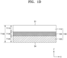
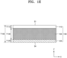
- FIGs. 1A to 1E are each a schematic view illustrating a dry cathode film 100 according to one or more embodiments of the present disclosure.
- an x direction may be a longitudinal direction of the dry cathode film 100
- a z direction may be a thickness direction of the dry cathode film 100.
- the dry cathode film 100 may include a first dry cathode active material layer 110 adjacent to a cathode current collector, and a second dry cathode active material layer 120 disposed on the first dry cathode active material layer 110.
- the first dry cathode active material layer 110 and the second dry cathode active material layer 120 may each independently include a dry cathode active material (e.g., in a form of particles), a dry sulfide-based solid electrolyte (e.g., in a form of particles), and a dry binder.
- the dry cathode active material may include a composite of Li 2 S, a lithium salt, and a carbon-based material.
- a content (e.g., amount or weight ratio) of the dry cathode active material in the first dry cathode active material layer 110 may be greater than a content (e.g., amount or weight ratio) of the dry cathode active material in the second dry cathode active material layer 120.
- a content (e.g., amount or weight ratio) of the dry sulfide-based solid electrolyte in the first dry cathode active material layer 110 may be less than a content (e.g., amount or weight ratio) of the dry sulfide-based solid electrolyte in the second dry cathode active material layer 120.
- a content (e.g., amount or weight ratio) of the dry binder in the first dry cathode active material layer 110 may be, for example, equal to a content (e.g., amount or weight ratio) of the dry binder in the second dry cathode active material layer 120.
- the equal content (e.g., amount or weight ratio) may refer to the dry cathode film 100 that is intentionally prepared to have substantially the equal content (e.g., amount or weight ratio).
- the equal content refers to that, in the first dry cathode active material layer 110 and the second cathode active material layer 120, an unintended relative content (e.g., amount or weight ratio) difference between components, for example, the dry binders, may be, for example, 2 or less, 1 or less, 0.5 or less, or 0.1 % or less.
- the content (e.g., amount or weight ratio) of the dry binder in the first dry cathode active material layer 110 may be greater than the content (e.g., amount or weight ratio) of the dry binder in the second dry cathode active material layer 120.
- a ratio of the content (e.g., amount or weight ratio) of the dry binder in the first dry cathode active material layer 110 to the content (e.g., amount or weight ratio) of the dry binder in the second dry cathode active material layer 120 may be, for example, in a range of about 3:1 to about 1.1:1, about 2:1 to about 1.1:1, or about 1.5:1 to about 1.1:1.
- the first dry cathode active material layer 110 having a high dry cathode active material content may have an increased dry binder content (e.g., amount or weight ratio) as compared with the second dry cathode active material layer 120 having a low dry cathode active material content (e.g., amount or weight ratio), and thus a change in volume of the dry cathode active material in the first dry cathode active material layer 110 may be more effectively suppressed or reduced.
- the cycle characteristics of an all-solid secondary battery including the dry cathode film 100 may be further improved.
- a first dry cathode active material layer thickness T110 may be, for example, equal to a second cathode active material layer thickness T120.
- the equal thickness may refer to the dry cathode film 100 that is intentionally prepared to have substantially the equal thickness.
- the equal thickness refers to that an unintended relative thickness difference between the thickness of the first dry cathode active material layer T110 and the thickness of the second cathode active material layer T120 may be, for example, 2 % or less, 1 % or less, 0.5 % or less, or 0.1 % or less.
- the first dry cathode active material layer thickness T110 may be, for example, different from the second cathode active material layer thickness T120.
- the first dry cathode active material layer thickness T110 may be, for example, less than the second cathode active material layer thickness T120.
- a ratio of the first dry cathode active material layer thickness T110 to the second cathode active material layer thickness T120 may be, for example, in a range of about 1:9 to about 1:1.1, about 1:5 about to 1:1.1, about 1:3 to about 1:1.1, or about 1:2 to about 1:1.1.
- the ratio of the first dry cathode active material layer thickness T110 to the second cathode active material layer thickness T120 may be in such a range (e.g., the ranges described above), ion conduction between the dry cathode film 100 and the electrolyte layer may be more easily performed.
- the cycle characteristics of an all-solid secondary battery including the dry cathode film 100 may be further improved.
- the high-rate characteristics of an all-solid secondary battery may be further improved.
- the first dry cathode active material layer thickness T110 may be, for example, greater than the second cathode active material layer thickness T120.
- the ratio of the thickness T110 of the first dry cathode active material layer thickness T110 to the second cathode active material layer thickness T120 may be, for example, in a range of about 9:1 to about 1.1:1, about 5:1 to about 1.1:1, about 3:1 to about 1.1:1, or about 2:1 to about 1.1:1.
- the ratio of the first dry cathode active material layer thickness T110 to the second cathode active material layer thickness T120 may be in such a range (e.g., the ranges described above), the energy density of the dry cathode film 100 may be further improved. In some embodiments, the energy density of an all-solid secondary battery including the dry cathode film 100 may be further improved.
- the ratio of the first dry cathode active material layer thickness T110 to the second cathode active material layer thickness T120 may be, for example, in a range of about 9:1 to about 1: 9, about 7:1 to about 1:7, about 5:1 to about 1:5, about 3:1 to about 1:3, or about 2:1 to about 1:2.
- the ratio of the first dry cathode active material layer thickness T110 to the second cathode active material layer thickness T120 may be in such a range (e.g., the ranges described above), the energy density and cycle characteristics of an all-solid secondary battery may be easily adjusted.
- the cycle characteristics of the all-solid secondary battery may relatively deteriorate, and if (e.g., when) the second cathode active material layer thickness T120 excessively increases, the energy density of the all-solid secondary battery may relatively decrease.
- a dry cathode film thickness T100 may be the sum of the first dry cathode active material layer thickness T110 and the second cathode active material layer thickness T120.
- the first dry cathode active material layer 110 may have, for example, a first surface S1 adjacent to the cathode current collector and a second surface S2 opposite to the first surface S1.
- the content (e.g., amount or weight ratio) of the dry cathode active material in a first region adjacent to the first surface S1 may be greater than the content (e.g., amount or weight ratio) of the dry cathode active material in a second region adjacent to the second surface S2.
- a ratio of the content (e.g., amount or weight ratio) of the dry cathode active material in the first region adjacent to the first surface S1 to the content (e.g., amount or weight ratio) of the dry cathode active material in the second region adjacent to the second surface S2 may be, for example, in a range of about 3:1 to about 1.1:1, about 2:1 to about 1.1:1, or about 1.5:1 to about 1.1:1.
- the first dry cathode active material layer 110 may have such a content (e.g., amount or weight ratio) distribution of the dry cathode active material, and thus the cycle characteristics of an all-solid secondary battery including the dry cathode film 100 may be further improved.
- the second dry cathode active material layer 120 may have, for example, a third surface S3 adjacent to the first dry cathode active material layer 110 and a fourth surface S4 opposite to the third surface S3.
- the content (e.g., amount or weight ratio) of the dry cathode active material in a third region adjacent to the third surface S3 may be greater than the content (e.g., amount or weight ratio) of the dry cathode active material in a fourth region adjacent to the fourth surface S4.
- a ratio of the content (e.g., amount or weight ratio) of the dry cathode active material in the third region adjacent to the third surface S3 to the content (e.g., amount or weight ratio) of the dry cathode active material in the fourth region adjacent to the fourth surface S4 may be, for example, in a range of about 3:1 to about 1.1:1, about 2:1 to about 1.1:1, or about 1.5:1 to about 1.1:1.
- the second dry cathode active material layer 120 may have such a content (e.g., amount or weight ratio) distribution of the dry cathode active material, and thus the cycle characteristics of an all-solid secondary battery including the dry cathode film 100 may be further improved.
- the first dry cathode active material layer 110 may have, for example, the first surface S1 adjacent to the cathode current collector and the second surface S2 opposite to the first surface S1.
- the content (e.g., amount or weight ratio) of the dry sulfide-based solid electrolyte in the first region adjacent to the first surface S1 may be less than the content (e.g., amount or weight ratio) of the dry sulfide-based solid electrolyte in the second region adjacent to the second surface S2.
- a ratio of the content (e.g., amount or weight ratio) of the dry sulfide-based solid electrolyte in the first region adjacent to the first surface S1 to the content (e.g., amount or weight ratio) of the dry sulfide-based solid electrolyte in the second region adjacent to the second surface S2 may be, for example, about 0.3:1 to about 0.9:1, about 0.5:1 to about 0.9:1, or about 0.7:1 to about 0.9:1.
- the first dry cathode active material layer 110 may have such a concentration distribution of the dry sulfide-based solid electrolyte, and thus the cycle characteristics of an all-solid secondary battery including the dry cathode film 100 may be further improved.
- the second dry cathode active material layer 120 may have, for example, the third surface S3 adjacent to the first dry cathode active material layer 110 and the fourth surface S4 opposite to the third surface S3.
- the content (e.g., amount or weight ratio) of the dry sulfide-based solid electrolyte in the third region adjacent to the third first surface S3 may be less than the content (e.g., amount or weight ratio) of the dry sulfide-based solid electrolyte in the fourth region adjacent to the fourth surface S4.
- a ratio of the content (e.g., amount or weight ratio) of the dry sulfide-based solid electrolyte in the third region adjacent to the third surface S3 to the content (e.g., amount or weight ratio) of the dry sulfide-based solid electrolyte in the fourth region adjacent to the fourth surface S4 may be, for example, in a range of about 0.3:1 to about 0.9:1, about 0.5:1 to about 0.9:1, or about 0.7:1 to about 0.9:1.
- the second dry cathode active material layer 120 may have such a concentration distribution of the dry sulfide-based solid electrolyte, and thus the cycle characteristics of an all-solid secondary battery including the dry cathode film 100 may be further improved.
- the first dry cathode active material layer 110 may have, for example, the first surface S1 adjacent to the cathode current collector and the second surface S2 opposite to the first surface S1.
- the content (e.g., amount or weight ratio) of the dry binder in the first region adjacent to the first surface S1 may be less than the content (e.g., amount or weight ratio) of the dry binder in the second region adjacent to the second surface S2.
- a ratio of the content (e.g., amount or weight ratio) of the dry binder in the first region adjacent to the first surface S1 to the content (e.g., amount or weight ratio) of the dry binder in the second region adjacent to the second surface S2 may be, for example, in a range of about 0.3:1 to about 0.9:1, about 0.5:1 to about 0.9:1, or about 0.7:1 to about 0.9:1.
- the first dry cathode active material layer 110 may have such a content (e.g., amount or weight ratio) distribution of the dry binder, and thus the cycle characteristics of an all-solid secondary battery including the dry cathode film 100 may be further improved.
- the second dry cathode active material layer 120 may have, for example, the third surface S3 adjacent to the first dry cathode active material layer 110 and the fourth surface S4 opposite to the third surface S3.
- the content (e.g., amount or weight ratio) of the dry binder in the third region adjacent to the third surface S3 may be less than the content (e.g., amount or weight ratio) of the dry binder in the fourth region adjacent to the fourth surface S4.
- a ratio of the content (e.g., amount or weight ratio) of the dry binder in the third region adjacent to the third surface S3 to the content (e.g., amount or weight ratio) of the dry binder in the fourth region adjacent to the fourth surface S4 may be, for example, in a range of about 0.3:1 to about 0.9:1, about 0.5:1 to about 0.9:1, or about 0.7:1 to about 0.9:1.
- the second dry cathode active material layer 120 may have such a content (e.g., amount or weight ratio) distribution of the dry binder, and thus the cycle characteristics of an all-solid secondary battery including the dry cathode film 100 may be further improved.
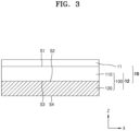
- the dry cathode film 100 may include one or more third dry cathode active material layers 130 between the first dry cathode active material layer 110 and the second dry cathode active material layer 120.
- the content (e.g., amount or weight ratio) of the dry cathode active material in the third dry cathode active material layer 130 may be less than the content (e.g., amount or weight ratio) of the dry cathode active material in the first dry cathode active material layer 110 and greater than the content (e.g., amount or weight ratio) of the dry cathode active material in the second dry cathode active material layer 120.
- the content (e.g., amount or weight ratio) of the dry sulfide-based solid electrolyte in the third dry cathode active material layer 130 may be greater than the content (e.g., amount or weight ratio) of the dry sulfide-based solid electrolyte in the first dry cathode active material layer 110 and less than the content (e.g., amount or weight ratio) of the dry sulfide-based solid electrolyte in the second dry cathode active material layer 120.
- the content (e.g., amount or weight ratio) of the dry binder in the third dry cathode active material layer 130 may be less than or equal to the content (e.g., amount or weight ratio) of the dry binder in the first dry cathode active material layer 110 and greater than or equal to the content (e.g., amount or weight ratio) of the dry binder in the second dry cathode active material layer 120.
- the dry cathode film 100 may include the third dry cathode active material layer 130, and thus a rapid change in composition of the dry cathode active material at an interface between the first dry cathode active material layer 110 and the second dry cathode active material layer 120 may be alleviated. In some embodiments, local side reactions due to non-substantially uniform electrode reactions occurring at the interface between the first dry cathode active material layer 110 and the second dry cathode active material layer 120 may be more effectively suppressed or reduced.
- a third cathode active material layer thickness T130 may be less than, for example, the first dry cathode active material layer thickness T110 or the second cathode active material layer thickness T120.
- a ratio of the third cathode active material layer thickness T130 to the first dry cathode active material layer thickness T110 or the second cathode active material layer thickness T120 may be, for example, in a range of about 1:9 to about 1:1.1, about 1:5 to about 1:1.1, about 1:3 to about 1:1.1, or about 1:2 to 1:1.1.
- the ratio of the third cathode active material layer thickness T130 to the first dry cathode active material layer thickness T110 or the second cathode active material layer thickness T120 may be in such a range (e.g., the ranges described above), the uniformity of an electrode reaction may be improved in the entirety of the dry cathode film 100. In some embodiments, local side reactions may be further suppressed or reduced during charging/discharging of an all-solid secondary battery.
- the third cathode active material layer thickness T130 may be greater than, for example, the first dry cathode active material layer thickness T110 or the second cathode active material layer thickness T120.
- the ratio of the third cathode active material layer thickness T130 to the first dry cathode active material layer thickness T110 or the second cathode active material layer thickness T120 may be, for example, in a range of about 9:1 to about 1.1:1, about 5:1 to about 1.1:1, about 3:1 to about 1.1:1, or about 2:1 to about 1.1:1.
- the ratio of the third cathode active material layer thickness T130 to the first dry cathode active material layer thickness T110 or the second cathode active material layer thickness T120 may be in such a range (e.g., the ranges described above), a rapid change in composition between the dry cathode film 100 and the cathode current collector or between the dry cathode film 100 and the electrolyte layer may be alleviated, thereby improving the uniformity of an electrode reaction. In some embodiments, local side reactions may be further suppressed or reduced during charging/discharging of an all-solid secondary battery.
- the third cathode active material layer thickness T130 may be substantially equal to, for example, the first dry cathode active material layer thickness T110 and/or the second cathode active material layer thickness T120.
- the ratio of the third cathode active material layer thickness T130 to the first dry cathode active material layer thickness T110 or the second cathode active material layer thickness T120 may be, for example, in a range of about 9:1 to about 1:9, about 7:1 to about 1:7, about 5:1 to about 1:5, about 3:1 to about 1:3, or about 2:1 to 1:2.
- the ratio of the third cathode active material layer thickness T130 to the first dry cathode active material layer thickness T110 or the second cathode active material layer thickness T120 may be in such a range (e.g., the ranges described above), the energy density and cycle characteristics of an all-solid secondary battery may be easily adjusted.
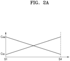
- FIGs. 2A to 2C are each a graph showing concentration gradients of components according to a depth in a thickness direction of the dry cathode film 100 according to one or more embodiments of the present disclosure.
- the dry cathode film 100 may have, for example, a gradient of a dry cathode active material concentration C AM in the thickness direction of the dry cathode film 100.
- the dry cathode active material concentration C AM may continuously decrease in the thickness direction of the dry cathode film 100 from the first surface S1 adjacent to the cathode current collector.
- the dry cathode active material concentration C AM may discontinuously, for example, stepwise, decrease in the thickness direction of the dry cathode film 100 from the first surface S1 adjacent to the cathode current collector.
- the dry cathode film 100 may have such a gradient of the dry cathode active material concentration C AM , the cycle characteristics of an all-solid secondary battery including the dry cathode film 100 may be further improved.
- the dry cathode film 100 may have, for example, a gradient of a dry sulfide-based solid electrolyte concentration C SE in the thickness direction of the dry cathode film 100.
- the dry sulfide-based solid electrolyte concentration C SE may continuously increase in the thickness direction of the dry cathode film 100 from the first surface S1 adjacent to the cathode current collector.
- the dry sulfide-based solid electrolyte concentration C SE may discontinuously, for example, stepwise, increase in the thickness direction of the dry cathode film 100 from the first surface S1 adjacent to the cathode current collector.
- the dry cathode film 100 may have such a gradient of the dry sulfide-based solid electrolyte concentration C SE , the cycle characteristics of an all-solid secondary battery including the dry cathode film 100 may be further improved.
- the dry cathode film 100 may have, for example, a gradient of a dry binder concentration in the thickness direction of the dry cathode film 100.
- the dry binder concentration may continuously increase in the thickness direction of the dry cathode film 100 from the first surface S1 adjacent to the cathode current collector.
- the dry binder concentration may increase discontinuously, for example, stepwise, in the thickness direction of the dry cathode film 100 from the first surface S1 adjacent to the cathode current collector.
- the dry cathode film 100 may have such a gradient of the dry binder concentration, the cycle characteristics of an all-solid secondary battery including the dry cathode film 100 may be further improved.
- Dry cathode film Composite of Li 2 S, lithium salt, and carbon-based material
- the dry cathode film 100 may include the first dry cathode active material layer 110 and the second dry cathode active material layer 120.
- the first dry cathode active material layer 110 and the second dry cathode active material layer 120 may each independently include a dry cathode active material, a dry sulfide-based solid electrolyte, and a dry binder.
- the dry cathode active material may include a composite of Li 2 S, a lithium salt, and a carbon-based material.
- the composite of Li 2 S, the lithium salt, and the carbon-based material may be represented by, for example, Li 2 S-Li a X b -C, wherein 1 ⁇ a ⁇ 5 and 1 ⁇ b ⁇ 5.
- X may be iodine (I), bromine (Br), chlorine (Cl), fluorine (F), hydrogen (H), oxygen (O), selenium (Se), tellurium (Te), nitrogen (N), phosphorus (P), arsenic (As), antimony (Sb), aluminum (Al), boron (B), OCl, PF 6 , BF 4 , SbF 6 , AsF 6 , ClO 4 , AlO 2 , AlCl 4 , NO 3 , CO 3 , BH 4 , SO 4 , BO 3 , PO 4 , NCl, NCl 2 , BN 2 , or any combination thereof.
- a may be, for example, 1, 2, 3, 4, or 5.
- b may be, for example, 1, 2,
- a size of a Li 2 S crystallite obtained from an X-ray diffraction (XRD) spectrum of the composite of Li 2 S, the lithium salt, and the carbon-based material may be, for example, 20 nm or less, 15 nm or less, or 10 nm or less. In some embodiments, the size of the Li 2 S crystallite obtained from the XRD spectrum of the composite of Li 2 S, the lithium salt, and the carbon-based material may be, for example, in a range of about 1 nm to about 20 nm, about 1 nm to about 15 nm, or about 3 nm to about 10 nm.
- the composite of Li 2 S, the lithium salt, and the carbon-based material may include the Li 2 S crystallite, and the size of the Li 2 S crystallite may be (e.g., decrease to) 20 nm or less, and thus a change in volume of the Li 2 S crystallite during charging/discharging may be alleviated.
- the size of the Li 2 S crystallite decreases, a change in volume due to one (e.g., single) Li 2 S crystallite may decrease, and thus the overall change in volume of the composite of Li 2 S, the lithium salt, and the carbon-based material may be alleviated during charging/discharging.
- the dry cathode film 100 may include the composite of Li 2 S, the lithium salt, and the carbon-based material, and thus the cycle characteristics of an all-solid secondary battery including the dry cathode film 100 may be improved.
- the size of the Li 2 S crystallite may decrease to 20 nm, and thus contact areas between Li 2 S, the lithium salt, and/or the carbon-based material may further increase. Because the contact areas between Li 2 S, the lithium salt, and/or the carbon-based material may further increase, the reversibility of an electrode reaction in an all-solid secondary battery including the composite of Li 2 S, the lithium salt, and the carbon-based material may be improved.
- the composite of Li 2 S, the lithium salt, and the carbon-based material may include, for example, a solid solution of Li 2 S and the lithium salt.
- the composite of Li 2 S, the lithium salt, and the carbon-based material may include the solid solution of Li 2 S and the lithium salt, the ionic conductivity of the composite of Li 2 S, the lithium salt, and the carbon-based material may further increase.
- the solid solution of Li 2 S and the lithium salt may include lithium atoms disposed in the Li 2 S crystallites, and thus the ionic conductivity of the solid solution of Li 2 S and the lithium salt may be improved as compared with that of Li 2 S.
- the ionic conductivity of the composite of Li 2 S, the lithium salt, and the carbon-based material may be improved, and the internal resistance of the composite of Li 2 S, the lithium salt, and the carbon-based material may be reduced.
- the dry cathode film 100 may include such a composite, the internal resistance of the dry cathode film 100 may be further reduced.
- the cycle characteristics of an all-solid secondary battery including the dry cathode film 100 may be further improved.
- the composite of Li 2 S, the lithium salt, and the carbon-based material may be distinguished from a simple mixture of Li 2 S, an alkali metal salt, and a carbon-based material.
- the simple mixture of Li 2 S, the alkali metal salt, and the carbon-based material may provide high interfacial resistance because a dense interface between Li 2 S, the alkali metal salt, and the carbon-based material may not be maintained, and thus the lifespan characteristics of an all-solid secondary battery may deteriorate.
- the composite of Li 2 S, the lithium salt, and the carbon-based material may include Li 2 S.
- the Li 2 S may have a high theoretical capacity, and thus an all-solid secondary battery having a high energy density may be provided.
- Li 2 S may form a composite with a lithium salt and a carbon-based material.
- a content (e.g., amount or weight ratio) of Li 2 S in the composite of Li 2 S, the lithium salt, and the carbon-based material may be, for example, in a range of about 50 wt% to about 80 wt%, about 50 wt% to about 75 wt%, or about 50 wt% to about 70 wt% of the total weight of the composite of Li 2 S, the lithium salt, and the carbon-based material. If (e.g., when) the content (e.g., amount or weight ratio) of Li 2 S excessively increases, it may not be easy to improve the ionic conductivity and/or electronic conductivity of Li 2 S. If (e.g., when) the content (e.g., amount or weight ratio) of Li 2 S is excessively low, the energy density of an all-solid secondary battery may decrease.
- the composite of Li 2 S, the lithium salt, and the carbon-based material may include the lithium salt.
- the lithium salt may be a compound that do not include, for example, sulfur (S).
- the lithium salt may be, for example, a binary compound or a ternary compound.
- the lithium salt may be a binary compound including lithium and one type or kind of element selected from Groups 13 to 17 of the periodic table of elements.
- the lithium salt may be a ternary compound including lithium and two types (kinds) of elements selected from Groups 13 to 17 of the periodic table of elements.
- the binary compound may include, for example, Lil, LiBr, LiCl, LiF, LiH, Li 2 O, Li 2 Se, Li 2 Te, LisN, LisP, Li 3 As, LisSb, Li 3 Al 2 , LiBs, or a combination thereof.
- the composite may include the binary compound, and thus the ionic conductivity of the composite may be further improved.
- the dry cathode film 100 may include such a composite, for example, a dry cathode active material, and thus the internal resistance of the dry cathode film 100 may be further reduced. In one or more embodiments, the cycle characteristics of an all-solid secondary battery including the dry cathode film 100 may be further improved.
- the ternary compound may include, for example, Li 3 OCl, LiPF 6 , LiBF 4 , LiSbF 6 , LiAsF 6 , LiClO 4 , LiAlO 2 , LiAlCl 4 , LiNOs, Li 2 CO 3 , LiBH 4 , Li 2 SO 4 , LisBOs, Li 3 PO 4 , Li 4 NCl, Li 5 NCl 2 , Li 3 BN 2 , or a combination thereof.
- the composite may include the ternary compound, and thus the ionic conductivity of the composite may be further improved.
- the dry cathode film 100 may include such a composite, for example, a dry cathode active material, and thus the internal resistance of the dry cathode film 100 may be further reduced. In one or more embodiments, the cycle characteristics of an all-solid secondary battery including the dry cathode film 100 may be further improved.
- a content (e.g., amount or weight ratio) of the lithium salt in the composite of Li 2 S, the lithium salt, and the carbon-based material may be, for example, in a range of about 1 wt% to about 40 wt%, about 5 wt% to about 35 wt%, about 10 wt% to about 35 wt%, about 15 wt% to about 35 wt%, about 20 wt% to about 35 wt%, or about 25 wt% to about 35 wt% of the total weight of the composite of Li 2 S, the lithium salt, and the carbon-based material.
- the energy density of an all-solid secondary battery may decrease. If (e.g., when) the content (e.g., amount or weight ratio) of the lithium salt excessively increases, the energy density of an all-solid secondary battery may decrease. If (e.g., when) the lithium salt is excessively low, the ionic conductivity of the composite of Li 2 S, the lithium salt, and the carbon-based material may decrease so that the internal resistance of the dry cathode film 100 may increase. In some embodiments, the cycle characteristics of an all-solid secondary battery including the dry cathode film 100 may deteriorate.
- a molar ratio of Li 2 S to the lithium salt is excessively high, an effect of improving ionic conductivity by the lithium salt may be insignificant. If (e.g., when) the molar ratio of Li 2 S to the lithium salt is excessively low, the energy density of a lithium battery including a composite cathode active material may decrease.
- the composite of Li 2 S, the lithium salt, and the carbon-based material may include the carbon-based material.
- the carbon-based material for example, any material, which is a material including carbon atoms and is utilized as a conductive material in the art, may be utilized.
- the carbon-based material may be, for example, crystalline carbon, amorphous carbon, or a combination thereof.
- the carbon-based material may be, for example, a sintered material of a carbon precursor.
- the carbon-based material may include, for example, carbon nanostructures.
- the carbon nanostructures may include, for example, one-dimensional carbon nanostructures, two-dimensional carbon nanostructures, three-dimensional carbon nanostructures, or a combination thereof.
- the carbon nanostructures may include, for example, carbon nanotubes (CNTs), carbon nanofibers (CNFs), carbon nanobelts, carbon nanorods, graphene, or a combination thereof.
- the carbon-based material may be, for example, a porous carbon-based material or a non-porous carbon-based material.
- the porous carbon-based materials may include, for example, periodic and regular two-dimensional or three-dimensional pores.
- the porous carbon-based material may include, for example, carbon black (CB) such as Ketjen black (KB), acetylene black (AB), Denka black, thermal black, or channel black; graphite; activated carbon; or a combination thereof.
- the form of the carbon-based material may be, for example, a particle form, a sheet form, a flake form, and/or the like, but embodiments of the present disclosure are not limited thereto. Any material utilized as carbon-based material in the art may be utilized.
- a content (e.g., amount or weight ratio) of the carbon-based material included in the composite of Li 2 S, the lithium salt, and the carbon-based material may be, for example, in a range of about 1 wt% to about 20 wt%, about 5 wt% to about 20 wt%, or about 10 wt% to about 20 wt% of the total weight of the composite.
- the energy density of the dry cathode film 100 and an all-solid secondary battery may decrease. If (e.g., when) the content (e.g., amount or weight ratio) of the carbon-based material excessively increases, the energy density of the dry cathode film 100 and an all-solid secondary battery may decrease. If (e.g., when) the content (e.g., amount or weight ratio) of the carbon-based material excessively decreases, the electronic (electron) conductivity of the composite of Li 2 S, the lithium salt, and the carbon-based material may decrease, and thus the internal resistance of the dry cathode film 100 may increase. In some embodiments, the cycle characteristics of all-solid secondary battery may deteriorate.
- a Mohs hardness of each of the lithium salt and the carbon-based material may be greater than that of Li 2 S.
- a Mohs hardness of Li 2 S may be, for example, 0.6 or less.
- the Mohs hardness of the lithium salt may be 0.7 or more, 0.8 or more, 0.9 or more, 1.0 or more, 1.5 or more, or 2.0 or more.
- the lithium salt may have a Mohs hardness in such a range (e.g., the ranges described above), Li 2 S may be more easily pulverized during a milling process, and a solid solution of Li 2 S and the lithium salt may be more easily formed.
- a Mohs hardness of LiI may be, for example, about 2.0.
- the Mohs hardness of the carbon-based material may be 0.7 or more, 0.8 or more, 0.9 or more, 1.0 or more, 1.2 or more, or 1.5 or more.
- the carbon-based material may have a Mohs hardness in such a range (e.g., the ranges described above), Li 2 S may be more easily pulverized during a milling process, and the composite of Li 2 S, the lithium salt, and the carbon-based material may be more easily formed.
- a Mohs hardness of CNFs may be, for example, about 1.5.
- the carbon-based material may include, for example, a fibrous carbon-based material.
- the composite of Li 2 S, the lithium salt, and the carbon-based material may include the fibrous carbon-based material, and thus the electronic conductivity of the composite of Li 2 S, the lithium salt, and the carbon-based material may be further improved.
- the composite of Li 2 S, the lithium salt, and the carbon-based material may include the fibrous carbon-based material, and thus electronic conduction may be more easily performed from the surface to the inside of the composite of Li 2 S, the lithium salt, and the carbon-based material.
- the internal resistance of the dry cathode film 100 including the composite of Li 2 S, the lithium salt, and the carbon-based material may be reduced, and the cycle characteristics of an all-solid secondary battery including the dry cathode film 100 may be further improved.
- an aspect ratio of the fibrous carbon-based material may be, for example, 2 or more, 3 or more, 4 or more, 5 or more, 10 or more, or 20 or more. In some embodiments, the aspect ratio of the fibrous carbon-based material may be, for example, in a range of about 2 to about 30, about 3 to about 30, about 4 to about 30, about 5 to about 30, about 10 to about 30, or about 20 to about 30. In some embodiments, the aspect ratio of the fibrous carbon-based material may be, for example, in a range of about 2 to about 30, about 2 to about 20, about 2 to about 10, about 2 to about 8, about 2 to about 5, or about 2 to about 4.
- the fibrous carbon-based material may have an aspect ratio in such a range (e.g., the ranges described above), the overall electronic conductivity of the composite of Li 2 S, the lithium salt, and the carbon-based material may be improved, and an imbalance of local electronic conductivity in the composite of Li 2 S, the lithium salt, and the carbon-based material may be further alleviated.
- the "aspect ratio" used herein may refer to the average aspect ratio and may be determined from SEM images or TEM images.
- the fibrous carbon-based material may include, for example, carbon nanostructures.
- the carbon nanostructures may include, for example, CNFs, CNTs, carbon nanobelts, carbon nanorods, or a combination thereof.
- a particle diameter or size of the dry cathode active material for example, a particle size of the composite of Li 2 S, the lithium salt, and the carbon-based material, may be, for example, 10 ⁇ m or less, 8 ⁇ m or less, 5 ⁇ m or less, 4 ⁇ m or less, 2 ⁇ m or less, 1.5 ⁇ m or less, or 1 ⁇ m or less.
- the particle size of the composite may be, for example, in a range of about 1 ⁇ m to about 10 ⁇ m, about 2 ⁇ m to about 10 ⁇ m, about 2 ⁇ m to about 8 ⁇ m, or about 3 ⁇ m to about 8 ⁇ m.
- the particle size of the composite of Li 2 S, the lithium salt, and the carbon-based material may be, for example, in a range of about 0.1 ⁇ m to about 10 ⁇ m, about 0.1 to about 8 ⁇ m, about 0.1 ⁇ m to about 5 ⁇ m, about 0.1 ⁇ m to about 4 ⁇ m, about 0.1 ⁇ m to about 2 ⁇ m, about 0.1 ⁇ m to about 1.5 ⁇ m, or about 0.1 ⁇ m to about 1 ⁇ m.
- the particle size of the composite of Li 2 S, the lithium salt, and the carbon-based material may have a size in such a range (e.g., the ranges described above), a change in volume during charging or discharging may be suppressed or reduced, thereby suppressing the deterioration of the dry cathode active material during charging/discharging. If (e.g., when) the particle size of the composite of Li 2 S, the lithium salt, and the carbon-based material excessively increases, a change in volume of the composite of Li 2 S, the lithium salt, and the carbon-based material may increase during charging/discharging, which may accelerate the deterioration of the dry cathode active material.
- the cycle characteristics of an all-solid secondary battery including such a dry cathode active material may deteriorate.
- the cycle characteristics of an all-solid secondary battery including the dry cathode active material of the present disclosure for example, the lifespan characteristics thereof, may be improved.
- the particle size of the composite of Li 2 S, the lithium salt, and the carbon-based material may be measured by utilizing, for example, laser diffraction, scanning electron microscopy, and/or the like.
- the size of the composite of Li 2 S, the lithium salt, and the carbon-based material may be an arithmetic average of particle diameters of a plurality of particles measured, for example, from a scanning electron microscope image by utilizing software.
- a particle diameter or size of Li 2 S included in the composite may be, for example, 2 ⁇ m or less, 1.5 ⁇ m or less, or 1 ⁇ m or less.
- the size of the Li 2 S particles may be, for example, in a range of about 0.1 ⁇ m to about 2 ⁇ m, about 0.1 ⁇ m to about 1.5 ⁇ m, or about 0.1 ⁇ m to about 1 ⁇ m.
- the Li 2 S particles may have a size in such a range (e.g., the ranges described above), a change in volume during charging/discharging may be suppressed or reduced, thereby suppressing the deterioration of the dry cathode active material including the composite during charging/discharging. If (e.g., when) the size of the Li 2 S particles excessively increases, a change in volume of the composite during charging/discharging may increase, which may accelerate the deterioration of the dry cathode active material including the composite. In some embodiments, the cycle characteristics of a secondary battery including the dry cathode active material may deteriorate.
- Li 2 S may be included in a range of about 10 parts by weight to about 80 parts by weight
- the lithium salt may be included in a range of about 1 part by weight to about 40 parts by weight
- the carbon-based material may be included in a range of about 1 part by weight to about 20 parts by weight.
- the content (e.g., amount or weight ratio) of Li 2 S included in the composite of Li 2 S, the lithium salt, and the carbon-based material may be, for example, in a range of about 10 parts by weight to about 80 parts by weight, about 20 parts by weight to about 70 parts by weight, about 30 parts by weight to about 60 parts by weight, or about 40 parts by weight to about 60 parts by weight with respect to about 100 parts by weight of the composite.
- the content (e.g., amount or weight ratio) of the lithium salt included in the composite of Li 2 S, the lithium salt, and the carbon-based material may be, for example, in a range of about 10 parts by weight to about 40 parts by weight, about 15 parts by weight to about 40 parts by weight, about 20 parts by weight to about 40 parts by weight, or about 25 parts by weight to about 35 parts by weight with respect to about 100 parts by weight of the composite.
- the content (e.g., amount or weight ratio) of the carbon-based material included in the composite of Li 2 S, the lithium salt, and the carbon-based material may be, for example, in a range of about 1 part by weight to about 20 parts by weight, about 5 parts by weight to about 20 parts by weight, or about 5 parts by weight to about 15 parts by weight with respect to about 100 parts by weight of the composite.
- Li 2 S, the lithium salt, and the carbon-based material may have a composition in such a range (e.g., the ranges described above), the dry cathode film 100 including the composite of Li 2 S, the lithium salt, and the carbon-based material may provide excellent or suitable ionic conductivity and/or electronic conductivity.
- the composite of Li 2 S, the lithium salt, and the carbon-based material may have an ionic (ion) conductivity of, for example, 1 ⁇ 10 -5 S/cm or more, 2 ⁇ 10 -5 S/cm or more, 4 ⁇ 10 -5 S/cm or more, 6 ⁇ 10 -5 S/cm or more, about 8 ⁇ 10 -5 S/cm or more, or 1 ⁇ 10 -4 S/cm or more at a temperature of about 25 °C.
- Ionic conductivity may be measured by utilizing, for example, electrochemical impedance spectroscopy, a direct current (DC) polarization method, and/or the like.
- the composite of Li 2 S, the lithium salt, and the carbon-based material may have ionic conductivity in such a range (e.g., the ranges described above), the internal resistance of the dry cathode film 100 including the composite of Li 2 S, the lithium salt, and the carbon-based material may be further reduced.
- the cycle characteristics of an all-solid secondary battery including the cathode film 100 may be improved.
- the composite of Li 2 S, the lithium salt, and the carbon-based material may have an electronic (electron) conductivity of, for example, 1 ⁇ 10 -5 S/cm or more, 2 ⁇ 10 -5 S/cm or more, 4 ⁇ 10 -5 S/cm or more, 6 ⁇ 10 -5 S/cm or more, about 8 ⁇ 10 -5 S/cm or more, or 1 ⁇ 10 -4 S/cm or more at a temperature of about 25 °C.
- Electronic conductivity may be measured by utilizing, for example, electrochemical impedance spectroscopy, a DC polarization method, and/or the like.
- the composite of Li 2 S, the lithium salt, and the carbon-based material may have electronic conductivity in such a range (e.g., the ranges described above), the internal resistance of the dry cathode film 100 including the composite of Li 2 S, the lithium salt, and the carbon-based material may be further reduced.
- the cycle characteristics of an all-solid secondary battery including the cathode film 100 may be improved.
- a content (e.g., amount or weight ratio) of the composite of the Li 2 S, the lithium salt, and the carbon-based material may be, for example, in a range of about 50 wt% to about 95 wt%, about 50 wt% to about 80 wt%, about 55 wt% to about 80 wt%, about 60 wt% to about 80 wt%, about 65 wt% to about 80 wt%, or about 70 wt% to about 80 wt% of the total weight of the dry cathode film 100.
- the content (e.g., amount or weight ratio) of the composite of Li 2 S, the lithium salt, and the carbon-based material excessively increases, a change in volume of a dry cathode may excessively increase during charging/discharging, which may deteriorate the cycle characteristics of an all-solid secondary battery. If (e.g., when) the content (e.g., amount or weight ratio) of the composite of Li 2 S, the lithium salt, and the carbon-based material excessively decreases, the energy density of an all-solid secondary battery may decrease.
- Dry cathode film Sulfide-based solid electrolyte
- the dry cathode film 100 may include the dry sulfide-based solid electrolyte.
- the sulfide-based solid electrolyte may include, for example, at least one selected from among: Li 2 S-P 2 S 5 ; Li 2 S-P 2 S 5 -LiX, wherein X is a halogen element; Li 2 S-P 2 S 5 -Li 2 O; Li 2 S-P 2 S 5 -Li 2 O-LiI; Li 2 S-SiS 2 ; Li 2 S-SiS 2 -LiI; Li 2 S-SiS 2 -LiBr; Li 2 S-SiS 2 -LiCl; Li 2 S-SiS 2 -B 2 S 3 -LiI; Li 2 S-SiS 2 -P 2 S 5 -LiI; Li 2 S-B 2 S 3 ; Li 2 S-P 2 S 5 -Z m S n , wherein m and n are each
- the dry sulfide-based solid electrolyte may be prepared by treating a starting material such as Li 2 S or P 2 S 5 through melt quenching or mechanical milling. In some embodiments, after such treating, heat treatment may be performed.
- the dry sulfide-based solid electrolyte may be in an amorphous state, a crystalline state, or a mixture state thereof.
- the dry sulfide-based solid electrolyte may include at least sulfur (S), phosphorus (P), and lithium (Li) as constituent elements, in some embodiments, the dry sulfide-based solid electrolyte may include, for example, Li 2 S-P 2 S 5 .
- a mixing molar ratio of Li 2 S to P 2 S 5 may be in a range of about 20:80 to about 90:10, about 25:75 to about 90:10, about 30:70 to about 70:30, or about 40:60 to about 60:40.
- the dry sulfide-based solid electrolyte may include (e.g., be), for example, an argyrodite-type or kind solid electrolyte represented by Formula 1: Formula 1 Li + 12-n-x A n+ X 2- 6-x Y - x
- A may be P, As, germanium (Ge), gallium (Ga), antimony (Sb), silicon (Si), tin (Sn), Al, indium (In), titanium (Ti), vanadium (V), niobium (Nb), or tantalum (Ta),
- X may be S, Se, or Te
- Y may be Cl, Br, I, F, CN, OCN, SCN, or N 3 , 1 ⁇ n ⁇ 5, and 0 ⁇ x ⁇ 2.
- the dry sulfide-based solid electrolyte may be, for example, an argyrodite-type or kind compound including at least one selected from among Li 7-x PS 6-x Cl x , wherein 0 ⁇ x ⁇ 2, Li 7-x PS 6-x Br x , wherein 0 ⁇ x ⁇ 2, and Li 7-x PS 6-x I x , wherein 0 ⁇ x ⁇ 2.
- the sulfide-based solid electrolyte may be, for example, an argyrodite-type or kind compound including at least one selected among from Li 6 PS 5 Cl, Li 6 PS 5 Br, and LisPSsl.
- the argyrodite-type or kind solid electrolyte may have a density of about 1.5 g/cc to about 2.0 g/cc.
- the argyrodite-type or kind solid electrolyte may have a density of 1.5 g/cc or more, which may reduce the internal resistance of an all-solid secondary battery and may more effectively suppress or reduce lithium dendrites from penetrating a solid electrolyte separator.
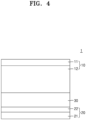
- the dry sulfide-based solid electrolyte included in the dry cathode film 100 may be the same as or different from a sulfide-based solid electrolyte included in an electrolyte layer 30 (e.g., referring to FIG. 4 ).
- a D50 average particle diameter of the dry sulfide-based solid electrolyte included in the dry cathode film 100 may be less than a D50 average particle diameter of the sulfide-based solid electrolyte included in the electrolyte layer 30.
- the D50 average particle diameter of the dry sulfide-based solid electrolyte included in the dry cathode film 100 may be 90 % or less, 80 % or less, 70 % or less, and 60 % or less, 50 % or less, 40 % or less, 30 % or less, or 20 % or less of the D50 average particle diameter of the sulfide-based solid electrolyte included in the electrolyte layer 30.
- the D50 average particle diameter may be, for example, a median particle diameter (D50).
- the median particle diameter (D50) may be a particle size corresponding to a 50 % cumulative volume when a particle size distribution measured through a laser diffraction method is calculated from particles having a smaller particle size to particles having a larger particle size.
- a content (e.g., amount or weight ratio) of the sulfide-based solid electrolyte included in the dry cathode film 100 may be in a range of about 5 wt% to about 45 wt%, about 15 wt% to about 40 wt%, about 20 wt% to about 40 wt%, or about 25 wt% to about 40 wt% of the total weight of the dry cathode film 100.
- the dry cathode film 100 may include the sulfide-based solid electrolyte in such a range and thus may provide reduced internal resistance and improved ionic conductivity.
- the internal resistance of the dry cathode film 100 may increase, which may deteriorate the cycle characteristics of an all-solid secondary battery. If (e.g., when) the content (e.g., amount or weight ratio) of sulfide-based solid electrolyte excessively increases, the energy density of an all-solid secondary battery may decrease.
- Dry cathode film Dry binder
- the dry cathode film 100 may include the dry binder.
- the dry binder may be, for example, a binder that is not impregnated, dissolved, or dispersed in a process solvent in a process of preparing the dry cathode film 100.
- the dry binder may be, for example, a binder that does not include a process solvent or is not in contact with a process solvent in a process of preparing the dry cathode film 100.
- the dry binder may be, for example, a fibrillized binder or a fibrous binder.
- the fibrillized binder or fibrous binder may serve as a porous matrix that supports and binds the dry cathode active material and other components included in the dry cathode film 100.
- the fibrillized binder or fibrous binder may be intermittently disposed on a surface of the dry cathode active material without aggregation to bind a plurality of dry cathode active materials, and thus an increase in internal resistance of the dry cathode film 100 due to the dry binder may be effectively suppressed or reduced. It may be confirmed that the fibrillized binder or fibrous binder has a fibrous form, for example, from a scanning electron microscope image of a dry cathode cross section.
- the fibrillized binder or fibrous binder may have an aspect ratio of, for example, 10 or more, 20 or more, 50 or more, or 100 or more.
- the dry binder may be fibrillized, for example, in a longitudinal direction (machine direction (MD)) of the dry cathode film 100.
- the dry binder may be fibrillized, for example, in a longitudinal direction of the first dry cathode active material layer 110.
- the dry binder may be fibrillized, for example, in a longitudinal direction of the second cathode active material layer 120.
- the dry binder may be fibrillized in substantially the same direction in the first dry cathode active material layer 110 and the second cathode active material layer 120.
- the dry binder may include, for example, polytetrafluoroethylene (PTFE), a polyvinylidene fluoride-hexafluoropropylene (PVDF-HFP) copolymer, polyvinylidene fluoride (PVDF), polyvinyl alcohol (PVA), polyacrylonitrile, carboxymethylcellulose (CMC), starch, hydroxypropylcellulose, cellulose, polyvinylpyrrolidone (PVP), polyethylene (PE), polypropylene (PP), ethylene-propylene-diene monomer (EPDM) rubber, a sulfonated-EPDM rubber, styrene butadiene rubber (SBR), fluoro rubber, or a copolymer thereof, but embodiments of the present disclosure are not necessarily limited thereto.
- PTFE polytetrafluoroethylene
- PVDF-HFP polyvinylidene fluoride-hexafluoropropylene
- PVDF polyvinylidene flu
- the dry binder may include, for example, a fluorine-based binder.
- the fluorine-based binder may include, for example, PTFE, a PVDF-HFP copolymer, and/or PVDF.
- a glass transition temperature (Tg) of the dry binder may be, for example, in a range of about -30 °C to about 150 °C, about 15 °C to about 150 °C, about 15 °C to about 130 °C, about 50 °C to about 130 °C, about 100 °C to about 130 °C, or about 120 °C to about 130 °C.
- the glass transition temperature Tg of the dry binder may be, for example, in a range of about - 30 °C to about 150 °C, about -30 °C to about 100 °C, about -30 °C to about 50 °C, about -30 °C to about 15 °C, about -30 °C to about -10 °C, or about 30 °C to about -20 ° C.
- a glass transition temperature of PTFE may be, for example, in a range of about 120 °C to about 130 °C.
- the dry binder may have a glass transition temperature in such a range (e.g., the ranges described above), the fibrillized binder or fibrous binder may be more easily obtained in a process of preparing a dry electrode.
- a content (e.g., amount or weight ratio) of the dry binder may be, for example, in a range of about 0.1 wt% to about 5 wt%, about 0.5 wt% to about 5 wt%, about 1 wt% to about 5 wt%, or about 1 wt% to about 3 wt% with respect to the total weight of the dry cathode film 100.
- the dry cathode film 100 may include the dry binder in such a range (e.g., the ranges described above) so that a binding force of the dry cathode film 100 may be improved, and the dry cathode film 100 may maintain an increased energy density.
- the dry cathode film 100 may further include, for example, a conductive material.
- the conductive material may be, for example, a dry conductive material.
- the dry conductive material may be, for example, a conductive material that is not impregnated, dissolved, or dispersed in a process solvent in a process of preparing the dry cathode film 100.
- the dry conductive material may be, for example, a conductive material that does not include a process solvent or is not in contact with a process solvent in a process of preparing the dry cathode film 100.
- the dry conductive material may include, for example, a carbon-based conductive material.
- the carbon-based conductive material may include, for example, a fibrous carbon-based material having an aspect ratio of 10 or more, a particulate carbon-based material having an aspect ratio of less than 10, or a combination thereof.
- the fibrous carbon-based material having an aspect ratio of 10 or more may include, for example, a carbon fiber, CNTs, carbon nanobelts, and/or the like, but embodiments of the present disclosure are not limited thereto. Any material utilized as a carbon-based conductive material in the art may be utilized. In some embodiments, the fibrous carbon-based material having an aspect ratio of 10 or more may be selected from second carbon-based materials. A fibrous carbon-based conductive material may be distinguished from a carbon-based material constituting a portion of the dry cathode active material in that the fibrous carbon-based conductive material is simply mixed with the dry cathode active material.
- the particulate carbon-based material having an aspect ratio of less than 10 may include, for example, CB, AB, KB, natural graphite, artificial graphite, and/or the like, but embodiments of the present disclosure are not limited thereto. Any material utilized as a carbon-based conductive material in the art may be utilized. In one or more embodiments, the aspect ratio of the particulate carbon-based material may be, for example, in a range of about 1 to about 7, about 1 to about 5, about 1 to about 3, or about 1 to about 2.
- a content (e.g., amount or weight ratio) of the dry conductive material included in the dry cathode film 100 may be, for example, in a range of about 0.1 wt% to about 5 wt%, about 0.5 wt% to about 5 wt%, or about 1 wt% to about 5 wt% with respect to the total weight of the dry cathode film 100.
- the dry cathode film 100 may further include the dry conductive material in such a range (e.g., the ranges described above) so that the electronic conductivity of the dry cathode film 100 may be further improved, and the cycle characteristics of an all-solid secondary battery including the dry cathode film 100 may be further improved.
- the dry conductive material may not be provided.
- the dry cathode film 100 may further include, for example, additives such as a filler, a coating agent, a dispersant, and an ion-conductive adjuvant.
- a coating agent As a filler, a coating agent, a dispersant, an ion-conductive adjuvant, and/or the like that may be included in the dry cathode film 100, suitable materials generally utilized in cathodes of all-solid secondary batteries may be utilized.
- Dry cathode film Physical properties
- the dry cathode film 100 may be, for example, a self-standing film.
- the dry cathode film 100 may maintain the form of a film, for example, without a support. Therefore, the dry cathode film 100 may be prepared as a separate self-standing film and then disposed on the cathode current collector.
- the dry cathode film 100 may be prepared in a dry type or kind and thus may not include (e.g., may exclude) an intentionally added process solvent.
- the dry cathode film 100 may not include (e.g., may exclude) a residual process solvent. An unintended trace amount of solvent may remain in the dry cathode film 100, but the solvent may not be an intentionally added process solvent.
- the dry cathode film 100 may be distinguished from a wet cathode film prepared by mixing constituent components and a process solvent and then drying the resultant mixture to remove a portion or the entirety of the process solvent.
- a thickness of the dry cathode film 100 may be, for example, in a range of about 50 ⁇ m to about 500 ⁇ m, about 50 ⁇ m to about 400 ⁇ m, about 50 ⁇ m to about 300 ⁇ m, or about 50 ⁇ m to about 250 ⁇ m. If (e.g., when) the dry cathode film 100 is excessively thin, the number of current collectors may increase, and thus the energy density per unit volume of an all-solid secondary battery may decrease. If (e.g., when) the thickness of the dry cathode film 100 excessively increases, the internal resistance of a dry cathode may increase, which may deteriorate the cycle characteristics of an all-solid secondary battery.
- the dry cathode film 100 may have, for example, a tensile strength of 500 kPa or more, 700 kPa or more, or 900 kPa or more at a temperature of about 25 °C. in some embodiments, the dry cathode film 100 may have, for example, a tensile strength of about 500 kPa to about 5,000 kPa, about 700 kPa to about 5,000 kPa, about 700 kPa to about 3,000 kPa, about 700 kPa to about 2,000 kPa, or about 900 kPa to about 2,000 kPa at a temperature of about 25 °C.
- the dry cathode film 100 may have a tensile strength in such a range (e.g., the ranges described above), the structural stability of the dry cathode film 100 may be improved. In one or more embodiments, the dry cathode film 100 may maintain a stable three-dimensional conductive network during a charging/discharging process so that the reversibility of an electrode reaction may be improved. The dry cathode film 100 may have a high tensile strength in such a range (e.g., ranges described above), the mechanical strength of the dry cathode film 100 may be improved.
- the dry cathode film 100 may have the improved mechanical strength, which may suppress or reduce the local deterioration due to a change in volume of a dry cathode including the dry cathode film 100 and an all-solid secondary battery including the same during charging/discharging.
- the cycle characteristics of an all-solid secondary battery may be improved. If (e.g., when) the tensile strength of the dry cathode film 100 is excessively low, defects such as cracks or disconnections may occur during a manufacturing process or a charging/discharging process of an all-solid secondary battery, thereby reducing the yield of the all-solid secondary battery.
- Tensile strength at break of the dry cathode film 100 may be measured, for example, according to ASTM D412.
- the dry cathode film 100 may have, for example, a surface resistivity of 70 ⁇ /sq or less, 60 ⁇ /sq or less, 50 ⁇ /sq or less, 40 ⁇ /sq or less, or 35 ⁇ /s or less at a temperature of about 25 °C and a pressure of about 1 atm.
- the dry cathode film 100 may have, for example, a surface resistivity of about 0.1 ⁇ /sq to about 70 ⁇ /sq, about 0.5 ⁇ /sq to about 60 ⁇ /sq, about 1 ⁇ /sq to about 50 ⁇ /sq, about 1 ⁇ /sq to about 40 ⁇ /sq or about 1 ⁇ /sq to about 35 ⁇ /sq at a temperature of about 25 °C and a pressure of about 1 atm.
- the dry cathode film 100 may have a reduced surface resistivity in such a range (e.g., the ranges described above), the surface resistance, interface resistance, and/or internal resistance of the dry cathode film 100 may be reduced.
- the cycle characteristics of an all-solid secondary battery including the dry cathode film 100 may be further improved.
- the surface resistivity of the dry cathode film 100 may be measured, for example, according to ASTM D257 or IEC 62631-3-1.
- a dry cathode may include a cathode current collector, and a cathode active material layer on at least one surface (e.g., one surface or two opposite surfaces) of the cathode current collector.
- the cathode active material layer may include the above-described dry cathode film.
- the dry cathode may include the above-described dry cathode film and thus may have a further reduced internal resistance.
- the cycle characteristics of a secondary battery including the dry cathode may be further improved.
- FIG. 3 is a schematic view of a dry cathode 10 according to one or more embodiments of the present disclosure.
- the dry cathode 10 may include a cathode current collector 11, and a cathode active material layer 12 disposed on one surface or two surfaces of the cathode current collector 11.
- the cathode active material layer 12 may include the above-described dry cathode film 100.
- the dry cathode film 100 may include a first dry cathode active material layer 110 adjacent to the cathode current collector 11 and a second dry cathode active material layer 120 disposed on the first dry cathode active material layer 110.
- the second dry cathode active material layer 120 may be disposed adjacent to an electrolyte layer.
- the cathode current collector 11 may be provided as a plate, foil, and/or the like, made of, for example, indium (In), copper (Cu), magnesium (Mg), stainless steel, titanium (Ti), iron (Fe), cobalt (Co), nickel (Ni), zinc (Zn), aluminum (Al), germanium (Ge), lithium (Li), or an alloy thereof. In some embodiments, the cathode current collector 11 may not be provided.
- a thickness of the cathode current collector 11 may be, for example, in a range of about 1 ⁇ m to about 100 ⁇ m, about 1 ⁇ m to about 50 ⁇ m, about 5 ⁇ m to about 25 ⁇ m, or about 10 ⁇ m to about 20 ⁇ m.
- a metal chip may be added between the metal layer and the lead tab.
- the metal chip may be a flake made of the same material as a metal of the metal layer.
- the metal chip may be, for example, metal foil or a metal mesh.
- the metal chip may be, for example, aluminum foil, copper foil, or SUS (stainless steel) foil. If (e.g., when) the metal chip is disposed on the metal layer and then welded to the lead tab, the lead tab may be welded to the metal chip/metal layer stack or a metal chip/metal layer/base film stack.
- a melting point of the base film may be, for example, in a range of about 100 °C to about 300 °C, about 100 °C to about 250 °C, or about 100 °C to about 200 °C.
- the base film may have a melting point in such a range (e.g., the ranges described above), the base film may be melted and easily coupled to the lead tab in a process of welding the lead tab.
- surface treatment such as corona treatment may be performed on the base film.
- the metal chip may have a thickness in such a range (e.g., the ranges described above), the metal layer and the lead tab may be more easily connected.
- the cathode current collector 11 may have such a structure, and thus the weight of a cathode may be reduced, thereby improving the energy density of the cathode and a lithium battery.
- the interlayer may be disposed, for example, on one surface or two surfaces (e.g., two opposite surfaces) of the cathode current collector 11.
- the interlayer may be disposed on one surface or two surfaces of the cathode current collector 11, and thus a binding force between the cathode current collector 11 and the dry cathode film 100 may be further improved.
- a thickness of the interlayer may be, for example, in a range of about 0.01 % to about 30 %, about 0.1 % to about 30 %, about 0.5 % to about 30 %, about 1 % to about 25 %, about 1 % to about 20 %, about 1 % to about 15 %, about 1 % to about 10 %, about 1 % to about 5 %, or about 1 % to about 3 % of the thickness of the cathode current collector 11.
- the thickness of the interlayer may be, for example, in a range of about 10 nm to about 5 ⁇ m, about 50 nm to about 5 ⁇ m, about 200 nm to about 4 ⁇ m, about 500 nm to about 3 ⁇ m, about 500 nm to about 2 ⁇ m, about 500 nm to about 1.5 ⁇ m, or about 700 nm to about 1.3 ⁇ m.
- the interlayer may have a thickness in such a range so that a binding force between the cathode current collector 11 and the dry cathode film 100 may be further improved, and an increase in interfacial resistance may be suppressed or reduced.
- the interlayer may include, for example, a carbon-based conductive material.
- the carbon-based conductive material included in the interlayer layer may be selected from carbon-based conductive materials utilized in a dry electrode film (e.g., dry cathode film).
- the interlayer may include a carbon-based conductive material that is identical to the carbon-based conductive material utilized in the dry electrode film (e.g., dry cathode film).
- the interlayer may include the carbon-based conductive material and thus may be, for example, a conductive layer.
- the dry cathode 10 may include the cathode current collector 11 and the cathode active material layer 12 on one surface of the cathode current collector 11.
- a first inactive member 40 may be disposed on one side surface of the dry cathode 10. Referring to FIGs. 7 and 9 , in some embodiments, the first inactive member 40 may be disposed on one side surface of each of the cathode active material layer 12 and the cathode current collector 11. Referring to FIGs.
- the first inactive member 40 may be disposed on one side surface of the cathode active material layer 12 and may be disposed between an electrolyte layer 30 and the cathode current collector 11 opposite to the electrolyte layer 30. In some embodiments, the first inactive member 40 may not be disposed on one side surface of the cathode current collector 11.
- the electrolyte layer 30 may be, for example, a solid electrolyte layer.
- the inactive member 40 may be included to prevent or reduce cracks of the electrolyte layer 30 during manufacturing and/or charging/discharging of an all-solid secondary battery 1, thereby improving the cycle characteristics of the all-solid solid secondary battery 1.
- ununiform pressure may be applied to the electrolyte layer 30 in contact with the dry cathode 10 during manufacturing and/or charging/discharging of the all-solid secondary battery 1 to cause cracks in the electrolyte layer 30, and a lithium metal may be grown through the cracks to increase a possibility of the occurrence of a short circuit.
- a thickness of the first inactive member 40 may be greater than or equal to a thickness of the cathode active material layer 12. In some embodiments, in the all-solid secondary battery 1, the thickness of the first inactive member 40 may be substantially equal to the thickness of the dry cathode 10. The thickness of the first inactive member 40 may be equal to the thickness of the dry cathode 10, and thus substantially uniform pressure may be applied between the dry cathode 10 and the electrolyte layer 30, and the dry cathode 10 and the electrolyte layer 30 may be in sufficiently close contact with each other, thereby reducing interfacial resistance between the dry cathode 10 and the electrolyte layer 30. In some embodiments, the electrolyte layer 30 may be sufficiently sintered during a process of pressing and manufacturing the all-solid secondary battery 1, thereby reducing the internal resistance of the electrolyte layer 30 and the all-solid secondary battery 1 including the same.
- the first inactive member 40 may surround a side surface of the dry cathode 10 and may be in contact with the electrolyte layer 30.
- the first inactive member 40 may surround the side surface of the dry cathode 10 and may be in contact with the electrolyte layer 30, thereby effectively suppressing cracks of the electrolyte layer 30, which may be caused in a portion of the electrolyte layer 30, which is not in contact with the dry cathode 10, by a pressure difference during a pressing process.
- the first inactive member 40 may surround the side surface of the dry cathode 10 and may be separated from an anode 20, for example, a first anode active material layer 22.
- the first inactive member 40 may surround the side surface of the dry cathode 10, may be in contact with the electrolyte layer 30, and may be separated from the anode 20. In some embodiments, a possibility of a short circuit occurring due to physical contact between the dry cathode 10 and the first anode active material layer 22 or a possibility of a short circuit occurring due to the overcharging of lithium may be suppressed or reduced.
- the first inactive member 40 may be disposed on one side surface of the cathode active material layer 12 and concurrently (e.g., simultaneously) may be disposed on one side surface of the cathode current collector 11, thereby more effectively suppressing a possibility of a short circuit occurring due to contact between the cathode current collector 11 and the anode 20.
- the first inactive member 40 may extend from one side surface of the dry cathode 10 to an end portion of the electrolyte layer 30.
- the first inactive member 40 may extend to the end portion of the electrolyte layer 30 so that cracks occurring at the end portion of the electrolyte layer 30 may be suppressed or reduced.
- the end portion of the electrolyte layer 30 may be the outermost portion in contact with a side surface of the electrolyte layer 30.
- the first inactive member 40 may extend to the outermost portion in contact with the side surface of the electrolyte layer 30.
- the first inactive member 40 may be separated from the anode 20, for example, the first anode active material layer 22.
- the first inactive member 40 may extend to the end portion of the electrolyte layer 30 but may not be in contact with the anode 20.
- the inactive member 40 may fill a space extending from one side surface of the dry cathode 10 to the end portion of the electrolyte layer 30.
- a width of the first inactive member 40 extending from one side surface of the dry cathode 10 to the end portion of the electrolyte layer 30 may be, for example, in a range of about 1 % to about 30 %, about 1 % to about 25 %, about 1 % to about 20 %, about 1 % to about 15 %, about 1 % to about 10 %, or about 1 % to about 5 % of a width between one side surface of the dry cathode 10 and the other side surface opposite to the one side surface. If (e.g., when) the width of the first inactive member 40 is excessively wide, the energy density of the all-solid secondary battery 1 may decrease. If (e.g., when) the width of the first inactive member 40 is excessively narrow, an effect of arranging the first inactive member 40 may be insignificant.
- an area of the dry cathode 10 may be smaller than an area of the electrolyte layer 30 in contact with the dry cathode 10.
- the first inactive member 40 may be disposed to surround the side surface of the dry cathode 10 to compensate for a difference in area between the dry cathode 10 and the electrolyte layer 30.
- the area of the first inactive member 40 may compensate for the difference between the area of the dry cathode 10 and the area of the electrolyte layer 30, thereby effectively preventing or reducing cracks of the electrolyte layer 30 caused by a pressure difference during a pressing process.
- the sum of the area of the dry cathode 10 and the area of the first inactive member 40 may be substantially equal to the area of the electrolyte layer 30.
- the electrolyte layer 30 may be, for example, a solid electrolyte layer.
- the area of the dry cathode 10 may be, for example, less than 100 %, 99 % or less, 98 % or less, 97 % or less, 96 % or less, or 95 % or less of the area of the electrolyte layer 30. In some embodiments, the area of the dry cathode 10 may be, for example, in a range of about 50 % to less than 100 %, about 50 % to about 99 %, about 55 % to about 98 %, about 60 % to about 97 %, about 70 % to about 96 %, about 80 % to about 95 %, or about 85 % to about 95 %.of the area of the electrolyte layer 30.
- the area of the dry cathode 10 may be, for example, equal to the area of the cathode active material layer 12. In some embodiments, the area of the dry cathode 10 may be, for example, equal to the area of the cathode current collector 11.
- the area of the first inactive member 40 may be, for example, 50 % or less, 40 % or less, 30 % or less, 20 % or less, or 10 % or less of the area of the dry cathode 10. In some embodiments, the area of the first inactive member 40 may be, for example, in a range of about 1 % to about 50 %, about 5 % to about 40 %, about 5 % to about 30 %, about 5 % to about 20 %, or about 5 % to about 15 % of the area of the dry cathode 10.
- the area of the dry cathode 10 may be smaller than the area of the anode current collector 21.
- the area of the dry cathode 10 may be, for example, less than 100 %, 99 % or less, 98 % or less, 97 % or less, 96 % or less, or 95 % or less of the area of the anode current collector 21.
- the area of the dry cathode 10 may be, for example, in a range of about 50 % to less than 100 %, about 50 % to about 99 %, about 55 % to about 98 %, about 60 % to about 97 %, about 70 % to about 96 %, about 80 % to about 95 %, or about 85 % to about 95 % of the area of the anode current collector 21.
- the area of the anode current collector 21 may be, for example, equal to the area of the anode 20.
- the area of the anode current collector 21 may be, for example, equal to the area of the first anode active material layer 22.
- "equal" area, length, width, thickness, and/or shape may include all cases of having “substantially equal” area, length, width, thickness, and/or shape, excluding a case in which areas, lengths, widths, thicknesses, and/or shapes are intentionally different from each other.
- "Equal" area, length, width, and/or thickness includes a range in which the unintended difference in area, length, width, and/or thickness between compared objects is, for example, less than 3 %, less than 2 %, less than 1 %, less than 0.5 %, or less than 0.1 %.
- the thickness of the first inactive member 40 may be, for example, greater than the thickness of the first anode active material layer 22.
- the thickness of the first anode active material layer 22 may be, for example, 50 % or less, 40 % or less, 30 % or less, 20 % or less, or 10 % or less of the thickness of the first inactive member 40.
- the thickness of the first anode active material layer 22 may be, for example, in a range of about 1 % to about 50 %, about 1 % to about 40 %, about 1 % to about 30 %, about 1 % to about 20 %, or about 1 % to about 10 % of the thickness of the first inactive member 40.
- the first inactive member 40 may be a gasket.
- the gasket By utilizing the gasket as the first inactive member 40, cracks of the electrolyte layer 30 caused by a pressure difference during a pressing process may be effectively suppressed or reduced.
- the first inactive member 40 may have, for example, a single-layer structure. In some embodiments, the first inactive member 40 may have a multi-layer structure. In the first inactive member 40 having the multi-layer structure, respective layers may have different compositions. The first inactive member 40 having the multi-layer structure may have, for example, a two-layer structure, a three-layer structure, a four-layer structure, or a five-layer structure. The first inactive member 40 having the multi-layer structure may include, for example, one or more adhesive layers and one or more support layers.
- the adhesive layer may effectively prevent or reduce separation between the dry cathode 10 and the electrolyte layer 30 due to a change in volume of the dry cathode 10 that occurs during a charging/discharging process of the all-solid secondary battery 1 and may provide a binding force between the support layer and other layers to improve the film strength of the first inactive member 40.
- the support layer may provide a supporting force to the first inactive member 40, may prevent or reduce the nonuniformity of pressure applied to the electrolyte layer 30 during a pressing process or a charging/discharging process, and may prevent or reduce the shape deformation of the all-solid secondary battery 1 to be manufactured.
- the first inactive member 40 may be, for example, a flame-retardant inactive member.
- the flame-retardant inactive member may provide flame retardancy to prevent or reduce a possibility of thermal runaway and ignition of the all-solid secondary battery 1.
- the safety of the all-solid secondary battery 1 may be further improved.
- the flame-retardant inactive member may be to absorb residual moisture in the all-solid secondary battery 1, thereby preventing or reducing the deterioration of the all-solid secondary battery 1 and improving the lifespan characteristics of the all-solid secondary battery 1.
- the flame-retardant inactive member may include, for example, a matrix and a filler.
- the matrix may include, for example, a substrate and a reinforcing material.
- the matrix may include, for example, a fibrous substrate and a fibrous reinforcing material.
- the matrix may include the substrate to have elasticity. In some embodiments, the matrix may effectively accommodate a change in volume of the all-solid secondary battery 1 during charging/discharging and may be disposed at any one of one or more suitable positions.
- the substrate included in the matrix may include, for example, a first fibrous material.
- the substrate may effectively accommodate a change in volume of the dry cathode 10 which occurs during a charging/discharging process of the all-solid secondary battery 1 and may effectively suppress or reduce the deformation of the first inactive member 40 due to the change in volume of the dry cathode 10.
- the first fibrous material may be, for example, a material having an aspect ratio of 5 or more, 20 or more, or 50 or more.
- the first fibrous material may be, for example, a material having an aspect ratio of about 5 to about 1,000, about 20 to about 1,000, or about 50 to about 1,000.
- the first fibrous material may be, for example, an insulating material.
- the first fibrous material may be the insulating material, and thus a short circuit between the dry cathode 10 and the anode 20, which occur due to lithium dendrites and/or the like during charging/discharging of the all-solid secondary battery 1, may be effectively prevented or reduced.
- the first fibrous material may include, for example, at least one selected from among a pulp fiber, an insulating polymer fiber, and an ion conductive polymer fiber.
- the matrix may include the reinforcing material, and thus the strength thereof may be improved. In some embodiments, the matrix may prevent or reduce an excessive change in volume of the all-solid secondary battery 1 during changing/discharging and prevent or reduce the deformation of the all-solid secondary battery 1.
- the reinforcing material included in the matrix may include, for example, a second fibrous material.
- the reinforcing material may include the second fibrous material, and thus the strength of the matrix may more uniformly increase.
- the second fibrous material may be, for example, a material having an aspect ratio of 3 or more, 5 or more, or 10 or more.
- the second fibrous material may be, for example, a material having an aspect ratio of about 3 to about 100, about 5 to about 100, or about 10 to about 100.
- the second fibrous material may be, for example, a flame-retardant material.
- the second fibrous material may be the flame-retardant material, and thus ignition due to thermal runaway occurring during a charging/discharging process of the all-solid secondary battery 1 or an external impact may be effectively suppressed or reduced.
- the second fibrous material may be, for example, a glass fiber, a metal oxide fiber, or a ceramic fiber.
- the flame-retardant inactive member may include a filler in addition to the matrix.
- the filler may be disposed in the matrix, on a surface of the matrix, or both (e.g., simultaneously) in the matrix and on the surface.
- the filler may include, for example, an inorganic material.
- the filler included in the flame-retardant inactive member may be, for example, a moisture getter.
- the filler may adsorb moisture at a temperature of less than 100 °C to remove moisture remaining in the all-solid secondary battery 1, thereby preventing or reducing the deterioration of the all-solid secondary battery 1.
- the filler may release the adsorbed moisture to effectively suppress or reduce ignition of the all-solid secondary battery 1.
- the filler may be, for example, a flame retardant.
- the filler may be, for example, a metal hydroxide having moisture adsorption properties.
- the metal hydroxide included in the filler may be, for example, Mg(OH) 2 , Fe(OH) 3 , Sb(OH) 3 , Sn(OH) 4 , TI(OH) 3 , Zr(OH) 4 , Al(OH) 3 , or a combination thereof.
- a content (e.g., amount or weight ratio) of the filler included in the flame-retardant inactive member may be, for example, in a range of about 10 parts by weight to about 80 parts by weight, about 20 parts by weight to about 80 parts by weight, about 30 parts by weight to about 80 parts by weight, about 40 parts by weight to about 80 parts by weight, about 50 parts by weight to about 80 parts by weight, about 60 parts by weight to about 80 parts by weight, or about 65 parts by weight to about 80 parts by weight with respect to about 100 parts by weight of the flame-retardant inactive member.
- the flame-retardant inactive member may further include, for example, a binder.
- the binder may include, for example, a curable polymer or a non-curable polymer.
- the curable polymer may be a polymer that is cured by heat and/or pressure.
- the curable polymer may be, for example, a solid at room temperature.
- the flame-retardant inactive member may include, for example, a heat-press curable film and/or a cured product thereof.
- a heat-press curable polymer may be, for example, TSA-66 by Toray.
- the flame-retardant inactive member may additionally include other materials in addition to the above-described substrate, reinforcing material, filler, and binder.
- the flame-retardant inactive member may further include, for example, at least one selected from among a paper, an insulating polymer, an ion-conductive polymer, an insulating inorganic material, an oxide-based solid electrolyte, and a sulfide-based solid electrolyte.
- the insulating polymer may be, for example, an olefin-based polymer such as PP or PE.
- a density of the substrate or the reinforcing material included in the flame-retardant inactive member may be, for example, in a range of about 10 % to about 300 %, about 10 % to about 150 %, about 10 % to about 140 %, about 10 % to about 130 %, or about 10 % to about 120 % of a density of the cathode active material included in the cathode active material layer 12.
- the first inactive member 40 may be a member that does not include an electrochemically active material, for example, an electrode active material.
- the electrode active material may be a material that absorbs/desorbs lithium.
- the first inactive member 40 may be a member made of a material utilized in the art other than an electrode active material.
- An all-solid secondary battery may include a cathode, an anode, and an electrolyte layer between the cathode and the anode.
- the cathode may be the above-described dry cathode.
- the anode may include an anode current collector and a first anode active material layer on one surface of the anode current collector.
- the all-solid secondary battery 1 may include the dry cathode 10, the anode 20, and the electrolyte layer 30 between the dry cathode 10 and the anode 20.
- the dry cathode 10 may include a dry cathode of one or more embodiments.
- the anode 20 may include the anode current collector 21 and the first anode active material layer 22 on one surface of the anode current collector 21.
- a cathode may be defined as for the above-described dry cathode.
- Anode Anode active material
- the anode 20 may include the first anode active material layer 22.
- the first anode active material layer 22 may include, for example, an anode active material and a binder.
- the anode active material included in the first anode active material layer 22 may be, for example, an anode material that may form an alloy or compound with lithium.
- the anode active material included in the first anode active material layer 22 may have, for example, a particle form.
- An average particle diameter of the anode active material having a particle form may be, for example, 4 ⁇ m or less, 3 ⁇ m or less, 2 ⁇ m or less, 1 ⁇ m or less, 500 nm or less, 300 nm or less, or 100 nm or less.
- the average particle diameter of the anode active material having a particle form may be, for example, in a range of about 10 nm to about 4 ⁇ m, about 10 nm to about 3 ⁇ m, about 10 nm to about 2 ⁇ m, about 10 nm to about 1 ⁇ m, about 10 nm to about 500 nm, about 10 nm to about 300 nm, or about 10 nm to about 100 nm.
- the anode active material may have an average particle size in such a range (e.g., the ranges described above), the reversible absorbing and/or desorbing of lithium may more easily be facilitated during charging/discharging.
- the average particle diameter of the anode active material may be, for example, a median diameter (D50) measured by utilizing a laser type or kind particle size distribution meter.
- the anode active material included in the first anode active material layer 22 may include, for example, at least one selected from among a carbon-based anode active material and a metal or metalloid anode active material.
- the carbon-based anode active material may include, for example, amorphous carbon, crystalline carbon, porous carbon, or a combination thereof.
- the carbon-based anode active material may be, for example, amorphous carbon.
- amorphous carbon may include CB, AB, furnace black (FB), KB, graphene, and/or the like, but embodiments of the present disclosure are not necessarily limited thereto. Any material classified as amorphous carbon in the art may be utilized.
- the amorphous carbon may be carbon that has no crystallinity or very low crystallinity and may be distinguished from crystalline carbon or graphite-based carbon.
- the carbon-based anode active material may be, for example, porous carbon.
- a pore volume of the porous carbon may be, for example, in a range of about 0.1 cc/g to about 10.0 cc/g, about 0.5 cc/g to about 5 cc/g, or about 0.1 cc/g to about 1 cc/g.
- An average pore diameter of the porous carbon may be, for example, in a range of about 1 nm to about 50 nm, about 1 nm to about 30 nm, or about 1 nm to about 10 nm.
- a Brunauer-Emmett-Teller (BET) specific surface area of the porous carbon may be, for example, in a range of about 100 m 2 /g to about 3,000 m 2 /g.
- the metal or metalloid anode active material may include at least one selected from among gold (Au), platinum (Pt), palladium (Pd), silicon (Si), silver (Ag), aluminum (Al), bismuth (Bi), tin (Sn), and zinc (Zn), but embodiments of the present disclosure are not necessarily limited thereto.
- Any material utilized as a metal anode active material or a metalloid anode active material which forms an alloy or compound with lithium in the art may be utilized.
- nickel (Ni) does not form an alloy with lithium and thus is not a metal anode active material.
- the first anode active material layer 22 may include one type or kind of anode active material among such anode active materials or a mixture of a plurality of different anode active materials.
- the first anode active material layer 22 may include only amorphous carbon or may include at least one selected from among gold (Au), platinum (Pt), palladium (Pd), silicon (Si), silver (Ag), aluminum (Al), bismuth (Bi), tin (Sn), and zinc (Zn).
- the first anode active material layer 22 may include a mixture of amorphous carbon and at least one selected from among gold (Au), platinum (Pt), palladium (Pd), silicon (Si), silver (Ag), aluminum (Al), bismuth. (Bi), tin (Sn), and zinc (Zn).
- a mixing ratio of an amount amorphous carbon to an amount of gold and/or the like in the mixture may be, for example, in a range of about 99:1 to about 1:99, about 10:1 to about 1:2, about 5:1 to about 1:1, or about 4:1 to about 2:1 (based on weight), but embodiments of the present disclosure are not limited to such a range.
- the mixing ratio may be selected according to the required characteristics of the all-solid secondary battery 1.
- the anode active material may have such a composition, the cycle characteristics of the all-solid secondary battery 1 may be further improved.
- the anode active material included in the first anode active material layer 22 may include, for example, a mixture of first particles containing amorphous carbon and second particles containing a metal or metalloid.
- the metal or metalloid may include gold (Au), platinum (Pt), palladium (Pd), silicon (Si), silver (Ag), aluminum (Al), bismuth (Bi), tin (Sn), zinc (Zn), and/or the like.
- the metalloid may be a semiconductor.
- a content (e.g., amount or weight ratio) of the second particles may be in a range of about 1 wt% to about 99 wt%, about 1 wt% to about 60 wt%, about 8 wt% to about 60 wt%, about 10 wt% to about 50 wt%, about 15 wt% to about 40 wt%, or about 20 wt% to about 30 wt% with respect to the total weight of the mixture.
- the second particles may have a content (e.g., amount or weight ratio) in such a range (e.g., the ranges described above), for example, the cycle characteristics of the all-solid secondary battery 1 may be further improved.
- the first anode active material layer 22 may include a composite anode active material.
- the composite anode active material may include, for example, a carbon-based support and a metal-based anode active material supported on the carbon-based support.
- the composite anode active material may have such a structure so that the localization of the metal-based anode active material in the first anode active material layer 22 may be prevented or reduced, and the substantially uniform distribution thereof may be obtained.
- the cycle characteristics of the all-solid secondary battery 1 including the first anode active material layer 22 may be further improved.
- the metal-based anode active material supported on the carbon-based support may include, for example, a metal, a metal oxide, a composite of a metal and a metal oxide, or a combination thereof.
- the metal may include gold (Au), platinum (Pt), palladium (Pd), silicon (Si), silver (Ag), aluminum (Al), bismuth (Bi), tin (Sn), tellurium (Te), zinc (Zn), and/or the like.
- Non-limiting examples of the metal oxide may include gold (Au) oxide, platinum (Pt) oxide, palladium (Pd) oxide, silicon (Si) oxide, silver (Ag) oxide, aluminum (Al) oxide, bismuth (Bi) oxide, tin ( Sn) oxide, tellurium (Te) oxide, zinc (Zn) oxide, and/or the like.
- the metal oxide may include, for example, Au x O y , wherein 0 ⁇ x ⁇ 2 and 0 ⁇ y ⁇ , Pt x O y , wherein 0 ⁇ x ⁇ 1 and 0 ⁇ y ⁇ 2, Pd x O y , wherein 0 ⁇ x ⁇ 1 and 0 ⁇ y ⁇ 1, Si x O y , wherein 0 ⁇ x ⁇ 1 and 0 ⁇ y ⁇ 2, Ag x O y , wherein 0 ⁇ x ⁇ 2 and 0 ⁇ y ⁇ 1, Al x O y , wherein 0 ⁇ x ⁇ 2 and 0 ⁇ y ⁇ 3, Bi x O y , wherein 0 ⁇ x ⁇ 2 and 0 ⁇ y ⁇ 3, Sn x O y , wherein 0 ⁇ x ⁇ 1 and 0 ⁇ y ⁇ 2, Te x O y , wherein 0 ⁇ x ⁇ 1 and 0 ⁇ y ⁇ 3, Zn x O y , wherein 0 ⁇ x ⁇ 1 and 0 ⁇ y ⁇ 1, or a combination thereof.
- the composite of the metal and the metal oxide may include, for example, a composite of Au and Au x O y , wherein 0 ⁇ x ⁇ 2 and 0 ⁇ y ⁇ 3, a composite of Pt and Pt x O y , wherein 0 ⁇ x ⁇ 1 and 0 ⁇ y ⁇ 2 a composite of Pd and Pd x O y , wherein 0 ⁇ x ⁇ 1 and 0 ⁇ y ⁇ 1, a composite of Si and Si x O y , wherein 0 ⁇ x ⁇ 1 and 0 ⁇ y ⁇ 2, a composite of Ag and Ag x O y , wherein 0 ⁇ x ⁇ 2 and 0 ⁇ y ⁇ 1, a composite of Al and Al x O y , wherein 0 ⁇ x ⁇ 2 and 0 ⁇ y ⁇ 3, a composite of Bi and Bi x O y , wherein 0 ⁇ x ⁇ 2 and 0 ⁇ y ⁇ 3, a composite of Sn and Sn x O y , wherein 0 ⁇ x ⁇ 1 and 0 ⁇ y ⁇ 2,
- the carbon-based support may include, for example, amorphous carbon.
- amorphous carbon may include CB, AB, FB, KB, graphene, activated carbon, CNFs, CNTs, and/or the like, but embodiments of the present disclosure are not necessarily limited thereto. Any material classified as amorphous carbon in the art may be utilized.
- the amorphous carbon may be carbon that has no crystallinity or very low crystallinity and may be distinguished from crystalline carbon or graphite-based carbon.
- a carbonaceous material may be, for example, a carbon-based anode active material.
- the composite anode active material may have, for example, a particle form.
- a particle diameter of the composite anode active material having a particle form may be, for example, in a range of about 10 nm to about 4 ⁇ m, about 10 nm to about 1 ⁇ m, about 10 nm to about 500 nm, about 10 nm to about 200 nm, or about 10 nm to about 100 nm.
- the composite anode active material may have a particle diameter in such a range (e.g., the ranges described above), thus the reversible absorbing and/or desorbing of lithium may be more easily facilitated during charging/discharging.
- the metal-based anode active material supported on the carbon-based support may have, for example, a particle form.
- a particle diameter of the metal-based anode active material may be, for example, in a range of about 1 nm to about 200 nm, about 1 nm to about 150 nm, about 5 nm to about 100 nm, or about 10 nm to about 50 nm.
- the carbon-based support may have, for example, a particle form.
- a particle diameter of the carbon-based support may be, for example, in a range of about 10 nm to about 2 ⁇ m, about 10 nm to about 1 ⁇ m, about 10 nm to about 500 nm, about 10 nm to about 200 nm, or about 10 nm to about 100 nm.
- the carbon-based support may have a particle diameter in such a range (e.g., the ranges described above) and thus may be more uniformly disposed in the first anode active material layer.
- the carbon-based support may include, for example, nanoparticles having a particle diameter of 500 nm or less.
- the particle diameter of the composite anode active material, the particle diameter of the metal-based anode active material, and the particle diameter of the carbon-based support may each be, for example, an average particle diameter.
- the average particle diameter may be, for example, a median diameter (D50) measured by utilizing laser type or kind particle size distribution meter.
- the average particle size may be determined automatically by utilizing software, for example, from an electron microscope image or may be manually determined according to a manual computation.
- the binder included in the first anode active material layer 22 may be, for example, SBR, PTFE, PVDF, PP, a vinylidene fluoride/hexafluoropropylene copolymer, polyacrylonitrile, polymethyl methacrylate, and/or the like, but embodiments of the present disclosure are not necessarily limited thereto. Any material usable as a binder in the art may be utilized.
- the binder may be provided as a single binder or a plurality of different binders.
- the first anode active material layer 22 may include the binder and thus may be stabilized on the anode current collector 21.
- cracks of the first anode active material layer 22 may be suppressed or reduced despite changes in a volume and/or relative position of the first anode active material layer 22 during a charging/discharging process. For example, if (e.g., when) the first anode active material layer 22 does not include a binder, the first anode active material layer 22 may be easily separated from the anode current collector 21.
- the anode current collector 21 may be in contact with the electrolyte layer 30, which may cause an increase in a possibility of the occurrence of a short circuit.
- the first anode active material layer 22 may be formed, for example, by applying a slurry, in which materials constituting the first anode active material layer 22 are dispersed, onto the anode current collector 21 and drying the slurry.
- the first anode active material layer 22 may include the binder, and thus an anode active material may be stably distributed in a slurry.
- the clogging of a screen may be suppressed or reduced.
- the first anode active material layer 22 may further include additives utilized in the all-solid secondary battery 1 according to a related art, such as a filler, a coating agent, a dispersant, and an conductive adjuvant.
- the first anode active material layer 22 may further include a solid electrolyte.
- the solid electrolyte may be, for example, a material selected from solid electrolytes included in the electrolyte layer 30.
- the solid electrolyte included in the first anode active material layer 22 may serve as a reaction point at which the formation of a lithium metal starts in the first anode active material layer 22, may serve as a space in which the formed lithium metal is stored, or may serve as a path for transferring lithium ions. In some embodiments, the solid electrolyte may not be provided.
- a content (e.g., amount or weight ratio) of the solid electrolyte may be high in a region adjacent to the electrolyte layer 30 and may be low in a region adjacent to the anode current collector 21.
- the solid electrolyte in the first anode active material layer 22 may have, for example, a concentration gradient in which a concentration decreases from the region adjacent to the electrolyte layer 30 to the region adjacent to the anode current collector 21.
- a ratio B/A of an initial charge capacity B of the first anode active material layer 22 to an initial charge capacity A of the cathode active material layer 12 may be in a range of about 0.005 to about 0.45.
- the initial charge capacity of the cathode active material layer 12 may be determined by charging from a 1 st open circuit voltage (OCV) to a maximum charging voltage vs. Li/Li + .
- the initial charge capacity of the first anode active material layer 22 may be determined by charging from a 2 nd OCV to about 0.01 V vs. Li/Li + .
- the maximum charging voltage may be determined by types (kinds) of cathode active materials.
- the maximum charging voltage may be, for example, about 1.5 V, about 2.0 V, about 2.5 V, about 3.0 V, about 3.5 V, about 4.0 V, about 4.2 V, or about 4.3 V.
- the maximum charging voltage for Li 2 S or a Li 2 S composite may be about 2.5 V vs. Li/Li + .
- the maximum charging voltage for Li 2 S or the Li 2 S composite may be about 3.0 V vs. Li/Li + .
- the ratio B/A of the initial charge capacity B of the first anode active material layer 22 to the initial charge capacity A of the cathode active material layer 12 may be, for example, in a range of about 0.01 to about 0.3, about 0.01 to about 0.2, or about 0.05 to about 0.1.
- the initial charge capacity (mAh) of the cathode active material layer 12 may be obtained by multiplying a charge specific capacity (mAh/g) of the cathode active material by a mass (g) of the cathode active material in the cathode active material layer 12.
- a value of specific charge capacity ⁇ mass may be calculated for each cathode active material, and the sum of the values may be the initial charge capacity of the cathode active material layer 12.
- the initial charge capacity of the first anode active material layer 22 may be also calculated in substantially the same manner.
- the initial charge capacity of the first anode active material layer 22 may be obtained by multiplying a charge specific capacity (mAh/g) of the anode active material by a mass of the anode active material in the first anode active material layer 22.
- a value of specific charge capacity ⁇ mass may be calculated for each anode active material, and the sum of the values may be the initial charge capacity of the first anode active material layer 22.
- the specific charge capacity of each of the cathode active material and the anode active material may be measured by utilizing a solid half-cell that uses a lithium metal as a counter electrode.
- the initial charge capacity of each of the cathode active material layer 12 and the first anode active material layer 22 may be directly measured by utilizing an all-solid half-cell at a constant current density, for example, about 0.1 mA/cm 2
- the measurement may be performed on a cathode at an operating voltage from a 1 st OCV up to a maximum charging voltage of, for example, about 3.0 V (vs. Li/Li + ).
- the measurement may be performed on an anode at an operating voltage from a 2 nd OCV up to about 0.01 V for the anode, for example, a lithium metal.
- an all-solid half-cell including the cathode active material layer 12 may be charged at a constant current of about 0.1 mA/cm 2 from a 1 st OCV up to about 3.0 V, and an all-solid half-cell including the first anode active material layer 22 may be discharged at a constant current of about 0.1 mA/cm 2 from a 2 nd OCV to about 0.01 V.
- a current density during constant current charging may be, for example, about 0.2 mA/cm 2 or about 0.5 mA/cm 2 .
- the all-solid half-cell including the cathode active material layer 12 may be charged, for example, from a 1 st OCV up to about 2.5 V, about 2.0 V, about 3.5 V, or about 4.0 V.
- a maximum charging voltage of a cathode active material layer may be determined by a maximum voltage of a battery that satisfies the safety conditions according to JIS C 8712:2015 of the Japanese Standards Association.
- the first anode active material layer 22 may become very thin, and thus, during a repeated charging/discharging process, lithium dendrites formed between the first anode active material layer 22 and the anode current collector 21 may collapse the first anode active material layer 22, which may make it difficult to improve the cycle characteristics of the all-solid secondary battery 1.
- the charge capacity of the first anode active material layer 22 excessively increases, the energy density of the all-solid secondary battery 1 may decrease, and the internal resistance of the all-solid secondary battery 1 due to the first anode active material layer 22 may increase, which may make it difficult to improve the cycle characteristics of the all-solid secondary battery 1.
- a thickness of the first anode active material layer 22 may be, for example, 50 % or less, 40 % or less, 30 % or less, 20 % or less, 10 % or less, or 5 % or less of the thickness of the cathode active material layer 12. In some embodiments, the thickness of the first anode active material layer 22 may be, for example, in a range of about 1 % to about 50 %, about 1 % to about 40 %, about 1 % to about 30 %, about 1 % to about 20 %, about 1 % to about 10 %, or about 1 % to about 5 % of the thickness of the cathode active material layer 12.
- the thickness of the first anode active material layer 22 may be, for example, in a range of about 1 ⁇ m to about 20 ⁇ m, about 2 ⁇ m to about 15 ⁇ m, or about 3 ⁇ m to about 10 ⁇ m. If (e.g., when) the first anode active material layer 22 is excessively thin, lithium dendrites formed between the first anode active material layer 22 and the anode current collector 21 may collapse the first anode active material layer 22, which may make it difficult to improve the cycle characteristics of the all-solid secondary battery 1.
- the thickness of the first anode active material layer 22 excessively increases, the energy density of the all-solid secondary battery 1 may decrease, and the internal resistance of the all-solid secondary battery 1 due to the first anode active material layer 22 may increase, which may make it difficult to improve the cycle characteristics of the all-solid secondary battery 1. If (e.g., when) the thickness of the first anode active material layer 22 decreases, for example, the initial charge capacity of the first anode active material layer 22 may also decrease.
- the all-solid secondary battery 1 may further include a second anode active material layer 24 which, after charging, is disposed between the anode current collector 21 and the first anode active material layer 22.
- the second anode active material layer 24 may be a metal layer including lithium or a lithium alloy.
- the metal layer may include the lithium or the lithium alloy.
- the second anode active material layer 24 may be the metal layer including lithium and thus may serve, for example, as a lithium reservoir.
- the lithium alloy may include a Li-Al alloy, a Li-Sn alloy, a Li-In alloy, a Li-Ag alloy, a Li-Au alloy, a Li-Zn alloy, a Li-Ge alloy, a Li-Si alloy, and/or the like, but embodiments of the present disclosure are not limited to. Any material utilized as a lithium alloy in the art may be utilized.
- the second anode active material layer 24 may be made of one of such alloys or lithium or may be made of one or more suitable types (kinds) of alloys. In some embodiments, the second anode active material layer 24 may be, for example, a plated layer.
- the second anode active material layer 24 may be plated between the first anode active material layer 22 and the anode current collector 21 during a charging process of the all-solid secondary battery 1.
- a thickness of the second anode active material layer 24 is not limited, but may be, for example, in a range of about 1 ⁇ m to about 500 ⁇ m, about 1 ⁇ m to about 200 ⁇ m, about 1 ⁇ m to about 150 ⁇ m, about 1 ⁇ m to about 100 ⁇ m, or about 1 ⁇ m to about 50 ⁇ m. If (e.g., when) the second anode active material layer 24 is excessively thin, it is difficult for the second anode active material layer 24 to function as a lithium reservoir. If (e.g., when) the second anode active material layer 24 is excessively thick, the mass and volume of the all-solid secondary battery 1 may increase, and the cycle characteristics of the solid secondary battery 1 may actually deteriorate.
- the second anode active material layer 24 may be disposed between the anode current collector 21 and the first anode active material layer 22. If (e.g., when) the second anode active material layer 24 is disposed between the anode current collector 21 and the first anode active material layer 22 before the assembly of the all-solid secondary battery 1, the second anode active material layer 24 may be a metal layer including lithium and thus may server as a lithium reservoir. For example, in some embodiments, before the assembly of the all-solid secondary battery 1, lithium foil may be disposed between the anode current collector 21 and the first anode active material layer 22.
- the solid secondary battery 1 may not include(e.g., may exclude) the second anode active material layer 24 when the solid secondary battery 1 is assembled, and thus the energy density of the all-solid secondary battery 1 may increase.
- the first anode active material layer 22 may be charged beyond a charge capacity thereof.
- the first anode active material layer 22 may be overcharged.
- lithium may be adsorbed in the first anode active material layer 22.
- the anode active material included in the first anode active material layer 22 may form an alloy or compound with lithium ions that move from the dry cathode 10.
- lithium may be precipitated on a rear surface of the first anode active material layer 22, for example, between the anode current collector 21 and the first anode active material layer 22, and a metal layer corresponding to the second anode active material layer 24 may be formed by the precipitated lithium.
- the second anode active material layer 24 may be a metal layer mainly made of lithium (for example, metallic lithium). Such a result may be obtained, for example, because the anode active material included in the first anode active material layer 22 includes a material that forms an alloy or compound with lithium.
- lithium in the first anode active material layer 22 and the second anode active material layer 24, for example, lithium in the metal layer, may be ionized to move toward the dry cathode 10.
- lithium in the all-solid secondary battery 1 lithium may be utilized as an anode active material.
- the first anode active material layer 22 may cover the second anode active material layer 24, thereby serving as a protective layer for the second anode active material layer 24, for example, the metal layer, and concurrently (e.g., simultaneously) serving to suppress or reduce the precipitation growth of lithium dendrites.
- a short circuit and a reduction in capacity of the all-solid secondary battery 1 may be suppressed or reduced, thereby improving the cycle characteristics of the all-solid secondary battery 1.
- the anode 20 for example, the anode current collector 21, the first anode active material layer 22, and a region therebetween, may be Li-free regions that do not include lithium (Li) in an initial state of the all-solid secondary battery 1 or in a state after full discharging thereof.
- Anode Anode current collector
- the anode current collector 21 may be made of a material that does not (substantially) react (e.g., is suitably inert) with lithium, for example, a material that does not form both (e.g., simultaneously) an alloy and a compound with lithium.
- a material constituting the anode current collector 21 may include copper (Cu), stainless steel, titanium (Ti), iron (Fe), cobalt (Co), and/or nickel (Ni), but embodiments of the present disclosure are not necessarily limited thereto. Any material utilized as an electrode current collector in the art may be utilized.
- the anode current collector 21 may be made of one of the above-described metals or an alloy or a coating material of two or more metals.
- the anode current collector 21 may be, for example, in the form of a plate or foil.
- the all-solid secondary battery 1 may further include a thin film 23, which includes an element capable of forming an alloy with lithium, on one surface of the anode current collector 21.
- the thin film 23 may be disposed between the anode current collector 21 and the first anode active material layer 22.
- the thin film 23 may include, for example, an element capable of forming an alloy with lithium. Examples of the element capable of forming an alloy with lithium may include gold, silver, zinc, tin, indium, silicon, aluminum, bismuth, and/or the like, but embodiments of the present disclosure are not necessarily limited thereto. Any material capable of forming an alloy with lithium in the art may be utilized.
- the thin film 23 may be made of one of such metals or an alloy of one or more suitable types (kinds) of metals.
- the thin film 23 may be disposed on one surface of the anode current collector 21 so that, for example, a plated form of the second anode active material layer 24 plated between the thin film 23 and the first anode active material layer 22 may be further planarized, and the cycle characteristics of the all-solid secondary battery 1 may be further improved.
- a thickness of the thin film 23 may be, for example, in a range of about 1 nm to about 800 nm, about 10 nm to about 700 nm, about 50 nm to about 600 nm, or about 100 nm to about 500 nm. If (e.g., when) the thickness of the thin film 23 is less than 1 nm, it may be difficult for the thin film 23 to function. If (e.g., when) the film 23 is excessively thick, the thin film 23 itself may adsorb lithium, and thus an amount of lithium precipitated at the anode 20 may decrease, resulting in a decrease in energy density of the all-solid secondary battery 1 and a decrease in cycle characteristics of the all-solid secondary battery 1.
- the thin film 23 may be disposed on the anode current collector 21 through, for example, vacuum deposition, sputtering, plating, and/or the like, but embodiments of the present disclosure are not necessarily limited to such a method. Any method capable of forming the thin film 23 in the art may be utilized.
- the anode current collector 21 may include, for example, a base film and a metal layer on one surface or two surfaces of the base film.
- the base film may include, for example, a polymer.
- the polymer may be, for example, a thermoplastic polymer.
- the polymer may include, for example, PET, PE, PP, PBT, PI, or a combination thereof.
- the polymer may be an insulating polymer.
- the base film may include an insulating thermoplastic polymer, and thus, if (e.g., when) a short circuit occurs, the base film may soften or liquefy to interrupt the operation of a battery, thereby suppressing a rapid increase in current.
- the metal layer may include, for example, copper (Cu), stainless steel, titanium (Ti), iron (Fe), cobalt (Co), nickel (Ni), or an alloy thereof.
- the anode current collector 21 may additionally include a metal chip and/or a lead tab.
- the base film, metal layer, metal chip, and lead tab of the anode current collector 21 may be defined as for the above-described cathode current collector 11.
- the anode current collector 21 may have such a structure, the weight of an anode may be reduced, thereby improving the energy density of the anode and a lithium battery.
- the all-solid secondary battery 1 may further include a second inactive member 50 on the other surface of the anode current collector 21 (e.g., on the surface of the anode current collector 21 opposite the surface of the anode current collector 21 on which the anode active material layer 22 is disposed).
- the second inactive member 50 may be different from the first inactive member 40 in that the second inactive member 50 may additionally include a conductive material to have conductivity.
- the second inactive member 50 may be, for example, a conductive flame-retardant inactive member.
- Non-limiting examples of the conductive material may include graphite, CB, AB, KB, Denka black, a carbon fiber, CNTs, graphene, a metal fiber, a metal powder, and/or the like.
- the electronic conductivity of the second inactive member 50 may be, for example, 100 times or more, 1,000 times or more, or 10,000 times or more the electronic conductivity of the first inactive member 40 at a temperature of about 25 °C.
- the second inactive member 50 may include, for example, a matrix, a filler, and a conductive material.
- the matrix may include, for example, a substrate and a reinforcing material.
- the second inactive member 50 may further include a filler, a binder, and/or the like.
- a content (e.g., amount or weight ratio) of the conductive material included in the second inactive member 50 may be, for example, in a range of about 1 part by weight to about 30 parts by weight, about 1 part by weight to about 20 parts by weight, about 1 part by weight to about 15 parts by weight, about 1 part by weight to about 10 parts by weight, about 5 parts by weight to about 40 parts by weight, about 5 parts by weight to about 30 parts by weight, or about 5 parts by weight to about 35 parts by weight with respect to about 100 parts by weight of the second inactive member 50.
- a Young's modulus of the second inactive member 50 may be lower than, for example, a Young's modulus of the anode current collector 21.
- the Young's modulus of the second inactive member 50 may be, for example, 50 % or less, 30 % or less, 10 % or less, or 5 % or less of the Young's modulus of the anode current collector 21.
- the Young's modulus of the second inactive member 50 may be, for example, in a range of about 0.01 % to about 50 %, about 0.1 % to about 30 %, about 0.1 % to about 10 %, or about 1 % to about 5 % of the Young's modulus of the anode current collector 21.
- the Young's modulus of the second inactive member 50 may be, for example, 100 MPa or less, 50 MPa or less, 30 MPa or less, 10 MPa or less, or 5 MPa or less. In some embodiments, the Young's modulus of the second inactive member 50 may be, for example, in a range of about 0.01 MPa to about 100 MPa, about 0.1 MPa to about 50 MPa, about 0.1 MPa to about 30 MPa, about 0.1 MPa to about 10 MPa, or about 1 MPa to about 5 MPa.
- the second inactive member 50 may have conductivity and thus may serve as the anode current collector 21. In some embodiments, the second inactive member 50 may have a lower Young's modulus than the anode current collector 21, and thus a change in volume the anode 20 may be more effectively accommodated during charging/discharging of the all-solid secondary battery 1. In some embodiments, the second inactive member 50 may effectively relieve internal stress caused by a change in volume of the all-solid secondary battery 1 during charging/discharging of the all-solid secondary battery 1, thereby improving the cycle characteristics of the all-solid secondary battery 1.
- a thickness of the second inactive member 50 may be greater than the thickness of the first anode active material layer 22.
- the second inactive member 50 may be thicker than the first anode active material layer 22 and thus may more effectively accommodate a change in volume of the anode 20 during charging/discharging.
- the thickness of the first anode active material layer 22 may be 50 % or less, 40 % or less, 30 % or less, 20 % or less, or 10 % or less of the thickness of the second inactive member 50.
- the thickness of the first anode active material layer 22 may be, for example, in a range of about 1 % to about 50 %, about 1 % to about 40 %, about 1 % to about 30 %, about 1 % to about 20 %, or about 1 % to about 10 % of the thickness of the second inactive member 50.
- the thickness of the second inactive member 50 may be, for example, in a range of about 1 ⁇ m to about 300 ⁇ m, about 10 ⁇ m to about 300 ⁇ m, about 50 ⁇ m to about 300 ⁇ m, or about 100 ⁇ m to about 200 ⁇ m.
- a form of the second inactive member 50 is not limited and may be selected according to a form of the all-solid secondary battery 1.
- the second inactive member 50 may be, for example, in the form of a sheet, a rod, or a gasket.
- the second inactive member 50 may be disposed, for example, on one surface or two surfaces of one all-solid secondary battery 1.
- the second inactive member 50 may be disposed, for example, between a plurality of stacked all-solid secondary batteries 1. In one or more embodiments, the second inactive member 50 may be disposed, for example, between the plurality of stacked all-solid secondary batteries 1, on the uppermost surface thereof, and/or on the lowermost surface thereof.
- Electrolyte layer Electrolyte
- the electrolyte layer 30 may include an electrolyte between the dry cathode 10 and the anode 20.
- the electrolyte may include, for example, a solid electrolyte, a gel electrolyte, or a combination thereof.
- the solid electrolyte may include, for example, a sulfide-based solid electrolyte, an oxide-based solid electrolyte, a polymer solid electrolyte, or a combination thereof.
- the solid electrolyte may be, for example, a sulfide-based solid electrolyte.
- the sulfide-based solid electrolyte may be defined as for the above-described dry cathode film.
- the oxide-based solid electrolyte may include, for example, Li 1+x+y Al x Ti 2-x Si y P 3-y O 12 , wherein 0 ⁇ x ⁇ 2 and 0 ⁇ y ⁇ 3, BaTiO 3 , Pb(Zr,Ti)O 3 (PZT), Pb 1-x La x Zr1 -y Ti y O 3 (PLZT), wherein 0 ⁇ x ⁇ 1 and 0 ⁇ y ⁇ 1, Pb(Mg 3 Nb 2/3 )O 3 -PbTiO 3 (PMN-PT), HfO 2 , SrTiO 3 , SnO 2 , CeO 2 , Na 2 O, MgO, NiO, CaO, BaO, ZnO, ZrO 2 , Y 2 O 3 , Al 2 O 3 , TiO 2 , SiO 2 , Li 3 PO 4 , Li x Ti y (PO 4 ) 3 , wherein 0 ⁇ x ⁇ 2 and 0 ⁇ y ⁇ 3, Li x
- LLZO Li 7 La 3 Zr 2 O 12
- M Li 3+x La 3 Zr 2-a M a O 12
- the polymer solid electrolyte may include a mixture of a lithium salt and a polymer or may include a polymer having an ion-conductive functional group.
- the polymer solid electrolyte may be, for example, a polymer electrolyte that is in a solid state at a temperature of about 25 °C at a pressure of about 1 atm.
- the polymer solid electrolyte may not include(e.g., may exclude), for example, a liquid.
- the polymer solid electrolyte may include a polymer, and the polymer may include, for example, polyethylene oxide (PEO), PVDF, PVDF-HFP, a poly(styrene-b-ethylene oxide) block copolymer (PS-PEO), poly(styrene-butadiene), poly(styrene-isoprene-styrene), a poly(styrene-b-divinylbenzene) block copolymer, a poly(styrene-ethylene oxide-styrene) block copolymer, polystyrene sulfonate (PSS), polyvinyl fluoride (PVF), poly(methylmethacrylate) (PMMA), polyethylene glycol (PEG), polyacrylonitrile (PAN), polytetrafluoroethylene (PTFE), polyethylenedioxythiophene (PEDOT), polypyrrole (PPY), polyacrylonitrile (PAN), polyaniline, poly
- the lithium salt any material utilized in a polymer electrolyte in the art may be utilized.
- the lithium salt any material may be utilized as long as the material is usable as a lithium salt in the art.
- the lithium salt may include, for example, LiPF 6 , LiBF 4 , LiSbF 6 , LiAsF 6 , LiClO 4 , LiCF 3 SO 3 , Li(CF 3 SO 2 ) 2 N, LiC 4 F 9 SO 3 , LiAlO 2 , LiAlCl 4 , LiN(C x F 2x+1 SO 2 )(C y F 2y+1 SO 2 ), wherein x and y are each a natural number from 1 to 20, LiCl, Lil, or a mixture thereof.
- a polymer included in the polymer solid electrolyte may be, for example, a compound including 10 or more, 20 or more, 50 or more, or 100 or more repeating units.
- a weight average molecular weight of the polymer included in the polymer solid electrolyte may be, for example, 1,000 Dalton or more, 10,000 Dalton or more, 100,000 Dalton or more, or 1,000,000 Dalton or more.
- the gel electrolyte may be, for example, a polymer gel electrolyte.
- the gel electrolyte may have a gel state without including, for example, a polymer.
- the polymer gel electrolyte may include, for example, a liquid electrolyte and a polymer or may include an organic solvent and a polymer having an ion-conductive functional group.
- the polymer gel electrolyte may be, for example, a polymer electrolyte that is in a gel state at a temperature of about 25 °C at a pressure of about 1 atm.
- the polymer gel electrolyte may have, for example, a gel state without including a liquid.
- the liquid electrolyte utilized in the polymer gel electrolyte may include, for example, a mixture of an ionic liquid, a lithium salt, and an organic solvent, a mixture of a lithium salt and an organic solvent, a mixture of an ionic liquid and an organic solvent, or a mixture of a lithium salt and an ionic liquid.
- the polymer utilized in the polymer gel electrolyte may be selected from polymers utilized in a solid polymer electrolyte.
- the organic solvent may be selected from organic solvents utilized in a liquid electrolyte.
- the lithium salt may be selected from lithium salts utilized in a polymer solid electrolyte.
- the ionic liquid may refer to a salt in a liquid state at room temperature or a room-temperature molten salt that has a melting point at room temperature or less and includes (e.g., consists of) only ions.
- the ionic liquid may include, for example, a compound including a) at least one cation selected from among an ammonium-based cation, a pyrrolidinium-based cation, pyridinium-based cation, a pyrimidinium-based cation, an imidazolium-based cation, a piperidinium-based cation, a pyrazolium-based cation, an oxazolium-based cation, a pyridazinium-based cation, a phosphonium-based cation, a sulfonium-based cation, a triazolium-based cation, and a mixture thereof, and b) at least one anion selected from
- the polymer solid electrolyte may be impregnated, for example, in a liquid electrolyte in a secondary battery to form a polymer gel electrolyte.
- the polymer gel electrolyte may further include inorganic particles.
- the polymer included in the polymer gel electrolyte may be, for example, a compound including 10 or more, 20 or more, 50 or more, or 100 or more repeating units.
- a weight average molecular weight of the polymer included in the polymer gel electrolyte may be, for example, 500 Dalton or more, 1,000 Dalton or more, 10,000 Dalton or more, 100,000 Dalton or more, or 1,000,000 Dalton or more.
- Electrolyte layer Binder
- the electrolyte layer 30 may include, for example, a binder.
- the binder included in the electrolyte layer 30 may include, for example, SBR, PTFE, PVDF, PE, and/or the like, but embodiments of the present disclosure are not limited thereto. Any material utilized as a binder in the art may be utilized.
- the binder of the electrolyte layer 30 may be the same as or different from the binder included in the cathode active material layer 12 and the anode active material layer 22. In some embodiments, the binder may not be provided.
- a content (e.g., amount or weight ratio) of the binder included in the electrolyte layer 30 may be in a range of about 0.1 wt% to about 10 wt%, about 0.1 wt% to about 5 wt%, about 0.1 wt% to about 3 wt%, about 0.1 wt% to about 1 wt%, about 0 wt% to about 0.5 wt%, or about 0 wt% to about 0.1 wt% with respect to the total weight of the electrolyte layer 30.
- Li 2 S and LiI were mixed at a weight ratio of 30:20.
- the obtained mixture was mechanically milled by utilizing a ball mill to prepare a Li 2 S-LiI composite. Milling conditions included a temperature of 25 °C, a speed of 600 rpm, and 10 hours. Milling energy applied to a sample during milling was 28 G.
- the Li 2 S-LiI composite and CNFs were mixed at a weight ratio of 50:10.
- the obtained mixture was mechanically milled by utilizing a ball mill to prepare a Li 2 S-LiI-CNF composite.
- Milling conditions included a temperature of 25 °C, a speed of 600 rpm, and 10 hours. Milling energy applied to a sample during milling was 28 G.
- the Li 2 S-LiI-CNF composite was utilized as a cathode active material.
- a Mohs hardness of Li 2 S was 0.6
- a Mohs hardness of LiI was 2.0
- a Mohs hardness of the CNFs was 1.5.
- S and CNTs were mixed at a weight ratio of 25:25.
- the obtained mixture was mechanically milled by utilizing a ball mill to prepare an S-CNT composite. Milling conditions included a temperature of 25 °C, a speed of 600 rpm, and 10 hours.
- the S-CNT composite and Li 6 PS 5 Cl were mixed at a weight ratio of 50:50.
- the obtained mixture was mechanically milled by utilizing a ball mill to prepare an S-CNT-Li 6 PS 5 Cl composite. Milling conditions included a temperature of 25 °C, a speed of 600 rpm, and 10 hours.
- the S-CNT-Li 6 PS 5 Cl composite was utilized as a cathode active material.
- Example 1 First layer (50 ⁇ m)/second layer (50 ⁇ m)
- Li 2 S-LiI-CNF composite prepared in Preparation Example 1 was prepared as a dry cathode active material.
- Li 6 PS 5 Cl (D50 3.0 ⁇ m, crystalline), which was an argyrodite-type or kind crystal, was prepared as a dry solid electrolyte.
- PTFE was prepared as a dry binder.
- the dry cathode active material and the dry solid electrolyte were prepared at a weight ratio of 80:19, then put into a blade mixer and mixed for 2 minutes to prepare a first mixture.
- the first mixture and the dry binder were prepared at a weight ratio of 99:1, then put into a blade mixer, and mixed for 20 seconds to prepare a second mixture.
- the second mixture was additionally mixed by utilizing a kneader and then allowed to pass between calender rolls to prepare a self-standing film of a first dry cathode sheet having a thickness of about 50 ⁇ m.
- a weight ratio of cathode active material:solid electrolyte: binder was 80:19:1.
- the dry binder was fibrillized during additional mixing and calendering utilizing a kneader.
- a second dry cathode sheet was prepared in substantially the same manner as the first dry cathode sheet, except that a weight ratio of a cathode active material, a solid electrolyte, and a binder was changed to 60:39:1.
- the second dry cathode sheet was disposed on one surface of the first dry cathode sheet to prepare a two-layer dry cathode film self-standing film having a first dry cathode active material layer/second dry cathode active material layer structure.
- a dry cathode was prepared by arranging the two-layer dry cathode film on one surface of a cathode current collector made of aluminum foil having one surface coated with carbon such that the first dry cathode active material layer was in contact with the cathode current collector.
- the thickness of the aluminum foil coated with carbon was about 20 ⁇ m.
- the thickness of a carbon coating layer was about 1 ⁇ m.
- the area of a cathode active material layer was equal to the area of the cathode current collector.
- SUS (stainless steel) foil having a thickness of 10 ⁇ m was prepared as an anode current collector.
- an anode active material CB (carbon black) particles with a primary particle diameter of about 30 nm and silver (Ag) particles with an average particle diameter of about 60 nm were prepared.
- the prepared stack was cold roll-pressed to planarize a surface thereof, thereby preparing an anode having a first anode active material layer/anode current collector structure.
- the thickness of the first anode active material layer was about 15 ⁇ m.
- the area of the first anode active material layer was equal to the area of the anode current collector.
- Octyl acetate was added to the prepared mixture and stirred to prepare a slurry.
- the prepared slurry was applied onto a 15 ⁇ m-thick non-woven fabric placed on a 75 ⁇ m-thick PET substrate by utilizing a bar coater and dried in air at a temperature 80 °C for 10 minutes to prepare a stack.
- the prepared stack was vacuum-dried at a temperature of 80 °C for 2 hours, and then a solid electrolyte layer was separated from the PET substrate and prepared.
- a slurry obtained by mixing a pulp fiber (cellulose fiber), a glass fiber, aluminum hydroxide (Al(OH) 3 ), an acrylic-based binder, and a solvent was molded into a gasket shape, and then the solvent was removed to prepare a flame-retardant inactive member.
- a weight ratio of the pulp fiber (cellulose fiber), the glass fiber, the aluminum hydroxide (Al(OH) 3 ), and the acrylic-based binder was 20:8:70:2.
- the thickness of the inactive member was 120 ⁇ m.
- vacuum heat treatment was performed at a temperature 80 °C for 5 hours to remove moisture and/or the like from the flame-retardant inactive member.
- a second inactive member was prepared in substantially the same manner as the first inactive member, except that a slurry obtained by mixing a pulp fiber (cellulose fiber), a glass fiber, aluminum hydroxide (Al(OH) 3 ), an acrylic-based binder, and a solvent was molded into a sheet shape.
- the second inactive member may serve as an elastic sheet.
- the solid electrolyte layer was disposed on an anode such that the first anode active material layer was in contact with the solid electrolyte layer, and a cathode was disposed on the solid electrolyte layer.
- a gasket was disposed around the cathode to surround the cathode and be in contact with the solid electrolyte layer, thereby preparing a stack.
- the thickness of the gasket was about 120 ⁇ m.
- the above-described flame-retardant inactive member was utilized as the gasket.
- the gasket was disposed in contact with a side surface of the cathode and the solid electrolyte layer.
- the cathode was disposed at a central portion of the solid electrolyte layer, and the gasket was disposed to surround the cathode and extend to an end portion of the solid electrolyte layer.
- the area of the cathode was about 90 % of the area of the solid electrolyte layer, and the gasket was disposed in the remaining 10 % of the entire area of the solid electrolyte layer on which the cathode was not disposed.
- the gasket may be a first inactive member.
- the prepared stack was plate-pressed at a temperature of 85 °C and a pressure of 500 MPa for 30 minutes. Through the plate pressing, the solid electrolyte layer is sintered to improve battery characteristics.
- the thickness of the sintered solid electrolyte layer was about 45 ⁇ m.
- the density of the Li 6 PS 5 Cl solid electrolyte, which was an argyrodite-type or kind crystal included in the sintered solid electrolyte layer, was 1.6 g/cc.
- the area of the solid electrolyte layer was equal to the area of the anode.
- a second inactive member having the same area and shape as those of the pressed stack was additionally disposed on an outer surface of the anode current collector of the pressed stack.
- the stack to which the second inactive member was added was put into a pouch and vacuum-sealed to manufacture an all-solid secondary battery. Portions of the cathode current collector and the anode current collector were extended to the outside of the sealed battery and utilized as a cathode terminal and an anode terminal.
- Example 2 First layer (60 ⁇ m)/second layer (40 ⁇ m)
- a dry cathode film, a dry cathode, and an all-solid secondary battery were manufactured in substantially the same manner as in Example 1, except that the thickness of a first dry cathode sheet was changed to 60 ⁇ m and the thickness of a second dry cathode sheet was changed to 40 ⁇ m.
- Example 3 First layer (40 ⁇ m)/second layer (60 ⁇ m)
- a dry cathode film, a dry cathode, and an all-solid secondary battery were manufactured in substantially the same manner as in Example 1, except that the thickness of a first dry cathode sheet was changed to 40 ⁇ m and the thickness of a second dry cathode sheet was changed to 60 ⁇ m.
- Example 4 First layer (40 ⁇ m)/third layer (30 ⁇ m)/second layer (40 ⁇ m)
- a dry cathode film, a dry cathode, and an all-solid secondary battery were manufactured in substantially the same manner as in Example 1, except that the thicknesses of a first dry cathode sheet and a second dry cathode sheet were each changed to 40 ⁇ m and a third dry cathode sheet was added between the first dry cathode sheet and the second dry cathode sheet.
- the third dry cathode sheet was prepared in substantially the same manner as the first dry cathode sheet, except that a weight ratio of a cathode active material, a solid electrolyte, and a binder was changed to 70:29:1 and a thickness was changed to 30 ⁇ m.
- Reference Example 1 Second layer (100 ⁇ m)
- a dry cathode film, a dry cathode, and an all-solid secondary battery were manufactured in substantially the same manner as in Example 1, except that the thickness of a second dry cathode sheet was changed to 100 ⁇ m and a first dry cathode sheet was omitted to prepare the dry cathode film.
- Reference Example 2 First layer (100 ⁇ m)
- a dry cathode film, a dry cathode, and an all-solid secondary battery were manufactured in substantially the same manner as in Example 1, except that the thickness of a first dry cathode sheet was changed to 100 ⁇ m and a second dry cathode sheet was omitted to prepare the dry cathode film.
- Reference Example 3 Third layer (100 ⁇ m)
- a dry cathode film, a dry cathode, and an all-solid secondary battery were manufactured in substantially the same manner as in Example 1, except that the thickness of a third dry cathode sheet was changed to 100 ⁇ m and a first dry cathode sheet and a second dry cathode sheet were omitted to prepare the dry cathode film.
- An all-solid secondary battery was manufactured in substantially the same manner as in Example 1, except that a dry cathode was prepared in the following manner.
- the S-CNT-Li 6 PS 5 Cl composite prepared in Comparative Preparation Example 1 was prepared as a dry cathode active material.
- PTFE was prepared as a dry binder.
- the dry cathode active material and the dry binder were prepared at a weight ratio of 99:1, then put into a blade mixer, and mixed for 5 minutes to prepare a mixture.
- the mixture was disposed on one surface of a stainless steel (SUS) substrate and rolled to prepare a dry cathode.
- the thickness of the dry cathode active material layer was 100 ⁇ m.
- An all-solid secondary battery was manufactured in substantially the same manner as Example 1, except that a first inactive member was omitted.
- An all-solid secondary battery was manufactured in substantially the same manner as Example 1, except that a second inactive member was omitted.
- the pulverized Li 2 S was prepared by milling under the same conditions, except that the mixture including Li 2 S and LiI at a weight ratio of 30:20 in the first stage of Example 1 was changed to a mixture including Li 2 S at 50 parts by weight. The second stage was not performed.
- Li 2 S particle size and crystallite size of the Li 2 S-LiI-CNF composite of Preparation Example 1 were considerably reduced as compared with the bare Li 2 S.
- the lattice constant of the Li 2 S-LiI-CNF composite of Preparation Example 1 was larger than that of the bare Li 2 S.
- the increase in the lattice constant of the Li 2 S-LiI-CNF composite as compared with the lattice constant of the bare Li 2 S was determined to be due to LiI being dissolved in a Li 2 S crystal. In some embodiments, it was confirmed that Li 2 S and LiI formed a solid solution in the Li 2 S-LiI-CNF composite.
- the particle size of the composite of Preparation Example 1 was about 5 ⁇ m.
- a strip specimen with a width of 15 mm and a length of 50 mm was prepared from the prepared dry cathode film, both (e.g., simultaneously) ends of the specimen in a longitudinal direction were grasped with a tensile test device such that a distance between chucks was 10 mm, and then tensile strength was measured under conditions of a temperature of 23 °C and a test speed of 5 mm/min to measure tensile strength at a time point, at which the strip specimen was broken, as the tensile strength at break [kPa]. Measurement results are shown in Table 2. Table 2 Tensile strength at break [kPa] Example 1 (first layer (50 ⁇ m)/second layer (50 ⁇ m)) 923
- the dry cathode film of Example 1 showed excellent or suitable tensile strength.
- the dispersibility of the dry binder was improved, and the uniformity of binding between the cathode active material and the dry binder was improved. In some embodiments, the uniformity of the overall mechanical strength of the dry cathode film of Example 1 was improved.
- sulfur (S) has an electronic conductivity of about 10 -30 S/cm, which is significantly lower than that of Li 2 S which is about 10 -13 S/cm.
- the all-solid secondary batteries were each charged at a constant current of 0.05 C for 20 hours until a battery voltage reached 2.8 V. Subsequently, the all-solid secondary batteries were each discharged at a constant current of 0.05 C for 20 hours until the battery voltage reached 1.0 V.
- the all-solid secondary batteries were each charged at a constant current of 0.1 C for 20 hours until a battery voltage reached 2.8 V. Subsequently, the all-solid secondary batteries were each discharged at a constant current of 0.1 C for 10 hours until the battery voltage reached 1.0 V.
- Capacity retention ratio is represented by Equation 1.
- capacity retention ratio [%] [20 th cycle discharge capacity / first cycle charge capacity] ⁇ 100
- Table 4 Discharge capacity at second cycle (0.1 C) [mAh/g]
- Capacity retention ratio [%] Example 1 (first layer (50 ⁇ m)/second layer (50 ⁇ m)) 949 88.2
- Example 2 (first layer (60 ⁇ m)/second layer (40 ⁇ m)) 950 89.1
- Example 3 first layer (40 ⁇ m)/second layer (60 ⁇ m)) 947 88.6
- Example 4 (first layer (40 ⁇ m)/third layer (30 ⁇ m)/second layer (40 ⁇ m)) 961 89.5
- the all-solid secondary batteries of Examples 1 to 4 utilizing the dry cathode each exhibited improved discharge capacity and lifespan characteristics as compared with the all-solid secondary batteries of Comparative Example 1 and Reference Examples 1 to 3 having a single-layer structure.
- the all-solid secondary batteries of Examples 1 to 4 utilizing a Li 2 S-LiI-CNF composite cathode active material each exhibited improved discharge capacity and lifespan characteristics as compared with the all-solid secondary battery of Comparative Example 1 utilizing an S-CNT-Li 6 PS 5 Cl composite cathode active material.
- Li 2 S had a reduced specific surface area and increased electronic conductivity as compared with sulfur (S) and thus provided improved charge/discharge characteristics.
- the all-solid secondary battery of Reference Example 4 from which the first inactive member was omitted and the all-solid secondary battery of Reference Example 5 from which the second inactive member was omitted each had relatively low lifespan characteristics as compared with the all-solid secondary battery of Example 1.
- a dry cathode film which includes a composite of Li 2 S, a lithium salt, and a carbon-based material and a dry binder that binding Li 2 S, the lithium salt, and the carbon-based material and includes a plurality of cathode active material layers having different compositions to have improved mechanical properties and reduced resistivity.
- an all-state secondary battery which includes such a dry cathode film to have increased specific capacity and cycle characteristics.
- the terms “fibril” or “fibrils” as utilized herein may refer to the fibrous shape of a substance that has a larger aspect ratio than a particulate of said substance.
- the terms “fibrillized” and “fibrillize” may refer to a process of converting (e.g., by grinding or pulverizing) particulates of a substance into fibrous shape (i.e., fibrils) of said substance that has higher aspect ratio than the particulates.
- any numerical range recited herein is intended to include all sub-ranges of the same numerical precision subsumed within the recited range.
- a range of "1.0 to 10.0" is intended to include all subranges between (and including) the recited minimum value of 1.0 and the recited maximum value of 10.0, that is, having a minimum value equal to or greater than 1.0 and a maximum value equal to or less than 10.0, such as, for example, 2.4 to 7.6.
- Any maximum numerical limitation recited herein is intended to include all lower numerical limitations subsumed therein and any minimum numerical limitation recited in this specification is intended to include all higher numerical limitations subsumed therein. Accordingly, Applicant reserves the right to amend this specification, including the claims, to expressly recite any sub-range subsumed within the ranges expressly recited herein.
- the battery module, battery pack, battery management system, electric vehicle, and/or any other relevant devices or components according to embodiments of the present disclosure described herein may be implemented utilizing any suitable hardware, firmware (e.g., an application-specific integrated circuit), software, or a combination of software, firmware, and hardware.
- the various components of the device may be formed on one integrated circuit (IC) chip or on separate IC chips.
- the various components of the device may be implemented on a flexible printed circuit film, a tape carrier package (TCP), a printed circuit board (PCB), or formed on one substrate.
- the various components of the device may be a process or thread, running on one or more processors, in one or more computing devices, executing computer program instructions and interacting with other system components for performing the various functionalities described herein.
- the computer program instructions are stored in a memory which may be implemented in a computing device using a standard memory device, such as, for example, a random access memory (RAM).
- the computer program instructions may also be stored in other non-transitory computer readable media such as, for example, a CD-ROM, flash drive, or the like.
- a person of skill in the art should recognize that the functionality of various computing devices may be combined or integrated into a single computing device, or the functionality of a particular computing device may be distributed across one or more other computing devices without departing from the scope of the present disclosure.
Landscapes
- Chemical & Material Sciences (AREA)
- Chemical Kinetics & Catalysis (AREA)
- Electrochemistry (AREA)
- General Chemical & Material Sciences (AREA)
- Engineering & Computer Science (AREA)
- Inorganic Chemistry (AREA)
- Materials Engineering (AREA)
- Composite Materials (AREA)
- Manufacturing & Machinery (AREA)
- Condensed Matter Physics & Semiconductors (AREA)
- General Physics & Mathematics (AREA)
- Physics & Mathematics (AREA)
- Secondary Cells (AREA)
- Battery Electrode And Active Subsutance (AREA)
Applications Claiming Priority (1)
| Application Number | Priority Date | Filing Date | Title |
|---|---|---|---|
| KR1020230117223A KR20250034804A (ko) | 2023-09-04 | 2023-09-04 | 건식 양극필름, 이를 포함하는 건식 양극 및 전고체 이차전지 |
Publications (1)
| Publication Number | Publication Date |
|---|---|
| EP4517866A1 true EP4517866A1 (fr) | 2025-03-05 |
Family
ID=91375712
Family Applications (1)
| Application Number | Title | Priority Date | Filing Date |
|---|---|---|---|
| EP24179543.4A Pending EP4517866A1 (fr) | 2023-09-04 | 2024-06-03 | Film de cathode sec, cathode sèche le comprenant et batterie secondaire entièrement solide comprenant le film de cathode sec |
Country Status (5)
| Country | Link |
|---|---|
| US (1) | US20250079445A1 (fr) |
| EP (1) | EP4517866A1 (fr) |
| KR (1) | KR20250034804A (fr) |
| CN (1) | CN121420377A (fr) |
| WO (1) | WO2025053725A1 (fr) |
Citations (4)
| Publication number | Priority date | Publication date | Assignee | Title |
|---|---|---|---|---|
| US20170317337A1 (en) * | 2014-10-22 | 2017-11-02 | Japan Science And Technology Agency | Positive electrode for all-solid secondary battery, method for manufacturing same, and all-solid secondary battery |
| US20200212499A1 (en) * | 2018-12-28 | 2020-07-02 | Panasonic Intellectual Property Management Co., Ltd. | All-solid battery |
| EP4086983A2 (fr) * | 2021-05-04 | 2022-11-09 | Samsung SDI Co., Ltd. | Batterie secondaire entièrement solide et structure de batterie secondaire entièrement solide |
| US20230076834A1 (en) * | 2020-03-02 | 2023-03-09 | Navitas Systems, Llc | Compositions and methods for electro-chemical cell component fabrication |
Family Cites Families (5)
| Publication number | Priority date | Publication date | Assignee | Title |
|---|---|---|---|---|
| CN109509872B (zh) * | 2017-09-14 | 2021-01-01 | 中南大学 | 一种卤化物作为电极活性物质及催化剂的全固态锂硫/钠硫电池 |
| CN110838577A (zh) * | 2018-08-17 | 2020-02-25 | 中国科学院物理研究所 | 用于固态电池的硫基正极活性材料及其制备方法和应用 |
| KR102931257B1 (ko) * | 2019-03-22 | 2026-02-27 | 주식회사 엘지에너지솔루션 | 황화물계 전고체 전지용 양극 활물질 입자 |
| KR102775484B1 (ko) * | 2019-05-08 | 2025-03-04 | 주식회사 엘지에너지솔루션 | 전고체전지의 양극 제조방법 및 이를 이용하여 제조된 전고체전지의 양극 |
| KR102873758B1 (ko) * | 2021-11-26 | 2025-10-17 | 삼성에스디아이 주식회사 | 복합양극활물질, 이를 채용한 양극과 리튬전지 및 이의 제조방법 |
-
2023
- 2023-09-04 KR KR1020230117223A patent/KR20250034804A/ko not_active Ceased
- 2023-10-26 US US18/495,657 patent/US20250079445A1/en active Pending
-
2024
- 2024-06-03 EP EP24179543.4A patent/EP4517866A1/fr active Pending
- 2024-06-24 WO PCT/KR2024/095890 patent/WO2025053725A1/fr active Pending
- 2024-06-24 CN CN202480044620.7A patent/CN121420377A/zh active Pending
Patent Citations (4)
| Publication number | Priority date | Publication date | Assignee | Title |
|---|---|---|---|---|
| US20170317337A1 (en) * | 2014-10-22 | 2017-11-02 | Japan Science And Technology Agency | Positive electrode for all-solid secondary battery, method for manufacturing same, and all-solid secondary battery |
| US20200212499A1 (en) * | 2018-12-28 | 2020-07-02 | Panasonic Intellectual Property Management Co., Ltd. | All-solid battery |
| US20230076834A1 (en) * | 2020-03-02 | 2023-03-09 | Navitas Systems, Llc | Compositions and methods for electro-chemical cell component fabrication |
| EP4086983A2 (fr) * | 2021-05-04 | 2022-11-09 | Samsung SDI Co., Ltd. | Batterie secondaire entièrement solide et structure de batterie secondaire entièrement solide |
Non-Patent Citations (1)
| Title |
|---|
| "A Basic Guide to Particle Characterization", MALVERN INSTRUMENTS WORLDWIDE - WHITE PAPER, 2 May 2012 (2012-05-02), pages 1 - 26, XP055089322, Retrieved from the Internet <URL:http://golik.co.il/Data/ABasicGuidtoParticleCharacterization(2)_1962085150.pdf> [retrieved on 20200515] * |
Also Published As
| Publication number | Publication date |
|---|---|
| US20250079445A1 (en) | 2025-03-06 |
| CN121420377A (zh) | 2026-01-27 |
| WO2025053725A1 (fr) | 2025-03-13 |
| KR20250034804A (ko) | 2025-03-11 |
Similar Documents
| Publication | Publication Date | Title |
|---|---|---|
| EP4521487A1 (fr) | Batterie secondaire solide et son procédé de fabrication | |
| EP4481848A1 (fr) | Matériau actif de cathode composite, cathode le comprenant et batterie secondaire entièrement solide | |
| US20240405216A1 (en) | All-solid secondary battery | |
| EP4553921A2 (fr) | Matériau actif de cathode, cathode le comprenant, batterie secondaire tout solide le comprenant et procédé de préparation du matériau actif de cathode | |
| EP4550472A2 (fr) | Mélange de cathode, batterie secondaire entièrement solide comprenant une cathode le comprenant et procédé de fabrication de la batterie secondaire entièrement solide | |
| EP4517861A1 (fr) | Batterie secondaire entièrement solide | |
| US20250132333A1 (en) | Cathode and lithium secondary battery including the same | |
| EP4333123A1 (fr) | Batterie secondaire entièrement solide | |
| EP4517866A1 (fr) | Film de cathode sec, cathode sèche le comprenant et batterie secondaire entièrement solide comprenant le film de cathode sec | |
| KR20240103831A (ko) | 건식 전극 필름, 이를 포함하는 건식 전극 및 리튬전지 | |
| EP4525083A1 (fr) | Film de cathode sec, cathode sèche comprenant un film de cathode sec et batterie secondaire tout solide comprenant un film de cathode sec | |
| EP4539150A1 (fr) | Cathode pour batterie secondaire entièrement solide et batterie secondaire entièrement solide la comprenant | |
| EP4507025A1 (fr) | Batterie secondaire entièrement solide et son procédé de préparation | |
| EP4510203A1 (fr) | Batterie secondaire solide et son procédé de préparation | |
| EP4510217A1 (fr) | Batterie secondaire solide et son procédé de préparation | |
| EP4521540A1 (fr) | Séparateur d'électrolyte solide, batterie secondaire entièrement solide le comprenant et procédé de fabrication du séparateur d'électrolyte solide | |
| EP4517867A1 (fr) | Batterie secondaire entièrement solide | |
| EP4576242A2 (fr) | Batterie secondaire entièrement solide | |
| EP4510233A1 (fr) | Batterie secondaire solide et son procédé de fabrication | |
| EP4525084A1 (fr) | Cathode pour batterie secondaire entièrement solide et batterie secondaire solide la comprenant | |
| EP4685904A1 (fr) | Batterie secondaire entièrement solide | |
| EP4542672A2 (fr) | Batterie secondaire entièrement solide | |
| KR20240173683A (ko) | 전고체 이차전지 | |
| CN119812431A (zh) | 全固态二次电池 |
Legal Events
| Date | Code | Title | Description |
|---|---|---|---|
| PUAI | Public reference made under article 153(3) epc to a published international application that has entered the european phase |
Free format text: ORIGINAL CODE: 0009012 |
|
| STAA | Information on the status of an ep patent application or granted ep patent |
Free format text: STATUS: REQUEST FOR EXAMINATION WAS MADE |
|
| 17P | Request for examination filed |
Effective date: 20240603 |
|
| AK | Designated contracting states |
Kind code of ref document: A1 Designated state(s): AL AT BE BG CH CY CZ DE DK EE ES FI FR GB GR HR HU IE IS IT LI LT LU LV MC ME MK MT NL NO PL PT RO RS SE SI SK SM TR |