EP4517867A1 - Festkörpersekundärbatterie - Google Patents
Festkörpersekundärbatterie Download PDFInfo
- Publication number
- EP4517867A1 EP4517867A1 EP24180028.3A EP24180028A EP4517867A1 EP 4517867 A1 EP4517867 A1 EP 4517867A1 EP 24180028 A EP24180028 A EP 24180028A EP 4517867 A1 EP4517867 A1 EP 4517867A1
- Authority
- EP
- European Patent Office
- Prior art keywords
- layer
- solid electrolyte
- active material
- composite
- carbon
- Prior art date
- Legal status (The legal status is an assumption and is not a legal conclusion. Google has not performed a legal analysis and makes no representation as to the accuracy of the status listed.)
- Pending
Links
Images


Classifications
-
- H—ELECTRICITY
- H01—ELECTRIC ELEMENTS
- H01M—PROCESSES OR MEANS, e.g. BATTERIES, FOR THE DIRECT CONVERSION OF CHEMICAL ENERGY INTO ELECTRICAL ENERGY
- H01M10/00—Secondary cells; Manufacture thereof
- H01M10/05—Accumulators with non-aqueous electrolyte
- H01M10/052—Li-accumulators
-
- H—ELECTRICITY
- H01—ELECTRIC ELEMENTS
- H01M—PROCESSES OR MEANS, e.g. BATTERIES, FOR THE DIRECT CONVERSION OF CHEMICAL ENERGY INTO ELECTRICAL ENERGY
- H01M10/00—Secondary cells; Manufacture thereof
- H01M10/05—Accumulators with non-aqueous electrolyte
- H01M10/056—Accumulators with non-aqueous electrolyte characterised by the materials used as electrolytes, e.g. mixed inorganic/organic electrolytes
- H01M10/0561—Accumulators with non-aqueous electrolyte characterised by the materials used as electrolytes, e.g. mixed inorganic/organic electrolytes the electrolyte being constituted of inorganic materials only
- H01M10/0562—Solid materials
-
- H—ELECTRICITY
- H01—ELECTRIC ELEMENTS
- H01M—PROCESSES OR MEANS, e.g. BATTERIES, FOR THE DIRECT CONVERSION OF CHEMICAL ENERGY INTO ELECTRICAL ENERGY
- H01M10/00—Secondary cells; Manufacture thereof
- H01M10/05—Accumulators with non-aqueous electrolyte
- H01M10/056—Accumulators with non-aqueous electrolyte characterised by the materials used as electrolytes, e.g. mixed inorganic/organic electrolytes
- H01M10/0564—Accumulators with non-aqueous electrolyte characterised by the materials used as electrolytes, e.g. mixed inorganic/organic electrolytes the electrolyte being constituted of organic materials only
- H01M10/0565—Polymeric materials, e.g. gel-type or solid-type
-
- H—ELECTRICITY
- H01—ELECTRIC ELEMENTS
- H01M—PROCESSES OR MEANS, e.g. BATTERIES, FOR THE DIRECT CONVERSION OF CHEMICAL ENERGY INTO ELECTRICAL ENERGY
- H01M4/00—Electrodes
- H01M4/02—Electrodes composed of, or comprising, active material
- H01M4/13—Electrodes for accumulators with non-aqueous electrolyte, e.g. for lithium-accumulators; Processes of manufacture thereof
- H01M4/136—Electrodes based on inorganic compounds other than oxides or hydroxides, e.g. sulfides, selenides, tellurides, halogenides or LiCoFy
-
- H—ELECTRICITY
- H01—ELECTRIC ELEMENTS
- H01M—PROCESSES OR MEANS, e.g. BATTERIES, FOR THE DIRECT CONVERSION OF CHEMICAL ENERGY INTO ELECTRICAL ENERGY
- H01M4/00—Electrodes
- H01M4/02—Electrodes composed of, or comprising, active material
- H01M4/36—Selection of substances as active materials, active masses, active liquids
- H01M4/362—Composites
- H01M4/364—Composites as mixtures
-
- H—ELECTRICITY
- H01—ELECTRIC ELEMENTS
- H01M—PROCESSES OR MEANS, e.g. BATTERIES, FOR THE DIRECT CONVERSION OF CHEMICAL ENERGY INTO ELECTRICAL ENERGY
- H01M4/00—Electrodes
- H01M4/02—Electrodes composed of, or comprising, active material
- H01M4/36—Selection of substances as active materials, active masses, active liquids
- H01M4/362—Composites
- H01M4/366—Composites as layered products
-
- H—ELECTRICITY
- H01—ELECTRIC ELEMENTS
- H01M—PROCESSES OR MEANS, e.g. BATTERIES, FOR THE DIRECT CONVERSION OF CHEMICAL ENERGY INTO ELECTRICAL ENERGY
- H01M4/00—Electrodes
- H01M4/02—Electrodes composed of, or comprising, active material
- H01M4/36—Selection of substances as active materials, active masses, active liquids
- H01M4/38—Selection of substances as active materials, active masses, active liquids of elements or alloys
- H01M4/381—Alkaline or alkaline earth metals elements
- H01M4/382—Lithium
-
- H—ELECTRICITY
- H01—ELECTRIC ELEMENTS
- H01M—PROCESSES OR MEANS, e.g. BATTERIES, FOR THE DIRECT CONVERSION OF CHEMICAL ENERGY INTO ELECTRICAL ENERGY
- H01M4/00—Electrodes
- H01M4/02—Electrodes composed of, or comprising, active material
- H01M4/36—Selection of substances as active materials, active masses, active liquids
- H01M4/58—Selection of substances as active materials, active masses, active liquids of inorganic compounds other than oxides or hydroxides, e.g. sulfides, selenides, tellurides, halogenides or LiCoFy; of polyanionic structures, e.g. phosphates, silicates or borates
- H01M4/581—Chalcogenides or intercalation compounds thereof
- H01M4/5815—Sulfides
-
- H—ELECTRICITY
- H01—ELECTRIC ELEMENTS
- H01M—PROCESSES OR MEANS, e.g. BATTERIES, FOR THE DIRECT CONVERSION OF CHEMICAL ENERGY INTO ELECTRICAL ENERGY
- H01M4/00—Electrodes
- H01M4/02—Electrodes composed of, or comprising, active material
- H01M4/36—Selection of substances as active materials, active masses, active liquids
- H01M4/58—Selection of substances as active materials, active masses, active liquids of inorganic compounds other than oxides or hydroxides, e.g. sulfides, selenides, tellurides, halogenides or LiCoFy; of polyanionic structures, e.g. phosphates, silicates or borates
- H01M4/582—Halogenides
-
- H—ELECTRICITY
- H01—ELECTRIC ELEMENTS
- H01M—PROCESSES OR MEANS, e.g. BATTERIES, FOR THE DIRECT CONVERSION OF CHEMICAL ENERGY INTO ELECTRICAL ENERGY
- H01M4/00—Electrodes
- H01M4/02—Electrodes composed of, or comprising, active material
- H01M4/36—Selection of substances as active materials, active masses, active liquids
- H01M4/58—Selection of substances as active materials, active masses, active liquids of inorganic compounds other than oxides or hydroxides, e.g. sulfides, selenides, tellurides, halogenides or LiCoFy; of polyanionic structures, e.g. phosphates, silicates or borates
- H01M4/583—Carbonaceous material, e.g. graphite-intercalation compounds or CFx
- H01M4/587—Carbonaceous material, e.g. graphite-intercalation compounds or CFx for inserting or intercalating light metals
-
- H—ELECTRICITY
- H01—ELECTRIC ELEMENTS
- H01M—PROCESSES OR MEANS, e.g. BATTERIES, FOR THE DIRECT CONVERSION OF CHEMICAL ENERGY INTO ELECTRICAL ENERGY
- H01M4/00—Electrodes
- H01M4/02—Electrodes composed of, or comprising, active material
- H01M4/62—Selection of inactive substances as ingredients for active masses, e.g. binders, fillers
- H01M4/624—Electric conductive fillers
- H01M4/625—Carbon or graphite
-
- H—ELECTRICITY
- H01—ELECTRIC ELEMENTS
- H01M—PROCESSES OR MEANS, e.g. BATTERIES, FOR THE DIRECT CONVERSION OF CHEMICAL ENERGY INTO ELECTRICAL ENERGY
- H01M4/00—Electrodes
- H01M4/02—Electrodes composed of, or comprising, active material
- H01M4/64—Carriers or collectors
- H01M4/66—Selection of materials
- H01M4/661—Metal or alloys, e.g. alloy coatings
-
- H—ELECTRICITY
- H01—ELECTRIC ELEMENTS
- H01M—PROCESSES OR MEANS, e.g. BATTERIES, FOR THE DIRECT CONVERSION OF CHEMICAL ENERGY INTO ELECTRICAL ENERGY
- H01M4/00—Electrodes
- H01M4/02—Electrodes composed of, or comprising, active material
- H01M4/64—Carriers or collectors
- H01M4/66—Selection of materials
- H01M4/665—Composites
- H01M4/667—Composites in the form of layers, e.g. coatings
-
- H—ELECTRICITY
- H01—ELECTRIC ELEMENTS
- H01M—PROCESSES OR MEANS, e.g. BATTERIES, FOR THE DIRECT CONVERSION OF CHEMICAL ENERGY INTO ELECTRICAL ENERGY
- H01M50/00—Constructional details or processes of manufacture of the non-active parts of electrochemical cells other than fuel cells, e.g. hybrid cells
- H01M50/40—Separators; Membranes; Diaphragms; Spacing elements inside cells
- H01M50/409—Separators, membranes or diaphragms characterised by the material
- H01M50/449—Separators, membranes or diaphragms characterised by the material having a layered structure
- H01M50/457—Separators, membranes or diaphragms characterised by the material having a layered structure comprising three or more layers
-
- H—ELECTRICITY
- H01—ELECTRIC ELEMENTS
- H01M—PROCESSES OR MEANS, e.g. BATTERIES, FOR THE DIRECT CONVERSION OF CHEMICAL ENERGY INTO ELECTRICAL ENERGY
- H01M4/00—Electrodes
- H01M4/02—Electrodes composed of, or comprising, active material
- H01M2004/021—Physical characteristics, e.g. porosity, surface area
-
- H—ELECTRICITY
- H01—ELECTRIC ELEMENTS
- H01M—PROCESSES OR MEANS, e.g. BATTERIES, FOR THE DIRECT CONVERSION OF CHEMICAL ENERGY INTO ELECTRICAL ENERGY
- H01M2300/00—Electrolytes
- H01M2300/0017—Non-aqueous electrolytes
- H01M2300/0065—Solid electrolytes
- H01M2300/0068—Solid electrolytes inorganic
- H01M2300/0071—Oxides
-
- H—ELECTRICITY
- H01—ELECTRIC ELEMENTS
- H01M—PROCESSES OR MEANS, e.g. BATTERIES, FOR THE DIRECT CONVERSION OF CHEMICAL ENERGY INTO ELECTRICAL ENERGY
- H01M2300/00—Electrolytes
- H01M2300/0017—Non-aqueous electrolytes
- H01M2300/0065—Solid electrolytes
- H01M2300/0068—Solid electrolytes inorganic
- H01M2300/008—Halides
-
- H—ELECTRICITY
- H01—ELECTRIC ELEMENTS
- H01M—PROCESSES OR MEANS, e.g. BATTERIES, FOR THE DIRECT CONVERSION OF CHEMICAL ENERGY INTO ELECTRICAL ENERGY
- H01M2300/00—Electrolytes
- H01M2300/0017—Non-aqueous electrolytes
- H01M2300/0065—Solid electrolytes
- H01M2300/0082—Organic polymers
-
- H—ELECTRICITY
- H01—ELECTRIC ELEMENTS
- H01M—PROCESSES OR MEANS, e.g. BATTERIES, FOR THE DIRECT CONVERSION OF CHEMICAL ENERGY INTO ELECTRICAL ENERGY
- H01M2300/00—Electrolytes
- H01M2300/0088—Composites
- H01M2300/0094—Composites in the form of layered products, e.g. coatings
-
- Y—GENERAL TAGGING OF NEW TECHNOLOGICAL DEVELOPMENTS; GENERAL TAGGING OF CROSS-SECTIONAL TECHNOLOGIES SPANNING OVER SEVERAL SECTIONS OF THE IPC; TECHNICAL SUBJECTS COVERED BY FORMER USPC CROSS-REFERENCE ART COLLECTIONS [XRACs] AND DIGESTS
- Y02—TECHNOLOGIES OR APPLICATIONS FOR MITIGATION OR ADAPTATION AGAINST CLIMATE CHANGE
- Y02E—REDUCTION OF GREENHOUSE GAS [GHG] EMISSIONS, RELATED TO ENERGY GENERATION, TRANSMISSION OR DISTRIBUTION
- Y02E60/00—Enabling technologies; Technologies with a potential or indirect contribution to GHG emissions mitigation
- Y02E60/10—Energy storage using batteries
Definitions
- One or more embodiments of the present disclosure relate to an all solid secondary battery.
- Lithium batteries are extensively utilized in information devices, communication devices, automobiles (e.g., vehicles or electric vehicles), etc. Therefore, safety of lithium batteries becomes important and crucial because vehicles (e.g., cars) are related to user's wellbeing.
- Typical lithium batteries including liquid electrolytes include flammable organic solvents. Thus, lithium batteries including liquid electrolytes may have a high risk of overheating and fire in the event of a short circuit.
- solid electrolytes may have a reduced possibility of overheating and fire in the event of a short circuit compared to liquid electrolytes.
- lithium batteries including solid electrolytes may provide improved safety compared to lithium batteries including liquid electrolytes.
- Lithium batteries may utilize sulfur-based materials (e.g., sulfur (S)) as a cathode active material to increase capacity.
- sulfur-based materials e.g., sulfur (S)
- a cathode does not include lithium, and instead an anode uses lithium metal.
- the lithium metal transfers to a cathode including a sulfur-based material, and then during a subsequent charging process, the transferred lithium metal may then be plated between an anode current collector and an electrolyte layer.
- lithium dendrites and/or dead lithium are likely to be formed due to irregular precipitation of lithium. Then, the reversibility of an electrode reaction may be reduced due to the formation of such lithium dendrites and/or dead lithium.
- a method of suppressing irregular plating of lithium plated on an anode is required and/or desired.
- a short circuit between lithium metal and a cathode may occur.
- a secondary battery in which the growth of lithium dendrites and/or a short circuit between lithium metal and the cathode can be effectively prevented or reduced during a charging and discharging process is required and/or desired.
- a sulfide-based solid electrolyte LiPSCI
- LiPSCI a sulfide-based solid electrolyte
- such a solid electrolyte has low high-rate characteristics due to low ion conductivity, which may also need to be improved.
- One or more aspects of embodiments of the present disclosure are directed toward an all solid secondary battery with improved yield and/or lifespan characteristics by utilizing a solid electrolyte layer having improved ion (e.g., ionic) conductivity.
- an all solid secondary battery includes
- “at least one of a, b or c”, “at least one selected from among a, b, and c", “at least one selected from among a to c", etc. may indicates only a, only b, only c, both (e.g., simultaneously) a and b, both (e.g., simultaneously) a and c, both (e.g., simultaneously) b and c, all of a, b, and c, or variations thereof.
- the "/" utilized herein may be interpreted as “and” or as “or” depending on the situation.
- first,” “second,” “third,” and/or the like may be utilized herein to describe one or more suitable components, components, regions, layers, and/or regions, these components, components, regions, layers, and/or region should not be limited by these terms. These terms are only utilized to distinguish one element, component, region, layer, or region from another element, component, region, layer, or region. Thus, a first component, ingredient, region, layer, or area described could be termed a second component, ingredient, region, layer, or area without departing from the teachings herein.
- spatially relative terms such as “beneath,” “below,” “lower,” “top,” “above;” “upper,” etc., may be utilized to facilitate describing the relationship of one component or feature to another component or feature. It will be understood that spatially relative terms are intended to include different orientations of a device in utilization or operation in addition to the orientations shown in drawings. For example, when a device in drawings is turned over, elements described as “beneath” or “bottom” other elements or features will be oriented “above” the other elements or features. Thus, the example term “below” may encompass both (e.g., simultaneously) directions of up and down. A device may be positioned in other orientations (for example, rotated 90 degrees or rotated in other directions), and the spatially relative terms utilized herein should be interpreted accordingly.
- length refers to, for example, an average length, an average thickness, and an average width respectively.
- length measured utilizing software from a scanning electron microscope image.
- the term "aspect ratio” represents the ratio (L1/L2) of the major axis length L1 (eg, length) and the minor axis length L2 (eg, diameter).
- the aspect ratio, major ais length, minor axis length, length, and diameter represent the average aspect ratio, average major axis length, average minor axis length, average length, and average diameter.
- the aspect ratio can be evaluated using a scanning electron microscope.
- Example embodiments are described with reference to cross-sectional views that are schematic diagrams of idealized embodiments. As such, variations from the illustrated shape should be expected as a result of, for example, manufacturing techniques and/or tolerances. Thus, the embodiments described herein should not be construed as being limited to the specific shapes of regions as shown herein, but should include deviations in shapes resulting, for example, from manufacturing. For example, regions illustrated or described as flat regions may generally have rough and/or non-linear characteristics. Moreover, the angles shown as sharp may be round. Therefore, regions illustrated in drawings are schematic in nature, and shapes thereof are not intended to illustrate the precise shape of the regions and are not intended to limit the scope of the appended claims.
- Group refers to a group of the Periodic Table of Elements according to the 1 to 18 grouping system of the International Union of Pure and Applied Chemistry (“IUPAC").
- particle diameter refers to an average diameter/size of particles (e.g., crystallites or crystallite particles) if (e.g., when) the particles are spherical, and refers to an average major axis length of particles if (e.g., when) the particles are non-spherical.
- the particle diameter/size may be measured by utilizing a particle size analyzer (PSA).
- PSD particle size analyzer
- the "particle diameter/size” may refer to, for example, an average particle diameter/size.
- the "average particle diameter/size” may be, for example, a median particle diameter/size D50.
- a median particle diameter/size D50 refers to a particle size corresponding to a 50 % cumulative volume calculated from particles having a small particle size to particles having a large particle size in a particle size distribution measured by, for example, a laser diffraction method.
- a median particle diameter/size D90 refers to a particle size corresponding to a 90 % cumulative volume calculated from particles having a small particle size to particles having a large particle size in a particle size distribution measured by, for example, a laser diffraction method.
- alloy refers to a mixture or a combination of two or more metals.
- cathode active material refers to a cathode material capable of undergoing lithiation and delithiation.
- anode active material refers to an anode material capable of undergoing lithiation and delithiation.
- lithiumation and “lithiate” as utilized herein refer to a process of adding lithium to an electrode active material.
- delivery and "delithiate” as utilized herein refer to a process of removing lithium from an electrode active material.
- charging and “charge” as utilized herein refer to a process of providing electrochemical energy to a battery.
- discharge refers to a process of eliminating (e.g., removing) electrochemical energy from a battery.
- cathode and "positive electrode” as utilized herein refer to an electrode in which electrochemical reduction and lithiation occur during a discharge process.
- anode and “negative electrode” as utilized herein refer to an electrode in which electrochemical oxidation and delithiation occur during a charge process.
- cathode layer anode layer
- solid electrolyte layer may be (one) layer, a structure or set of several layers, respectively.
- anode layer, cathode layer, and solid electrolyte layer when they have a structure or a set of multiple layers, they may be called “cathode layer structure”, “anode layer structure”, and “solid electrolyte layer structure”, respectively.
- an all solid secondary battery may include: a cathode layer; an anode layer; and a solid electrolyte layer between the cathode layer and the anode layer, wherein the cathode layer may include: a cathode current collector; and a cathode active material layer on a side (e.g., one surface (or side) or both (e.g., two opposite) surfaces (or sides)) of the cathode current collector, the cathode active material layer may include a M 2 S-containing composite, M may an alkali metal, and the alkali metal may be Li or Na.
- the solid electrolyte layer may include a first solid electrolyte layer including a solid electrolyte represented by Formula 1 (e.g., as a first sulfide-based solid electrolyte), and a second solid electrolyte layer including a solid electrolyte represented by Formula 2 (e.g., as a second sulfide-based solid electrolyte), wherein the first solid electrolyte layer may be directly on at least one of the cathode active material layer or a first anode active material layer, and the anode layer may include an anode current collector and the first anode active material layer on one surface (or side) of the anode current collector: F ormula 1 (Li 1-b M0 b ) 7-z PS 6-z M3 z , wherein, in Formula 1, M0 may be Na, K, Fe, Mg, Ca, Ag, Cu, Zr, Zn, or one or more combinations thereof, M3 may be an element selected from elements
- the first solid electrolyte layer of the solid electrolyte layer may be disposed adjacent to the cathode layer.
- the first solid electrolyte layer may include a solid electrolyte represented by Formula 1, and the solid electrolyte has suitable characteristics in terms of lithium ion conductivity, oxidation stability, and ambient stability, so that an all solid secondary battery having improved stability and cycle characteristics may be provided by including the first electrolyte layer.
- lithium-sulfur battery utilizing LiPSCI as a sulfide-based electrolyte in the art high-rate characteristics thereof may be degraded due to low ion conductivity.
- the ion conductivity may be improved through a sulfide-based electrolyte in which Li cations are partially substituted.
- the solid electrolyte represented by Formula 1 may include, in some of lithium sites in crystals thereof, Na, K, Fe, Mg, Ca, Ag, Cu, Zr, Zn, or one or more combinations thereof, and thus the ion conductivity of lithium ions may be improved in a compound, and the activation energy may be reduced.
- the ion conductivity is a very important factor in determining lifespan and high-rate characteristics of an all solid secondary battery, and utilization of the aforementioned solid electrolyte layer may be able not only to increase ion conductivity of lithium sulfide, which is insufficient in the cathode, but also to increase a lithium sulfide amount, thereby preparing an all solid secondary battery having improved energy density.
- the solid electrolyte represented by Formula 1 may be represented by Formula 1-1: Formula 1-1 (Li 1-b Cu b ) 7-z PS 6-z M3 z , wherein, in Formula 1-1, M3 may be fluorine (F), chlorine (Cl), bromine (Br), or iodine (I), 0 ⁇ b ⁇ 0.05, and 0 ⁇ z ⁇ 2.
- M3 may be F, Cl, Br, or I.
- M1 may be magnesium (Mg), silver (Ag), copper (Cu), hafnium (Hf), indium (In), titanium (Ti), lead (Pb), antimony (Sb), iron (Fe), zirconium (Zr), zinc (Zn), chromium (Cr), boron (B), tin (Sn), germanium (Ge), silicon (Si), tantalum (Ta), niobium (Nb), vanadium (V), gallium (Ga), aluminum (Al), arsenic (As), or one or more combinations thereof, and M2 may be Na, K, or a combination thereof.
- the solid electrolyte of Formula 1-1 may include copper substituted for some of lithium sites in crystals, so that the ion conductivity of lithium ions in a compound may be improved and the activation energy may be reduced, and thus a secondary battery having improved yield characteristics and improved initial capacity may be prepared.
- Using such a solid electrolyte having improved ion conductivity as a cathode electrolyte may also improve the ion conductivity of a cathode including a lithium sulfide-containing complex, and increase the energy density by increasing a relative amount of lithium sulfide due to a reduction in the amount of a cathode electrolyte.
- thicknesses of the first solid electrolyte layer and the second solid electrolyte may each be in a range of about 10 ⁇ m to about 200 ⁇ m, and a thickness ratio of the first solid electrolyte layer to the second solid electrolyte may be in a range of about 1:1 to about 6:4. If (e.g., when) the thicknesses and the thickness ratio of the first solid electrolyte layer and the second solid electrolyte are within the ranges above, an all solid secondary battery having improved energy density and improved high-rate characteristics may be provided.
- the solid electrolyte layer may further include a third solid electrolyte layer that includes a third sulfide-based solid electrolyte different from the first sulfide-based solid electrolyte (i.e., the solid electrolyte represented by Formula 1).
- the third sulfide-based solid electrolyte may be represented by Formula 3, and the third solid electrolyte layer may be disposed on the second solid electrolyte layer.
- the solid electrolyte layer may have a three-layer structure.
- M may be Na, K, Fe, Mg, Ca, Ag, Cu, Zr, Zn, or one or more combinations thereof,
- the third sulfide-based solid electrolyte represented by Formula 3 may be represented by Formula 3-1: Formula 3-1 (Li 1-b Cu b ) 7-z PS 6-z M4 z , wherein, in Formula 3-1, M4 may be F, Cl, Br, or I, 0 ⁇ b ⁇ 0.05, and 0 ⁇ z ⁇ 2.
- the first sulfide-based solid electrolyte and the second sulfide-based solid electrolyte may each include a large-diameter solid electrolyte (in a form of particles) having an average particle diameter of about 3 micrometers ( ⁇ m) to about 10 ⁇ m and a small-diameter solid electrolyte (in a form of particles) having an average particle diameter of about 1 micrometer ( ⁇ m) to about 3 ⁇ m.
- a mixing weight ratio of the large-diameter solid electrolyte and the small-diameter solid electrolyte may be in a range of about 10:90 to about 90:10.
- the first sulfide-based solid electrolyte and the second sulfide-based solid electrolyte in which the large-diameter solid electrolyte and the small-diameter solid electrolyte are mixed may suppress or reduce generation of defects, such as cracks in the solid electrolyte layer, by filling pinholes in the solid electrolyte.
- the cycle characteristics of the all solid secondary battery may be further improved. For example, the high-rate characteristics, lifespan characteristics, and/or the like of the all solid secondary battery may be improved.
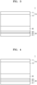
- a solid battery 1 may include: a cathode layer 10; an anode layer 20; and a solid electrolyte layer 30 between the cathode layer 10 and the anode layer 20.
- the solid electrolyte layer 30 may include a first solid electrolyte layer 30a and a second solid electrolyte layer 30b, as shown in FIG. 1 .
- the cathode layer 10 may include: a cathode current collector 11; and a cathode active material layer 12 on one surface (or side) or both (e.g., two opposite) surfaces (or sides) of the cathode current collector 11, wherein the cathode active material layer 12 may include a Li 2 S-containing composite.
- the anode layer 20 may include: an anode current collector 21; and a first anode active material layer 22 on one surface (or side) or both (e.g., two opposite) surfaces (or sides) of the anode current collector 21.
- the solid electrolyte layer 30 may include the first solid electrolyte layer 30a, the second solid electrolyte layer 30b, and a third solid electrolyte layer 30c.
- a total thickness of the solid electrolyte layer 30 may be in a range of about 10 ⁇ m to about 200 ⁇ m
- a thickness of the first solid electrolyte layer 30a and a thickness of the second solid electrolyte layer 30b may each be in a range of about 50 ⁇ m to about 80 ⁇ m.
- a thickness ratio of the first solid electrolyte layer 30a to the second solid electrolyte layer 30b may be in a range of about 10:90 to about 90:10, for example, about 60:40 to about 40:60.
- the cathode layer 10 may include a solid electrolyte represented by Formula 1: Formula 1 (Li 1-b M0 b ) 7-z PS 6-z M3 z , wherein, in Formula 1, M0 may be Na, K, Fe, Mg, Ca, Ag, Cu, Zr, Zn, or one or more combinations thereof, M3 may be an element selected from elements of Group 17 of the periodic table of the elements, 0 ⁇ b ⁇ 0.05, and 0 ⁇ z ⁇ 2.
- the solid electrolyte represented by Formula 1 may be, for example, represented by Formula 1-1: Formula 1-1 (Li 1-b Cu b ) 7-z PS 6-z M3 z , wherein, in Formula 1-1, M3 may be an element selected from elements of Group 17 of the periodic table of the elements, 0 ⁇ b ⁇ 0.05, and 0 ⁇ z ⁇ 2.
- the solid electrolytes represented by Formulae 1 and 1-1 may provide improved lithium ion conductivity.
- the solid electrolyte represented by Formula 1 may provide ion conductivity of 1.0 mS/cm or more, 1.5 mS/cm or more, 2.0 mS/cm or more, 2.5 mS/cm or more, 3.0 mS/cm or more, 3.5 mS/cm or more, 4.0 mS/cm or more, or 5.0 mS/cm or more, at room temperature, for example, about 25 °C.
- the solid electrolyte represented by Formula 1 may provide ion conductivity in a range of about 1.0 mS/cm to about 500 mS/cm, about 1.5 mS/cm to about 400 mS/cm, about 2.0 mS/cm to about 300 mS/cm, about 2.5 mS/cm to about 200 mS/cm, about 3.0 mS/cm to about 150 mS/cm, about 3.5 mS/cm to about 100 mS/cm, about 4.0 mS/cm to about 100 mS/cm, or about 5.0 mS/cm to about 100 mS/cm, at room temperature, for example, about 25 °C.
- the ion transfer between the cathode and the anode may be effectively carried out so that the internal resistance between the cathode and the anode may be reduced.
- the ion conductivity may be measured by utilizing a direct current (DC) polarization method. In some embodiments, the ion conductivity may be measured based on a complex impedance.
- Solid electrolyte layer Solid electrolyte
- the solid electrolyte may include, for example, a sulfide-based solid electrolyte, an oxide-based solid electrolyte, a polymer solid electrolyte, or one or more combinations thereof.
- the solid electrolyte may be, for example, a sulfide-based solid electrolyte.
- the sulfide-based solid electrolyte may include, for example, one or more selected from among: Li 2 S-P 2 S 5 , Li 2 S-P 2 S 5 -LiX (where X is a halogen), Li 2 S-P 2 S 5 -Li 2 O, Li 2 S-P 2 S 5 -Li 2 O-LiI, Li 2 S-SiS 2 , Li 2 S-SiS 2 -LiI, Li 2 S-SiS 2 -LiBr, Li 2 S-SiS 2 -LiCl, Li 2 S-SiS 2 -B 2 S 3 -LiI, Li 2 S-SiS 2 -P 2 S 5 -LiI, Li 2 S-B 2 S 3 , Li 2 S-P 2 S 5 -Z m S n (where m and n are positive
- the sulfide-based solid electrolyte may be, for example, prepared by treating a starting material, such as Li 2 S, P 2 S 5 , and/or the like, by a melting quenching method, a mechanical milling method, and/or the like. Also, after such treatment, heat treatment may be performed thereon.
- the solid electrolyte may be amorphous or crystalline, or may be in a mixed state.
- the solid electrolyte may include, for example, sulfur (S), phosphorus (P), and lithium (Li), at least as a constituent element among the aforementioned sulfide-based solid electrolyte material.
- the sulfide-based solid electrolyte may include, for example, an argyrodite-type or kind (e.g., argyrodite) solid electrolyte represented by Formula 4: Formula 4 Li + 12-n-x A n+ X 2- 6-x Y - x , wherein, in Formula 4, A may be P, As, Ge, Ga, Sb, Si, Sn, Al, In, Ti, V, Nb, or Ta, X may be S, Se, or Te, Y may be Cl, Br, I, F, CN, OCN, SCN, or N 3 , 1 ⁇ n ⁇ 5, and 0 ⁇ x ⁇ 2.
- argyrodite-type or kind e.g., argyrodite
- the sulfide-based solid electrolyte may be, for example, an argyrodite-type or kind compound including one or more selected from among Li 7-x PS 6-x Cl x (where 0 ⁇ x ⁇ 2), Li 7-x PS 6-x Br x (where 0 ⁇ x ⁇ 2), and Li 7-x PS 6-x I x (where 0 ⁇ x ⁇ 2).
- the sulfide-based solid electrolyte may be, for example, an argyrodite-type or kind compound including at least one selected from among Li 6 PS 5 Cl, Li 6 PS 5 Br, and LisPSsl.
- the oxide-based solid electrolyte may include, for example, at least one selected from among Li 1+x+y Al x Ti 2-x Si y P 3-y O 12 (where 0 ⁇ x ⁇ 2 and 0 ⁇ y ⁇ 3), BaTiOs, Pb(Zr,Ti)O 3 (PZT), Pb 1-x La x Zr 1-y Ti y O 3 (PLZT) (where 0 ⁇ x ⁇ 1 and 0 ⁇ y ⁇ 1), Pb(Mg 3 Nb 2/3 )O 3 -PbTiO 3 (PMN-PT), HfO 2 , SrTiO 3 , SnO 2 , CeO 2 , Na 2 O, MgO, NiO, CaO, BaO, ZnO, ZrO 2 , Y 2 O 3 , Al 2 O 3 , TiO 2 , SiO 2 , Li 3 PO 4 , Li x Ti y (PO 4 ) 3 (where 0 ⁇ x ⁇ 2 and 0 ⁇ y ⁇ 3), Li
- the polymer solid electrolyte may include, for example, a mixture of a lithium salt and a polymer or a polymer including an ion-conducting functional group.
- the polymer solid electrolyte may be, for example, a polymer electrolyte not containing a liquid electrolyte.
- the polymer of the polymer solid electrolyte may include, for example, polyethylene oxide (PEO), polyvinylidene fluoride (PVDF), vinylidene fluoride-hexafluoropropylene (PVDF-HFP), a poly(styrene-b-ethylene oxide) block copolymer (PS-PEO), poly(styrene-butadiene), poly(styrene-isoprene-styrene), a poly(styrene-b-divinylbenzene) block copolymer, a poly(styrene-ethylene oxide-styrene) block copolymer, polystyrene sulfonate (PSS), polyvinyl fluoride (PVF), poly(methylmethacrylate) (PMMA), polyethylene glycol(PEG), polyacrylonitrile (PAN), polytetrafluoro ethylene (PTFE), polyethylene dioxythiophene (PEDOT
- any material available as the polymer electrolyte in the art may be utilized.
- the lithium salt any material available in the art as a lithium salt may be utilized.
- the lithium salt may be, for example, LiPF 6 , LiBF 4 , LiSbF 6 , LiAsF 6 , LiClO 4 , LiCF 3 SO 3 , Li(CF 3 SO 2 ) 2 N, LiC 4 F 9 SO 3 , LiAlO 2 , LiAlCl 4 , LiN(C x F 2x+1 SO 2 )(C y F 2y+1 SO 2 )(where x and y are each between 1 to 20), LiCl, Lil, or any mixture thereof.
- the gel electrolyte may be, for example, a gel polymer electrolyte.
- the gel polymer electrolyte may include, for example, a liquid electrolyte and a polymer, or may be, for example, an electrolyte including an organic solvent and a polymer including an ion-conducting functional group.
- the liquid electrolyte may contain, for example, an ionic liquid, a mixture of a lithium salt and an organic solvent, a mixture of an ionic liquid and an organic solvent, or a mixture of a lithium salt, an ionic liquid, and an organic solvent.
- the polymer may be selected from polymers utilized in solid polymer electrolytes.
- the organic solvent may be selected from organic solvents utilized in liquid electrolytes.
- the lithium salt may be selected from lithium salts utilized in solid polymer electrolytes.
- the ionic liquid may have a melting point below the room temperature, and may contain a salt in a liquid state at room temperature or a molten salt at room temperature, each consisting of only ions.
- the ionic liquid may include, for example, one or more selected from compounds including: a) one or more cations selected from among an ammonium-based cation, a pyrrolidinium-based cation, a pyridinium-based cation, a pyrimidinium-based cation, an imidazolium-based cation, a piperidinium-based cation, a pyrazolium-based cation, an oxazolium-based cation, a pyridazinium-based cation, a phosphonium-based cation, a sulfonium-based cation, a triazolium-based cation, and any mixture thereof; and b) one or more anions selected from among BF 4 - , PF 6 - , AsF 6 - , SbF 6 - , AlCl 4 - , HSO 4 - , ClO 4 - , CH 3
- the solid electrolyte layer 30 may include, for example, a binder.
- the binder included in the solid electrolyte layer 30 may include, for example, a styrene-butadiene rubber (SBR), polytetrafluoroethylene (PTFE), polyvinylidene fluoride (PVDF), polyethylene, and/or the like, but embodiments of the present disclosure are not limited thereto. Any material available as a binder in the art may be utilized.
- the binder included in the solid electrolyte layer 30 may be the same as or different from binders included in the cathode active material layer 12 and the anode active material layer 22. In some embodiments, the binder may not be provided and utilized.
- Cathode layer Cathode active material
- the cathode layer 10 may include: a cathode current collector 11; and a cathode active material layer 12 disposed on one surface (or side) or both (e.g., two opposite) surfaces (or sides) of the cathode current collector 11.
- the cathode active material layer 12 may include a M 2 S-containing composite as a cathode active material (e.g., a composite cathode active material).
- the M 2 S-containing composite may include a composite of M 2 S and a carbon-based material, a composite of M 2 S, a carbon-based material, and a solid electrolyte, a composite of M 2 S and a solid electrolyte, a composite of M 2 S, a carbon-based material, and an alkali metal salt, a composite of M 2 S and an alkali metal salt, a composite of M 2 S and a metal carbide, a composite of M 2 S, a carbon-based material, and a metal carbide, a composite of M 2 S and a metal nitride, a composite of M 2 S, a carbon-based material, and a metal nitride, or any combination thereof.
- the composite cathode active material may include: M 2 S; and an alkali metal salt, wherein M may be an alkali metal, and the alkali metal may be Li or Na.
- the M 2 S-containing composite may be a Li 2 S-containing composite
- the Li 2 S-containing composite may include a composite of Li 2 S and a carbon-based material, a composite of Li 2 S, a carbon-based material, and a solid electrolyte, a composite of Li 2 S and a solid electrolyte, a composite of Li 2 S, a carbon-based material, and a lithium salt, a composite of Li 2 S and a lithium salt, a composite of Li 2 S and a metal carbide, a composite of Li 2 S, a carbon-based material, and a metal carbide, a composite of Li 2 S and a metal nitride, a composite of Li 2 S, a carbon-based material, and a metal nitride, or any combination thereof.
- the composite cathode active material may include a composite (cathode active material) of M 2 S, an alkali metal salt, and a carbon-based material, wherein M may be an alkali metal.
- the alkali metal may be lithium (Li) or sodium (Na).
- M 2 S may be, for example, Li 2 S or Na 2 S. in one or more embodiments, a size of M 2 S crystallites obtained from an X-ray diffraction (XRD) spectrum of the composite may be less than or equal to about 9.9 nanometers (nm).
- the size of M 2 S crystallites obtained from the XRD spectrum of the composite may be, for example, about 9.85 nm or less, about 9.83 nm or less, about 9.8 nm or less, about 9.5 nm or less, about 9.0 nm or less, or about 8.5 nm or less.
- the composite may include a solid solution of M 2 S and the alkali metal salt within the ranges above.
- the size of M 2 S crystallites obtained from an X-ray diffraction (XRD) spectrum of the composite may be, for example, in a range of about 1 nm to less than 9.9 nm, about 1 nm to about 9.8 nm, about 2 nm to about 9.8 nm, about 2 nm to about 9.5 nm, about 2 nm to about 9.0 nm, about 2 nm to about 8.5 nm, or about 3 nm to about 8.5 nm.
- the composite may include a solid solution of M 2 S and the alkali metal salt within the ranges above.
- M 2 S forms a composite with the alkali metal salt and carbon-based material
- the ion conductivity and electronic conductivity of the M 2 S may be improved concurrently (e.g., simultaneously).
- the composite includes the alkali metal salt
- the ion conductivity of the composite cathode active material may be improved, and the internal resistance of a cathode and a lithium battery that include the composite cathode active material may be reduced.
- the composite includes the carbon-based material
- the electronic conductivity of the composite cathode active material may be improved, and the internal resistance of a cathode and a lithium battery that include the composite cathode active material may be reduced.
- the composite may include M 2 S crystallites, and the volume change of the M 2 S crystallites during charging and discharging may be alleviated by reducing the size of the M 2 S crystallites to 21 nm or less.
- the volume change affected by a single M 2 S crystallite decreases, and thus the overall volume change of the composite during charging and discharging may be alleviated.
- the grain boundary among a plurality of M 2 S crystallites may be able to more easily accommodate the volume change of the M 2 S crystallites during charging and discharging, and thus the volume change of the composite during charging and discharging may be alleviated.
- the possibility of defects, such as cracks and/or the like caused by the volume change during charging and discharging, during charging and discharging of the composite may be reduced.
- the composite cathode active material includes the aforementioned composite
- the cycle characteristics of a lithium battery including the composite cathode active material may be improved.
- the lifespan characteristics of a lithium battery including the aforementioned composite cathode active material may be improved.
- a contact area between the M 2 S crystallites and the alkali metal salt and/or the carbon-based material may be further increased. If (e.g., when) the contact area between the M 2 S crystallites and the alkali metal salt and/or the carbon-based material increases, the ion conductivity of the composite and/or the battery conductivity may be further improved. If (e.g., when) the composite cathode active material includes the aforementioned composite, the reversibility of an electrode reaction in a battery including the composite cathode active material may be improved. As a result, the specific capacity of the composite cathode active material may be increased.
- the ion conductivity of the composite may be improved.
- a solid solution of M 2 S and the alkali metal salt includes alkali metal ions disposed in the M 2 S crystallites, and thus the ion conductivity of the solid solution of M 2 S and the alkali metal salt may be improved compared to the ion conductivity of the M 2 S.
- the ion conductivity of the composite may be improved, and the internal resistance of the composite may be reduced.
- the composite cathode active material includes the aforementioned composite
- the cycle characteristics of a lithium battery including the composite cathode active material may be improved.
- the high-rate characteristics of a secondary battery including the aforementioned composite cathode active material may be improved.
- the Li 2 S-alkali metal salt-carbon-based material composite may be distinguished from a simple mixture of Li 2 S, an alkali metal salt, and a carbon-based material.
- the simple mixture of Li 2 S, the alkali metal salt, and the carbon-based material may fail to maintain a dense interface among the Li 2 S, the alkali metal salt, and the carbon-based material, resulting in high interfacial resistance. As a result, the lifespan characteristics of a secondary battery may be degraded.
- the composite may include M 2 S.
- the M 2 S may have a high theoretical capacity, and thus an all solid secondary battery having high energy density may be provided. However, because the M 2 S has low ion conductivity and/or electronic conductivity, the M 2 S may form a complex with an alkali metal salt and a carbon-based material to overcome these shortcomings.
- an amount of the M 2 S may be, for example, in a range of about 10 wt% to about 80 wt% or about 20 wt% to about 70 wt%, based on the total weight of the composite, in some embodiments, the amount of the M 2 S may be in a range of about 30 wt% to about 60 wt% or about 40 wt% to about 60 wt%, based on the total weight of the composite. If (e.g., when) the amount of the M 2 S excessively increases, the ion conductivity and/or electronic conductivity of the composite may not be easily improved. If (e.g., when) the amount of the M 2 S is excessively low, the energy density of the composite may be reduced.
- the composite may include an alkali metal salt.
- the alkali metal salt may be, for example, a sulfur (S)-free compound.
- the alkali metal salt may be, for example, a binary compound or a ternary compound, in some embodiments, the alkali metal salt may be, for example, a binary compound including (e.g., consisting of) an alkali metal and one element selected from elements of Groups 13 to 17 of the periodic table of the elements. in some embodiments, the alkali metal salt may be, for example, a ternary compound including (e.g., consisting of) an alkali metal and two elements selected from elements of Groups 13 to 17 of the periodic table of the elements.
- the alkali metal salt may be, for example, a lithium salt.
- the binary compound including a lithium salt may include, for example, Lil, LiBr, LiCl, LiF, LiH, Li 2 O, Li 2 Se, Li 2 Te, LisN, LisP, LisAs, LisSb, Li 3 Al 2 , LiBs, or any combination thereof.
- the ternary compound including a lithium salt may include, for example, Li 3 OCl, LiPF 6 , LiBF 4 , LiSbF 6 , LiAsF 6 , LiClO 4 , LiAlO 2 , LiAlCl 4 , LiNO 3 , Li 2 CO 3 , LiBH 4 , Li 2 SO 4 , Li 3 BO 3 , Li 3 PO 4 , Li 4 NCl, Li 5 NCl 2 , Li 3 BN 2 , or any combination thereof. If (e.g., when) the composite includes such a lithium salt, the ion conductivity of the composite may be further improved. Such a lithium salt may, for example, more easily form a solid solution with Li 2 S in the composite.
- the alkali metal salt may be, for example, a sodium salt.
- the binary compound including a sodium salt may include, for example, Nal, NaBr, NaCl, NaF, Na 2 O, Na 2 Se, Na 3 N, Na 3 P, Na 3 As, Na 3 Sb, Na 3 Al 2 , NaB 3 , or any combination thereof.
- the ternary compound including a sodium salt may include, for example, Na 3 OCl, NaBF 4 , NaPF 6 , NaAsF 6 , NaClO 4 , NaNO 3 , NaAlO 2 , NaAlCl 4 , NaNO 3 , Na 2 CO 3 , NaBH 4 , Na 2 SO 4 , Na 3 BO 3 , Na 3 PO 4 , Na 4 NCl, Na 5 NCl 2 , Na 3 BN 2 , or any combination thereof. If (e.g., when) the composite includes such a sodium salt, the ion conductivity of the composite may be further improved. Such a sodium salt may, for example, more easily form a solid solution with Na 2 S in the composite.
- An amount of the alkali metal salt in the composite may be in a range of about 1 wt% to about 40 wt%, about 5 wt% to about 35 wt%, about 10 wt% to about 35 wt%, about 15 wt% to about 35 wt%, about 20 wt% to about 35 wt%, or about 25 wt% to about 35 wt%, based on the total weight of the composite. If (e.g., when) the amount of the alkali metal salt excessively increases, the energy density of a secondary battery may be reduced.
- the amount of the alkali metal salt is excessively low, the ion conductivity of the composite may decrease, and the internal resistance of the composite cathode active material may then increase. As a result, the cycle characteristics of a secondary battery may be degraded.
- the molar ratio of the M 2 S to the alkali metal salt in the composite may be, for example, in a range of about 50:50 to about 95:5, about 60:40 to about 95:5, about 60:40 to about 90:10, about 65:35 to about 90:10, about 65:35 to about 85:15, or about 70:30 to about 85:15.
- the molar ratio of the M 2 S to the alkali metal salt in the composite may be, for example, in a range of about 50:50 to about 95:5, about 50:50 to about 90:10, about 50:50 to about 85:15, about 50:50 to about 80:20, about 50:50 to about 75:25, or about 50:50 to about 70:30. If (e.g., when) the molar ratio of the M 2 S to the alkali metal salt is within the ranges above, the cycle characteristics of a secondary battery including the composite cathode active material may be further improved.
- the molar ratio of the M 2 S to the alkali metal salt is excessively high, the effect of improving the ion conductivity by the alkali metal salt may be negligible. If (e.g., when) the molar ratio of the M 2 S to the alkali metal salt is excessively low, the energy density of a secondary battery including the composite cathode active material may be degraded.
- a molar ratio of the Li 2 S to the lithium salt in the composite may be, for example, in a range of about 50:50 to about 95:5, about 60:40 to about 95:5, about 60:40 to about 90:10, about 65:35 to about 90:10, about 65:35 to about 85:15, or about 70:30 to about 85:15.
- the molar ratio of the Li 2 S to the lithium salt in the composite may be, for example, in a range of about 50:50 to about 95:5, about 50:50 to about 90:10, about 50:50 to about 85:15, about 50:50 to about 80:20, about 50:50 to about 75:25, or about 50:50 to about 70:30.
- the cycle characteristics of a lithium battery including the composite cathode active material may be further improved. If (e.g., when) the molar ratio of the Li 2 S to the lithium salt is excessively high, the effect of improving the ion conductivity by the lithium salt may be negligible. If (e.g., when) the molar ratio of the Li 2 S to the lithium salt is excessively low, the energy density of a lithium battery including the composite cathode active material may be degraded.
- a molar ratio of the Na 2 S to the sodium salt in the composite may be, for example, in a range of about 50:50 to about 95:5, about 60:40 to about 95:5, about 60:40 to about 90:10, about 65:35 to about 90:10, about 65:35 to about 85:15, or about 70:30 to about 85:15.
- the molar ratio of the Na 2 S to the sodium salt in the composite may be, for example, in a range of about 50:50 to about 95:5, about 50:50 to about 90:10, about 50:50 to about 85:15, about 50:50 to about 80:20, about 50:50 to about 75:25, or about 50:50 to about 70:30.
- the cycle characteristics of a sodium battery including the composite cathode active material may be further improved. If (e.g., when) the molar ratio of the Na 2 S to the sodium salt is excessively high, the effect of improving the ion conductivity by the sodium salt may be negligible. If (e.g., when) the molar ratio of the Na 2 S to the sodium salt is excessively low, the energy density of a sodium battery including the composite cathode active material may be degraded.
- the composite includes a carbon-based material.
- the carbon-based material e.g., a carbon atom-containing material
- any material utilized as a conductive material in the art may be utilized.
- the carbon-based material may include, for example, crystalline carbon, amorphous carbon, or a combination thereof.
- the carbon-based material may be, for example, a sintered product of a carbon precursor.
- the carbon-based material may be, for example, a carbon-based nanostructure.
- the carbon nanostructure may be, for example, a one-dimensional carbon nanostructure, a two-dimensional carbon nanostructure, a three-dimensional carbon nanostructure, or one or more combinations thereof.
- the carbon nanostructure may be, for example, carbon nanotubes, carbon nanofibers, carbon nanobelts, carbon nanorods, graphene, or one or more combinations thereof.
- the carbon-based material may be, for example, a porous carbon-based material or a non-porous carbon-based material.
- the porous carbon-based material may include, for example, periodic and ordered two-dimensional or three-dimensional pores.
- the porous carbon-based material may be: for example, carbon black, such as Ketjen black, acetylene black, Denka black, thermal black, channel black, etc.; graphite; activated carbon; or one or more combinations thereof.
- the carbon-based material may be, for example, in the form of particles, sheets, flakes, etc., but the form is not limited thereto. Any material available as the carbon-based material in the art may be utilized.
- a first peak appearing at a diffraction angle 2 ⁇ of 27° ⁇ 2.0° corresponding to a (111) crystal surface of the M 2 S may have a first diffraction angle
- a second peak appearing at a diffraction angle 2 ⁇ of 27° ⁇ 2.0° corresponding to a (111) crystal surface of the M 2 S may have a second diffraction angle, wherein the first diffraction angle may be smaller than the second diffraction angle.
- a position of the first peak may be shifted to a low angle compared to a position of the second peak.
- the M 2 S-alkali metal salt-carbon-based material composite may then have a reduced crystallite size compared to the M 2 S utilized in the preparation of the composite.
- the reduced crystallite size of the M 2 S-alkali metal salt-carbon-based material composite may lead to a small change in volume of the crystallites during charging and discharging, and thus the volume change of the composite including a plurality of crystallites during charging and discharging may be alleviated.
- the occurrence of defects, such as cracks and/or the like, of the composite cathode active material including the composite during charging and discharging may be suppressed or reduced. As a result, the cycle characteristics of a secondary battery including the composite cathode active material may be improved.
- the first peak appearing at the diffraction angle 2 ⁇ of 27° ⁇ 2.0° corresponding to the (111) crystal surface of the M 2 S may have a first full width at half maximum (FWHM1)
- the second peak appearing at the diffraction angle 2 ⁇ of 27° ⁇ 2.0° corresponding to the (111) crystal surface of the M 2 S may have a second full width at half maximum (FWHM2), wherein the FWHM1 may be greater than the FWHM2.
- the M 2 S-alkali metal salt-carbon-based material composite may then have an increased lattice strain compared to the M 2 S utilized in the preparation of the composite.
- the M 2 S-alkali metal salt-carbon-based material composite may have an increased lattice strain.
- the M 2 S-alkali metal salt-carbon-based material composite may have increased FWHM compared to that of the M 2 S utilized in the preparation of the composite, and accordingly, the ion (e.g., ionic) conductivity of the composite cathode active material including the composite may be further improved.
- the internal resistance of a secondary battery including the composite cathode active material may be reduced, and the cycle characteristics of the same may be improved.
- the FWHM1 may be, for example, 1° or greater, 1.05° or greater, 1.10° or greater, or 1.15° or greater. If (e.g., when) the composite has the FWHM1 within the ranges above, the ion conductivity of the composite cathode active material including the composite may be further improved. The internal resistance of a secondary battery including the composite cathode active material may be reduced, and the cycle characteristics of the second battery may be improved.
- the Mohs hardness of each of the alkali metal salt and the carbon-based material may be greater than that of the M 2 S.
- the Mohs hardness of the M 2 S may be, for example, 0.6 or less.
- the Mohs hardness of the Li 2 S may be, for example, 0.6 or less.
- the Mohs hardness of the alkali metal salt may be 0.7 or greater, 0.8 or greater, 0.9 or greater, 1.0 or greater, 1.5 or greater, or 2.0 or greater. If (e.g., when) the alkali metal salt has the Mohs hardness within the ranged above, the M 2 S may be more easily pulverized during a milling process, and a solid solution of the M 2 S and the alkali metal salt may be more easily formed.
- the Mohs hardness of the LiI may be, for example, 2.0.
- the Mohs hardness of the Nal may be, for example, 2.1.
- the Mohs hardness of the carbon-based material may be 0.7 or greater, 0.8 or greater, 0.9 or greater, 1.0 or greater, 1.2 or greater, or 1.5 or greater. If (e.g., when) the carbon-based material has the Mohs hardness within the ranged above, the M 2 S may be more easily pulverized during a milling process, and the M 2 S-alkali metal salt-carbon-based material composite may be more easily formed.
- the Mohs hardness of carbon nanofiber (CNF) may be, for example, 1.5.
- a particle size of the composite cathode active material i.e., the particle size of the composite
- the particle size of the composite may be, for example, 2 ⁇ m or less, 1.5 ⁇ m or less, or 1 ⁇ m or less.
- the particle size of the composite may be, for example, in a range of about 0.1 ⁇ m to 2 ⁇ m, about 0.1 ⁇ m to about 1.5 ⁇ m, or about 0.1 ⁇ m to about 1 ⁇ m. If (e.g., when) the particle size of the composite is within the ranges above, the volume change during charging and discharging may be suppressed or reduced, and accordingly, the deterioration of the composite cathode active material including the composite may be suppressed or reduced.
- the particle size of the composite excessively increases, the volume change of the composite during charging and discharging may increase, and accordingly, the deterioration of the composite cathode active material including the composite may be accelerated. As a result, the cycle characteristics of a secondary battery including the composite cathode active material may be degraded.
- a secondary battery including the composite cathode active material may have improved cycle characteristics, for example improved lifespan characteristics.
- the particle size of the composite e.g., a particle diameter of the composite, may be measured by utilizing, for example, a laser diffraction method, a scanning electron microscope, and/or the like.
- the particle size of the composite may be, for example, an arithmetic average of the particle diameters of a plurality of particles measured by utilizing a software from images obtained by a scanning electron microscope.
- the composite may include the carbon-based material, and the carbon-based material may include, for example, a fibrous carbon-based material. If (e.g., when) the composite includes such a fibrous carbon-based material, the electronic conductivity of the composite may be further improved. If (e.g., when) the composite includes the fibrous carbon-based material, the electronic conduction from the surface of the composite (e.g., composite particles) to the inner part of the composite (e.g., composite particles) may be easily facilitated. The internal resistance of the composite cathode active material including the composite may be reduced, and accordingly, the cycle characteristics of a secondary battery including the composite cathode active material may be further improved.
- an aspect ratio of the fibrous carbon-based material may be, for example, 2 or greater, 3 or greater, 4 or greater, 5 or greater, 10 or greater, or 20 or greater.
- the aspect ratio of the fibrous carbon-based material may be, for example, in a range of about 2 to about 30, about 3 to about 30, about 4 to about 30, about 5 to about 30, about 10 to about 30, or about 20 to about 30.
- the aspect ratio of the fibrous carbon-based material may be, for example, in a range of about 2 to about 30, about 2 to about 20, about 2 to about 10, about 2 to about 8, about 2 to about 5, or about 2 to about 4. If (e.g., when) the aspect ratio of the fibrous carbon-based material is within the ranges above, the overall electronic conductivity of the composite may be improved, and accordingly, an imbalance of the local electronic conductivity in the composite may be further alleviated.
- the fibrous carbon-based material may include, for example, a carbon nanostructure.
- the carbon nanostructure may include, for example, carbon nanofibers (CNFs), carbon nanotubes (CNTs), carbon nanobelts, carbon nanorods, or any combination thereof.
- the carbon nanostructure may form a primary carbon nanostructure (e.g., a primary particle or structure) including (e.g., consisting of) one carbon nanostructure and a secondary carbon nanostructure (e.g., a secondary particle or structure) including (e.g., consisting of) a plurality of carbon nanostructures aggregated.
- a primary carbon nanostructure e.g., a primary particle or structure
- a secondary carbon nanostructure e.g., a secondary particle or structure
- a diameter of the primary carbon nanostructure may be, for example, in a range of about 1 nm to about 200 nm, about 1 nm to about 150 nm, about 1 nm to about 100 nm, about 1 nm to about 50 nm, about 1 nm to about 30 nm, or about 1 nm to about 20 nm.
- a length of the primary carbon nanostructure may be, for example, in a range of about 10 nm to about 2 ⁇ m, about 10 nm to about 1.5 ⁇ m, about 10 nm to about 1 ⁇ m, about 10 nm to about 500 nm, about 10 nm to about 400 nm, about 10 nm to about 300 nm, about 10 nm to about 200 nm, or about 10 nm to about 100 nm.
- the diameter and length of the primary carbon nanostructure may be measured from images obtained by utilizing a scanning electron microscope (SEM) or a transmission electron microscope (TEM). In some embodiments, the diameter and/or length of the primary carbon nanostructure may be measured by a laser diffraction method.
- the secondary carbon nanostructure may be, for example, a structure (e.g., a secondary particle or structure) formed by the primary carbon nanostructures (e.g., primary particles or structures) that are wholly or partially aggregated to form bundles or ropes.
- the secondary carbon nanostructure may include, for example, a bundle-type or kind carbon nanostructure, a rope-type or kind carbon nanostructure, or a combination thereof.
- a diameter of the secondary carbon nanostructure may be, for example, in a range of about 2 nm to about 200 nm, about 3 nm to about 150 nm, about 5 nm to about 100 nm, about 5 nm to about 50 nm, about 5 nm to about 30 nm, or about 5 nm to about 20 nm.
- a length of the secondary carbon nanostructure may be, for example, in a range of about 20 nm to about 2 ⁇ m, about 30 nm to about 1.5 ⁇ m, about 50 nm to about 1 ⁇ m, about 50 nm to about 500 nm, about 50 nm to about 400 nm, about 50 nm to about 300 nm, about 50 nm to about 200 nm, or about 50 nm to about 100 nm or more.
- the diameter and length of the secondary carbon nanostructure may be measured from images obtained by an SEM or an optical microscope. In some embodiments, the diameter and/or length of the secondary carbon nanostructure may be measured by a laser diffraction method.
- the secondary carbon nanostructure may be, for example, dispersed in a solvent and/or the like to be converted into the primary carbon nanostructure, and then, may be utilized for the preparation of the composite.
- the composite may include, for example, about 10 parts by weight to about 80 parts by weight of the M 2 S, about 1 part by weight to about 40 parts by weight of the alkali metal salt, and about 1 part by weight to about 20 parts by weight of the carbon-based material, based on 100 parts by weight of the composite.
- the amount of the M 2 S included in the composite may be, for example, in a range of about 10 parts by weight to about 80 parts by weight, about 20 parts by weight to about 70 parts by weight, about 30 parts by weight to about 60 parts by weight, or about 40 parts by weight to 60 parts by weight, based on 100 parts by weight of the composite.
- the amount of the alkali metal salt included in the composite may be, for example, in a range of about 10 parts by weight to about 40 parts by weight, about 15 parts by weight to about 40 parts by weight, about 20 parts by weight to about 40 parts by weight, or about 25 parts by weight to 35 parts by weight, based on 100 parts by weight of the composite.
- the amount of the carbon-based material included in the composite may be, for example, in a range of about 1 part by weight to about 20 parts by weight, about 5 parts by weight to about 20 parts by weight, or about 5 parts by weight to 15 parts by weight, based on 100 parts by weight of the composite. If (e.g., when) the composite includes the M 2 S, the alkali metal salt, and the carbon-based material as described above, the composite cathode active material including the composite may provide excellent or suitable ion conductivity and/or electronic conductivity.
- the M 2 S-containing composite may be a Li 2 S-containing composite
- the Li 2 S-containing composite may include a composite of Li 2 S, a lithium salt, and a carbon-based material, the composite including about 10 parts by weight to about 80 parts by weight of the Li 2 S, about 1 part by weight to about 40 parts by weight of the lithium salt, and about 1 part by weight to about 20 parts by weight of the carbon-based material, based on 100 parts by weight of the composite.
- the ion conductivity of the composite may be, for example, 1 ⁇ 10 -5 S/cm or more, 2 ⁇ 10 -5 S/cm or more, 4 ⁇ 10 -5 S/cm or more, 6 ⁇ 10 -5 S/cm or more, 8 ⁇ 10 -5 S/cm or more, or 1 ⁇ 10 -4 S/cm or more, at 25 °C.
- the ion conductivity may be measured by, for example, electrochemical impedance spectroscopy, a direct current (DC) polarization method, and/or the like. If (e.g., when) the composite has the ion conductivity within the ranges above, the internal resistance of the composite cathode active material including the composite may be reduced.
- the cycle characteristics of a secondary battery including the composite cathode active material may be then improved.
- the electronic conductivity of the composite may be, for example, 1 ⁇ 10 -5 S/cm or more, 2 ⁇ 10 -5 S/cm or more, 4 ⁇ 10 -5 S/cm or more, 6 ⁇ 10 -5 S/cm or more, 8 ⁇ 10 -5 S/cm or more, or 1 ⁇ 10 -4 S/cm or more, at 25 °C.
- the electronic conductivity may be measured by, for example, electrochemical impedance spectroscopy, a DC polarization method, and/or the like. If (e.g., when) the composite has the electronic conductivity within the ranges above, the internal resistance of the composite cathode active material including the composite may be reduced. The cycle characteristics of a secondary battery including the composite cathode active material may be then improved.
- Cathode layer Cathode active material
- the cathode may include: a cathode current collector; and a cathode active material layer on one surface (or side) or both (e.g., two opposite) surfaces (or sides) of the cathode current collector.
- the cathode active material layer may include the aforementioned composite cathode active material and a solid electrolyte. If (e.g., when) the cathode includes the composite cathode active material and the solid electrolyte, the internal resistance of the cathode may be further reduced. In this regard, the cycle characteristics of a secondary battery including the cathode may be further improved.
- the cathode layer 10 may include: the cathode current collector 11; and the cathode active material layer 12 on one surface (or side) or both (e.g., two opposite) surfaces (or sides) of the cathode current collector 11.
- the cathode active material layer 12 may include the aforementioned composite cathode active material and a solid electrolyte.
- the composite cathode active material may be included in the amount in a range of about 40 parts by weight to about 90 parts by weight, about 40 parts by weight to about 80 parts by weight, about 50 parts by weight to about 80 parts by weight, or about 50 parts by weight to about 70 parts by weight, based on 100 parts by weight of the cathode active material layer 12. If (e.g., when) the amount of the composite cathode active material excessively decreases, the energy density of the all solid secondary battery 1 may be reduced. If (e.g., when) the amount of the composite cathode active material excessively increases, the deterioration of the cathode may be accelerated due to the volume changes in the cathode during charging and discharging. As a result, the cycle characteristics of the secondary battery 1 may be degraded.
- the cathode active material layer 12 may additionally include one or more of other cathode active materials in addition to the aforementioned composite cathode active material.
- the other cathode active material may include, for example, a Li 2 S-containing composite.
- the Li 2 S-containing composite may include, for example, a composite of Li 2 S and a carbon-based material, a composite of Li 2 S, a carbon-based material, and a solid electrolyte, a composite of Li 2 S and a solid electrolyte, a composite of Li 2 S and a lithium salt, a composite of Li 2 S and a metal carbide, a composite of Li 2 S, a carbon-based material, and a metal carbide, a composite of Li 2 S and a metal nitride, a composite of Li 2 S, a carbon-based material, and a metal nitride, or any combination thereof.
- the composite of Li 2 S and a carbon-based material may include a carbon-based material, in addition to Li 2 S.
- the carbon-based material may be understood by referring to the carbon-based material of the aforementioned composite cathode active material.
- a method of preparing the composite of Li 2 S and the carbon-based material may be a dry method, a wet method, or a combination thereof, but embodiments of the present disclosure are not limited thereto. Any method available in the art may be utilized.
- a method of preparing the composite of Li 2 S and the carbon-based material may be, for example, milling, heat treatment, deposition, and/or the like, but embodiments of the present disclosure are not limited thereto. Any method available in the art may be utilized.
- the composite of Li 2 S, a carbon-based material, and a solid electrolyte may include a carbon-based material and a solid electrolyte, in addition to Li 2 S.
- the carbon-based material may be understood by referring to the carbon-based material of the aforementioned composite of Li 2 S and the carbon-based material.
- the solid electrolyte may be, for example, any material utilized as an ionic conductive material in the art.
- the solid electrolyte may be, for example, an inorganic solid electrolyte.
- the solid electrolyte may be, for example, a crystalline solid electrolyte, an amorphous solid electrolyte, or a combination thereof.
- the solid electrolyte may be, for example, a sulfide-based solid electrolyte, an oxide-based solid electrolyte, or any combination thereof.
- the sulfide-based solid electrolyte may include, for example, Li, S, and P, and may optionally further include a halogen element.
- the sulfide-based solid electrolyte may be selected from sulfide-based solid electrolytes utilized in an electrolyte layer.
- the sulfide-based solid electrolyte may have, for example, ion conductivity of 1 ⁇ 10 -5 S/cm or more at room temperature.
- the oxide-based solid electrolyte may include, for example, Li, O, and a transition metal element, and may optionally further include other elements.
- the oxide-based solid electrolyte may be, for example, a solid electrolyte having ion conductivity of 1 ⁇ 10 -5 S/cm or more at room temperature.
- the oxide-based solid electrolyte may be selected from oxide-based solid electrolytes utilized in an electrolyte layer.
- the composite of Li 2 S and a solid electrolyte may include a solid electrolyte, in addition to Li 2 S.
- the solid electrolyte may be understood by referring to the solid electrolyte of the aforementioned composite of Li 2 S, the carbon-based material, and the solid electrolyte.
- the composite of Li 2 S and a lithium salt may include Li 2 S and a lithium salt.
- the lithium salt may be understood by referring to the lithium salt of the aforementioned composite cathode active material.
- the lithium salt may be, for example, a lithium halide compound including one or more selected from among LiF, LiCl, LiBr, and Lil.
- the composite of Li 2 S and the lithium salt may be, for example, a composite of Li 2 S and a lithium halide. If (e.g., when) the composite of Li 2 S and the lithium salt includes the lithium halide compound, the further improved ion conductivity may be provided.
- the composite of Li 2 S and the lithium salt may be distinguished from a simple mixture of Li 2 S and the lithium salt.
- the simple mixture of Li 2 S and the lithium salt may fail to maintain a dense interface between the Li 2 S and the lithium salt, resulting in high interfacial resistance. As a result, the lifespan characteristics of a secondary battery may be degraded.
- the composite of Li 2 S and a metal carbide may include a metal carbide, in addition to Li 2 S.
- the metal carbide may be, for example, a two-dimensional metal carbide.
- the two-dimensional metal carbide may be, for example, represented by M n+1 C n T x (wherein M may be a transition metal, T may be an end group, and may be O, OH, and/or F, n may be 1, 2, or 3, and x may represent the number of end groups).
- the two-dimensional metal carbide may be, for example, Ti 2 CT x , (Ti 0.5 , Nb 0.5 ) 2 CT x , Nb 2 CT x , V 2 CT x , Ti 3 C 2 T x , (V 0.5 , Cr 0.5 ) 3 C 2 T x , Ti 3 CNT x , Ta 4 C 3 T x , Nb 4 C 3 T x , or one or more combinations thereof.
- the surfaces of the two-dimensional metal carbide may be terminated with O, OH, and/or F.
- the composite of Li 2 S, a carbon-based material, and a metal carbide may include a carbon-based material and a metal carbide, in addition to Li 2 S.
- the carbon-based material may be understood by referring to the carbon-based material of the aforementioned composite of Li 2 S and the carbon-based material.
- the metal carbide may be understood by referring to the metal carbide of the aforementioned composite of Li 2 S and the metal carbide.
- the composite of Li 2 S and a metal carbide may include a metal carbide, in addition to Li 2 S.
- the metal nitride may be, for example, a two-dimensional metal nitride.
- the two-dimensional metal nitride may be, for example, represented by M n+1 N n T x (wherein M may be a transition metal, T may be an end group, and may be O, OH, and/or F, n may be 1, 2, or 3, and x may represent the number of end groups).
- M may be a transition metal
- T may be an end group
- n may be 1, 2, or 3
- x may represent the number of end groups.
- the surfaces of the two-dimensional metal nitride may be terminated with O, OH, and/or F.
- the composite of Li 2 S, a carbon-based material, and a metal nitride may include a carbon-based material and a metal nitride, in addition to Li 2 S.
- the carbon-based material may be understood by referring to the carbon-based material of the aforementioned composite of Li 2 S and the carbon-based material.
- the metal carbide may be understood by referring to the metal carbide of the aforementioned composite of Li 2 S and the metal carbide.
- the cathode active material layer 12 may further include, for example, a sulfide-based compound that is distinguished from the aforementioned cathode active material.
- the sulfide-based compound may be, for example, a compound including: a metal element other than Li; and a sulfur element.
- the sulfide-based compound may be, for example, a compound including: a metal element belonging to Groups 1 to 14 of the periodic table of the elements and having an atomic weight of 10 or more; and a sulfur element.
- the sulfide-based compound may be, for example, FeS 2 , VS 2 , NaS, MnS, FeS, NiS, CuS, or one or more combinations thereof.
- the cycle characteristics of the all solid secondary battery 1 may be further improved.
- An amount of the sulfide-based compound included in the cathode active material layer 12 may be 10 wt% or less, 5 wt% or less, 3 wt% or less, or 1 wt% or less, based on a total weight of the cathode active material layer 12.
- the cathode active material layer 12 may further include, for example, a solid electrolyte (e.g., in a form of particles).
- the solid electrolyte may be, for example, a sulfide-based solid electrolyte.
- the solid electrolyte included in the cathode layer 10 may be identical to or different from the solid electrolyte included in the electrolyte layer 30. Details on the solid electrolyte may be understood by referring to the electrolyte layer 30.
- the solid electrolyte included in the cathode active material layer 12 may have a smaller average particle diameter D50 than the solid electrolyte included in the electrolyte layer 30.
- the average particle diameter D50 of the solid electrolyte included in the cathode active material layer 12 may be 90 % or less, 80 % or less, 70 % or less, 60 % or less, 50 % or less, 40 % or less, 30 % or less, or 20 % or less, with respect to the average particle diameter D50 of the solid electrolyte included in the electrolyte layer 30.
- the average particle diameter D50 may be, for example, a median particle diameter D50.
- the median particle diameter D50 may be a particle size corresponding to a 50 % cumulative volume calculated from particles having a small particle size to particles having a large particle size in a particle size distribution measured by, for example, a laser diffraction method.
- the solid electrolyte may be included in an amount in a range of about 10 parts by weight to about 60 parts by weight, about 10 parts by weight to about 50 parts by weight, about 20 parts by weight to about 50 parts by weight, or about 30 parts by weight to about 50 parts by weight, based on 100 parts by weight of the cathode active material layer 12. If (e.g., when) the amount of the solid electrolyte excessively decreases, the cycle characteristics of the all solid secondary battery 1 may be degraded due to an increase in the internal resistance of the cathode layer 10. If (e.g., when) the amount of the solid electrolyte excessively increases, the energy density of the all solid secondary battery 1 may be reduced.
- the cathode active material layer 12 may further include a conductive material.
- the conductive material may be, for example, a carbon-based conductive material, a metal-based conductive material, or any combination thereof.
- the carbon-based conductive material may be, for example, graphite, carbon black, acetylene black, Ketjen black, carbon fibers, or one or more combinations thereof, but embodiments of the present disclosure are not limited thereto. Any material available as a carbon-based conductive material in the art may be utilized.
- the metal-based conductive material may be metal powder, metal fibers, or any combination thereof, but embodiments of the present disclosure are not limited thereto. Any material available as a metal-based conductive material in the art may be utilized.
- An amount of the conductive material included in the cathode active material layer 12 may be, for example, in a range of about 1 wt% to about 30 wt%, about 1 wt% to about 20 wt%, or about 1 wt% to about 10 wt%, based on a total weight of the cathode active material layer 12.
- the cathode active material layer 12 may include a carbon-based material, and the carbon-based material may be disposed only on/in the composite cathode active material.
- the cathode active material layer 12 may not additionally include a separate carbon-based material other than the composite cathode active material including the carbon-based material. If (e.g., when) the cathode active material layer 12 does not additionally include a separate carbon-based material, the energy density of the cathode layer 10 and the all solid secondary battery 1 may be improved, and a preparation process of the battery may be simplified.
- the cathode active material layer 12 may further include a binder.
- the binder may be, for example, a styrene butadiene rubber(SBR), polytetrafluoroethylene, polyvinylidene fluoride, polyethylene, and/or the like, but embodiments of the present disclosure are not limited thereto. Any material available as a binder in the art may be utilized.
- An amount of the binder included in the cathode active material layer 12 may be, for example, in a range of about 1 wt% to about 10 wt% based on a total weight of the cathode active material layer 12. In some embodiments, the binder may not be provided and utilized.
- the cathode active material layer 12 may further include, for example, an additive, such as a filler, a coating agent, a dispersant, an ion conductive auxiliary agent, and/or the like, in addition to the cathode active material, the solid electrolyte, the binder, and the cathode active material described above.
- an additive such as a filler, a coating agent, a dispersant, an ion conductive auxiliary agent, and/or the like, in addition to the cathode active material, the solid electrolyte, the binder, and the cathode active material described above.
- any suitable material generally utilized for an electrode of the all solid secondary battery 1 may be utilized.
- Cathode layer Cathode current collector
- the cathode current collector 11 may be, for example, in the form of a plate or a foil, each including (e.g., consisting of or formed of) indium (In), copper (Cu), magnesium (Mg), stainless steel, titanium (Ti), iron (Fe), cobalt (Co), nickel (Ni), zinc (Zn), aluminum (Al), germanium (Ge), lithium (Li), or any alloy thereof. In some embodiments, the cathode current collector 11 may not be provided.
- a thickness of the cathode current collector 11 may be, for example, in a range of about 1 ⁇ m to about 100 ⁇ m, about 1 ⁇ m to about 50 ⁇ m, about 5 ⁇ m to about 25 ⁇ m, or about 10 ⁇ m to about 20 ⁇ m.
- the cathode current collector 11 may include, for example, a base film and a metal layer on a side (e.g., one surface (or side) or both (e.g., two opposite) surfaces (or sides)) of the base film.
- the base film may include, for example, a polymer.
- the polymer may be, for example, a thermoplastic polymer.
- the polymer may include, for example, polyethyleneterephthalate (PET), polyethylene (PE), polypropylene (PP), polybutyleneterephthalate (PBT), polyimide (PI), or any combination thereof.
- the base film may be, for example, an insulator.
- the base film may be softened or liquified upon the occurrence of a short circuit, so that the operation of a battery may stop and a rapid increase in current may then be suppressed or reduced.
- the metal layer may include, for example, In, Cu, Mg, stainless steel, Ti, Fe, Co, Ni, Zn, Al, Ge, or any alloy thereof.
- the metal layer may act as an electrochemical fuse, and thus may be cut in the event of an overcurrent to perform a short circuit prevention function. A limit current and a maximum current may be adjusted by adjusting a thickness of the metal layer.
- the metal layer may be plated or deposited on the base film.
- a lead tab may be added onto the metal layer for connection with the outside.
- the lead tab may be welded to the metal layer or a metal layer/base film laminate by ultrasonic welding, laser welding, spot welding, and/or the like.
- the metal layer may be electrically connected to the lead tab while the base film and/or the metal layer melts during welding.
- a metal chip may be further added between the metal layer and the lead tab for stronger welding therebetween.
- the metal chip may be a thin piece of the same material as the metal of the metal layer.
- the metal chip may be, for example, a metal foil, a metal mesh, and/or the like.
- the metal chip may be, for example, an aluminum foil, a copper foil, an SUS (stainless steel) foil, and/or the like. If (e.g., when) the metal chip is disposed on the metal layer and then welded with the lead tab, the lead tab may be welded to a metal chip/metal layer laminate or a metal chip/metal layer/base film laminate. During welding, the base film, the metal layer, and/or the metal chip may melt, and then the metal layer or the metal layer/metal chip laminate may be electrically connected to the lead tab.
- a thickness of the base film may be, for example, in a range of about 1 ⁇ m to about 50 ⁇ m, about 1.5 ⁇ m to about 50 ⁇ m, about 1.5 ⁇ m to about 40 ⁇ m, or about 1 ⁇ m to about 30 ⁇ m. If (e.g., when) the thickness of the base film is within the ranges above, the weight of an electrode assembly may be reduced more effectively.
- a melting point of the base film may be, for example, in a range of about 100 °C to about 300 °C, about 100 °C to about 250 °C, or about 100 °C to about 200 °C. If (e.g., when) the melting point of the base film is within the ranges above, the base film may melt during a process of welding the lead tab to be easily connected to the lead tab. In some embodiments, to improve the adhesion between the base film and the metal layer, a surface treatment such as a corona treatment may be performed on the base film.
- a thickness of the metal layer may be, for example, in a range of about 0.01 ⁇ m to about 3 ⁇ m, about 0.1 ⁇ m to about 3 ⁇ m, about 0.1 ⁇ m to about 2 ⁇ m, or about 0.1 ⁇ m to about 1 ⁇ m. If (e.g., when) the thickness of the metal layer is within the ranges above, the stability of an electrode assembly may be secured while maintaining the conductive. In one or more embodiments, a thickness of the metal chip may be, for example, in a range of about 2 ⁇ m to about 10 ⁇ m, about 2 ⁇ m to about 7 ⁇ m, or about 4 ⁇ m to about 6 ⁇ m.
- the connection between the metal layer and the lead tab may be performed more easily. If (e.g., when) the cathode current collector 11 has such a structure, the weight of the cathode layer 10 may be reduced, and consequently, the energy density of the cathode layer 10 and an all solid secondary battery may be improved.
- the cathode layer 10 may include: the cathode current collector 11; and the cathode active material layer 12 on one surface (or side) or both (e.g., two opposite) surfaces (or sides) of the cathode current collector 11.
- An inactive member 40 may be disposed on (e.g., abutting) one side of the cathode layer 10. Referring to FIG. 5 , the inactive member 40 may be disposed on (e.g., abutting) one side of the cathode active material layer 12 and one side of the cathode current collector 11. Referring to FIG.
- the inactive member 40 may be disposed on (e.g., abutting) one side of the cathode active material layer 12 and between the electrolyte layer 30 and the cathode current collector 11 facing the electrolyte layer 30.
- the inactive member 40 may not be disposed on (e.g., may not abut) one side of the cathode current collector 11.
- the electrolyte layer 30 may be, for example, a solid electrolyte layer.
- the occurrence of cracks may be prevented or reduced in the electrolyte layer 30 during the preparation of the all solid secondary battery 1 and/or charging and discharging thereof, and consequently, the cycle characteristics of the all solid secondary battery 1 may be improved.
- cracks may occur in the electrolyte layer 30 during the preparation of the all solid secondary battery 1 and/or charging and discharging thereof due to a non-substantially uniform pressure applied to the electrolyte layer 30 that is in contact with the cathode layer 10. Afterwards, if (e.g., when) the lithium metal grows, the possibility of a short circuit may increase.
- a thickness of the inactive member 40 may be greater than or the same as a thickness of the cathode active material layer 12. In some embodiments, in the all solid secondary battery 1, the thickness of the inactive member 40 may be substantially the same as the thickness of the cathode layer 10. If (e.g., when) the thickness of the inactive member 40 is the substantially same as the thickness of the cathode layer 10, a substantially uniform pressure may be applied between the cathode layer 10 and the electrolyte layer 30, so that the cathode layer 10 and the electrolyte layer 30 may be sufficiently close together (e.g., in a sufficient contact) to thereby reduce the interfacial resistance between the cathode layer 10 and the electrolyte layer 30. In a process of preparing the all solid secondary battery 1 under pressure, the electrolyte layer 30 may be sufficiently sintered, so that the internal resistance of the electrolyte layer 30 and the all solid secondary battery 1 including the same may be reduced.
- the inactive member 40 may be in contact with the electrolyte layer 30 by around (e.g., surrounding) side surfaces of the cathode layer 10. If (e.g., when) the inactive member 40 is in contact with the solid electrolyte layer 30 by around (e.g., surrounding) side surfaces of the cathode layer 10, cracks occurring in the solid electrolyte layer 30, which is not in contact with the cathode layer 10, due to a pressure difference in the electrolyte layer 30 may be suppressed or reduced effectively.
- the inactive member 40 around (e.g., surrounding) side surfaces of the cathode layer 10 may be separated from the anode layer 20, for example, from a first anode active material layer 22 in more specific.
- the inactive member 40 may be in contact with the electrolyte layer 30 by being around (e.g., surrounding) side surfaces of the cathode layer 10, and may be separated from the anode layer 20.
- the possibility of a short circuit caused by physical contact between the cathode layer 10 and the first anode active material layer 22 or the possibility of a short circuit caused by overheating of lithium may be suppressed or reduced.
- the inactive member 40 is disposed on one side of the cathode active material layer 12 and concurrently (e.g., simultaneously) on one side of the cathode current collector 11, the possibility of a short circuit caused by contact between the cathode current collector 11 and the anode layer 20 may be suppressed or reduced more effectively.
- the inactive member 40 may extend from one side of the cathode layer 10 to an end portion of the electrolyte layer 30. If (e.g., when) the inactive member 40 extends to the end portion of the electrolyte layer 30, cracks occurring in the end portion of the electrolyte layer 30 may be suppressed or reduced.
- the end portion of the solid electrolyte layer 30 may refer to an outermost portion that is in contact with side surfaces of the electrolyte layer 30.
- the inactive member 40 may extend to the outermost portion that is in contact with side surfaces of the electrolyte layer 30.
- the inactive member 40 may be separated from the anode layer 20, for example, from the first anode active material layer 22 in more specific.
- the inactive member 40 may extent to the end portion of the electrolyte layer 30, but may not be in contact with the anode layer 20.
- the inactive member 40 may, for example, fill a space between one side of the cathode layer 10 and the end portion of the electrolyte layer 30.
- a width of the inactive member 40 extending from one side of the cathode layer 10 to the end portion of the electrolyte layer 30 may be, for example, in a range of about 1 % to about 30 %, about 1 % to about 25 %, about 1 % to about 20 %, about 1 % to about 15 %, about 1 % to about 10 %, or about 1 % to about 5 %, with respect to the width between one side of the cathode layer 10 and the other sides facing the one side. If (e.g., when) the width of the inactive member 40 is excessively large, the energy density of the all solid secondary battery 1 may be reduced. If (e.g., when) the width of the inactive member 40 is excessively small, the effect of disposing the inactive member 40 may be negligible.
- an area (e.g., a surface area of a surface facing the electrolyte layer 30) of the cathode layer 10 may be smaller than an area (e.g., a surface area of a surface facing the cathode layer 10) of the electrolyte layer 30 that is in contact with the cathode layer 10.
- the inactive member 40 disposed to surround side surfaces of the cathode layer 10 may compensate for a difference in the area between the cathode layer 10 and the electrolyte layer 30.
- the area of the inactive member 40 compensates for the difference between the area of the cathode layer 10 and the area of the electrolyte layer 30, cracks occurring in the electrolyte layer 30 due to a pressure difference during a pressing process may be suppressed or reduced effectively.
- the sum of the area of the cathode layer 10 and the area of the inactive member 40 may be substantially the same as the area of the electrolyte layer 30.
- the electrolyte layer 30 may be, for example, a solid electrolyte layer.
- the area of the cathode layer 10 may be, for example, less than 100 %, 99 % or less, 98 % or less, 97 % or less, 96 % or less, or 95 % or less, with respect to the area of the electrolyte layer 30.
- the area of the cathode layer 10 may be, for example, in a range of about 50 % to less than about 100 %, about 50 % to about 99 %, about 55 % to about 98 %, about 60 % to about 97 %, about 70 % to about 96 %, about 80 % to about 95 %, or about 85 % to about 95 %, with respect to the area of the electrolyte layer 30.
- the area of the cathode layer 10 may be, for example, substantially the same as the area of the cathode active material layer 12. In some embodiments, the area of the cathode layer 10 may be, for example, substantially the same as the area of the cathode current collector 11.
- the area of the inactive member 40 may be, for example, 50 % or less, 40 % or less, 30 % or less, 20 % or less, or 10 % or less, with respect to the area of the cathode layer 10. In some embodiments, the area of the inactive member 40 may be, for example, in a range of about 1 % to about 50 %, about 5 % to about 40 %, about 5 % to about 30 %, about 5 % to about 20 %, or about 5 % to about 15 %, with respect to the area of the cathode layer 10.
- an area S1 of the cathode layer 10 may be smaller than an area S4 (e.g., a surface area of a surface facing the cathode layer 10) of an anode current collector 21 included in the anode layer 20.
- the area S1 of the cathode layer 10 may be, for example, less than 100 %, 99 % or less, 98 % or less, 97 % or less, 96 % or less, or 95 % or less, with respect to the area S4 of the anode current collector 21.
- the area S1 of the cathode layer 10 may be, for example, in a range of about 50 % to less than about 100 %, about 50 % to about 99 %, about 55 % to about 98 %, about 60 % to about 97 %, about 70 % to about 96 %, about 80 % to about 95 %, or about 85 % to about 95 %, with respect to the area S4 of the anode current collector 21.
- the area S4 of the anode current collector 21 may be, for example, substantially the same as an area (a surface area of a surface facing the cathode layer 10) of the anode layer 20.
- the area S4 of the anode current collector 21 may be, for example, substantially the same as an area (a surface area of a surface facing the cathode layer 10) of the first anode active material layer 22.
- the expression "same" area, length, width, thickness, and/or shape may include all cases having “substantially same” area, length, width, thickness, and/or shape, except for cases where differences intentionally exist in area, length, width, thickness, and/or shape.
- the "same" area, length, width, and/or thickness may include, for example, a range of unintended differences of less than 3 %, less than 2 %, less than 1 %, less than 0.5 %, or less than 0.1 %, in the area, length, width, and/or thickness between subjects to be compared.
- a thickness of the inactive member 40 may be, for example, greater than a thickness of the first anode active material layer 22. In some embodiments, the thickness of the first anode active material layer 22 may be, for example, 50 % or less, 40 % or less, 30 % or less, about 20 % or less, or 10 % or less, with respect to the thickness of the inactive member 40.
- the thickness of the first anode active material layer 22 may be, for example, in a range of about 1 % to about 50 %, about 1 % to about 40 %, about 1 % to about 30 %, about 1 % to about 20 %, or about 1 % to about 10 %, with respect to the thickness of the inactive member 40.
- the inactive member 40 may be a gasket.
- the gasket By utilizing the gasket as the inactive member 40, cracks occurring in the electrolyte layer 30 due to a pressure difference during a pressing process may be suppressed or reduced more effectively.
- the inactive member 40 may have, for example, a single-layer structure. In some embodiments, the inactive member 40 may have a multi-layer structure. In the inactive member 40 having a multi-layer structure, each layer may have a different composition. The inactive member 40 having a multi-layer structure may have, for example, a two-layer structure, a three-layer structure, a four-layer structure, or a five-layer structure. In some embodiments, the inactive member 40 having a multi-layer structure may include, for example, one or more adhesive layers and one or more support layers.
- the adhesive layer may effectively prevent or reduce separation of the cathode layer 10 from the electrolyte layer 30 due to the volume change of the cathode layer 10 during a charging and discharging process of the all solid secondary battery 1, and may provide cohesion between the support layer and other layers, thereby improving a film/layer strength of the inactive member 40.
- the support layer may provide a supporting force to the inactive member 40 to prevent or reduce non-uniformity of pressure applied to the electrolyte layer 30 during a pressing process or a charging and discharging process and to prevent or reduce deformation of the all solid secondary battery 1.
- the inactive member 40 may be, for example, a flame-retardant inactive member. If (e.g., when) the flame-retardant inactive member provides flame retardancy, the possibility of thermal runaway and ignition of the all solid secondary battery 1 may be prevented or reduced. As a result, the safety of the all solid secondary battery 1 may be further improved. If (e.g., when) the flame-retardant inactive member absorbs moisture remaining in the all solid secondary battery 1, the deterioration of the all solid secondary battery 1 may be prevented or reduced, so as to improve the lifespan characteristics of the all solid secondary battery 1.
- the flame-retardant inactive member may include, for example, a matrix and a filler.
- the matrix may include, for example, a substrate and a stiffening material.
- the matrix may include, for example, a fibrous substrate and a fibrous stiffening material. If (e.g., when) the matrix includes a substrate, the matrix may obtain elasticity. In this regard, the matrix may effectively accommodate the volume change of the all solid secondary battery 1 during charging and discharging, and thus may be disposed in one or more suitable positions.
- the substrate included in the matrix may include, for example, a first fibrous material.
- an aspect ratio of the first fibrous material may be, for example, 5 or more, 20 or more, or 50 or more. In some embodiments, the aspect ratio of the first fibrous material may be, for example, about 5 to about 1,000, about 20 to about 1,000, or about 50 to about 1,000.
- the first fibrous material may be, for example, an insulating material.
- the first fibrous material may include, for example, at least one selected from among a pulp fiber, an insulating polymer fiber, and an ion-conductive polymer fiber. If (e.g., when) the matrix includes the stiffening material, the strength of the matrix may be improved. Therefore, the matrix may prevent or reduce an excessive volume change during charging and discharging of the all solid secondary battery 1, and may prevent or reduce deformation of the all solid secondary battery 1.
- the stiffening material included in the matrix may include, for example, a second fibrous material. If (e.g., when) the stiffening material includes the second fibrous material, the strength of the matrix may be increased more uniformly.
- an aspect ratio of the second fibrous material may be, for example, 3 or more, 5 or more, or 10 or more. In some embodiments, the aspect ratio of the second fibrous material may be, for example, about 3 to about 100, about 5 to about 100, or about 10 to about 100. In one or more embodiments, the second fibrous material may be, for example, a flame-retardant material.
- the second fibrous material may be, for example, one or more selected from among glass fibers, metal oxide fibers, ceramic fibers, and/or the like.
- the flame-retardant inactive member may include, for example, a filler in addition to the matrix.
- the filler may be disposed inside the matrix, on a surface of the matrix, or both (e.g., simultaneously) inside and on the surface of the matrix.
- the filler may be, for example, an inorganic material.
- the filler included in the flame-retardant inactive member may be, for example, a moisture getter.
- the filler may, for example, absorb moisture at a temperature below 100 °C to remove moisture remaining in the all solid secondary battery 1, thereby preventing or reducing the deterioration of the all solid secondary battery 1.
- the filler may release the absorbed moisture, thereby effectively suppressing ignition of the all solid secondary battery 1.
- the filler may be, for example, a flame retardant.
- the filler may be, for example, a metal hydroxide having moisture absorbency.
- the metal hydroxide included in the filler may be, for example, Mg(OH) 2 , Fe(OH) 3 , Sb(OH) 3 , Sn(OH) 4 , Tl(OH) 3 , Zr(OH) 4 , Al(OH) 3 , or one or more combinations thereof.
- An amount of the filler included in the flame-retardant inactive member may be, for example, in a range of about 10 parts by weight to about 80 parts by weight, about 20 parts by weight to about 80 parts by weight, about 30 parts by weight to about 80 parts by weight, about 40 parts by weight to about 80 parts by weight, about 50 parts by weight to about 80 parts by weight, about 60 parts by weight to about 80 parts by weight, or about 65 parts by weight to about 80 parts by weight, based on 100 parts by weight of the flame-retardant inactive member 40.
- the flame-retardant inactive member 40 may further include, for example, a binder.
- the binder may include, for example, a curable polymer or a non-curable polymer.
- the curable polymer may be a polymer cured by heat and/or pressure.
- the curable polymer may be, for example, a solid at room temperature.
- the flame-retardant inactive member 40 may include, for example, a thermo-pressure curable film and/or a cured product thereof.
- the thermo-pressure curable polymer may be, for example, TSA-66 manufactured by Toray Company.
- the flame-retardant inactive member 40 may additionally include other materials in addition to the aforementioned substrate, stiffening material, filler, and binder.
- the flame-retardant inactive member 40 may further include, for example, at least one selected from among paper, an insulating polymer, an ion-conductive polymer, an insulating inorganic material, an oxide-based solid electrolyte, and a sulfide-based solid electrolyte.
- the insulating polymer may be, for example, an olefin-based polymer such as polypropylene (PP) and polyethylene (PE).
- a density of the substrate or the stiffening material included in the flame-retardant inactive member 40 may be, for example, in a range of about 10 % to about 300 %, about 10 % to about 150 %, about 10 % to about 140 %, about 10 % to about 130 %, or about 10 % to about 120 %, with respect to a density of a cathode active material included in the cathode active material layer 12.
- the inactive member 40 may be a member not including an electrochemically active material such as an electrode active material.
- the electrode active material may be a material that allows intercalation/deintercalation of lithium.
- the inactive member 40 may be a membrane including (e.g., consisting of) any material commonly utilized in the art, other than the electrode active material.
- An all solid secondary battery may include: the aforementioned cathode layer; an anode layer; a solid electrolyte layer between the cathode layer and the anode layer.
- the anode layer may include: an anode current collector; and a first anode active material layer on one surface (or side) of the anode current collector.
- the all solid secondary battery 1 includes: the cathode layer 10; the anode layer 20; and the solid electrolyte layer 30 between the cathode layer 10 and the anode layer 20.
- the anode layer 20 may include: an anode current collector 21; and a first anode active material layer 22 on one surface (or side) or both (e.g., two opposite) surfaces of the anode current collector 21.
- a cathode layer may be understood by referring to the aforementioned cathode layer.
- Anode layer Anode active material
- the anode layer 20 may include a first anode active material layer 22.
- the first anode active material layer 22 may include, for example, an anode active material and a binder.
- the anode active material included in the first anode active material layer 22 may be, for example, a material for anodes capable of forming an alloy or a compound with lithium.
- the anode active material included in the first anode active material layer 22 may be, for example, in the form of particles.
- An average particle diameter of the anode active material in the form of particles may be, for example, 4 ⁇ m or less, 3 ⁇ m or less, 3 ⁇ m or less, or 3 ⁇ m or less, 500 nm or less, 300 nm or less, or 100 nm or less.
- the average particle diameter of the anode active material in the form of particles may be, for example, in a range of about 10 nm to about 4 ⁇ m, about 10 nm to about 3 ⁇ m, about 10 nm to about 2 ⁇ m, about 10 nm to about 1 ⁇ m, about 10 nm to about 500 nm, about 10 nm to about 300 nm, or about 10 nm to about 100 nm. If (e.g., when) the average particle diameter of the anode active material is within the ranges above, lithium may be more easily subjected to reversible absorbing and/or desorbing during charging and discharging.
- the average particle diameter of the anode active material may be, for example, a median diameter D50 measured by utilizing a laser particle size distribution analyzer.
- the anode active material included in the first anode active material layer 22 may include, for example, one or more selected from among a carbon-based anode active material and a metallic or metalloid anode active material.
- the carbon-based anode active material may include, for example, amorphous carbon, crystalline carbon, porous carbon, or any combination thereof.
- the carbon-based anode active material may be, for example, porous carbon.
- a pore volume of the porous carbon may be, for example, in a range of about 0.1 cc/g to about 10.0 cc/g, about 0.5 cc/g to about 5 cc/g, or about 0.1 cc/g to about 1 cc/g.
- An average diameter of pores included in the porous carbon may be, for example, in a range of about 1 nm to about 50 nm, about 1 nm to about 30 nm, or about 1 nm to about 10 nm.
- the Brunauer-Emmett-Teller (BET) specific surface area of the porous carbon may be, for example, in a range of about 100 m 2 /g to about 3,000 m 2 /g.
- the metallic or metalloid anode active material may include at least one selected from among gold (Au), platinum (Pt), palladium (Pd), silicon (Si), silver (Ag), aluminum (Al), bismuth (Bi), tin (Sn), and zinc (Zn), but embodiments of the present disclosure are not limited thereto.
- Any material available as a metallic anode active material or metalloid anode active material capable of forming an alloy or a compound with lithium in the art may be utilized. For example, because nickel (Ni) does not form an alloy with lithium, Ni may not be a metallic anode active material.
- a mixing ratio of the amorphous carbon to Au and/or the like in the mixture may be, for example, in a range of about 99:1 to about 1:99, about 10:1 to about 1:2, about 5:1 to about 1:1, or about 4:1 to about 2:1, but embodiments of the present disclosure are not limited thereto.
- the mixing ratio may be determined depending on the characteristics of the required solid secondary battery 1. If (e.g., when) the anode active material has such a composition, the cycle characteristics of the all solid secondary battery 1 may be further improved.
- the anode active material included in the first anode active material layer 22 may include, for example, a mixture of first particles including (e.g., consisting of) amorphous carbon and second particles including (e.g., consisting of) a metal or a metalloid.
- the metal or the metalloid may include, for example, Au, Pt, Pd, Si, Ag, Al, Bi, Sn, Zn, and/or the like.
- the metalloid may be, for example, a semiconductor.
- An amount of the second particles may be in a range of about 1 wt% to about 99 wt%, about 1 wt% to about 60 wt%, about 8 wt% to about 60 wt%, about 10 wt% to about 50 wt%, about 15 wt% to about 40 wt%, or about 20 wt% to about 30 wt%, based on the total weight of the mixture. If (e.g., when) the amount of the second particles is within the ranges above, the cycle characteristics of the all solid secondary battery 1 may be further improved.
- the first anode active material layer 22 may include a composite anode active material.
- the composite anode active material may include, for example, a carbon-based support and a metal-based anode active material supported on the carbon-based support. If (e.g., when) the composite anode active material has such a structure, the localization or agglomeration of the metal-based anode active material may be prevented or reduced in the first anode active material layer 22, and the substantially uniform distribution may be obtained. As a result, the cycle characteristics of the all solid secondary battery 1 including the first anode active material layer 22 may further be improved.
- the metal-based anode active material supported on the carbon-based support may include, for example, a metal, a metal oxide, a composite of a metal and a metal oxide, or any combination thereof.
- the metal may include, for example, Au, Pt, Pd, Si, Ag, Al, Bi, Sn, tellurium (Te), Zn, and/or the like.
- the metal oxide may include, for example, an Au oxide, a Pt oxide, a Pd oxide, an Si oxide, an Ag oxide, an Al oxide, a Bi oxide, an Sn oxide, a Te oxide, a Zn oxide, and/or the like.
- the metal oxide may include, for example, Au x O y (where 0 ⁇ x ⁇ 2 and 0 ⁇ y ⁇ 3), Pt x O y (where 0 ⁇ x ⁇ 1 and 0 ⁇ y ⁇ 2), Pd x O y (where 0 ⁇ x ⁇ 1 and 0 ⁇ y ⁇ 1), Si x O y (where 0 ⁇ x ⁇ 1 and 0 ⁇ y ⁇ 2), Ag x O y (where 0 ⁇ x ⁇ 2 and 0 ⁇ y ⁇ 1), Al x O y (where 0 ⁇ x ⁇ 2 and 0 ⁇ y ⁇ 3), Bi x O y (where 0 ⁇ x ⁇ 2 and 0 ⁇ y ⁇ 3), Sn x O y (where 0 ⁇ x ⁇ 1 and 0 ⁇ y ⁇ 2), Te x O y (where 0 ⁇ x ⁇ 1 and 0 ⁇ y ⁇ 3), Zn x O y (where 0 ⁇ x ⁇ 1 and 0 ⁇ y ⁇ 1), or any combination thereof.
- the composite of a metal and a metal oxide may include, for example, a composite of Au and Au x O y (where 0 ⁇ x ⁇ 2 and 0 ⁇ y ⁇ 3), a composite of Pt and Pt x O y (where 0 ⁇ x ⁇ 1 and 0 ⁇ y ⁇ 2), a composite of Pd and Pd x O y (where 0 ⁇ x ⁇ 1 and 0 ⁇ y ⁇ 1) a composite of Si and Si x O y (where 0 ⁇ x ⁇ 1 and 0 ⁇ y ⁇ 2), a composite of Ag and Ag x O y (where 0 ⁇ x ⁇ 2 and 0 ⁇ y ⁇ 1), a composite of Al and Al x O y (where 0 ⁇ x ⁇ 2 and 0 ⁇ y ⁇ 3), a composite of Bi and Bi x O y (where 0 ⁇ x ⁇ 2 and 0 ⁇ y ⁇ 3), a composite of Sn and Sn x O y (where 0 ⁇ x ⁇ 1 and 0 ⁇ y ⁇ 2), a composite of Te and Te
- the carbon-based support may be, for example, amorphous carbon.
- the amorphous carbon may be, for example, carbon black(CB), acetylene black (AB), furnace black (FB), Ketjen black (KB), graphene, activated carbon, carbon nanofiber (CNF), carbon nanotube (CNT), etc., but embodiments of the present disclosure are not limited thereto. Any material classified as amorphous carbon in the art may be utilized.
- the amorphous carbon is carbon that has no or very low crystallinity, and in this regard, may be distinguished from crystalline carbon or graphite-based carbon.
- the carbon-based material may be, for example, a carbon-based anode active material.
- the composite anode active material may be, for example, in the form of particles.
- a particle diameter of the composite active material in a form of particles may be, for example, in a range of about 10 nm to about 4 ⁇ m, about 10 nm to about 1 ⁇ m, about 10 nm to about 500 nm, about 10 nm to about 200 nm, or about 10 nm to about 100 nm. If (e.g., when) the particle diameter of the composite anode active material is within the ranges above, lithium may be more easily subjected to reversible absorbing and/or desorbing during charging and discharging.
- the metal-based anode active material supported on the support may be, for example, in the form of particles.
- a particle diameter of the metal-based anode active material in the form of particles may be, for example, in a range of about 1 nm to about 200 nm, about 1 nm to about 150 nm, about 5 nm to about 100 nm, or about 10 nm to about 50 nm.
- the carbon-based support may be, for example, in the form of particles.
- a particle diameter of the carbon-based support in the form of particles may be, for example, in a range of about 10 nm to about 2 ⁇ m, about 10 nm to about 1 ⁇ m, about 10 nm to about 500 nm, about 10 nm to about 200 nm, or about 10 nm to about 100 nm.
- the carbon-based support may be more uniformly disposed in the first anode active material layer 22.
- the carbon-based support may be, for example, nanoparticles having a particle diameter of 500 nm or less.
- the particle diameter of the composite anode active material, the particle diameter of the metal-based anode active material, and the particle diameter of the carbon-based support may each refer to, for example, an average particle diameter.
- the average particle diameter may be, for example, a median diameter D50 measured by utilizing a laser particle size distribution analyzer.
- the average particle diameter may be, for example, determined automatically by utilizing software or manually based on manual computation, from images obtained by an SEM image.
- Anode layer Binder
- the binder included in the first anode active material layer 22 may include, for example, a styrene butadiene rubber (SBR), polytetrafluoroethylene (PTFE), polyvinylidene fluoride (PVDF), polyethylene, a vinylidene fluoride/hexafluoropropylene copolymer, polyacrylonitrile, polymethyl methacrylate, and/or the like, but embodiments of the present disclosure are not limited thereto. Any material available as a binder in the art may be utilized. The binder may be utilized alone or in a combination of a plurality of binders that are different from each other.
- the first anode active material layer 22 may be stabilized on the anode current collector 21. Despite a change in the volume and/or relative position of the first anode active material layer 22, cracks in the first anode active material layer 22 may be suppressed or reduced. For example, if (e.g., when) the first anode active material layer 22 does not include the binder, the first anode active material layer 22 may be easily separated from the anode current collector 21.
- the first anode active material layer 22 may be prepared by, for example, coating the anode current collector 21 with a slurry in which a material constituting the first anode active material layer 22 is dispersed, and drying the coated anode current collector 21.
- the inclusion of the binder in the first anode active material layer 22 may enable to stably disperse the anode active material in the slurry.
- clogging of a screen may be suppressed or reduced.
- the first anode active material layer 22 may further include one or more additives utilized in the all solid secondary battery 1, such as a filler, a coating agent, a dispersant, an ionic conductive auxiliary agent, and/or the like.
- additives utilized in the all solid secondary battery 1 such as a filler, a coating agent, a dispersant, an ionic conductive auxiliary agent, and/or the like.
- the first anode active material layer 22 may further include a solid electrolyte.
- the solid electrolyte may be, for example, selected from the solid electrolytes included in the solid electrolyte layer 30.
- the solid electrolyte included in the first anode active material layer 22 may serve as a reaction site where formation of lithium metal is initiated in the first anode active material layer 22, as a space for storing the formed lithium metal, or as a pathway for transferring lithium ions. In some embodiments, the solid electrolyte may not be provided and utilized.
- an amount of the solid electrolyte may be high in a region adjacent to the solid electrolyte layer 30, and may be low in a region adjacent to the anode current collector 21.
- the solid electrolyte in the first anode active material layer 22, may have, for example, a concentration gradient such that the concentration may decrease from a region adjacent to the solid electrolyte layer 30 to a region adjacent to the anode current collector 21.
- Anode layer First anode active material layer
- a ratio B/A of an initial charging capacity B of the first anode active material layer 22 to an initial charging capacity A of the cathode active material layer may be in a range of about 0.005 to about 0.45.
- the initial charging capacity of the cathode active material layer 12 may be determined at a maximum charging voltage relative Li/Li + charged from a 1 st open circuit voltage.
- the initial charging capacity of the first anode active material layer 22 may be determined at 0.01 V relative to Li/Li + charged from a 2 nd open circuit voltage.
- the maximum charging voltage may be determined by a type or kind of the cathode active material.
- the maximum charging voltage may be, for example, 1.5 V, 2.0 V, 2.5 V, 3.0 V, 3.5 V, 4.0 V, 4.2 V, or 4.3 V.
- the maximum charging voltage of Li 2 S or a Li 2 S-containing composite may be 2.5 V relative to Li/Li + .
- the maximum charging voltage of Li 2 S or a Li 2 S-containing composite may be 3.0 V relative to Li/Li + .
- the ratio B/A of the initial charging capacity B of the first anode active material layer 22 to the initial charging capacity A of the cathode active material layer 12 may be, for example, in a range of about 0.01 to about 0.3, about 0.01 to about 0.2, or about 0.05 to about 0.1.
- the initial charging capacity (mAh) of the cathode active material layer 12 may be obtained by multiplying a charge specific capacity (mAh/g) of the cathode active material by a mass (g) of the cathode active material in the cathode active material layer 12.
- the charging capacity density may be multiplied by the corresponding mass, and the sum of these values may be the initial charging capacity of the cathode active material layer 12.
- the initial charging capacity of the first anode active material layer 22 may be calculated in substantially the same way.
- the charging capacity of the first anode material layer 22 may be obtained by multiplying the charging capacity density (mAh/g) of the first anode active material 22 by the mass of the anode active material in first anode active material layer 22.
- the charging capacity density may be multiplied by the corresponding mass, and the sum of these values may be the initial charging capacity of the first anode active material layer 22.
- the charging capacity densities of the cathode electrode active material and the anode active material may each be measured by utilizing an all-solid half-cell utilizing lithium metal as a counter electrode.
- the initial charging capacities of the cathode active material layer 12 and the first anode active material layer 22 may be directly measured, respectively, at a constant current density, e.g., 0.1 mA/cm 2 , by utilizing a solid half-cell.
- the measurement may be performed on the cathode layer 10 with an operating voltage from the 1 st open circuit voltage (OCV) to the maximum charging voltage, e.g., 3.0 V (vs. Li/Li + ).
- OCV 1 st open circuit voltage
- the measurement may be performed on the anode, e.g., lithium metal, with an operating voltage from the 2nd open circuit voltage (OCV) to 0.01 V.
- an all-solid half-cell including the cathode active material layer may be charged at a constant current of 0.1 mA/cm 2 from the 1 st OCV to 3.0 V, and an all-solid half-cell including the first anode active material layer may be charged at a constant current of 0.1 mA/cm 2 from the 2 nd OCV to 0.01 V.
- the current density during the charging at a constant current may be, for example, 0.2 mA/cm 2 or 0.5 mA/cm 2 .
- an all-solid half-cell including the cathode active material layer may be, for example, charged from the 1 st OCV to 2.5 V, 2.0 V, 3.5 V, or 4.0 V.
- the maximum charging voltage of the cathode active material may be determined by a maximum voltage of a battery satisfying the safety conditions according to JISC8712:2015 of the Japanese Standards Association.
- the first anode active material layer 22 may become very thin. In this regard, lithium dendrites formed between the first anode active material layer 22 and the anode current collector 21 during a repeated process of charging and discharging may collapse the first anode active material layer 22, and thus the cycle characteristics of the all solid secondary battery 1 may be difficult to improve. If (e.g., when) the charging capacity of the first anode active material layer 22 excessively increases, the energy density of the all solid secondary battery 1 may be reduced, and the internal resistance of the all solid secondary battery 1 may increase due to the first anode active material layer 22, and thus the cycle characteristics of the all solid secondary battery 1 may be difficult to improve.
- a thickness of the first anode active material layer 22 may be, for example, 50 % or less, 40 % or less, 30 % or less, about 20 % or less, 10 % or less, or 5 % or less, with respect to the thickness of the cathode active material layer 12.
- the thickness of the first anode active material layer 22 may be, for example, in a range of about 1 % to about 50 %, about 1 % to about 40 %, about 1 % to about 30 %, about 1 % to about 20 %, or about 1 % to about 10 %, with respect to the thickness of the cathode active material layer 12.
- the thickness of the first anode active material layer 22 may be, for example, in a range of 1 ⁇ m to 20 ⁇ m, 2 ⁇ m to 15 ⁇ m, or 3 ⁇ m to 10 ⁇ m. If (e.g., when) the thickness of the first anode active material layer 22 is too small, lithium dendrites formed between the first anode active material layer 22 and the anode current collector 21 may collapse the first anode active material layer 22, and thus the cycle characteristics of the all solid secondary battery 1 may be difficult to improve.
- the thickness of the first anode active material layer 22 excessively increases, the energy density of the all solid secondary battery 1 may be reduced and the internal resistance of the all solid secondary battery 1 may increase due to the first anode active material layer 22, and thus the cycle characteristics of the all solid secondary battery 1 may be difficult to improve. If (e.g., when) the thickness of the first anode active material layer 22 decreases, for example, the charging capacity of the first anode active material layer 22 may be also reduced.
- Anode layer Second anode active material layer
- the all solid secondary battery 1 may further include, for example, a second anode active material layer 24 between the anode current collector 21 and the first anode active material layer 22 by charging.
- the second anode active material layer 24 may be a metal layer including Li or a Li alloy.
- the metal layer may include Li or a Li alloy. Therefore, the second anode active material layer 24 which is a Li-containing metal layer may serve as, for example, a Li reservoir.
- the Li alloy may include, for example, a Li-Al alloy, a Li-Sn alloy, a Li-In alloy, a Li-Ag alloy, a Li-Au alloy, a Li-Zn alloy, a Li-Ge alloy, a Li-Si alloy, and/or the like, but embodiments of the present disclosure are not limited thereto. Any material alloyable with Li in the art may be utilized.
- the second anode active material layer 24 may include (e.g., consist of) Li, one of the alloys above, or several kinds of alloys. In one or more embodiments, the second anode active material layer 24 may be, for example, a plated layer or a precipitated layer. The second anode active material layer 24 may be plated between the first anode active material layer 22 and the anode current collector 21 during a charging and discharging process of the all solid secondary battery 1.
- a thickness of the second anode active material layer 24 is not limited, but may be, for example, in a range of about 1 ⁇ m to about 500 ⁇ m, about 1 ⁇ m to about 200 ⁇ m, about 1 ⁇ m to about 150 ⁇ m, about 1 ⁇ m to about 100 ⁇ m, or about 1 ⁇ m to about 50 ⁇ m. If (e.g., when) the thickness of the second anode active material layer 23 is excessively small, the second anode active material layer 24 may have a difficulty in performing a function as a Li reservoir. If (e.g., when) the thickness of the second anode active material layer 24 is excessively large, the mass and volume of the all solid secondary battery 1 may increase, and the cycle characteristics of the all solid secondary battery 1 may be rather degraded.
- the second anode active material layer 24 may be disposed between the anode current collector 21 and the first anode active material layer 22 before assembling the all solid secondary battery 1. If (e.g., when) the second anode active material layer 24 is arranged between the anode current collector 21 and the first anode active material layer 22 before assembling the all solid secondary battery 1, the second anode active material layer 24 is a Li-containing metal layer, and thus the second anode active material layer 24 may serve as a Li reservoir.
- a Li foil may be disposed between the anode current collector 21 and the anode active material layer 22 before assembling the all solid secondary battery 1.
- the second anode active material layer 24 may not be included at the time of the assembling of the all solid secondary battery 1, and thus the energy density of the all solid secondary battery 1 may increase.
- the all solid secondary battery 1 may be charged in excess of the charging capacity of the first anode active material layer 22.
- the first anode active material layer 22 may be overcharged.
- Li may be absorbed onto the first anode active material layer 22.
- the anode active material included in the first anode active material layer 22 may form an alloy or a compound with Li ions that have transferred from the cathode layer 10.
- Li may be plated on a rear surface of the first anode active material layer 22, i.e., between the anode current collector 21 and the first anode active material layer 22.
- a metal layer corresponding to the second anode active material layer may be formed.
- the second anode active material layer 24 may be a metal layer mainly composed of (e.g., consisting of) Li (i.e., Li metal).
- the anode active material included in the first anode active material layer 22 includes (e.g., consists of) a material that forms an alloy or compound with Li.
- Li included in the first anode active material layer 22 and the second anode active material layer 24 which is, for example, a metal layer may be ionized and move toward the cathode layer 10.
- Li may be utilized as the anode active material in the all solid secondary battery 1.
- the first anode active material layer 22 may cover the second anode active material layer 24, and thus the first anode active material layer 22 may serve as a protective layer for the second anode active material layer 24 which is a metal layer, and at the same time, may serve as a layer suppressing the plating growth of Li dendrites. Therefore, the short circuit and the capacity reduction of the all solid secondary battery 1 may be suppressed or reduced, and as a result, the cycle characteristics of the all solid secondary battery 1 may be improved.
- the anode layer 20, for example, the anode current collector 21, the first anode active material layer 22, and a region therebetween may be, for example, Li-free regions that do not include Li in an initial state or a post-discharge state of the all solid secondary battery 1.
- Anode layer Anode current collector
- the anode current collector 21 may be formed of, for example, a material that does not react with Li, for example, a material that forms neither an alloy nor a compound with Li.
- a material for forming the anode current collector 21 may be, for example, Cu, stainless steel, Ti, Fe, Co, Ni, and/or the like, but embodiments of the present disclosure are not limited thereto. Any material available as an electrode current collector in the art may be utilized.
- the anode current collector 21 may be formed of one of the aforementioned metals, an alloy of two or more of the aforementioned metals, or a coating material.
- the anode current collector 21 may be, for example, in the form of a plate or foil.
- the all solid secondary battery 1 may further include a thin film 23, which includes an element capable of forming an alloy with Li, on a (e.g., one surface (or side)) of the anode current collector 21.
- the thin film 23 may be disposed between the anode current collector 21 and the first anode active material layer 22.
- the thin film 23 may include, for example, an element capable of forming an alloy with lithium.
- the element capable of forming an alloy with lithium may include, for example, Au, Ag, Zn, Ti, In, Si, Al, Bi, and/or the like, but embodiments of the present disclosure are not limited thereto. Any material available as an element capable of forming an alloy with lithium in the art may be utilized.
- the thin film 23 may be formed of one of the aforementioned metals or an alloy of several types (kinds) of the aforementioned metals. If (e.g., when) the thin film 23 is disposed on one surface (or side) of the anode current collector 21, for example, a plated form of the second anode active material layer 24 plated between the thin film 23 and the first anode active material layer 22 may be further flattened, and thus the cycle characteristics of the all solid secondary battery 1 may be further improved.
- a thickness of the thin film 23 may be, for example, in a range of about 1 nm to about 800 nm, about 10 nm to about 700 nm, about 50 nm to about 600 nm, or about 100 nm to about 500 nm. If (e.g., when) the thickness of the thin film 23 is less than 1 nm, functions of the thin film 23 may not be exhibited. If (e.g., when) the thickness of the thin film 23 is too large, the thin film 23 itself may be to absorb lithium so that the amount of plated lithium in the anode layer 20 may decrease, thereby reducing the energy density of the all solid secondary battery 1 and accordingly degrading the cycle characteristics of the all solid secondary battery 1.
- the thin film 23 may be disposed on the anode current collector 21 by, for example, a vacuum deposition method, a sputtering method, a plating method, and/or the like, but the method is not limited thereto. Any method capable of forming the thin film 23 in the art may be utilized.
- the anode current collector 21 may include, for example, a base film and a metal layer on (e.g., disposed on) one surface (or side) or both (e.g., two opposite) surfaces (sides) of the base film.
- the base film may include, for example, a polymer.
- the polymer may be, for example, a thermoplastic polymer.
- the polymer may include, for example, PET, PE, PP, PBT, PI, or any combination thereof.
- the polymer may be an insulating polymer.
- the base film may be softened or liquified upon the occurrence of a short circuit, so that the operation of a battery may stop and a rapid increase in current may then be suppressed or reduced.
- the metal layer may include, for example, Cu, stainless steel, Ti, Fe, Co, Ni, or an alloy thereof.
- the anode current collector 21 may further include a metal chip and/or a lead tab. Details on the base film, the metal layer, the metal chip, and the lead tab of the anode current collector 21 may be understood by referring to the aforementioned cathode current collector 11. If (e.g., when) the anode current collector 11 has such a structure, the weight of the anode layer 20 may be reduced, and consequently, the energy density of the anode layer 20 and an all solid secondary battery 1 may be improved.
- Solid electrolyte layer Solid electrolyte
- the solid electrolyte layer 30 may include a solid electrolyte between the cathode layer 10 and the anode layer 20.
- the solid electrolyte may refer to the solid electrolyte of the solid electrolyte layer described above.
- Li 2 S and LiI were mixed in a weight ratio of 30:20.
- the mixture was mechanically milled by utilizing a ball mill to prepare a Li 2 S-LiI composite.
- the milling conditions were 25 °C, 600 rpm, and 10 hours.
- the milling energy applied to a sample during milling was 28 G.
- the Li 2 S-LiI composite and carbon nanofibers (CNFs) were mixed in a weight ratio of 50:10.
- the mixture was mechanically milled by utilizing a ball mill to prepare a Li 2 S-LiI-CNF composite.
- the milling conditions were 25 °C, 600 rpm, and 10 hours.
- the milling energy applied to a sample during milling was 28 G.
- the Li 2 S-LiI-CNF composite was then utilized as a composite cathode active material.
- the Mohs hardness of Li 2 S was 0.6, the Mohs hardness of LiI was 2.0, and the Mohs hardness of CNFs was 1.5.
- a Li 2 S-LiI-CNF composite was prepared in substantially the same manner as in Preparation Example 1, except that the milling time in Steps 1 and 2 was each changed to 8 hours.
- Li 2 S as a lithium (Li) precursor, P 2 S 5 as a phosphorus (P) precursor, LiCI as a chlorine (Cl) precursor, and Cu 2 S as a copper (Cu) precursor were prepared separately.
- precursors were prepared separately by wet pulverization.
- 10 g of a precursor, 30 mL of a xylene solvent, and 100 g of ZrO 2 balls were added to a 80 mL container, and wet ball milling was performed thereon at a speed of 800 rpm for 2 hours.
- vacuum drying was performed at 120 °C for 36 hours, and the pulverized precursor was stored in an inert atmosphere. In this regard, agglomeration of the particles pulverized by wet pulverization was prevented or reduced.
- the particles of the separately prepared precursors were mixed in a stoichiometric ratio to obtain a precursor mixture with a desired or suitable composition of Li 5.72 Cu 0.03 PS 4.75 Cl 1.25 .
- the mixing of the precursor particles was performed by utilizing a dry mixer.
- the mixing by utilizing a dry mixer prevented or reduced agglomeration and mechanochemical reaction of the precursor particles.
- individual precursors were mixed based on 10 g of a target composition, and then subjected to high-speed mixing at 25,000 rpm for 5 minutes (repeating a cycle of 10 seconds of rotation and 10 seconds of stop).
- the resulting powder of the precursor mixture was placed in a carbon crucible, and the carbon crucible was sealed with a quartz glass tube in an argon (Ar) atmosphere. After raising a temperature inside an electric furnace from room temperature (25 °C) to 450 °C at a rate of 1.0 °C/minute, the precursor mixture sealed in an argon atmosphere was subjected to heat treatment at 450 °C for 18 hours, and then, cooled down to room temperature at a rate of 1.0 °C/minute, so as to prepare a solid electrolyte.
- the prepared solid electrolyte had a composition of Li 5.72 Cu 0.03 PS 4.75 Cl 1.25 .
- Li 2 S as a Li precursor, P 2 S 5 as a P precursor, LiCI as a Cl precursor, and Cu 2 S as a Cu precursor were mixed in a stoichiometric ratio to obtain a precursor mixture with a desired or suitable composition of (Li 5.72 Cu 0.03 )PS 4.75 Cl 1.25 .
- the obtained precursor mixture was pressured by utilizing a uniaxial pressure to prepare pellets having a thickness of about 10 mm and a diameter of about 13 mm.
- the prepared pellets were coated with a gold foil and placed in a carbon crucible, and the carbon crucible was vacuum-sealed with a quartz glass tube.
- the vacuum-sealed pellets were subjected to first heat treatment by raising a temperature up to 300 °C for 12 hours at a rate of 1.0 °C/minute, followed by second heat treatment by raising a temperature up to 500 °C for 12 hours at a rate of 1.0 °C/minute.
- the resulting pellets were cooled down to room temperature at a rate of 1.0 °C/minute, so as to prepare a small particle sulfide-based solid electrolyte with a composition of (Li 5.72 Cu 0.03 )PS 4.75 Cl 1.25 having an average particle diameter of about 1.0 um.
- Li 2 S as a lithium precursor, P 2 S 5 as a phosphorus precursor, LiCI as a chlorine precursor, and Cu 2 S as a copper precursor were combined at a stoichiometric ratio in a glove box under an Ar atmosphere to obtain a target composition (Li 5.72 Cu 0.03 ) PS 4.75 Cl 1.25 , pulverized at 100 rpm for 1 hour by a planetary mill including zirconia
- the obtained atomized precursor mixture was uniaxially pressed to prepare a pellet having a thickness of about 10 mm and a diameter of about 13 mm.
- the prepared pellet was covered with a gold foil and then put into a carbon crucible, and the carbon crucible was sealed in vacuum utilizing a quartz glass tube.
- the vacuum-sealed pellet was heated from room temperature (25 °C), heat-treated at 420 °C for 12 hours, and then cooled to room temperature at a temperature decrease rate of 1.0 °C /min to obtain a large-particle sulfide-based solid electrolyte.
- Example 1 Li 2 S-containing cathode (containing Cu SE alone)/(Li 1-b Cu b ) 7-z PS 6-z M3 z solid electrolyte (hereinafter referred to as Cu SE, first SE)/LiPSCI SE (second SE)/Ag-C anode (SE layer: two-layer structure)
- Li 2 S and LiI were mixed in a weight ratio of 30:20.
- the mixture was mechanically milled by utilizing a ball mill to prepare a Li 2 S-LiI composite.
- the milling conditions were 25 °C, 600 rpm, and 10 hours.
- the milling energy applied to a sample during milling was 20 G.
- the Li 2 S-LiI composite and CNFs were mixed in a weight ratio of 50:10.
- the mixture was mechanically milled by utilizing a ball mill to prepare a Li 2 S-LiI-CNF composite.
- the milling conditions were 25 °C, 600 rpm, and 10 hours.
- the milling energy applied to a sample during milling was 20 G.
- the Li 2 S-LiI-CNF composite was then utilized as a composite cathode active material.
- the Li 2 S-LiI-CNF composite was prepared as a cathode active material.
- These composite cathode active material, solid electrolyte, and binder were mixed in a weight ratio of 60:40:1.2, so as to prepare a cathode mixture.
- the cathode mixture was subjected to dry mixing by utilizing a Thinky Mixer, so as to prepare a dry cathode.
- the cathode mixture was applied to one side (e.g., one surface) of a cathode current collector consisting of aluminum foil coated with carbon on the one side, and plate-pressed at a pressure of 200 MPa for 10 minutes, so as to prepare a cathode (i.e., cathode layer).
- a cathode i.e., cathode layer
- the thickness of the cathode was about 120 ⁇ m.
- the thickness of the cathode active material layer was about 100 ⁇ m, and the thickness of the carbon-coated aluminum foil was about 20 ⁇ m.
- the areas of the cathode active material layer and the cathode current collector were the same.
- a 10 ⁇ m-thick SUS foil was prepared as an anode current collector.
- Carbon black (CB) particles having a primary particle diameter of about 30 nm and Ag particles having an average particle diameter of about 60 nm were prepared as anode active materials.
- the prepared laminate was subjected to a cold roll pressing process to planarize the surface, so as to prepare an anode (i.e., anode layer) having a first anode active material layer/anode current collector structure.
- the thickness of the first anode active material layer was about 15 ⁇ m.
- the areas of the first anode active material layer and the anode current collector were the same.
- the thickness of the second solid electrolyte layer was 40 um.
- a slurry prepared by mixing cellulose fibers as a pulp fibers, glass fibers, aluminum hydroxide (Al(OH) 3 ), an acryl-based binder, and a solvent was molded in a gasket form, and the solvent was removed therefrom to prepare a flame-retardant inactive member.
- the weight ratio of cellulose fibers as a pulp fibers, the glass fibers, the aluminum hydroxide (Al(OH) 3 ), and the acryl-based binder was 20:8:70:2.
- the thickness of the inactive member was 120 ⁇ m.
- the flame-retardant inactive member Before disposing the prepared flame-retardant inactive member on the solid electrolyte layer, the flame-retardant inactive member was subjected to vacuum heat treatment at 80 °C for 5 hours to remove moisture of the flame-retardant inactive member.
- the solid electrolyte layer was disposed on the anode (i.e., anode layer) such that the first anode active material layer was in contact with the first solid electrolyte layer and the second electrolyte layer was disposed on the first solid electrolyte layer, and the cathode (i.e., cathode layer) was disposed on the solid electrolyte layer.
- a gasket was disposed around the cathode to surround the cathode and to be in contact with the solid electrolyte layer, so as to prepare a laminate.
- the thickness of the gasket was about 120 ⁇ m.
- the flame-retardant inactive member was utilized as the gasket.
- the gasket was disposed to be in contact with side surfaces of the cathode and with the solid electrolyte layer.
- the cathode was disposed in the center of the solid electrolyte layer, and the gasket was disposed to surround (or be around) the cathode and to extend to an end portion of the solid electrolyte layer.
- the area of the cathode was about 90 % of the area of the solid electrolyte layer, and the gasket was disposed over the entire area of the remaining 10 % area of the solid electrolyte layer on which the cathode was not disposed.
- the prepared laminate was subjected to a plate pressing process at 85 °C at a pressure of 500 MPa for 30 minutes.
- the solid electrolyte layer was sintered by such a pressing process, and thus the battery characteristics were improved.
- the thickness of the sintered solid electrolyte layer was about 45 ⁇ m.
- the density of the argyrodite-type or kind crystal Li 6 PS 5 Cl solid electrolyte included in the sintered solid electrolyte layer was 1.6 g/cc.
- the areas of the solid electrolyte layer and the anode were the same.
- the pressurized laminate was placed in a pouch, and then vacuum-sealed to prepare an all solid secondary battery.
- a portion of each of the cathode current collector and the anode current collector was protruded to the outside of the sealed battery to be utilized as a cathode terminal and an anode terminal.
- Example 2 Li 2 S-containing cathode (containing Cu SE alone)/Li 5.72 Cu 0.03 PS 4.75 Cl 1.25 (first SE)/LiPSCI (second SE)/Li 5.72 Cu 0.03 PS 4.75 Cl 1.25 (third SE)/Ag-C anode (SE layer: three-layer structure)
- An all solid secondary battery was prepared in substantially the same manner as in Example 1, except that, as the solid electrolyte layer, a three-layer solid electrolyte layer was utilized instead of the two-layer solid electrolyte layer.
- a solid electrolyte layer having a third-layer structure was prepared by laminating the third solid electrolyte layer on the second solid electrolyte layer of the two-layer solid electrolyte layer having a first solid electrolyte layer/second solid electrolyte layer structure.
- the third solid electrolyte layer was prepared in substantially the same manner as the first solid electrolyte layer of Example 1.
- the thickness of the third solid electrolyte layer was 60 ⁇ m.
- Example 3 Li 2 S-containing (containing Cu SE alone)/Cu SE ((Li 1-b Cu b ) 7-z PS 6-z M3 z SE, first SE)(containing small-diameter particles and large-diameter particles in a weight ratio of 3:7)/LiPSCI SE (second SE)/Ag-C anode (SE layer: two-layer structure)
- Example 4 Li 2 S-containing cathode (containing LiPSCI SE alone)/Cu SE ((Li 1-b Cu b ) 7-z PS 6-z M3 z SE, first SE)/LiPSCI SE (second SE)/Ag-C anode (SE layer: two-layer structure)
- Example 5 Li 2 S-containing cathode (containing Cu SE alone)/Cu SE ((Li 1-b Cu b ) 7-z PS 6-z M3 z , first SE)(containing small-diameter particles and large-diameter particles in weight ratio of 4:6/LiPSCI SE (second SE)/Ag-C anode (SE layer: two-layer structure)
- Example 6 Anode layer: Using Ag-supported carbon
- An all solid secondary battery was prepared in substantially the same manner as in Example 1, except that, as the anode active material, Ag particle-supported carbon black (CB) was utilized instead of the mixture of CB and Ag particles.
- CB Ag particle-supported carbon black
- the Ag-containing particles were Ag particles, silver oxide (Ag 2 O) particles, and a composite of Ag particles and Ag 2 O particles.
- the amount of the Ag-containing particles included in the composite anode active material was 5 wt%.
- the average particle diameter of the Ag particles was 10 nm.
- Comparative Example 1 Cathode containing Li 2 S and LiPSCI SE/LiPSCI SE (second SE)/Ag-C anode (SE layer: single-layer structure)
- Comparative Example 2 Cathode containing Li 2 S and LiPSCI SE/ Cu SE (first SE)/Ag-C anode (SE layer: single-layer structure)
- An all solid secondary battery was prepared in substantially the same manner as in Example 1, except that the first solid electrolyte layer was utilized alone as the solid electrolyte layer.
- Comparative Example 3 Cathode containing Li 2 S and LiPSCI SE/LiPSCI SE (second SE)/Ag-C anode (SE layer: single-layer structure)
- Comparative Example 4 Cathode containing Li 2 S and Cu SE/ Cu SE (first SE)/Ag-C anode (SE layer: single-layer structure)
- An all solid secondary battery was prepared in substantially the same manner as in Example 1, except that the first solid electrolyte layer was utilized alone as the solid electrolyte layer.
- Comparative Example 5 Li 2 S-containing cathode (containing Cu SE alone)/LiPSCI (second SE)/Li 5.72 Cu 0.03 PS 4.75 Cl 1.25 (first SE)/LiPSCI (third SE)/Ag-C anode (SE layer: three-layer structure)
- An all solid secondary battery was prepared in substantially the same manner as in Example 2, except that the solid electrolyte layers, i.e., LiPSCI (second SE)/Li 5.72 Cu 0.03 PS 4.75 Cl 1.25 (first SE)/ LiPSCI (third SE), were laminated in the stated order between the cathode and the anode.
- the solid electrolyte layers i.e., LiPSCI (second SE)/Li 5.72 Cu 0.03 PS 4.75 Cl 1.25 (first SE)/ LiPSCI (third SE)
- An all solid secondary battery was prepared in substantially the same manner as in Example 1, except that, as the anode active material layer, a lithium metal foil having a thickness of 20 ⁇ m was utilized instead of the first anode active material layer including the CB particles and the Ag particles.
- An all solid secondary battery was prepared in substantially the same manner as in Example 1, except that the flame-retardant inactive membrane (i.e., gasket) was not utilized in the preparation of the all solid secondary battery.
- the flame-retardant inactive membrane i.e., gasket
- the moisture repellency was evaluated by utilizing XRD spectra utilizing Cu K ⁇ radiation.
- the moisture repellency was calculated by calculating the area size of LiOH peak that appeared after three days in a dry room, and the area size of the composite cathode active material of Example 2 having the smallest area was set as 100 %.
- Example 1 Li 2 S-containing cathode (containing Cu SE alone)/(Li 1-b Cu b ) 7-z PS 6-z M3 z SE (hereinafter referred to as Cu SE)(first SE)/LiPSCl SE (second SE)/Ag-C anode(SE layer: two-layer structure) 88
- Example 2 Li 2 S-containing cathode (containing Cu SE alone)/Li 5.72 Cu 0.03 PS 4.75 Cl 1.25 (first SE)/LiPSCl (second SE)/Li 5.72 Cu 0.03 PS 4.75 Cl 1.25 (third SE)/Ag-C anode (SE layer: three-layer structure) 100
- Example 3 Li 2 S-containing (containing Cu SE alone)/Cu SE ((Li 1-b Cu b ) 7-z PS 6-z M3 z , first SE)(containing small-diameter particles and large-diameter particles at a weight ratio of 3:7 /LiPSCl SE (
- the first SE was not disposed adjacent to at least one of the cathode or the anode so that the water repellency characteristics were degraded, compared to the water repellency characteristics of the all solid secondary batteries of Examples 1 to 6. It was then confirmed that the improved water repellency characteristics could be exhibited if (e.g., when) the first SE (Li 5.72 Cu 0.03 PS 4.75 Cl 1.25 ) was directly in contact with the cathode and the anode.
- the charging and discharging test was performed by putting the all solid secondary battery in a thermostatic bath at 45 °C.
- the first cycle was charging for 12.5 hours with a constant current of 0.1 C until the battery voltage reached 2.5 V to 2.8 V. Subsequently, discharging was performed for 12.5 hours with a constant current of 0.1 C until the battery voltage reached 0.3 V.
- the discharge capacity of the first cycle was set as the standard capacity.
- the standard capacity was indicated as specific capacity of Li 2 S in Table 3.
- Example 1 Li 2 S-containing cathode (containing Cu SE alone)/(Li 1-b Cu b ) 7-z PS 6-z M3 z SE (Cu SE, first SE)/LiPSCl SE (second SE)/Ag-C anode (SE layer: two-layer structure) 82 180
- Example 2 Li 2 S-containing cathode (containing Cu SE alone)/Li 5.72 Cu 0.03 PS 4.75 Cl 1.25 (first SE)/LiPSCl (second SE)/Li 5.72 Cu 0.03 PS 4.75 Cl 1.25 (third SE)/Ag-C anode (SE layer: three-layer structure) 84 250
- Example 3 Li 2 S-containing cathode (containing Cu SE alone)/(Li 1-b Cu b ) 7-
- the all solid secondary batteries of Examples 1 to 6 each showed improved discharge capacity, improved initial efficiency, and improved lifespan characteristics compared to the all solid secondary batteries of Reference Example 2 and Comparative Examples 2 and 3.
- the all solid secondary batteries of Comparative Examples 1 and 5 showed the same initial efficiency as the all solid secondary battery of Example 5, but showed degraded lifespan characteristics.
- the all solid secondary battery of Reference Example 1 showed excellent or suitable initial efficiency, but had very poor results in the lifespan characteristics.
- Each of the all solid secondary batteries of Examples 1 to 6, Reference Examples 1 and 2, and Comparative Examples 1 to 5 was charged with a constant current of 0.1 C rate at 45 °C until a voltage reached 2.5 V (vs. Li), and was then cutoff at a current of 0.05 C rate while maintaining the voltage at 2.5 V in a constant voltage mode. Subsequently, each of the all solid secondary batteries was discharged at a constant current of 0.1 C rate until the voltage reached 0.3 V (vs. Li) (formation cycle).
- the all solid secondary batteries undergoing the formation cycle were each charged with a constant current under conditions of a temperature of 45 °C and a current of 0.2 C rate, until the voltage reached 2.5 V (vs. Li). Subsequently, each of the all solid secondary batteries was discharged at a constant current of 0.2 C rate until the voltage reached 0.3 V (vs. Li) (1 st cycle).
- the all solid secondary batteries undergoing the 1 st cycle were each charged with a constant current under conditions of a temperature of 45 °C and a current of 0.2 C rate, until the voltage reached 2.5 V (vs. Li). Subsequently, each of the all solid secondary batteries was discharged at a constant current of 0.33 C rate until the voltage reached 0.3 V (vs. Li) (2 nd cycle).
- the all solid secondary batteries undergoing the 2 nd cycle were each charged with a constant current under conditions of a temperature of 45 °C and a current of 0.2 C rate, until the voltage reached 2.5 V (vs. Li). Subsequently, each of the all solid secondary batteries was discharged at a constant current of 0.5 C rate until the voltage reached 0.3 V (vs. Li) (3 rd cycle).
- the all solid secondary batteries undergoing the 3 rd cycle were each charged with a constant current under conditions of a temperature of 45 °C and a current of 0.2 C rate, until the voltage reached 2.5 V (vs. Li). Subsequently, each of the all solid secondary batteries was discharged at a constant current of 1.0 C rate until the voltage reached 0.3 V (vs. Li) (4 th cycle).
- utilization of an improved sulfide-based solid electrolyte may provide an all solid secondary battery having improved energy density and improved high-rate characteristics.
- cathode and “cathode layer” are interchangeable unless the context clearly dictates otherwise, and the terms “anode” and “anode layer” are interchangeable unless the context clearly dictates otherwise.
- not include (or not including) a or any 'component'” “exclude (or excluding) a or any 'component'", “'component'-free”, “free of 'component'” and/or the like refers to that the "component” not being added, selected or utilized as a component in the composition, but the "component” of less than a suitable amount may still be included due to other impurities and/or external factors.
- any numerical range recited herein is intended to include all sub-ranges of the same numerical precision subsumed within the recited range.
- a range of "1.0 to 10.0" is intended to include all subranges between (and including) the recited minimum value of 1.0 and the recited maximum value of 10.0, that is, having a minimum value equal to or greater than 1.0 and a maximum value equal to or less than 10.0, such as, for example, 2.4 to 7.6.
- Any maximum numerical limitation recited herein is intended to include all lower numerical limitations subsumed therein and any minimum numerical limitation recited in this specification is intended to include all higher numerical limitations subsumed therein. Accordingly, Applicant reserves the right to amend this specification, including the claims, to expressly recite any sub-range subsumed within the ranges expressly recited herein.
- the battery module, battery pack, battery management system, electric vehicle, and/or any other relevant devices or components according to embodiments of the present disclosure described herein may be implemented utilizing any suitable hardware, firmware (e.g., an application-specific integrated circuit), software, or a combination of software, firmware, and hardware.
- the various components of the device may be formed on one integrated circuit (IC) chip or on separate IC chips.
- the various components of the device may be implemented on a flexible printed circuit film, a tape carrier package (TCP), a printed circuit board (PCB), or formed on one substrate.
- the various components of the device may be a process or thread, running on one or more processors, in one or more computing devices, executing computer program instructions and interacting with other system components for performing the various functionalities described herein.
- the computer program instructions are stored in a memory which may be implemented in a computing device using a standard memory device, such as, for example, a random access memory (RAM).
- the computer program instructions may also be stored in other non-transitory computer readable media such as, for example, a CD-ROM, flash drive, or the like.
- a person of skill in the art should recognize that the functionality of various computing devices may be combined or integrated into a single computing device, or the functionality of a particular computing device may be distributed across one or more other computing devices without departing from the scope of the present disclosure.
Landscapes
- Chemical & Material Sciences (AREA)
- General Chemical & Material Sciences (AREA)
- Electrochemistry (AREA)
- Chemical Kinetics & Catalysis (AREA)
- Inorganic Chemistry (AREA)
- Engineering & Computer Science (AREA)
- Composite Materials (AREA)
- Manufacturing & Machinery (AREA)
- Physics & Mathematics (AREA)
- General Physics & Mathematics (AREA)
- Condensed Matter Physics & Semiconductors (AREA)
- Materials Engineering (AREA)
- Dispersion Chemistry (AREA)
- Secondary Cells (AREA)
- Battery Electrode And Active Subsutance (AREA)
Applications Claiming Priority (1)
| Application Number | Priority Date | Filing Date | Title |
|---|---|---|---|
| KR1020230117225A KR20250034806A (ko) | 2023-09-04 | 2023-09-04 | 고체 이차전지 |
Publications (1)
| Publication Number | Publication Date |
|---|---|
| EP4517867A1 true EP4517867A1 (de) | 2025-03-05 |
Family
ID=91377006
Family Applications (1)
| Application Number | Title | Priority Date | Filing Date |
|---|---|---|---|
| EP24180028.3A Pending EP4517867A1 (de) | 2023-09-04 | 2024-06-04 | Festkörpersekundärbatterie |
Country Status (4)
| Country | Link |
|---|---|
| US (1) | US20250079505A1 (de) |
| EP (1) | EP4517867A1 (de) |
| KR (1) | KR20250034806A (de) |
| WO (1) | WO2025053460A1 (de) |
Citations (2)
| Publication number | Priority date | Publication date | Assignee | Title |
|---|---|---|---|---|
| US20150147659A1 (en) * | 2012-07-11 | 2015-05-28 | Toyota Jidosha Kabushiki Kaisha | All-solid-state battery and method for manufacturing the same |
| CN113422109B (zh) * | 2021-06-23 | 2023-02-21 | 中国第一汽车股份有限公司 | 一种多层固体电解质膜及其应用 |
Family Cites Families (5)
| Publication number | Priority date | Publication date | Assignee | Title |
|---|---|---|---|---|
| KR102484902B1 (ko) * | 2017-12-27 | 2023-01-04 | 현대자동차주식회사 | 전고체 전지 |
| WO2019178533A1 (en) * | 2018-03-16 | 2019-09-19 | University Of Maryland, College Park | All solid-state sodium-sulfur or lithium-sulfur battery prepared using cast-annealing method |
| JP7017128B2 (ja) * | 2018-08-09 | 2022-02-08 | トヨタ自動車株式会社 | 複合固体電解質、及び、全固体電池 |
| KR102895756B1 (ko) * | 2020-10-12 | 2025-12-03 | 삼성에스디아이 주식회사 | 전고체이차전지 및 그 제조방법 |
| KR20230019000A (ko) * | 2021-07-30 | 2023-02-07 | 삼성에스디아이 주식회사 | 전고체 이차전지, 전고체 이차전지 구조체 및 전고체 이차전지 제조방법 |
-
2023
- 2023-09-04 KR KR1020230117225A patent/KR20250034806A/ko active Pending
-
2024
- 2024-04-22 US US18/642,612 patent/US20250079505A1/en active Pending
- 2024-06-04 EP EP24180028.3A patent/EP4517867A1/de active Pending
- 2024-08-06 WO PCT/KR2024/011632 patent/WO2025053460A1/ko active Pending
Patent Citations (2)
| Publication number | Priority date | Publication date | Assignee | Title |
|---|---|---|---|---|
| US20150147659A1 (en) * | 2012-07-11 | 2015-05-28 | Toyota Jidosha Kabushiki Kaisha | All-solid-state battery and method for manufacturing the same |
| CN113422109B (zh) * | 2021-06-23 | 2023-02-21 | 中国第一汽车股份有限公司 | 一种多层固体电解质膜及其应用 |
Also Published As
| Publication number | Publication date |
|---|---|
| WO2025053460A1 (ko) | 2025-03-13 |
| KR20250034806A (ko) | 2025-03-11 |
| US20250079505A1 (en) | 2025-03-06 |
Similar Documents
| Publication | Publication Date | Title |
|---|---|---|
| KR102869525B1 (ko) | 전고체 이차전지 | |
| EP4521487A1 (de) | Feste sekundärbatterie und verfahren zur herstellung davon | |
| KR20240031908A (ko) | 전고체 이차전지 | |
| EP4481848A1 (de) | Verbundkathodenaktivmaterial, kathode damit und festkörpersekundärbatterie | |
| US20240405216A1 (en) | All-solid secondary battery | |
| EP4553921A2 (de) | Kathodenaktivmaterial, kathode damit, vollständig feste sekundärbatterie damit und verfahren zur herstellung des kathodenaktivmaterials | |
| EP4550472A2 (de) | Kathodenmischung, festkörpersekundärbatterie damit und verfahren zur herstellung der festkörpersekundärbatterie | |
| US20250132333A1 (en) | Cathode and lithium secondary battery including the same | |
| EP4517861A1 (de) | Festkörpersekundärbatterie | |
| EP4333123A1 (de) | Festkörpersekundärbatterie | |
| EP4517867A1 (de) | Festkörpersekundärbatterie | |
| EP4517866A1 (de) | Trockenkathodenfilm, trockenkathode damit und festkörpersekundärbatterie mit dem trockenkathodenfilm | |
| EP4539150A1 (de) | Kathode für eine festkörpersekundärbatterie und festkörpersekundärbatterie damit | |
| EP4507025A1 (de) | Festkörpersekundärbatterie und verfahren zur herstellung davon | |
| EP4510233A1 (de) | Feste sekundärbatterie und herstellungsverfahren dafür | |
| EP4510203A1 (de) | Feste sekundärbatterie und verfahren zur herstellung davon | |
| EP4576242A2 (de) | Festkörpersekundärbatterie | |
| EP4510217A1 (de) | Feste sekundärbatterie und verfahren zur herstellung davon | |
| EP4525084A1 (de) | Kathode für eine festkörpersekundärbatterie und festkörpersekundärbatterie damit | |
| EP4521540A1 (de) | Festelektrolytseparator, festkörpersekundärbatterie damit und verfahren zur herstellung des festelektrolytseparators | |
| EP4685904A1 (de) | Festkörpersekundärbatterie | |
| EP4685905A1 (de) | Festkörpersekundärbatterie | |
| US20250096234A1 (en) | Dry cathode film, dry cathode comprising dry cathode film and all-solid secondary battery comprising dry cathode film | |
| EP4542670A1 (de) | Festkörpersekundärbatterie | |
| KR20240173683A (ko) | 전고체 이차전지 |
Legal Events
| Date | Code | Title | Description |
|---|---|---|---|
| PUAI | Public reference made under article 153(3) epc to a published international application that has entered the european phase |
Free format text: ORIGINAL CODE: 0009012 |
|
| STAA | Information on the status of an ep patent application or granted ep patent |
Free format text: STATUS: REQUEST FOR EXAMINATION WAS MADE |
|
| 17P | Request for examination filed |
Effective date: 20240607 |
|
| AK | Designated contracting states |
Kind code of ref document: A1 Designated state(s): AL AT BE BG CH CY CZ DE DK EE ES FI FR GB GR HR HU IE IS IT LI LT LU LV MC ME MK MT NL NO PL PT RO RS SE SI SK SM TR |