EP4518063A2 - Utilisation d'un passage pour couler dans un élément de sol - Google Patents
Utilisation d'un passage pour couler dans un élément de sol Download PDFInfo
- Publication number
- EP4518063A2 EP4518063A2 EP25152068.0A EP25152068A EP4518063A2 EP 4518063 A2 EP4518063 A2 EP 4518063A2 EP 25152068 A EP25152068 A EP 25152068A EP 4518063 A2 EP4518063 A2 EP 4518063A2
- Authority
- EP
- European Patent Office
- Prior art keywords
- pipe
- base body
- jacket
- cast
- side wall
- Prior art date
- Legal status (The legal status is an assumption and is not a legal conclusion. Google has not performed a legal analysis and makes no representation as to the accuracy of the status listed.)
- Granted
Links
Images





Classifications
-
- E—FIXED CONSTRUCTIONS
- E04—BUILDING
- E04G—SCAFFOLDING; FORMS; SHUTTERING; BUILDING IMPLEMENTS OR AIDS, OR THEIR USE; HANDLING BUILDING MATERIALS ON THE SITE; REPAIRING, BREAKING-UP OR OTHER WORK ON EXISTING BUILDINGS
- E04G15/00—Forms or shutterings for making openings, cavities, slits, or channels
- E04G15/06—Forms or shutterings for making openings, cavities, slits, or channels for cavities or channels in walls of floors, e.g. for making chimneys
- E04G15/063—Re-usable forms
- E04G15/068—Re-usable forms for channels open towards the surface
-
- E—FIXED CONSTRUCTIONS
- E04—BUILDING
- E04G—SCAFFOLDING; FORMS; SHUTTERING; BUILDING IMPLEMENTS OR AIDS, OR THEIR USE; HANDLING BUILDING MATERIALS ON THE SITE; REPAIRING, BREAKING-UP OR OTHER WORK ON EXISTING BUILDINGS
- E04G15/00—Forms or shutterings for making openings, cavities, slits, or channels
- E04G15/06—Forms or shutterings for making openings, cavities, slits, or channels for cavities or channels in walls of floors, e.g. for making chimneys
- E04G15/061—Non-reusable forms
-
- H—ELECTRICITY
- H02—GENERATION; CONVERSION OR DISTRIBUTION OF ELECTRIC POWER
- H02G—INSTALLATION OF ELECTRIC CABLES OR LINES, OR OF COMBINED OPTICAL AND ELECTRIC CABLES OR LINES
- H02G3/00—Installations of electric cables or lines or protective tubing therefor in or on buildings, equivalent structures or vehicles
- H02G3/22—Installations of cables or lines through walls, floors or ceilings, e.g. into buildings
Definitions
- the present invention relates to the use of a feedthrough for pouring into a floor element and passing a line through it.
- the feedthrough in question can be used as a building entry point to lay the cable through the floor slab into the building in the case of a building without a basement.
- the feedthrough is first positioned on the construction site and aligned using a batter board, for example. When the floor slab is poured, it is cast into it and keeps a passage free for the cable or cables.
- the present invention is based on the technical problem of specifying a particularly advantageous implementation as the subject of such a use.
- the feedthrough has a casing pipe and a casting body, the latter is made of a foamed plastic material. Due to its nature, this is accessible to mechanical processing, e.g. cutting, by a fitter on the construction site (the foam material has a cellular structure and lower density than the underlying plastic material itself).
- the casting body is then cast into the floor element in such a way that it protrudes above an upper edge of the floor element.
- the casing pipe extends below in the floor element or soil, the casting body keeps an area above or at the upper end of the casing pipe free of the casting material of the floor element.
- the casing pipe can protrude upwards into the casting body or extend entirely below it.
- an upper section of the casting body is removed and an assembly attachment is positioned in an assembly position relative to the casing pipe. Since the upper section is removed, which is possible without excessive force or tool expenditure due to the foamed plastic material, the assembly attachment can be positioned relatively close to or flush with the upper edge of the floor element. If a fire breaks out in a building, this can delay or prevent a breakthrough to the gas line, for example, as far as possible. With an assembly attachment that is essentially flush with the floor in its assembly position, the casing pipe below can be shielded to some extent from the inside of the building. If, for comparison, the upper section of the casting body were not removed, the protruding foam material could melt relatively quickly in the event of a fire, thus opening up a "channel" to the gas line.
- a pipe socket of the mounting attachment sits on or in the jacket pipe in the mounting position; it extends the jacket pipe upwards. The actual line can then be laid through the pipe socket and the jacket pipe.
- This line could be a gas line, for example, but the problem of "breakthrough” described can also arise in the case of another branch (e.g. electrical or data), for example due to a malfunction or damage There is leaking gas in the jacket pipe of this branch on the outside of the building.
- the feedthrough is preferably designed to allow several lines to pass through, for which purpose it preferably has several jacket pipes (see below in detail). These can then be used for the individual branches (water, gas, electricity or data, etc.).
- the projection of the cast-in casting body refers to the vertical direction; an upper end of the casting body can, for example, project over the upper edge of the floor element by at least 5 cm, 10 cm or 15 cm, in the order mentioned, preferably at least.
- the upper edge is on the surface of the floor element.
- the casting body could project as far as desired before cutting to length, but with a view to handling, upper limits can be, for example, a maximum of 80 cm, 60 cm or 50 cm.
- the mounting attachment can preferably have a flange plate, i.e. a flange that protrudes outwards, particularly preferably a completely circumferential flange that has a lateral overlap with the surface of the floor structure in the mounting position (a vertical projection of the flange lies at least partially in the surface of the floor structure); the flange preferably sits on the surface of the floor structure.
- the flange plate is preferably made of plastic, in particular fiber-reinforced plastic, such as glass fiber-reinforced polyamide.
- the mounting attachment can then also serve in particular as a pull-out protection, i.e.
- a through hole is preferably provided in the flange plate, through which the installed pipe then extends into the building interior.
- the through hole is aligned with the pipe socket at the bottom.
- the pipe is then preferably sealed against the mounting attachment with a sealing element, e.g. made of an elastomer material.
- a sealing element e.g. made of an elastomer material.
- the jacket pipe serves as a covering or empty pipe for the actual pipe, which is usually only laid after the floor slab has been poured or the floor structure has been created.
- the jacket pipe forms or is part of a protective pipe system that extends from the building to, for example, a street-side connection point (supply line).
- This protective pipe system is then laid at least in part, preferably in its entirety (up to the connection point), before the floor element is poured.
- the trench can then preferably already be filled again (also between the building and the connection point).
- the actual line for example a pipe (gas, water or district heating) or a cable (electrical or data) can then be laid later, namely pushed through the protective pipe system from inside the building or from the connection point.
- the seal between the line and the mounting attachment mentioned above can then be created.
- top/"bottom refers to the vertical direction, i.e. to the situation in which the feedthrough is installed.
- Information such as “side” or “inside”/”outside” refers, unless expressly stated otherwise, to the directions perpendicular to a vertical axis of the feedthrough and pointing away from it (these are horizontal).
- Cutting the casting body to length after pouring reflects the fact that when the floor slab is poured, the height of the floor structure that will later be built on top of it is usually not yet known.
- the casing pipe cannot therefore be placed at a height before the floor slab is poured that will make it flush with the surface of the finished floor.
- the casting body creates a certain degree of adaptability to different heights.
- the foamed plastic material can not only be cut to length easily, it can also be more cost-effective to produce than a hard plastic part, especially an injection-molded part.
- An integral, one-piece design of the casting body can also be advantageous, so that neither during production nor during height adjustment do an excessive number of individual parts have to be assembled or disassembled.
- the casting body does not have to be disassembled into individual parts when adjusting the height, but can be cut to length relatively easily.
- the foamed plastic material is polypropylene, preferably expanded polypropylene. This can offer a good compromise between separability on the one hand and sufficient stability during casting on the other.
- expanded polystyrene would also be conceivable, for example.
- the foamed plastic material can have a bulk density (also called geometric density or volume weight) of at most 300 kg/m 3 , 200 kg/m 3 , 150 kg/m 3 or 100 kg/m 3 , with possible (independent) lower limits of, for example, at least 15 kg/m 3 , 20 kg/m 3 or 25 kg/m 3 .
- the casting body covers the casing pipe at the top before the upper section of the casting body is removed.
- the casting body forms a cover that is removed when the upper section is removed.
- a separate cover could generally be provided and placed on the casting body, e.g. glued on. The casing pipe is thus reliably and clearly protected against the ingress of dirt during the shell construction phase (simple visual inspection).
- the casing pipe and the casting body are cast in the floor element without the assembly attachment, which is then only attached later.
- the casting body and the casing pipe form or are part of a raw component that is structurally integrated when the floor element is cast.
- the assembly attachment is then only attached later when the casting material of the floor element has hardened, typically during the course of laying the cables.
- the upper section of the casting body is removed beforehand.
- the pipe socket (of the mounting attachment) can generally also be pushed onto the casing pipe during the "attachment” to the latter; the attachment is preferably to be read as an insertion (the inserted pipe socket can advantageously also extend downwards beyond the base body in the casing pipe).
- the feedthrough can also be cast into the floor element together with the mounting attachment.
- the mounting attachment is already arranged on the casting body, but not yet in the mounting position. It can be arranged above the mounting position during casting and then moved downwards into the mounting position.
- the upper section of the casting body is not separated or cut off separately, but that the removal takes place automatically when the mounting attachment is moved downwards into the mounting position.
- the casting body is intended as a relatively thin-walled sleeve, for example made of expanded polystyrene
- the upper section could simply be broken if the mounting attachment is moved downwards.
- the upper section is separated on the construction site using a separating process, in particular by cutting, e.g. with a knife.
- the mounting attachment has a downward-facing pipe socket which, in the mounting position, sits on the jacket pipe of the feedthrough.
- a pipe socket pushed onto the jacket pipe is also conceivable; the pipe socket is preferably pushed into the jacket pipe in the mounting position.
- the pipe socket and the jacket pipe are preferably sealed against each other, preferably with a seal arranged at the upper end of the jacket pipe and/or a seal arranged at the lower end of the pipe socket (preferably with both).
- this channel is then preferably closed with the above-mentioned seal between the mounting attachment and the line. If the corresponding section is not initially occupied, the channel can be closed with a blind closure.
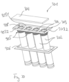
- the feedthrough also has a base body on which the casting body sits, which is therefore arranged below the casting body.
- the base body can, for example, increase the stability of the feedthrough before/during casting or also serve to fix different components of the feedthrough in relation to one another. If, for example, several jacket pipes are provided, the base body can hold them together.
- a metallic base body is also conceivable; a plastic part, in particular made of a hard plastic, in particular an injection-molded part, is preferred.
- the casting body and the base body are assembled; in the vertical direction, the two can be held together in a form-fitting and/or force-fitting manner.
- an adhesive connection is possible (also in combination with a form-fitting connection), which can also create a certain degree of sealing (e.g. against the penetration of concrete milk).
- the base body itself forms the jacket tube or a section of it, i.e. is formed with a hose-like extension.
- the base body and the jacket tube are assembled parts.
- the jacket tube could also be held in the casting body itself, for example in a form-fitting manner (e.g. locked in place) or glued in.
- the base body serves for relative fixation, namely the casting body is placed on top and the jacket tube is attached from below, in particular pushed in through a bottom part of the base body.
- the jacket tube is preferably held in a form-fitting manner (locked in place) on the base body.
- the base body preferably forms a cavity that is open at the top, i.e. it has a base part and a side wall.
- the jacket pipe also preferably extends from below into this cavity.
- the upper end of the jacket pipe is above the base part, but preferably below the upper end of the side wall. The jacket pipe can thus be reliably inserted and is easily accessible, but on the other hand does not have to be cut to length even if the entire casting body is removed in exceptional cases.
- the side wall of the base body preferably forms a collar that encloses the potting body on the outside.
- the side wall is preferably formed with a step on which the potting body sits.
- the collar is then arranged on this step, enclosing it on the outside.
- An internal volume (cavity) of the feedthrough is then limited in a lower area solely by the side wall and in an upper area solely by the potting body; the step marks the transition.
- the potting body could also sit on a bottom part of the base body, for example, and the entire side wall could therefore represent a collar.
- the collar is advantageous in terms of stability, as it holds the potting body in position when positioning the feedthrough and then also during potting.
- a base body with a side wall is cast into a base plate in a preferred embodiment in such a way that its upper edge is at the upper end of the side wall.
- the upper end of the side wall should be offset vertically by no more than 5 cm, 4 cm, 3 cm or 2 cm from the upper edge, for example; the upper end is particularly preferably at the level of the upper edge, i.e. flush, within the scope of technically usual accuracy.
- the mounting attachment is or is screwed to the base body in the mounting position. It can be brought into the mounting position by screwing it, preferably in contact with the surface of the floor element.
- a thread can be cut into the base body, for example, or a corresponding insert can be inserted or injected, such as a threaded sleeve or nut.
- the feedthrough has a mounting device which serves for positioning or alignment before casting.
- the mounting device can, for example, comprise a ground spike or stand, which is placed in the excavated trench.
- the casing pipe and the casting body are suspended from it, preferably via another, height-adjustable support section.
- the feedthrough is placed at the desired height before pouring, using the top edge of the floor slab as a reference.
- its thickness or height and thus the position of the top edge is usually known, in contrast to the thickness of the floor structure that will later be built on top of it.
- its upper end is preferably placed at the height of the top edge of the floor slab (flush).
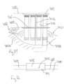
- the casting material of the floor slab then encloses the base body including the side wall, but not the casting body. The casting body is then enclosed only by the screed or the rest of the floor structure, which can represent a lower mechanical load.
- a flange is provided on the base body of the feedthrough, which lies flush with the upper edge of the floor slab after being poured into the floor slab.
- the flange can therefore also be used, for example, to adjust the feedthrough to the correct height.
- the flange can protrude outwards from the base body by at least 2 cm, preferably at least 3 cm or 4 cm (possible upper limits can be, for example, a maximum of 30 cm, 20 cm or 15 cm).
- a surface seal is preferably worked onto the flange, i.e. a surface seal on the floor slab. This is preferably a vapor barrier, which is laid out on the floor slab in the form of a film, for example. This film can then be attached to the flange, preferably glued.
- the passage has a plurality of jacket pipes, i.e. at least 2, preferably at least 3. Possible upper limits (independently of this) are, for example, a maximum of 6 or 5 jacket pipes, particularly preferably 4 jacket pipes are provided. Each section is then assigned its own jacket pipe, The electrical/data sections can also be combined.
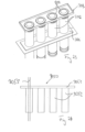
- the jacket pipes are or are assembled with the base body of the feedthrough (see above). The base body holds the jacket pipes in a relative position to one another, and these can in particular be pushed into its base part from below.
- the feedthrough additionally has a holding part which is arranged beneath the base body and holds the jacket pipes in a relative position to one another.
- the installation device can then be attached, for example, to the holding part and/or the base body, preferably to both.
- a holding part made of metal is also conceivable, for example made of bent sheet metal strips into which the jacket pipes can be clipped.
- the holding part is made of a plastic material. Regardless of the material, it preferably has a plate shape (flat extension in a horizontal direction), and the plate is penetrated by through holes for the jacket pipes. The jacket pipes can be pushed into the plate, but this can also be split and assembled around the jacket pipes.
- the holding part is sealed against the casing pipes, for example with sealing rings pushed onto the casing pipes or a seal molded onto the holding part.
- the holding part can then advantageously also serve as a water barrier flange.
- the leadthrough with the holding part is adjusted so that the holding part sits on a fill before the base plate is cast.
- a surface seal is then preferably applied to the fill or blind layer, i.e. underneath the subsequently cast base plate, and worked onto the holding part.
- a plastic film is preferred as a surface seal, which is further preferably provided with a metal additive, such as aluminum.
- This arrangement can represent a radon seal (radon gas could due to the chimney effect, the air is sucked from the ground through the building), whereby the work on the holding part in the area around the casing pipes ensures a reliable connection.
- the holding part makes the work much easier, especially when there are a large number of casing pipes.
- the holding part is preferably designed as a plate for this purpose, and it is particularly preferred that it has a flange that protrudes outwards.
- the casting body is provided with a brace on the inside. This stabilizes the outer wall areas of the casting body that are opposite one another. However, the brace leaves passages that are vertically aligned with the jacket pipes. If the mounting attachment is placed with pipe sockets, the brace in the lower section of the casting body does not have to be removed first.
- the feedthrough is preferably installed in a floor element that includes a floor slab and a floor structure.
- the floor slab is poured on the ground, usually on a special underlay or fill, in particular on a blind layer. Concrete is preferred as a casting material.
- the floor structure is then built on the floor slab, which defines the subfloor and functionally forms the foundation of the building.
- the latter can in particular include a screed layer, optionally further layers such as thermal insulation and/or underfloor heating, typically a floor covering forms the upper finish (for example tiles etc.).
- the feedthrough is cast into the floor slab and usually into a screed layer, the other layers are usually not cast layers. If we talk about casting into the floor element, this means casting into at least one layer of it (the floor slab).
- a method for producing a floor element with a floor plate and floor structure thereon is to be disclosed, which results in the features of the use according to claim 1, preferably in combination with one or more of the dependent claims.
- the subject matter of the disclosure is also the use of a feedthrough for casting into a floor slab and passing through a line, according to the "spacer" variant discussed below.
- the feedthrough in question can be used as a building entry point to lay the cable through the floor slab into the building in the case of a building without a basement.
- the feedthrough is first positioned on the construction site and aligned using a batter board, for example. When the floor slab is poured, it is cast into it and keeps a passage free for the cable or cables.
- the present invention is based on the technical problem of specifying a particularly advantageous implementation as the subject of such a use.
- the feedthrough has a casing pipe and a base body that is arranged at the upper end of the casing pipe. With a base part and a side wall, the base body defines a cavity at the upper end of the casing pipe. This arrangement is then cast into the base plate in such a way that the side wall of the base body has a maximum overhang of 5 cm relative to an upper edge of the base plate, i.e. it either only protrudes slightly or is flush with or below the upper edge.
- a floor structure is then created on the floor slab, typically a layer of screed is poured on, often in conjunction with an insulation layer underneath (between the floor slab and the screed) and/or a floor covering on top.
- the height of the floor structure that will later be built on top is usually not yet known, so it is not possible to simply place the casing pipe at a height when pouring the floor slab that its upper end matches the finished floor structure.
- One approach could be to provide the casing pipe or a box arranged above it (which keeps a hollow space free at the end of the casing pipe) with such an excess that there is always an overhang above the upper edge of the finished floor. This overhang must then be cut to length or removed, which is a lot of work for a fitter, but not removing it can pose a safety risk (see below).
- the present approach is to cast the base body, with which the cavity above the jacket pipe is kept free and thus accessible, into the base plate with a (small) overhang if necessary, but to keep this overhang so small that the upper end of the base body is then in any case within the floor structure. Due to the slight overhang of, in increasing order of preference, no more than 5 cm, 4 cm, 3 cm, 2 cm or 1 cm, the base body then does not protrude from the floor structure, and therefore no shortening is necessary.
- the cavity above the jacket pipe is kept separately free, e.g. with an inserted or attached formwork element (see below in detail for various options).
- a line can then be laid through the jacket pipe through the floor slab; for this purpose, an assembly attachment with a pipe socket is or will be attached to the jacket pipe.
- This pipe socket extends the jacket pipe upwards, in particular towards the upper edge of the floor structure.
- the assembly attachment preferably has a flange plate from which the pipe socket extends downwards, see below in detail.
- the mounting attachment can be positioned relatively close to or flush with the upper edge of the floor structure. If a fire breaks out in the building, this can delay or prevent a fire from breaking through to the gas line, for example. With a mounting attachment that is flush with the floor structure, the casing pipe underneath can be shielded to some extent from the inside of the building. By way of comparison, if a box that protrudes from the floor structure and needs to be shortened (see above) is not shortened properly by a fitter, the protruding side wall would quickly melt away in the event of a fire, thus opening up a "channel" to the gas line (e.g. in the case of plastic material, which would be useful because of the shortening).
- the base body in the present case has a comparatively low height overall, for example of no more than 10 cm, 8 cm, 6 cm, 5 cm or 4 cm, with possible (independent) lower limits of, for example, at least 1 cm or 2 cm.
- the height of the side wall is therefore preferably in a corresponding range.
- This line could be a gas line, for example, but the problem of "breakthrough” described can also arise in the case of another branch (e.g. electrical or data), as there may be leaking gas in the jacket pipe of this branch due to an incident or damage on the outside of the building.
- the duct is preferably designed to route several lines through, for which purpose it preferably has several jacket pipes (see below in detail). These can then be used for the individual branches (water, gas, electrical or data, etc.).
- the protective function described can be particularly effective here.
- the mounting attachment can preferably have a flange plate, i.e. a flange that protrudes outwards, particularly preferably a completely circumferential flange that has a lateral overlap with the surface of the floor structure in the mounting position (a vertical projection of the flange lies at least partially in the surface of the floor structure); preferably the flange sits on the surface of the floor structure.
- the flange plate is preferably made of plastic, in particular fiber-reinforced plastic, such as glass fiber-reinforced polyamide.
- the mounting attachment can also serve in particular as a pull-out protection, i.e.
- a through hole is preferably provided in the flange plate through which the installed line then extends into the building.
- the through hole is aligned with the pipe socket at the bottom.
- the line is then preferably sealed against the mounting attachment with a sealing element, e.g. made of an elastomer material.
- a sealing element e.g. made of an elastomer material.
- the jacket pipe serves as a casing or empty pipe for the actual line, which is usually only laid after the floor slab has been poured or the floor structure has been created.
- the jacket pipe forms or is part of a protective pipe system that extends from the building to, for example, a street-side connection point (supply line).
- This protective pipe system is then laid at least in part, preferably in its entirety (up to the connection point), before the floor slab is poured.
- the trench can then preferably already be filled again (also between the building and the connection point).
- the actual line for example a pipe (gas, water or district heating) or a cable (electrical or data) can then be laid later, namely pushed through the protective pipe system from inside the building or from the connection point.
- the seal between the line and the mounting attachment mentioned above can then be created.
- top/"bottom refers to the vertical direction, i.e. to the situation in which the feedthrough is installed.
- Information such as “side” or “inside”/"outside” refers, unless expressly stated otherwise, to the directions perpendicular to a vertical axis of the feedthrough and pointing away from it (these are horizontal).
- the side wall preferably extends all the way around and is closed in on itself, thus enclosing the cavity on all sides. In the vertical Viewed in the vertical direction, it can have a round, particularly circular, or an angular shape (also with rounded corners).
- the casing pipes can be arranged flat in the vertical direction (e.g. at the corners of a square) or preferably in a row next to each other.
- spacer in which the side wall protrudes beyond the upper edge of the floor slab and a formwork element is attached to it, which keeps the cavity at the upper end of the casing pipe free when the floor structure is created.
- the base body is cast in such a way that the side wall protrudes from the upper edge of the floor slab, for example by at least 1 cm.
- the side wall can then be used to attach a formwork element, in particular the outer wall surface of the side wall is also available for this purpose.
- the formwork element then keeps the cavity above the casing pipe free, especially when pouring the screed.
- the floor slab is generally poured on the ground, typically on a fill, especially on a sub-base layer. It is usually poured from concrete, and functionally it forms the foundation of the building.
- the floor structure is later built on top of this, e.g. the screed is poured on (if necessary on an insulating layer as part of the floor structure), on which a floor covering can be applied.
- the formwork element is a strip which is glued to a wall surface of the side wall and/or to the bottom part of the base body.
- a strip is used as the formwork element, for example made of a foamed plastic material. This is then glued to the outer wall surface or the inner wall surface of the side wall, for example with an adhesive tape. Additionally or alternatively, the strip can also be glued to the bottom part of the base body.
- the base body is cast flush with the upper edge of the floor slab. This can, for example, simplify the removal or smoothing of the casting material, usually concrete.
- the side wall can be used to attach a formwork element when creating the floor structure; for example, a strip can be glued to the inner wall surface.
- a molded body can also be inserted into the base body that protrudes from the upper edge of the floor slab. The side wall can give such a molded body a defined position and prevent it from slipping.
- the mounting attachment whose pipe socket is attached to the jacket pipe when the feedthrough is already installed in the floor structure, can also be cast in together with the base body.
- the pipe socket would then be, for example, in the casing pipe is pushed in, preferably far enough that a flange plate of the mounting attachment is arranged in the cavity of the base body, preferably completely accommodated therein.
- the latter can be advantageous in that the base body including the flange plate can then be cast flush with the floor in the base plate.
- the mounting attachment is then pulled out a little bit upwards (regardless of whether it was previously installed flush with the floor or not). At this point, the height of the floor structure is usually known and the mounting attachment can be set to this height.
- the underside of the flange plate can be at this height or even a little higher (e.g. by a maximum of 10 cm, 5 cm, 4 cm, 3 cm, 2 cm or 1 cm), and can then be moved downwards into the system after the floor structure is completed.
- the base body and the jacket pipe are cast in the floor slab without the mounting attachment, and the mounting attachment is then only attached later.
- the base body and the jacket pipe form or are part of a rough component that is structurally integrated when the floor slab is cast.
- the mounting attachment is then only attached later, when the casting material of the floor slab has hardened.
- the mounting attachment can be attached before the floor structure is created (in particular, the pipe socket can be pushed into the jacket pipe).
- a flange plate can be positioned at the height of the upper edge of the floor structure that has been created or even above it, see also the comments and centimeter specifications in the previous paragraph. With this procedure, the cavity above the The casing pipe is kept clear of the pipe socket of the mounting attachment when constructing the floor structure.
- the assembly attachment can also be attached after the finished floor has been created.
- the cavity above the casing pipe is kept free for this purpose, for example by a formwork element mentioned above or a cover part discussed below.
- the pipe socket (of the assembly attachment) can also be pushed onto the casing pipe during the "attachment” process; the attachment is preferably to be read as a pushing in (the pushed-in pipe socket can advantageously also extend downwards in the casing pipe beyond the base body).
- the feedthrough has a cover element which covers the cavity formed by the base body at the top when poured into the base plate.
- a cover element of the feedthrough covers the cavity formed by the base body at the top when the base body is cast into the base plate. If the mounting attachment is also cast in, its flange plate can form this cover element.
- spacer in which at least a section of the cover element extends above the side wall of the base body, this section being used as formwork when creating the floor structure.
- the cover element is cast flush into the base plate, so that the top of the cover element is flush with the top edge of the base plate.
- the cover element can also be formed in one piece with the base body; it could then be knocked out after casting, for example with a hammer. This could be supported by a predetermined breaking point.
- the cover element is a multi-piece cover part for the base body (base body and cover part are two separate parts).
- the cover part is then removed from the base body after the base plate has been cast, sometimes only after the floor structure has been created.
- the cover part can also be a lid placed on the base body, for example.
- cover element is a multi-piece cover part to the base body, which is removed from or out of the base body after the floor structure has been created.
- the cover element is a molded body arranged in the cavity of the base body.
- the cover part can fill the cavity, for example, to at least 50%, 60% or 70%, and in any case in an upper section thereof it preferably borders all the way around the side wall of the base body (on its inner wall surface).
- the cover part can also be the flange plate of the mounting attachment, but on the other hand A separate cover part may also be preferred (which is then completely removed from the feedthrough and does not remain on the fully assembled arrangement).
- a preferred embodiment is directed at a separate cover part, according to which the cover part arranged in the cavity of the base body protrudes upwards beyond its side wall.
- the protruding section can then be used as formwork when creating the floor structure, i.e. to keep the cavity above the casing pipe free of e.g. the screed.
- the cover part is then removed after the floor structure has been created and the assembly attachment can be placed.
- the cover part arranged in the hollow body is made of a foamed plastic material, for example foamed polystyrene or polypropylene. Extruded polypropylene may be of particular interest. These options relate to both flush installation with the upper edge of the floor panel and installation with an overhang. In particular, two cover parts can also be provided, with one of a lower height being cast flush into the floor panel and then replaced by a cover part of a higher height for creating the floor structure.
- the cover part arranged in the cavity sits on the upper end of the casing pipe.
- the cover part and the casing pipe are sealed against each other with a seal. This can, for example, prevent dirt from entering the casing pipe during the shell construction phase (e.g. via rainwater, which washes in dirt from the surface of the floor element or floor structure) or can also provide protection against creeping gas during the shell construction phase.
- the seal is preferably arranged between an upper end face of the casing pipe and the cover part. It is preferably made of an elastomer material.
- the “elastomer material” is generally a plastic with elastic properties. Its Shore hardness (Shore A) can be, for example, a maximum of 90 Shore, 80 Shore, 75 Shore or 70 Shore and (independently of this) a minimum of 20 Shore, 25 Shore, 30 Shore, 35 Shore or 40 Shore. It can be, for example, a rubber material, preferably a synthetic rubber, such as EPDM (ethylene propylene diene, M group). However, it can also be, for example, a thermoplastic elastomer (TPE) or a silicone-based material, such as silicone rubber or silicone elastomer.
- TPE thermoplastic elastomer
- silicone-based material such as silicone rubber or silicone elastomer.
- the seal is attached or molded onto the cover part and is then removed together with the cover part.
- the seal remains on the casing pipe when the cover part is removed from the base body.
- This variant concerns the subsequently attached assembly attachment, which is therefore only attached to the duct after the base plate has been cast and, if necessary, the floor structure has been created.
- the seal which previously sealed the cover part and the casing pipe against each other, then seals the latter against the pipe socket of the assembly attachment. The same seal can therefore advantageously be used twice.
- seal has a sealing lip which protrudes inwards or outwards in the unloaded state, which is turned downwards when the pipe socket is attached and is positioned between the pipe socket and the casing pipe.
- the seal has a sealing lip that protrudes outwards (pipe socket is pushed on) or preferably inwards (pipe socket is pushed in).
- the sealing lip therefore has a radial extension when viewed in an axial section.
- sealing lip is arranged between the jacket pipe and the pipe socket, movement or deformation back to its original state is blocked by the pipes, so that the sealing lip reliably remains in the pulled-down state between the pipes, for example even in the event of a pressure event (overpressure) in the pipe system.
- the sealing lip can be pushed out less easily, for example in comparison to a sealing ring (O-ring) arranged between the pipes.
- O-ring sealing ring
- seal has a sealing lip which protrudes inwards or outwards in the unloaded state and which extends obliquely upwards towards its free end in the unloaded state.
- the seal has a sealing lip that extends diagonally upwards towards its free end when not under load.
- the "unloaded state” refers to a situation in which the seal is arranged on the casing pipe, but neither the pipe socket nor the cover part is attached.
- the extension of the sealing lip diagonally upwards can be advantageous, for example, in that it then reliably seals against the cover part, and the cover part presses the sealing lip downwards a little. This is preferably the same sealing lip that is then inserted between the casing pipe and the pipe socket.
- the extension diagonally upwards can also be advantageous with regard to the subsequent seal between the pipes, namely by further increasing the "self-locking" described above when it is pushed downwards.
- the extension "oblique” can mean, for example, an angle of at least 30°, 45°, 60° or 70° and (independently of this) no more than 85° or 80° (the smaller of two angles that the sealing lip forms with the pipe axis is considered in each case).
- the sealing lip is not deflected too much from an extension perpendicular to the pipe axis, for example by no more than 40°, 30° or 20° (with possible lower limits of at least 5° or 10°).
- the seal that remains on the casing pipe can be molded onto the casing pipe or manufactured as a separately manufactured part be assembled with it.
- the molding can be done, for example, in the course of a 2K injection molding process. If the two parts are assembled as previously manufactured separately, the seal can preferably be held axially in a form-fitting manner on the casing tube, for example a section of the seal can sit in a groove on the casing tube, preferably a groove in the outer wall surface of the casing tube.
- spacer in which a flange is provided on the base body, which lies flush with the upper edge of the floor slab after the base body has been poured into the floor slab, wherein a surface seal on the floor slab is worked onto the flange before the floor structure is created.
- a flange is provided on the base body of the feedthrough, which lies flush with the upper edge of the floor slab after being poured into the floor slab.
- the flange can therefore also be used, for example, to adjust the feedthrough to the correct height.
- the flange can protrude outwards from the base body by at least 2 cm, preferably at least 3 cm or 4 cm (possible upper limits can be, for example, a maximum of 30 cm, 20 cm or 15 cm).
- a surface seal is preferably worked onto the flange, i.e. a surface seal on the floor slab. This is preferably a vapor barrier, which is laid out on the floor slab in the form of a film, for example. This film can then be attached to the flange, preferably glued.
- a flange on the feedthrough which lies flush with the upper edge of the floor slab after it has been cast into the floor slab, can also be of interest independently of the side wall, which protrudes by a maximum of 5 cm according to the main claim, and should be disclosed accordingly.
- the flange can therefore be arranged, for example, on a base body, the side wall of which protrudes further after it has been cast into the floor slab, in particular also over the floor structure that is created later.
- the flange does not necessarily have to be arranged on a hollow body-shaped base body; it can also be a solid body made of foamed plastic material with a flange, for example made of extruded polystyrene or polypropylene.
- a flange plate could be arranged on the jacket pipe(s) (the pipe(s) could be inserted into this), with this arrangement then being cast in such a way that the flange or flange plate is flush with the upper edge of the base plate.
- the feedthrough generally has a plurality of jacket pipes, i.e. at least 2, preferably at least 3. Possible upper limits (independent of this) are, for example, a maximum of 6 or 5 jacket pipes, with 4 jacket pipes being particularly preferred.
- Each section is then assigned its own jacket pipe, whereby the electrical/data sections can also be combined.
- the jacket pipes are or are assembled with the base body of the feedthrough (see also above). The base body holds the jacket pipes in a relative position to one another, and these can in particular be pushed onto or into its base part from below.
- the feedthrough additionally has a holding part which is arranged beneath the base body and holds the jacket pipes in a relative position to one another.
- a setting device can then be attached, for example, to the holding part and/or the base body, preferably to both.
- a holding part made of metal is also conceivable, for example made of bent sheet metal strips into which the jacket pipes can be clipped.
- the holding part is made of a plastic material. Regardless of the material, it preferably has a plate shape (flat extension in a horizontal direction), and the plate is penetrated by through holes for the jacket pipes. The jacket pipes can be pushed into the plate, but this can also be split and assembled around the jacket pipes.
- the feedthrough has a plurality of jacket tubes which are arranged on the base body, wherein a holding part is additionally arranged below the base body, which holds the jacket tubes in a relative position to one another.
- the holding part is sealed against the casing pipes, for example with sealing rings pushed onto the casing pipes or a seal molded onto the holding part.
- the holding part can then advantageously also serve as a water barrier flange.
- the feedthrough with the holding part is adjusted so that the holding part sits on a fill before the base plate is poured.
- a surface seal is then preferably applied to the fill or blind layer, i.e. below the subsequently poured base plate, and worked onto the holding part.
- a plastic film is preferred as the surface seal, which is more preferably provided with a metal additive, such as aluminum.
- This arrangement can represent a radon seal (radon gas could be sucked through the building from the ground due to the chimney effect), whereby working onto the holding part in the area around the jacket pipes ensures a reliable connection.
- the holding part makes work much easier, especially when there are a large number of jacket pipes.
- the holding part is preferably designed as a plate for this purpose, and it is particularly preferred that it has a flange that protrudes outwards.
- spacer in which the holding part rests on a fill on the ground before the base plate is poured, wherein a surface seal on the fill is worked onto the holding part before the base plate is poured.
- the feedthrough preferably has a mounting device that is used for positioning or aligning before pouring.
- the mounting device can, for example, comprise a ground spike or stand that is placed in the excavated trench.
- the casing pipe and the casting body are suspended from this, preferably via another, height-adjustable stand part.
- the feedthrough is placed at the desired height before pouring, using the upper edge of the base plate as a reference. Before pouring the base plate, its thickness or height and thus the position of the upper edge is usually known, in contrast to the thickness of the floor structure that will later be built on top of it.
- a method for producing a floor panel with a floor structure thereon is to be disclosed, which results from the features of the use according to the first aspect of "spacer”, preferably in combination with one or more of the dependent aspects.
- the disclosure also relates to the use of a feedthrough for casting into a floor slab and passing through a line, according to the following variant "telescopic frame".
- the feedthrough in question can be used as a building feedthrough in order to lay the cable through the floor slab into the building in the case of a building without a basement.
- the feedthrough is initially installed on positioned on the construction site and aligned using a batter board, for example. When the base plate is poured, it is cast into it and leaves a passage for the pipe or pipes.
- the present invention is based on the technical problem of specifying a particularly advantageous implementation as the subject of such a use.
- the duct has a casing pipe and a base body, which is arranged at an upper end of the casing pipe in relation to a vertical axis.
- the base body and the casing pipe are cast into the floor slab, then a floor structure is created on the floor slab, typically a screed layer is poured on, often in conjunction with an insulation layer. underneath (between the floor slab and the screed) and/or a floor covering on top.
- the base body cast into the floor slab has a first side wall, against which the casting material of the floor slab adheres when poured.
- the base body also has a second side wall, which is arranged within the first side wall.
- the latter refers to directions perpendicular to the vertical axis, from the vertical axis outwards the first side wall follows the second (correspondingly the second is within the first).
- the casting material of the floor slab adheres to the outer (first) side wall, which keeps a hollow space free at the upper end of the casing pipe.
- the second side wall is then moved upwards so that at least a section of the second side wall extends above the first side wall. This extends the hollow space upwards, so to speak, and the second side wall keeps it free when the floor structure is being created.
- the screed can, for example, adhere to the second side wall.
- the base body therefore has several side walls and is extended upwards during installation by moving the side wall or walls. This can be advantageous, for example, because when the base slab is poured, the height of the floor structure that will later be built on top of it is often not yet known. It is therefore not possible to simply place the casing pipe or the first side wall of the base body at such a height ab initio that the upper end then matches the finished floor structure.
- the base slab is poured, however, its height is known, so the base body can be adjusted so that the upper end of the outer side wall is, for example, flush with the upper edge of the base slab or even protrudes slightly.
- the floor structure is then created later, its height is also known and the height of the base body can be adjusted accordingly.
- the base body then keeps a cavity above the casing pipe free up to the upper edge of the floor structure.
- the casing pipe can then a cable is to be laid through the floor slab.
- an installation attachment with a pipe socket is or will be attached to the casing pipe.
- This pipe socket extends the casing pipe to the upper edge of the floor structure.
- the installation attachment preferably has a flange plate from which the pipe socket extends downwards.
- the height of the base body can be adjusted in particular so that it does not protrude from the floor structure. Consequently, the mounting attachment can be positioned relatively close to or flush with the upper edge of the floor structure. If a fire breaks out in a building, this can delay or prevent a breakthrough to the gas line, for example. With a mounting attachment that is flush with the floor structure, the casing pipe underneath can be shielded to some extent from the inside of the building. By way of comparison, if a base body that cannot be adjusted in height were to protrude from the floor structure, the protruding side wall could quickly melt away in the event of a fire, thus opening up a "channel" to the gas line (e.g. in the case of plastic material, which is preferred).
- This line could be a gas line, for example, but the problem of "breakthrough" described can also arise in the case of another branch (e.g. electrical or data), as there may be leaking gas in the jacket pipe of this branch due to an incident or damage on the outside of the building.
- another branch e.g. electrical or data
- the feedthrough is designed to allow several cables to pass through, for which purpose it preferably has several jacket pipes (see below in detail). These can then be used for the individual sectors (water, gas, electricity or data, etc.).
- the protective function described can be particularly effective here.
- the mounting attachment can preferably have a flange plate, i.e. a flange that protrudes outwards, particularly preferably a completely circumferential flange that has a lateral overlap with the surface of the floor structure in the mounting position (a vertical projection of the flange lies at least partially in the surface of the floor structure); the flange preferably sits on the surface of the floor structure.
- the flange plate is preferably made of plastic, in particular fiber-reinforced plastic, such as glass fiber-reinforced polyamide.
- the mounting attachment can also serve in particular as a pull-out protection, i.e.
- a through hole is preferably provided in the flange plate through which the installed line then extends into the building.
- the through hole is aligned with the pipe socket at the bottom.
- the line is then preferably sealed against the mounting attachment with a sealing element, e.g. made of an elastomer material.
- a sealing element e.g. made of an elastomer material.
- the jacket pipe serves as a casing or empty pipe for the actual line, which is usually only laid after the floor slab has been poured or the floor structure has been created.
- the jacket pipe forms or is part of a protective pipe system that extends from the building to, for example, a street-side connection point (supply line).
- This protective pipe system is then laid at least in part, preferably in its entirety (up to the connection point), before the floor slab is poured.
- the trench can then preferably already be filled again (also between the building and the connection point).
- the actual line for example a pipe (gas, water or district heating) or a cable (electrical or data) can then be laid later, namely pushed through the protective pipe system from inside the building or from the connection point.
- the seal between the line and the mounting attachment mentioned above can then be created.
- top/"bottom refers to the vertical direction, i.e. to the situation in which the feedthrough is installed.
- Information such as “side” or “inside”/"outside” refers, unless expressly stated otherwise, to the directions perpendicular to a vertical axis of the feedthrough and pointing away from it (these are horizontal).
- the vertical axis is vertical and central in the feedthrough, i.e. it passes through the geometric center of gravity of an area kept free by the first side wall on the surface of the base plate (this kept free area lies in the same plane as the surface of the base plate).
- the side wall or walls preferably extend all the way around, enclosing the cavity on all sides.
- the jacket pipes can be arranged flat (e.g. at the corners of a square) or preferably in a row next to each other.
- the second side wall arranged inside when the base body is cast can generally be made of an elastomer material and can be turned out upwards.
- the second side wall could be fixed in position to the first side wall at its upper end when turned in, for example by joining or even manufactured in one piece by 2K injection molding.
- the opposite side wall is then lower end is brought upwards (the inner wall surface when folded in is on the outside when folded out).
- a foldable side wall made of an elastomer material can sometimes be less stable than the first side wall, which is preferably made of a hard plastic.
- the load when creating the floor structure (the screed) is generally lower than when pouring the floor slab.
- the floor slab is generally poured on the ground, typically on a fill, especially on a sub-base layer. It is usually poured from concrete, and functionally it forms the foundation of the building.
- the floor structure is later built on top of this, e.g. the screed is poured on (possibly on an insulating layer as part of the floor structure), and a floor covering can be applied on top of this.
- telescopic frame in which the second side wall is arranged telescopically extendable within the first side wall and is pulled out upwards after the base plate has been poured.
- the second side wall is arranged in a telescopically extendable manner within the first side wall.
- the side walls can then also be rigid, for example made of a hard plastic.
- the second side wall is pulled out upwards. Typically, even in the extended state, it is still arranged perpendicular to the vertical axis within the first side wall, but it is offset axially upwards.
- the first side wall preferably encloses the second side wall outwards over its entire axial length.
- the telescopic mechanism can be used to set several different heights by pulling out the second side wall to different extents. This means that the base body can be adjusted without subsequent shortening (overhang, which is then removed) flush with the upper edge of the floor structure.
- the telescopic mechanism also enables the use of rigid side walls, which can be advantageous in terms of stability, for example.
- the telescopic extension of the second side wall is limited upwards by a stop.
- the first and second side walls are thus held together in an axially positive manner in a maximally extended position, for example by an outward-facing projection at the lower end of the inner side wall, which rests against an inward-facing projection at the upper end of the outer side wall.
- the axially positive cohesion can, for example, simplify handling on the construction site and help prevent assembly errors.
- the feedthrough has a locking means which holds the second side wall in an upwardly extended position.
- a locking mechanism wherein, for example, a locking rail specifies a plurality of locking positions in which a locking means (e.g. projection or spring) comes to lie one after the other when pulled out.
- the locking means can be a lockable telescopic rod, the telescopic rod parts of which can be extended axially in a release position.
- the telescopic rod parts By turning the telescopic rod parts relative to each other (around a longitudinal axis of the telescopic rod) they can be brought into a locking position in which the axial offset is blocked.
- the latter can be done in a form-fitting or force-fitting manner, for example by spreading a conical shape with the rotary movement.
- a screw connection is also conceivable as a locking device.
- a screw can press outwards through the inner side wall (at its lower end) against the outer side wall.
- a screw connection is also possible which supports the inner side wall relative to a base part of the base body.
- the locking device is advantageously arranged within the outer (first) side wall. This means that it sits protected inside when it is poured into the base plate. If the floor structure is created later, the locking device holds the side walls in the extended position, whereby the arrangement within the base body can prevent the locking device from being accidentally released, for example.
- telescopic frame in which the passage has a clamping spindle and the second side wall is moved upwards by rotating the clamping spindle, wherein the clamping spindle is arranged perpendicular to the vertical axis within the first side wall.
- the passage has a clamping spindle and the side wall or walls can be pulled out upwards by turning the clamping spindle.
- the clamping spindle a head of which for attaching a tool
- the spindle is supported axially between the outer (first) side wall and the inner (second) or innermost side wall, and when it is turned it pushes the side walls apart axially.
- the clamping spindle is within the first side wall, preferably within all side walls, i.e. like the locking device discussed above, inside the base body.
- the clamping spindle can be combined with a locking mechanism or a lockable telescopic rod, for example, but it can also be used for extension and at the same time represent the only locking device in itself.
- telescopic frame in which the base body has a third side wall which, when the base body and the casing tube are cast into the base plate, is arranged perpendicular to the vertical axis within the first and second side walls.
- the base body additionally has a third side wall, which is arranged within the first and second side walls.
- the third side wall is then guided on the second side wall so that it can be extended axially, preferably limited by a stop (see the above comments regarding the stop between the first and second side walls).
- the first side wall encloses the second and third side walls on the outside (preferably over their entire axial length).
- several side walls are arranged within the first side wall, which can increase stability when pouring into the base plate.
- each of the side walls can be made smaller in height without limiting the total height possible in the extended state, which results in a compact base body when poured into the base plate.
- a corresponding base body then has at least three side walls and, for example, no more than five or four side walls, with exactly three side walls being preferred.
- telescopic frame in which the side walls each have a maximum height of 30 cm.
- the side walls each have a height of at most 30 cm, with a maximum of 25 cm being more preferred. Possible lower limits are, for example, at least 15 cm or 20 cm.
- the inner side wall or walls have a slightly lower height than the first side wall, for example by at least 5% or 10% (with possible upper limits of, for example, at most 30% or 20%). This reflects the idea already mentioned above that the outer side wall preferably encloses the inner side wall over its entire height when poured into the base plate.
- the first side wall is preferably formed integrally with a base part, so that the jacket pipe is preferably assembled.
- the jacket pipe can generally also be pushed on from below, preferably it is pushed in from below through the base part with the first side wall.
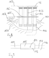
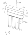
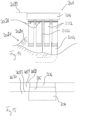
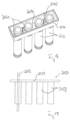
- the seals 41 are placed between the respective pipe socket 52 and the respective jacket pipe 2, see also the explanations for Figure 19 .
- the base body is cast flush with the upper edge of the base plate, i.e. the upper edge of the outer first side wall is flush with the upper edge of the base plate.
- Flush installation can simplify the casting, for example the removal or smoothing of the casting material, usually concrete.
- the base plate is placed directly on poured from the ground, usually on a embankment.
- the casting material (the concrete) then encloses the base body laterally and preferably also downwards.
- the latter can be advantageous in that a multi-web seal arranged underneath the base body, on the outside of the casing pipe, can then also be reliably enclosed by the concrete and block creepage paths for moisture upwards.
- telescopic frame in which the feedthrough has a cover which closes the base body at the top when it is poured into the base plate.
- the feedthrough has a cover that closes the base body at the top when it is poured into the base plate.
- the feedthrough can also be poured in with the mounting attachment already attached, in which case the flange plate of the mounting attachment forms the cover.
- a cover can also be provided that is removed or taken off after pouring into the base plate or after the floor structure has been created. When pouring into the base plate, the cover is preferably flush with an upper side edge of the outer (first) side wall.
- telescopic frame in which the lid is arranged in a fixed position on that of the side walls which is arranged at an innermost position perpendicular to the vertical axis.
- the lid is provided in a fixed position on the innermost side wall, i.e. on the second in the case of exactly two side walls or on the third in the case of exactly three side walls.
- the lid arranged on the innermost side wall can generally also be formed integrally therewith, for example by injection molding, and then be knocked out, for example.
- the lid and the side wall are assembled, particularly preferably they are locked together. This can simplify the removal of the lid.
- a preferred embodiment can be such that the locking mechanism is accessible from above through the lid, i.e. can be easily released by applying a tool, e.g. a screwdriver.
- the mounting attachment the pipe socket of which sits on the casing pipe when the feedthrough is fully installed in the floor structure, can be cast into the floor slab together with the base body.
- the pipe socket is then pushed into the casing pipe, for example, and the flange plate of the mounting attachment preferably forms a cover as discussed above, which is more preferably flush with the upper edge of the first side wall when cast in.
- the mounting attachment is then pulled out a little way upwards.
- the height of the floor structure is usually known, and the mounting attachment can be set to this height.
- the underside of the flange plate can be at this height or higher (e.g. by a maximum of 10 cm, 5 cm, 4 cm, 3 cm, 2 cm or 1 cm), and can then be moved downwards into the system after the floor structure is completed.
- the base body and the casing pipe are cast in the base plate without the mounting attachment, the mounting attachment is then only attached subsequently.
- the pipe socket (of the mounting attachment) can also be pushed onto the casing pipe during the "attachment" process, preferably the attachment is to be read as an insertion (the inserted pipe socket can be in the casing pipe advantageously also extend downwards beyond the base body).
- the base body and the casing pipe form or are part of a rough component that is structurally integrated when the floor slab is cast.
- the assembly attachment is then only attached subsequently when the casting material of the floor slab has hardened.
- the assembly attachment can be attached before the floor structure is created (in particular the pipe socket can be pushed into the casing pipe).
- a flange plate can be positioned at the level of the upper edge of the floor structure that is then created or even above it, see also the comments and centimeter specifications in the previous paragraph.
- the assembly attachment can also be attached after the floor structure has been created.
- the cover which closes the base body at the top when it is poured into the base plate, is removed so that the assembly attachment can be attached later.
- the cover preferably sits on the upper end of the jacket pipe.
- the cover and the jacket pipe are preferably sealed against each other with a seal. This can, for example, prevent dirt from entering the jacket pipe during the shell construction phase (e.g. via rainwater, which washes in dirt from the surface of the floor element or floor structure) or can also provide protection against creeping gas during the shell construction phase.
- the seal is preferably arranged between an upper end face of the jacket pipe and the cover. It is preferably made of an elastomer material.
- An “elastomer material” in the context of this disclosure is generally a plastic with elastic behavior. Its Shore hardness (Shore A) can be, for example, at most 90 Shore, 80 Shore, 75 Shore or 70 Shore and (independently of this) at least 20 Shore, 25 Shore, 30 Shore, 35 Shore or 40 Shore. It can be, for example, a rubber material, preferably a synthetic rubber, such as EPDM (ethylene propylene diene, M group). However, it can also be, for example, a thermoplastic elastomer (TPE) or a silicone-based material, such as silicone rubber or silicone elastomer.
- TPE thermoplastic elastomer
- silicone-based material such as silicone rubber or silicone elastomer.
- the seal is attached or molded onto the lid and is then removed together with the lid.
- the seal remains on the casing pipe when the cover is removed from the base body.
- This variant concerns the subsequently attached assembly attachment, which is therefore only attached to the duct after the base plate has been poured and, if necessary, the floor structure has been created.
- the seal which previously sealed the cover and the casing pipe against each other, then seals the latter against the pipe socket of the assembly attachment. The same seal can therefore advantageously be used twice.
- the seal has a sealing lip that protrudes outwards (pipe socket is pushed on) or preferably inwards (pipe socket is pushed in).
- the sealing lip therefore has a radial extension when viewed in an axial section.
- sealing lip is arranged between the jacket pipe and the pipe socket, movement or deformation back to its original state is blocked by the pipes, so that the sealing lip reliably remains in the pulled-down state between the pipes, for example even in the event of a pressure event (overpressure) in the pipe system.
- the sealing lip cannot be pushed out as easily as, for example, a sealing ring (O-ring) arranged between the pipes.
- O-ring sealing ring
- the seal has a sealing lip which extends obliquely upwards towards its free end in the unloaded state.
- the "unloaded state” refers to a situation in which the seal is arranged on the casing pipe, but neither the pipe socket nor the cover is attached.
- the extension of the sealing lip obliquely upwards can be advantageous, for example, in that it then reliably seals against the cover.
- the lid presses the sealing lip downwards a little. This is preferably the same sealing lip that is then inserted between the casing pipe and the pipe socket.
- the upward extension can also be advantageous with regard to the subsequent seal between the pipes, namely it further increases the "self-locking" described above when the pipe is pushed downwards.
- the extension "oblique” can mean, for example, an angle of at least 30°, 45°, 60° or 70° and (independently of this) no more than 85° or 80° (the smaller of two angles that the sealing lip forms with the pipe axis is considered in each case).
- the sealing lip is not deflected too much from an extension perpendicular to the pipe axis, for example by no more than 40°, 30° or 20° (with possible lower limits of at least 5° or 10°).
- the seal that remains on the casing pipe can be molded onto the casing pipe or assembled with it as a separately manufactured part.
- the molding can be done, for example, during 2K injection molding. If the two parts are assembled as previously manufactured separately, the seal can preferably be held axially in a form-fitting manner on the casing pipe, for example a section of the seal can sit in a groove on the casing pipe, preferably a groove in the outer wall surface of the casing pipe.
- telescopic frame in which a flange is provided on the base body, which lies flush with the upper edge of the floor slab after the base body has been poured into the latter, wherein a surface seal on the floor slab is worked onto the flange before the floor structure is created.
- a flange is provided on the base body of the feedthrough, which lies flush with the upper edge of the base plate after being poured into the base plate.
- the flange can therefore also be used, for example, to adjust the feedthrough to the appropriate height.
- the flange can protrude outwards from the base body by at least 2 cm, preferably at least 3 cm or 4 cm (possible upper limits can be 30 cm, 20 cm or 15 cm, for example).
- a surface seal is preferably added to the flange, i.e. a surface seal on the floor slab.
- This is preferably a vapor barrier, which is laid out on the floor slab in the form of a film, for example. This film can then be attached to the flange, preferably glued.
- the feedthrough preferably has a plurality of jacket pipes, i.e. at least 2, preferably at least 3. Possible upper limits (independent of this) are, for example, a maximum of 6 or 5 jacket pipes, with 4 jacket pipes being particularly preferred.
- Each section is then assigned its own jacket pipe, whereby the electrical/data sections can also be combined.
- the jacket pipes are or are assembled with the base body of the feedthrough (see also above). The base body holds the jacket pipes in a relative position to one another, and these can in particular be pushed onto or into its base part from below.
- the feedthrough preferably has a plurality of jacket pipes, i.e. at least 2, preferably at least 3. Possible upper limits (independent of this) are, for example, a maximum of 6 or 5 jacket pipes, with 4 jacket pipes being particularly preferred.
- Each section is then assigned its own jacket pipe, whereby the electrical/data sections can also be combined.
- the jacket pipes are or are assembled with the base body of the feedthrough (see also above). The base body holds the jacket pipes in a relative position to one another, and these can in particular be pushed onto or into its base part from below.
- the feedthrough additionally has a holding part which is arranged below the base body and holds the jacket pipes in a relative position to each other. This can be done, for example, before the base plate is cast increase stability when adjusting the feedthrough.
- a mounting device can then be attached to the holding part and/or the base body, preferably to both.
- a holding part made of metal is also conceivable, for example made of bent sheet metal strips into which the jacket pipes can be clipped.
- the holding part is preferably made of a plastic material. Regardless of the material, it preferably has a plate shape (flat extension in a horizontal direction), the plate is penetrated by through holes for the jacket pipes. The jacket pipes can be pushed into the plate, but this can also be split and assembled around the jacket pipes.
- the holding part is sealed against the casing pipes, for example with sealing rings pushed onto the casing pipes or a seal molded onto the holding part.
- the holding part can then advantageously also serve as a water barrier flange.
- the feedthrough with the holding part is adjusted so that the holding part sits on a fill before the base plate is poured.
- a surface seal is then preferably applied to the fill or blind layer, i.e. below the subsequently poured base plate, and worked onto the holding part.
- a plastic film is preferred as the surface seal, which is more preferably provided with a metal additive, such as aluminum.
- This arrangement can represent a radon seal (radon gas could be sucked through the building from the ground due to the chimney effect), whereby working onto the holding part in the area around the jacket pipes ensures a reliable connection.
- the holding part makes work much easier, especially when there are a large number of jacket pipes.
- the holding part is preferably designed as a plate for this purpose, and it is particularly preferred that it has a flange that protrudes outwards.
- the feedthrough preferably has a setting device which serves for positioning or aligning before casting.
- the setting device can, for example, include a ground spike or stand that is placed in the excavated trench.
- the casing pipe and the casting body are suspended from this, preferably via another, height-adjustable stand part.
- the feedthrough is placed at the desired height before pouring, using the upper edge of the floor slab as a reference. Before pouring the floor slab, its thickness or height and thus the position of the upper edge is usually known, in contrast to the thickness of the floor structure that will later be built on top of it.
- the extension of the inner (second) side wall was already discussed above.
- Another possibility could be to provide an upper wall section of the base body that can be extended upwards like a bellows. When poured into the base plate, the upper wall section can be folded in on itself, and then extended upwards before the floor structure is created.
- This upper wall section can be made of an elastomer material, for example.
- the bellows When pouring into the floor slab, the bellows can be closed at the top with a lid as described above. When the lid is removed, the bellows can also be pulled out a little at the same time.
- a locking device as described above e.g. implemented using a locking rail or a lockable telescopic rod, can hold the bellows in the extended position.
- the bellows keeps the area at the top end of the casing pipe or pipes free. For example, the screed can rest against an external wall surface of the bellows.
- the extendable, upper wall section can therefore be enclosed from the outside by the first side wall when pouring into the base plate.
- This first side wall encloses the bellows, which then represents the “second side wall”, when pouring into the base plate. outwards. The bellows are then pulled out upwards (and the first side wall remains at its height).
- this variant can also be implemented independently of the fact that the first side wall encloses the bellows on the outside when it is cast into the base plate (it should be disclosed to us accordingly).
- the bellows could be attached to the upper end of the first side wall.
- This arrangement can then, for example, be cast into the base plate in such a way that its upper edge is flush with the upper end of the first side wall, so that the bellows (still folded up) protrudes.
- a collar protruding outwards and extending downwards could be provided at the upper end of the bellows, which encloses the bellows on the outside when it is folded up. This collar could then also be cast flush with the floor in the base plate and then pulled out upwards.
- the subject matter of the disclosure is also expressly intended to be the use of a feedthrough for casting into a floor slab and leading through a line, which feedthrough has a jacket pipe and a base body which is arranged at an upper end of the jacket pipe with respect to a vertical axis, wherein the base body has a (first) side wall against which a casting material of the floor slab is applied when the base body and the jacket pipe are cast into the floor slab, and wherein the base body further has an upper wall section which is constructed as a bellows and is arranged in a folded state when cast into the floor slab, and wherein the upper wall section is then pulled out upwards and, when a floor structure is created on the floor slab, keeps a cavity free above the jacket pipe.
- a method for producing a base plate with a floor structure thereon which results with the features of use according to the 1st aspect of "telescopic frame", preferably in combination with one or more of the dependent aspects.
- the present disclosure also relates to the use of a feedthrough for casting into a floor slab and passing through a line, according to the following variant "sealing lip”.
- the feedthrough in question can be used as a building entry point to lay the cable through the floor slab into the building in the case of a building without a basement.
- the feedthrough is first positioned on the construction site and aligned using a batter board, for example. When the floor slab is poured, it is cast into it and keeps a passage free for the cable or cables.
- the present invention is based on the technical problem of specifying a particularly advantageous implementation as the subject of such a use.
- the feedthrough has a jacket pipe which is cast into the floor slab to keep a channel free for the cable.
- the jacket pipe When fully assembled, the jacket pipe is extended from a pipe socket on a mounting attachment to an upper edge of the floor structure, see below in detail.
- This combination of jacket pipe and pipe socket allows the actual cable to be laid through the floor slab later.
- a special feature here is that a seal, with which the pipe socket and the jacket pipe are sealed against each other, is arranged at the upper end of the jacket pipe.
- the pipe socket can, for example, be pushed onto the casing pipe, the seal can then sit between an inner wall surface of the pipe socket and an outer wall surface of the casing pipe.
- the pipe socket is pushed into the casing pipe and the seal, or at least a section of it, is arranged between an outer wall surface of the pipe socket and an inner wall surface of the casing pipe.
- the arrangement "at" the upper end of the casing pipe means that the smallest vertical distance between the upper end and the seal should not be more than 5 cm, 4 cm, 3 cm, 2 cm or 1 cm, preferably the seal is arranged on the upper front side of the casing pipe (distance of 0 cm).
- the seal preferably covers the upper front side towards the top, i.e. encloses it.
- the seal Due to its arrangement at the top end of the jacket pipe, the seal can be relatively easily accessible or visible from above, depending on the stage of assembly. A fitter can therefore check that the seal is correctly positioned before or sometimes even while attaching the assembly attachment.
- This seal can be very important because a leak between the pipe socket and the jacket pipe could cause gas to escape from the pipe system and penetrate into the building. This could, for example, come from a gas line in the pipe system itself, but in the case of another branch (e.g. electrical or data), there could also be leaking gas in the jacket pipe due to a malfunction or damage on the outside of the building.
- the feedthrough preferably has several jacket pipes, which are then used for the individual sectors (water, gas, electricity or data, etc.). In such a constellation, a problem with gas in the pipe system(s) can arise, which is why all jacket pipes are preferably sealed with seals arranged at their upper ends against a respective pipe socket of the mounting attachment.
- the mounting attachment can preferably have a flange plate, i.e. a flange that protrudes outwards, particularly preferably a completely circumferential flange that has a lateral overlap with the surface of the floor structure in the mounting position (a vertical projection of the flange lies at least partially in the surface of the floor structure); the flange preferably sits on the surface of the floor structure.
- the flange plate is preferably made of plastic, in particular fiber-reinforced plastic, such as glass fiber-reinforced polyamide.
- the mounting attachment can also serve in particular as a pull-out protection, i.e.
- a through hole is preferably provided in the flange plate, through which the installed pipe then extends into the building interior.
- the through hole is aligned with the pipe socket at the bottom.
- the pipe is then preferably sealed against the mounting attachment with a sealing element, e.g. made of an elastomer material.
- a sealing element e.g. made of an elastomer material.
- the jacket pipe serves as a covering or empty pipe for the actual pipe, which is usually only laid after the floor slab has been poured or the floor structure has been created.
- the jacket pipe forms or is part of a protective pipe system that extends from the building to, for example, a street-side connection point (supply line).
- This protective pipe system is then laid at least in part, preferably in its entirety (up to the connection point), before the floor slab is poured.
- the trench can then preferably already be filled again (also between the building and the connection point).
- the actual line for example a pipe (gas, water or district heating) or a cable (electrical or data) can then be laid later, namely pushed through the protective pipe system from inside the building or from the connection point.
- the seal between the line and the mounting attachment mentioned above can then be created.
- top/"bottom refers to the vertical direction, i.e. to the situation in which the feedthrough is installed.
- Information such as “side” or “inside”/”outside” refers, unless expressly stated otherwise, to the directions perpendicular to a vertical axis of the feedthrough and pointing away from it (these are horizontal).
- the mounting attachment whose pipe socket is attached to the casing pipe when the feedthrough is already installed in the floor structure, can also be cast in together with the casing pipe.
- the pipe socket would then be pushed into the casing pipe, for example, so far that the flange plate is at the height of the upper edge of the then cast floor plate or slightly above it.
- the mounting attachment can then be adjusted to the height of the floor structure before the floor structure is created.
- the jacket pipe is cast in the floor slab without the mounting attachment, and the mounting attachment is then only attached later.
- the jacket pipe forms or is part of a raw component that is structurally integrated when the floor slab is cast.
- the mounting attachment is then only attached later, when the casting material of the floor slab has hardened.
- the mounting attachment can be attached before or, preferably, after the floor structure has been created. Before the mounting attachment is attached, the seal at the upper end of the jacket pipe can be easily accessible, e.g. for inspection or positioning by the fitter.
- the seal is preferably already arranged at the upper end of the casing pipe when the mounting attachment is attached to the pipe socket (it is therefore not brought into this position when the mounting attachment is attached).
- the seal can be molded onto the casing pipe or assembled with it as a separately manufactured part. The molding can be done, for example, during 2K injection molding. If the two parts are assembled as previously manufactured separately, the seal can preferably be held axially in a form-fitting manner on the casing pipe, for example a section of the seal can sit in a groove on the casing pipe, preferably a groove in the outer wall surface of the casing pipe.
- the jacket pipe and/or the pipe socket are preferably made of a hard plastic.
- the seal is made of an elastomer material, i.e. generally a plastic with elastic properties.
- Its Shore hardness can be, for example, a maximum of 90 Shore, 80 Shore, 75 Shore or 70 Shore and (independently of this), for example, a minimum of 20 Shore, 25 Shore, 30 Shore, 35 Shore or 40 Shore.
- It can be, for example, a rubber material , preferably a synthetic rubber, such as EPDM (ethylene-propylene-diene, M-group).
- EPDM ethylene-propylene-diene, M-group
- TPE thermoplastic elastomer
- silicone-based material such as silicone rubber or silicone elastomer.
- sealing lip in which the seal has a sealing lip which protrudes inwards or outwards in the unloaded state, which is turned downwards when the pipe socket is attached and is positioned between the pipe socket and the casing pipe.
- sealing lip in which the sealing lip protrudes inwards in the unloaded state, the pipe socket is pushed into the casing pipe and the sealing lip is turned downwards.
- the seal has a sealing lip that protrudes outwards (pipe socket is pushed on) or preferably inwards (pipe socket is pushed in).
- the sealing lip therefore has a radial extension when viewed in an axial section.
- sealing lip is arranged between the jacket pipe and the pipe socket, movement or deformation back to its original state is blocked by the pipes, so that the sealing lip reliably remains in the pulled-down state between the pipes, for example, even in the event of a pressure event (overpressure) in the pipe system.
- the sealing lip is less easy to push out than, for example, a sealing ring (O-ring) arranged between the pipes.
- O-ring sealing ring
- the seal has a sealing lip that extends diagonally upwards towards its free end in the unloaded state.
- the "unloaded state” refers to a situation in which the seal is arranged on the casing pipe, but neither the pipe socket nor the cover part is attached.
- the sealing lip that extends diagonally upwards is the same sealing lip that is then folded between the casing pipe and the pipe socket. The diagonal extension upwards can be advantageous with regard to the subsequent seal between the pipes, namely it can further increase the "self-locking" described above in the folded-down state.
- the extension "oblique” can mean, for example, an angle of at least 30°, 45°, 60° or 70° and (independently of this) no more than 85° or 80° (the smaller of two angles that the sealing lip forms with the pipe axis is considered in each case).
- the sealing lip is not deflected too much from an extension perpendicular to the pipe axis, for example by no more than 40°, 30° or 20° (with possible lower limits of at least 5° or 10°).
- sealing lip in which the feedthrough has a cover which is removed before the mounting attachment is attached and which, when poured into the base plate, sits on the upper end of the casing pipe and is sealed against the casing pipe by the seal.
- the feedthrough has a cover that covers the casing pipe at the top when it is poured into the base plate.
- the cover can then be removed in order to attach the mounting attachment with the pipe socket.
- the cover preferably sits on the upper end of the casing pipe and is sealed against the casing pipe by the seal.
- the seal or a section of it preferably covers the upper end of the casing pipe, see the above comments.
- the seal By sealing the cover against the casing pipe, the seal can be used several times (during the shell construction phase and during the final assembly of the assembly attachment). This option is also made possible by the arrangement at the upper end of the casing pipe. Sealing during the shell construction phase can, for example, prevent dirt from entering the casing pipe, e.g. via rainwater, which washes in dirt from the surface of the floor element or floor structure. Likewise, protection against creeping gas, for example, can be advantageous during the shell construction phase.
- sealing lip in which the lid rests on the sealing lip which extends diagonally upwards in the unloaded state when poured into the base plate.
- the cover when the leadthrough is cast into the base plate, the cover rests against the sealing lip, which extends diagonally upwards (in the unloaded state).
- the diagonally upward extension can be advantageous in that the sealing lip then reliably seals against the cover (its underside). The cover then presses the sealing lip downwards a little.
- the seal can also have both an inward and an outward protruding sealing lip, with one serving to seal against the cover and the other to seal against the pipe socket that is later pushed on or inserted.
- the same sealing lip is used twice, in particular an inwardly extending sealing lip.
- sealing lip in which the pipe socket of the mounting attachment and the casing pipe are sealed against each other with a further seal which is arranged below the seal arranged at the upper end of the casing pipe.
- the pipe socket of the mounting attachment and the casing pipe are sealed against each other with an additional seal (when the mounting attachment is seated on the bushing).
- This additional seal is arranged below the upper seal.
- the pipe socket can be arranged on an outer wall surface of the pipe socket before or during insertion. It can have a minimum vertical distance of no more than 15 cm, 10 cm or 5 cm to a lower end of the pipe socket, for example. It can also actually be arranged at the lower end, but on the other hand a small distance is also possible (of at least 0.5 cm or 1 cm, for example).
- the additional seal can be provided as one piece with the pipe socket, for example, it can be injection-molded (e.g. in a multi-component injection molding process). However, it can also be fitted to the pipe socket as a separate part, for example, it can be secured against axial slipping in a circumferential groove on its outer wall surface.
- the additional seal is also provided from an elastomer material. The provision of two sealing lips can, for example, be advantageous in view of the described create a certain redundancy in the gas problem and thus increase safety.
- sealing lip in which the jacket pipe is cast into the base plate at such a height that the upper end of the jacket pipe is flush with or below an upper edge of the base plate.
- the floor slab is generally poured on the ground, typically on a fill, especially on a sub-base layer. It is usually poured from concrete, and functionally it forms the foundation of the building.
- the floor structure is later created on top of this, e.g. the screed is poured on (possibly on an insulating layer as part of the floor structure), and a floor covering can be applied on top of this.
- Casting the jacket pipe flush with the top edge or offset downwards can be advantageous in terms of safety.
- the mounting attachment with the pipe socket can later be positioned in such a way that a flange plate of the mounting attachment, from which the pipe socket extends downwards, is flush with the top edge of the floor structure. If a fire breaks out in a building, this can delay or prevent a fire from breaking through to the gas line, for example. If, by comparison, the jacket pipe itself or a hollow body enclosing it protruded from the floor structure, the protruding section could quickly melt away in the event of a fire, thus opening up a "channel" to the gas line.
- the mounting attachment is placed flush with the floor slab itself. It can, for example, be positioned accordingly before the floor structure is created, whereby a formwork element can then keep the mounting attachment free while the floor structure is being created.
- a strip of foamed plastic material for example, can be placed, e.g. glued, on the mounting attachment that is flush with the floor slab. Such a formwork element can be used to prevent the screed from covering the mounting attachment.
- the mounting attachment is placed flush with the upper edge of the floor structure.
- a cavity is kept free in the floor structure, with a hollow body or a solid body (see the above comments).
- the same hollow or solid body as when casting the floor slab can be used, i.e. provided with a corresponding oversize so that it protrudes from the cast floor slab.
- the hollow or solid body can also be placed on the casing pipe after the floor slab has been cast, i.e. placed at its upper end.
- a flange plate can be provided at the upper end of the casing pipe or casing pipes specifically for the placement of a solid body in the preferred case of a multi-section installation with several casing pipes.
- the solid body can rest on this when pouring it into the base plate and/or when creating the floor structure.
- This flange plate can also have a side wall to stabilize or position the solid body (see the example illustration), but this is not mandatory.
- a method for producing a floor panel with a floor structure thereon is to be disclosed, which results from the features of the use according to the first aspect of "sealing lip" 1, preferably in combination with one or more of the dependent aspects.
- Figure 1 shows a feedthrough 1 in an oblique view from below.
- the feedthrough 1 has four jacket tubes 2, which are inserted from below into a base body 3.
- the upper ends of the jacket tubes 2 lie vertically within the base body 3, compare also Figure 4 for illustration.
- multi-web seals (not shown here) are arranged on the outside of the casing pipe 2.
- a casting body 4 which is made of expanded polypropylene, is arranged on the base body 3.
- the casting body 4 is box-shaped, it has four side walls and a cover formed integrally with it, whereby in Figure 1 only two side walls are visible.
- FIG. 2 shows the duct 1 in an installation situation, a trench 21 has been dug in the ground 20.
- the floor slab will then be poured and the building erected above it.
- the duct 1 is set up with a setting device 22, in this case a height-adjustable ground spike, at such a height that the upper end of the base body 3 coincides with the upper edge 23 of the floor slab that will be poured later.
- a protective pipe 24 is connected to each of the jacket pipes 2 (one of which is sketched), the Protective pipes 24 run in the trench 21 to a junction at the road.
- the base plate 30 After filling the trench 21, the base plate 30 is concreted, see Figure 3 .
- a floor structure 31 (screed etc.) is applied to the floor plate 30, from its upper edge 23 upwards. Its upper edge 32 is the upper edge of the floor element 23 (which is made up of the floor plate 30 and the floor structure 31).
- the base body 3 sits in the floor plate 31, the casting body 4 in the floor structure 31, but an upper section 4.1 protrudes (only the lower section 4.2 is enclosed laterally by the floor structure 31).
- the upper section 4.1 is severed, e.g. with a knife. This makes the interior of the base body 3 accessible (only a circumferential side wall of the casting body 4 remains, compare also Figure 6 for illustration.
- FIG 4 shows the feedthrough in a view from above, without the casting body.
- the jacket pipes 2 are inserted into the base body 3 from below, and are accessible from above by removing the upper section 4.1 of the casting body 4.
- the Figure 5 shown mounting attachment 50 is inserted. This has a flange plate 51 on which downwardly extending pipe sockets 52 are arranged. Each of the pipe sockets 52 is inserted into a respective casing pipe 2 and is sealed against it with a seal (not shown here).
- the mounting plate 51 sits on the upper edge 32 of the floor structure 31.
- the actual line 53 can then be laid through each of the four pipe systems (consisting of jacket pipe, pipe socket and protective pipe) and sealed against the mounting attachment 50.
- Figure 6 shows only the casting body 4 in a view from below, i.e. it is the underside of the lid and 2 side walls can also be seen from the inside. In a variant not shown here, between the elongated side walls There are also webs running through it that form a brace to stabilize the side walls.
- FIG 7 shows a feedthrough 101 in an oblique view from above.
- the feedthrough 101 has four jacket tubes 102, which are attached from below to a base body 103.
- Seals 104 are arranged at the upper ends of the jacket tubes 102, compare Figure 12 in detail.
- a multi-web seal 105 is arranged on the outside of the jacket tubes 102, below the base body 103, see also the side view according to Figure 8 .
- the jacket tubes 102 are held in their relative position not only by the base body 103, but also by a holding part 6.
- the holding part 106 is split and assembled around the jacket tubes 102.
- the feedthrough 101 also has a cover part 107, which in Figure 7 arranged outside the base body 103, but when cast it sits in a cavity 108 delimited by the base body 103.
- This cavity 108 is open at the top, it is delimited by a base part 103.1 and a side wall 103.2 of the base body 103.
- the inserted cover part 107 then rests on the seals 104, whereby the jacket pipes 102 are sealed at the top.
- An upper side of the cover part 107 then lies flush with an upper edge of the side wall 103.2.
- FIG 8 shows the duct 101 in an installation situation, a trench 1021 has been dug in the ground 1020.
- the floor slab will then later be poured above this and the building will be erected.
- the duct 101 is set up with a setting device 1022, in this case a height-adjustable ground spike, at such a height that the upper end of the base body 103 coincides with the upper edge 1023 of the floor slab that will later be poured.
- a protective pipe 1024 is connected to each of the jacket pipes 102 (one of which is sketched), the protective pipes 1024 run in the trench 1021 to a junction on the road.
- a surface seal 1025 is attached to the holding part 106, which then rests on a fill 26 (on which the base plate is poured).
- Figure 9 shows a schematic representation of a situation after the concrete has been poured into the base plate 1030.
- the base body 103 is flush with the upper edge 1023 of the base plate 1030.
- a floor structure 1031 (screed etc.) is created on top of this.
- a formwork element 1035 is provided in order to keep a cavity 1032 above the casing pipes free, particularly when pouring the screed.
- the flush-cast cover part 107 is removed from the cavity 108 and replaced by a higher foam body (this forms the formwork element 1035).
- a foam strip could also be glued to the side wall 103.2, in the case of flush-mounted installation to the inner wall surface (in the case of installation with an overhang, also to the outer wall surface).
- the cover part 107 could already be originally set with a corresponding height, so that the cover part 107 could then also be used as a formwork element 1035.
- the cavity 1032 is kept free in any case, the casing pipes 102 are accessible from above after removing the formwork element 1035.
- FIG 10 shows the feedthrough 101 from above, without formwork element 1035 or cover part 107.
- mounting attachment 50 is inserted.
- This has a flange plate 1051 on which downwardly extending pipe sockets 1052 are arranged.
- Each of the pipe sockets 1052 is inserted into a respective jacket pipe 102 and is sealed against it with a seal not shown here.
- the flange plate 1051 sits on the upper edge 1032 of the floor structure 1031.
- the actual line 1053 can then be laid through each of the four pipe systems (consisting of jacket pipe, pipe socket and protective pipe) and sealed against the mounting attachment 1050.
- Figure 12 shows a detailed view of an upper end of a casing tube 102 in an axial section. This particularly illustrates the seal 104, which has an inwardly protruding sealing lip 104.1.
- Figure 12 This is shown in the unloaded state, neither the cover plate 107 is in place nor is a pipe socket 1052 inserted. In the unloaded state, the sealing lip 104.1 not only extends inwards, but also slightly diagonally upwards. As a result, it can reliably seal against the cover part 107 or the formwork element 1035.
- FIG 13 shows a feedthrough 201 in an oblique view from above.
- the feedthrough 201 has four jacket tubes 202, which are inserted from below into a base body 203.
- the base body 203 has a first side wall 204, a second side wall 205 and a third side wall 206, the side walls 204-206 are guided axially displaceably into one another with respect to a vertical axis 207. They form an extendable telescopic system, which in Figure 13 shown in the extended state.
- the arrangement is closed at the top by a cover 208 which is locked to the third side wall 206.
- Figure 14 shows the implementation in an installation situation.
- a trench 2021 was dug in the ground 2020, above which the floor slab will later be poured and the building will be erected.
- the implementation 201 is set up with a setting device 2022, in this case a height-adjustable ground spike, at such a height that the upper end of the first side wall 204 coincides with the upper edge 2023 of the then poured floor slab.
- the third side wall 206 is pushed downwards into the second side wall 205 and this is pushed downwards into the first side wall 204.
- the first side wall 204 encloses the other side walls 205, 206 on the outside. Accordingly, the cover 208 then lies flush with the upper edge 2023 of the cast base plate.
- a protective pipe 2024 is connected to each of the casing pipes 202 (one of which is shown).
- the protective pipes 2024 run in the trench 2021 to a junction on the road.
- the base plate is concreted, the concrete encloses the first side wall 204 and also an upper section of the casing pipes 202.
- multi-web seals 2026 arranged on the outside of the casing pipes 202 are therefore also located in the concrete and seal against moisture rising along the casing pipes 202.
- Figure 15 illustrates in schematic representation the first side wall 204 cast into the floor slab 2030 (flush with its upper edge 2023).
- a floor structure 2031 (screed etc.) is then applied to the floor slab 2030.
- the inner side walls 205, 206 are pulled out upwards as shown so that the third side wall 206 is flush with the upper edge 2032 of the floor structure 2031.
- the side walls 204-206 keep a cavity free in the concrete or screed above the casing pipes 202.
- Figure 16 shows the base body part with the first side wall 204, without the other side walls.
- the jacket tubes 202 are inserted from below through a base part 2040, which together with the first side wall 204 forms a receptacle that is open at the top.
- a seal 2041 is arranged at each of the upper ends of the jacket tubes 202, see. Figure 14 in detail. In the installation situation according to Figure 14 the jacket tubes 202 are sealed against the cover 208 with these seals 2041.
- a clamping spindle 45 can also be seen in the schematic representation, the side walls 204-206 can be axially displaced by turning the clamping spindle 2045. For this purpose, the clamping spindle 2045 is supported on the underside of the cover 208 (not shown in detail).
- the cover 208 is removed, so that the jacket pipes 202 with the seals 2041 are exposed at the top (compare the illustration according to Figure 16 ).
- the Figure 17 shown mounting attachment 2050 is inserted, this has a flange plate 2051 on which downwardly extending pipe sockets 2052 are arranged.
- Each of the pipe sockets 2052 is inserted into a respective jacket pipe 202, the flange plate 2051 then sits on the upper edge 2032 of the floor structure 2031.
- the actual lines 2053 are then laid through the jacket pipes 202 or pipe sockets 2052 and sealed against the mounting attachment.
- Figure 18 shows the second and third side walls 205, 206 and thus also the cover 208 in an oblique view from below.
- the side walls 205, 206 are held together axially in a form-fitting manner with a form-fitting element 2060, the form-fitting element 2060 thus limits the extendability.
- Pipe elements 2061 are formed on the underside of the cover 208, which in the assembly situation according to Figure 14 are pushed a little way into the upper ends or the seals 2041.
- Figure 19 shows a detailed view of an upper end of a casing pipe 202 in an axial section (relative to the pipe axis). This particularly illustrates the seal 2041, which has an inwardly protruding sealing lip 2041.1.
- Figure 14 This is shown in the unloaded state, neither the cover 208 with the pipe elements 2061 is in place nor is a pipe socket 2052 inserted.
- the sealing lip 2041.1 In the unloaded state, the sealing lip 2041.1 not only extends inwards, but also slightly diagonally upwards. As a result, it can reliably seal against the cover 208, even if this were provided without the pipe elements 2061.
- the sealing lip 2041.1 is pulled downwards and is then located between the pipe socket 2052 and the jacket pipe 202.
- These pipes 202, 2052 block a movement of the sealing lip 204.1 back into its shape in the unloaded state, so that it seals reliably even in the event of pressure fluctuations in the pipes 202, 2052.
- FIG 20 shows a feedthrough 301 in an oblique view from above.
- the feedthrough 301 has four jacket tubes 302, which are attached from below to a base body 303. Seals 304 are arranged at the upper ends of the jacket tubes 302, see. Figure 25 in detail. Furthermore, a multi-web seal 5 is arranged on the outside of the jacket tubes 2, below the base body 303, see also the side view according to Figure 21 .
- the jacket tubes 302 are held in their relative position not only by the base body 303, but also by a holding part 306.
- the holding part 306 is split and assembled around the jacket tubes 302.
- the feedthrough 301 also has a cover part 307, which Figure 20 arranged outside the base body 303, but when cast it sits in a cavity 308 delimited by the base body 303.
- This cavity 308 is open at the top, it is delimited by a base part 303.1, which represents a flange plate, and a side wall 303.2 of the base body 303.
- the inserted cover part 307 represents a lid and then rests on the seals 304, whereby the jacket pipes 302 are sealed at the top.
- An upper side of the cover part 307 then lies flush with an upper edge of the side wall 303.2.
- Figure 22 shows a schematic representation of a situation after the concrete has been poured into the base plate 3030.
- the base body 303 is flush with the upper edge 3023 of the base plate 3030.
- a floor structure 3031 (screed etc.) is created on top of this.
- a formwork element 3035 is provided in order to keep a cavity 3032 above the casing pipes free, particularly when pouring the screed.
- the flush-cast cover part 307 is removed from the cavity 308 and replaced by a higher foam body (this forms the formwork element 3035).
- a foam strip could also be glued to the side wall 303.2, in the case of flush-mounted installation to the inner wall surface (in the case of installation with an overhang, also to the outer wall surface).
- the cover part 307 could already be originally set with a corresponding height, so that the cover part 307 could then also be used as a formwork element 3035.
- the cavity 3032 is kept free, the casing pipes 302 are accessible from above after removing the formwork element 3035.
- FIG 23 shows the feedthrough 301 from above, without formwork element 3035 or cover part 307. From above, the Figure 24 The mounting attachment 3050 shown is inserted. This has a flange plate 3051 on which downwardly extending pipe sockets 3052 are arranged. Each of the pipe sockets 3052 is inserted into a respective jacket pipe 302 and is sealed against it with a seal not shown here. The flange plate 3051 sits on the upper edge 3032 of the floor structure 3031. The actual line 3053 must be laid and sealed against the mounting attachment 3050.
Landscapes
- Engineering & Computer Science (AREA)
- Architecture (AREA)
- Civil Engineering (AREA)
- Structural Engineering (AREA)
- Mechanical Engineering (AREA)
- Building Environments (AREA)
- Forms Removed On Construction Sites Or Auxiliary Members Thereof (AREA)
- Valve Housings (AREA)
- Installation Of Indoor Wiring (AREA)
Applications Claiming Priority (5)
| Application Number | Priority Date | Filing Date | Title |
|---|---|---|---|
| DE102018005717.9A DE102018005717A1 (de) | 2018-07-18 | 2018-07-18 | Verwendung einer Durchführung zum Eingießen in ein Bodenelement |
| DE102018005718.7A DE102018005718B4 (de) | 2018-07-18 | 2018-07-18 | Verwendung einer Durchführung zum Eingießen in eine Bodenplatte |
| DE102018005719.5A DE102018005719B4 (de) | 2018-07-18 | 2018-07-18 | Verwendung einer Durchführung zum Eingießen in eine Bodenplatte |
| DE102018005720.9A DE102018005720B4 (de) | 2018-07-18 | 2018-07-18 | Verwendung einer Durchführung zum Eingießen in eine Bodenplatte |
| EP19186764.7A EP3604709B1 (fr) | 2018-07-18 | 2019-07-17 | Utilisation d'une traversée pour couler dans un élément de sol |
Related Parent Applications (2)
| Application Number | Title | Priority Date | Filing Date |
|---|---|---|---|
| EP19186764.7A Division EP3604709B1 (fr) | 2018-07-18 | 2019-07-17 | Utilisation d'une traversée pour couler dans un élément de sol |
| EP19186764.7A Division-Into EP3604709B1 (fr) | 2018-07-18 | 2019-07-17 | Utilisation d'une traversée pour couler dans un élément de sol |
Publications (3)
| Publication Number | Publication Date |
|---|---|
| EP4518063A2 true EP4518063A2 (fr) | 2025-03-05 |
| EP4518063A3 EP4518063A3 (fr) | 2025-04-30 |
| EP4518063B1 EP4518063B1 (fr) | 2025-12-10 |
Family
ID=67437844
Family Applications (2)
| Application Number | Title | Priority Date | Filing Date |
|---|---|---|---|
| EP19186764.7A Active EP3604709B1 (fr) | 2018-07-18 | 2019-07-17 | Utilisation d'une traversée pour couler dans un élément de sol |
| EP25152068.0A Active EP4518063B1 (fr) | 2018-07-18 | 2019-07-17 | Utilisation d'un passage pour couler dans un élément de sol |
Family Applications Before (1)
| Application Number | Title | Priority Date | Filing Date |
|---|---|---|---|
| EP19186764.7A Active EP3604709B1 (fr) | 2018-07-18 | 2019-07-17 | Utilisation d'une traversée pour couler dans un élément de sol |
Country Status (1)
| Country | Link |
|---|---|
| EP (2) | EP3604709B1 (fr) |
Families Citing this family (4)
| Publication number | Priority date | Publication date | Assignee | Title |
|---|---|---|---|---|
| DE202020102547U1 (de) | 2020-05-06 | 2021-09-15 | Doyma Gmbh & Co | Hauseinführung, sowie Hauseinführungsanordnung |
| EP4047766B1 (fr) * | 2021-02-22 | 2025-07-30 | Hauff-Technik GmbH & Co. KG | Agencement d'installation du bâtiment |
| CH718543A2 (de) * | 2021-04-16 | 2022-10-31 | Agro Ag | Mehrfacheinführung. |
| CN114086762B (zh) * | 2021-11-30 | 2023-01-31 | 中力建设集团有限公司 | 一种楼面混凝土浇筑方法 |
Family Cites Families (5)
| Publication number | Priority date | Publication date | Assignee | Title |
|---|---|---|---|---|
| DE102005041176B4 (de) * | 2005-01-28 | 2008-12-24 | Lic Langmatz Gmbh | Hauseinführung für ein bevorzugt kellerloses Gebäude |
| US9441367B2 (en) * | 2011-10-28 | 2016-09-13 | Wladimir de Freitas Silvestre | Supporting element for pipes in buildings and application method of a pipe supporting element in a flagstone |
| DE202012009132U1 (de) * | 2012-09-24 | 2014-01-08 | Hauff-Technik Gmbh & Co Kg | Leitung in einem Wand- oder Bodenelement |
| DE202013007621U1 (de) * | 2013-08-28 | 2013-09-18 | Hauff-Technik Gmbh & Co. Kg | Verbesserte höhenanpassbare Hauseinführung für eine Gebäudebodenplatte |
| DE102016010096A1 (de) * | 2016-08-24 | 2018-03-01 | Hauff-Technik Gmbh & Co. Kg | Verwendung einer Gebäudeeinführung zum Einbau in eine Gebäudeaußenwand |
-
2019
- 2019-07-17 EP EP19186764.7A patent/EP3604709B1/fr active Active
- 2019-07-17 EP EP25152068.0A patent/EP4518063B1/fr active Active
Also Published As
| Publication number | Publication date |
|---|---|
| EP4518063A3 (fr) | 2025-04-30 |
| EP4518063B1 (fr) | 2025-12-10 |
| EP3604709B1 (fr) | 2025-02-19 |
| EP3604709A1 (fr) | 2020-02-05 |
Similar Documents
| Publication | Publication Date | Title |
|---|---|---|
| EP4518063A2 (fr) | Utilisation d'un passage pour couler dans un élément de sol | |
| EP3031990B1 (fr) | Siphon de sol | |
| DE8333233U1 (de) | Entwaesserungsrinne | |
| EP2453544A2 (fr) | Cabine souterraine | |
| EP2921599B1 (fr) | Élément de montage d'un canal et procédé de pose d'élément | |
| CH701446B1 (de) | Schalungseinlage für Mauerdurchführung. | |
| EP2631370B1 (fr) | Cabine souterraine | |
| DE102012101366B3 (de) | Unterflur-Schacht, Bausatz zum Herstellen und Verfahren zum Einbau dafür | |
| EP2689808A2 (fr) | Module pour un passage de ligne | |
| DE102018005720B4 (de) | Verwendung einer Durchführung zum Eingießen in eine Bodenplatte | |
| DE60305314T2 (de) | Estrichbündiger kasten für elektrische bodeninstallationen | |
| DE102018005718B4 (de) | Verwendung einer Durchführung zum Eingießen in eine Bodenplatte | |
| DE102018005719B4 (de) | Verwendung einer Durchführung zum Eingießen in eine Bodenplatte | |
| EP3582351A1 (fr) | Utilisation d'une entrée de mur de bâtiment destinée à être installée dans un mur de bâtiment | |
| DE10227217B4 (de) | Unterflur-Bodendose | |
| DE202011050243U1 (de) | Durchführung für eine Gebäudehülle | |
| DE102018005717A1 (de) | Verwendung einer Durchführung zum Eingießen in ein Bodenelement | |
| DE102021006393A1 (de) | Hausdurchführung zum Durchführen wenigstens einer Leitung durch eine Bodenplatte und Bodenplatte mit selbiger | |
| EP0529740A1 (fr) | Boîtier à encastrer dans le sol | |
| DE102020005780A1 (de) | Satz mit einer Mehrzahl Bodendurchführungen | |
| DE102021106490B4 (de) | Schutzrohr für eine Hauseinführung und Mehrspartenhauseinführung | |
| DE202015004654U1 (de) | Durchführung zum Hindurchführen einer Leitung durch ein Wand- oder Bodenelement | |
| EP4148926B1 (fr) | Utilisation d'un dispositif logement | |
| DE20209454U1 (de) | Unterflur-Bodendose | |
| DE102022112807A1 (de) | Hausdurchführung zum Durchführen mindestens einer Leitung durch eine Bodenplatte und Bodenplatte mit selbiger |
Legal Events
| Date | Code | Title | Description |
|---|---|---|---|
| PUAI | Public reference made under article 153(3) epc to a published international application that has entered the european phase |
Free format text: ORIGINAL CODE: 0009012 |
|
| STAA | Information on the status of an ep patent application or granted ep patent |
Free format text: STATUS: THE APPLICATION HAS BEEN PUBLISHED |
|
| AC | Divisional application: reference to earlier application |
Ref document number: 3604709 Country of ref document: EP Kind code of ref document: P |
|
| AK | Designated contracting states |
Kind code of ref document: A2 Designated state(s): AL AT BE BG CH CY CZ DE DK EE ES FI FR GB GR HR HU IE IS IT LI LT LU LV MC MK MT NL NO PL PT RO RS SE SI SK SM TR |
|
| REG | Reference to a national code |
Ref country code: DE Ref legal event code: R079 Free format text: PREVIOUS MAIN CLASS: H02G0003220000 Ipc: E04G0015060000 Ref document number: 502019014187 Country of ref document: DE |
|
| PUAL | Search report despatched |
Free format text: ORIGINAL CODE: 0009013 |
|
| AK | Designated contracting states |
Kind code of ref document: A3 Designated state(s): AL AT BE BG CH CY CZ DE DK EE ES FI FR GB GR HR HU IE IS IT LI LT LU LV MC MK MT NL NO PL PT RO RS SE SI SK SM TR |
|
| RIC1 | Information provided on ipc code assigned before grant |
Ipc: H02G 3/22 20060101ALI20250321BHEP Ipc: F16L 5/14 20060101ALI20250321BHEP Ipc: E04G 15/06 20060101AFI20250321BHEP |
|
| STAA | Information on the status of an ep patent application or granted ep patent |
Free format text: STATUS: REQUEST FOR EXAMINATION WAS MADE |
|
| 17P | Request for examination filed |
Effective date: 20250502 |
|
| RIC1 | Information provided on ipc code assigned before grant |
Ipc: E04G 15/06 20060101AFI20250721BHEP Ipc: F16L 5/14 20060101ALI20250721BHEP Ipc: H02G 3/22 20060101ALI20250721BHEP |
|
| GRAP | Despatch of communication of intention to grant a patent |
Free format text: ORIGINAL CODE: EPIDOSNIGR1 |
|
| STAA | Information on the status of an ep patent application or granted ep patent |
Free format text: STATUS: GRANT OF PATENT IS INTENDED |
|
| GRAJ | Information related to disapproval of communication of intention to grant by the applicant or resumption of examination proceedings by the epo deleted |
Free format text: ORIGINAL CODE: EPIDOSDIGR1 |
|
| STAA | Information on the status of an ep patent application or granted ep patent |
Free format text: STATUS: REQUEST FOR EXAMINATION WAS MADE |
|
| GRAP | Despatch of communication of intention to grant a patent |
Free format text: ORIGINAL CODE: EPIDOSNIGR1 |
|
| STAA | Information on the status of an ep patent application or granted ep patent |
Free format text: STATUS: GRANT OF PATENT IS INTENDED |
|
| INTG | Intention to grant announced |
Effective date: 20250917 |
|
| GRAS | Grant fee paid |
Free format text: ORIGINAL CODE: EPIDOSNIGR3 |
|
| INTC | Intention to grant announced (deleted) | ||
| GRAA | (expected) grant |
Free format text: ORIGINAL CODE: 0009210 |
|
| STAA | Information on the status of an ep patent application or granted ep patent |
Free format text: STATUS: THE PATENT HAS BEEN GRANTED |
|
| INTG | Intention to grant announced |
Effective date: 20251016 |
|
| AC | Divisional application: reference to earlier application |
Ref document number: 3604709 Country of ref document: EP Kind code of ref document: P |
|
| AK | Designated contracting states |
Kind code of ref document: B1 Designated state(s): AL AT BE BG CH CY CZ DE DK EE ES FI FR GB GR HR HU IE IS IT LI LT LU LV MC MK MT NL NO PL PT RO RS SE SI SK SM TR |
|
| REG | Reference to a national code |
Ref country code: CH Ref legal event code: F10 Free format text: ST27 STATUS EVENT CODE: U-0-0-F10-F00 (AS PROVIDED BY THE NATIONAL OFFICE) Effective date: 20251210 Ref country code: GB Ref legal event code: FG4D Free format text: NOT ENGLISH |
|
| REG | Reference to a national code |
Ref country code: DE Ref legal event code: R096 Ref document number: 502019014187 Country of ref document: DE |
|
| REG | Reference to a national code |
Ref country code: IE Ref legal event code: FG4D Free format text: LANGUAGE OF EP DOCUMENT: GERMAN |
|
| P01 | Opt-out of the competence of the unified patent court (upc) registered |
Free format text: CASE NUMBER: UPC_APP_0015665_4518063/2025 Effective date: 20251203 |
|
| PG25 | Lapsed in a contracting state [announced via postgrant information from national office to epo] |
Ref country code: ES Free format text: LAPSE BECAUSE OF FAILURE TO SUBMIT A TRANSLATION OF THE DESCRIPTION OR TO PAY THE FEE WITHIN THE PRESCRIBED TIME-LIMIT Effective date: 20251210 |
|
| REG | Reference to a national code |
Ref country code: LT Ref legal event code: MG9D |
|
| PG25 | Lapsed in a contracting state [announced via postgrant information from national office to epo] |
Ref country code: NO Free format text: LAPSE BECAUSE OF FAILURE TO SUBMIT A TRANSLATION OF THE DESCRIPTION OR TO PAY THE FEE WITHIN THE PRESCRIBED TIME-LIMIT Effective date: 20260310 |
|
| PG25 | Lapsed in a contracting state [announced via postgrant information from national office to epo] |
Ref country code: FI Free format text: LAPSE BECAUSE OF FAILURE TO SUBMIT A TRANSLATION OF THE DESCRIPTION OR TO PAY THE FEE WITHIN THE PRESCRIBED TIME-LIMIT Effective date: 20251210 Ref country code: HR Free format text: LAPSE BECAUSE OF FAILURE TO SUBMIT A TRANSLATION OF THE DESCRIPTION OR TO PAY THE FEE WITHIN THE PRESCRIBED TIME-LIMIT Effective date: 20251210 |
|
| REG | Reference to a national code |
Ref country code: NL Ref legal event code: MP Effective date: 20251210 |
|
| PG25 | Lapsed in a contracting state [announced via postgrant information from national office to epo] |
Ref country code: RS Free format text: LAPSE BECAUSE OF FAILURE TO SUBMIT A TRANSLATION OF THE DESCRIPTION OR TO PAY THE FEE WITHIN THE PRESCRIBED TIME-LIMIT Effective date: 20260310 |
|
| PG25 | Lapsed in a contracting state [announced via postgrant information from national office to epo] |
Ref country code: LV Free format text: LAPSE BECAUSE OF FAILURE TO SUBMIT A TRANSLATION OF THE DESCRIPTION OR TO PAY THE FEE WITHIN THE PRESCRIBED TIME-LIMIT Effective date: 20251210 |