EP4518089A1 - Batterieladesteuerungsvorrichtung und -verfahren sowie batteriesystem damit - Google Patents
Batterieladesteuerungsvorrichtung und -verfahren sowie batteriesystem damit Download PDFInfo
- Publication number
- EP4518089A1 EP4518089A1 EP23891742.1A EP23891742A EP4518089A1 EP 4518089 A1 EP4518089 A1 EP 4518089A1 EP 23891742 A EP23891742 A EP 23891742A EP 4518089 A1 EP4518089 A1 EP 4518089A1
- Authority
- EP
- European Patent Office
- Prior art keywords
- battery
- charging
- charging current
- section
- current value
- Prior art date
- Legal status (The legal status is an assumption and is not a legal conclusion. Google has not performed a legal analysis and makes no representation as to the accuracy of the status listed.)
- Pending
Links
Images



Classifications
-
- H—ELECTRICITY
- H02—GENERATION; CONVERSION OR DISTRIBUTION OF ELECTRIC POWER
- H02J—ELECTRIC POWER NETWORKS; CIRCUIT ARRANGEMENTS OR SYSTEMS FOR SUPPLYING OR DISTRIBUTING ELECTRIC POWER; SYSTEMS FOR STORING ELECTRIC ENERGY
- H02J7/00—Circuit arrangements for charging or discharging batteries or for supplying loads from batteries
- H02J7/90—Regulation of charging or discharging current or voltage
- H02J7/933—Regulation of charging or discharging current or voltage the cycle being controlled or terminated in response to electric parameters
-
- H—ELECTRICITY
- H02—GENERATION; CONVERSION OR DISTRIBUTION OF ELECTRIC POWER
- H02J—ELECTRIC POWER NETWORKS; CIRCUIT ARRANGEMENTS OR SYSTEMS FOR SUPPLYING OR DISTRIBUTING ELECTRIC POWER; SYSTEMS FOR STORING ELECTRIC ENERGY
- H02J7/00—Circuit arrangements for charging or discharging batteries or for supplying loads from batteries
- H02J7/80—Circuit arrangements for charging or discharging batteries or for supplying loads from batteries including monitoring or indicating arrangements
- H02J7/82—Control of state of charge [SOC]
-
- G—PHYSICS
- G01—MEASURING; TESTING
- G01R—MEASURING ELECTRIC VARIABLES; MEASURING MAGNETIC VARIABLES
- G01R19/00—Arrangements for measuring currents or voltages or for indicating presence or sign thereof
- G01R19/165—Indicating that current or voltage is either above or below a predetermined value or within or outside a predetermined range of values
- G01R19/16533—Indicating that current or voltage is either above or below a predetermined value or within or outside a predetermined range of values characterised by the application
- G01R19/16538—Indicating that current or voltage is either above or below a predetermined value or within or outside a predetermined range of values characterised by the application in AC or DC supplies
- G01R19/16542—Indicating that current or voltage is either above or below a predetermined value or within or outside a predetermined range of values characterised by the application in AC or DC supplies for batteries
-
- H—ELECTRICITY
- H01—ELECTRIC ELEMENTS
- H01M—PROCESSES OR MEANS, e.g. BATTERIES, FOR THE DIRECT CONVERSION OF CHEMICAL ENERGY INTO ELECTRICAL ENERGY
- H01M10/00—Secondary cells; Manufacture thereof
- H01M10/42—Methods or arrangements for servicing or maintenance of secondary cells or secondary half-cells
- H01M10/44—Methods for charging or discharging
-
- H—ELECTRICITY
- H02—GENERATION; CONVERSION OR DISTRIBUTION OF ELECTRIC POWER
- H02J—ELECTRIC POWER NETWORKS; CIRCUIT ARRANGEMENTS OR SYSTEMS FOR SUPPLYING OR DISTRIBUTING ELECTRIC POWER; SYSTEMS FOR STORING ELECTRIC ENERGY
- H02J7/00—Circuit arrangements for charging or discharging batteries or for supplying loads from batteries
- H02J7/90—Regulation of charging or discharging current or voltage
- H02J7/96—Regulation of charging or discharging current or voltage in response to battery voltage
-
- Y—GENERAL TAGGING OF NEW TECHNOLOGICAL DEVELOPMENTS; GENERAL TAGGING OF CROSS-SECTIONAL TECHNOLOGIES SPANNING OVER SEVERAL SECTIONS OF THE IPC; TECHNICAL SUBJECTS COVERED BY FORMER USPC CROSS-REFERENCE ART COLLECTIONS [XRACs] AND DIGESTS
- Y02—TECHNOLOGIES OR APPLICATIONS FOR MITIGATION OR ADAPTATION AGAINST CLIMATE CHANGE
- Y02E—REDUCTION OF GREENHOUSE GAS [GHG] EMISSIONS, RELATED TO ENERGY GENERATION, TRANSMISSION OR DISTRIBUTION
- Y02E60/00—Enabling technologies; Technologies with a potential or indirect contribution to GHG emissions mitigation
- Y02E60/10—Energy storage using batteries
Definitions
- the present invention relates to an apparatus and method for controlling charge of a battery and a battery system including the same, and more particularly, to an apparatus and method for controlling charge of a battery and a battery system including the same for controlling the magnitude of charging current for charge of a battery and a battery system including the same for charging a battery based on the state of charge information and the voltage value of the battery.
- secondary batteries Due to the fact that secondary batteries can be repeatedly charged and regenerated, the secondary batteries are being applied to large industrial fields such as automobiles, robots, and energy storage devices, as well as small devices such as mobile phones and laptops as a response to today's environmental regulations and high oil price issues.
- lithium secondary batteries are attracting attention due to their advantages such as little memory effect, low self-discharge rate, and high energy density compared to nickel-based secondary batteries.
- embodiments of the present disclosure provide an apparatus for controlling charge of a battery.
- embodiments of the present disclosure also provide a method for controlling charge of a battery.
- embodiments of the present disclosure also provide a battery charging system.
- an apparatus for controlling charge of a battery may include a memory and a processor executing at least one instruction in the memory, and the at least one instruction may include an instruction to monitor state of charge (SOC) of the battery to be charged; an instruction to charge the battery according to a predefined charging current value based on the state of charge (SOC) of the battery; an instruction to determine the charging current value based on a voltage value of the battery regardless of the state of charge in the instance that the voltage value of the battery reaches a preset threshold value during the charge process of the battery; and an instruction to charge the battery according to the determined charging current value.
- SOC state of charge
- SOC state of charge
- the instruction to charge the battery according to a predefined charging current value may include an instruction to check a N-th section to which the SOC of the battery belongs and an instruction to charge the battery with a charging current value stored corresponding to the N-th section.
- the charging current value corresponding to the N-th section may be defined as a value smaller than a charging current value corresponding to the (N-1)-th section.
- the instruction to determine the charging current value may include an instruction to monitor whether the voltage value of the battery reaches a voltage threshold value stored corresponding to the N-th section.
- the instruction to determine the charging current value may include an instruction to determine the charging current value stored corresponding to the (N+1)-th section as the charging current value for charging the battery in the instance that the voltage value of the battery reaches the voltage threshold value corresponding to the N-th section.
- the voltage threshold value corresponding to the N-th section may be defined as a value greater than the voltage threshold value corresponding to the (N-1)-th section.
- a method for controlling charging of a battery may include monitoring state of charge (SOC) of the battery to be charged; charging the battery according to a predefined charging current value based on the state of charge (SOC) of the battery; determining the charging current value based on a voltage value of the battery in the instance that the voltage value of the battery reaches a preset threshold value during the charge process of the battery; and charging the battery according to the determined charging current value.
- SOC state of charge
- SOC state of charge
- the charging the battery according to a predefined charging current value may include checking a N-th section to which the SOC of the battery belongs; and charging the battery with a charging current value stored corresponding to the N-th section.
- the charging current value corresponding to the N-th section may be defined as a value smaller than a charging current value corresponding to the (N-1)-th section.
- the determining the charging current value may include monitoring whether the voltage value of the battery reaches a voltage threshold value stored corresponding to the N-th section.
- the determining the charging current value may include determining the charging current value stored corresponding to the (N+1)-th section as the charging current value for charging the battery in the instance that the voltage value of the battery reaches the voltage threshold value corresponding to the N-th section.
- the voltage threshold value corresponding to the N-th section may be defined as a value greater than the voltage threshold value corresponding to the (N-1)-th section.
- the method may further include controlling to terminate the charge process of the battery when the battery voltage value reaches the voltage threshold value of the last section.
- a battery charging system for controlling battery charging may include a battery; a charging device for charging the battery by applying a charging current to the battery; and a battery charging control apparatus that is configured to control a magnitude of the charging current provided by the charging device, wherein the battery charging control apparatus is configured to monitor state of charge (SOC) of the battery to be charged, control the charging device to charge the battery according to a predefined charging current value based on the state of charge (SOC) of the battery, determine the charging current value based on a voltage value of the battery in the instance that the voltage value of the battery reaches a preset threshold value during the charge process of the battery; and control the charging device to charge the battery according to the determined charging current value.
- SOC state of charge
- SOC state of charge
- the battery charging control apparatus may further be configured to check a N-th section to which the SOC of the battery belongs and charge the battery with a charging current value stored corresponding to the N-th section.
- the charging current value corresponding to the N-th section may be defined as a value smaller than a charging current value corresponding to the (N-1)-th section.
- the battery charging control apparatus may further be configured to monitor whether the voltage value of the battery reaches a voltage threshold value stored corresponding to the N-th section.
- the battery charging control apparatus may further be configured to determine the charging current value stored corresponding to the (N+1)-th section as the charging current value for charging the battery in the instance that the voltage value of the battery reaches the voltage threshold value corresponding to the N-th section.
- the voltage threshold value corresponding to the N-th section may be defined as a value greater than the voltage threshold value corresponding to the (N-1)-th section.
- the battery charging control apparatus may further be configured to control the charging device to terminate the charging of the battery when the battery voltage value reaches the voltage threshold value of the last section.
- a battery charging control apparatus and method may charge the battery with a predefined charging current magnitude belonging to a corresponding section based on the state of charge (SOC) of the battery to be charged, charge the battery by adjusting the charging current downwards to magnitude of the charging current of the next section when the battery voltage exceeds a predefined threshold value during charging, determine the magnitude of the charging current for each section based on real-time voltage information, not the state of charge (SOC) information of the battery, and charge the battery with the determined charging current until the battery is fully charged, and thus, lithium precipitation and battery deterioration due to quick charging can be prevented and charging time can be shortened.
- SOC state of charge
- first, second, A, B, and the like may be used herein to describe various elements, these elements should not be limited by these terms. These terms are only used to distinguish one element from another. For example, a first element could be termed a second element, and, similarly, a second element could be termed a first element, without departing from the scope of the present invention.
- the term "and/or" includes combinations of a plurality of associated listed items or any of the plurality of associated listed items.
- FIG. 1 is a block diagram of a battery system to which embodiments of the present invention may be applied.
- a battery pack or battery module may include a plurality of battery cells connected in series.
- the battery pack or module may be connected to a load through a positive terminal and a negative terminal to perform charging or discharging.
- the most commonly used battery cell is a lithium-ion (Li-Ion) battery cell.
- a battery management system (BMS) 100 may be connected to a battery module or battery pack.
- the battery management system may monitor a current, a voltage and a temperature of each battery cell or module to be managed, calculate a state of charge (SOC) of the battery based on monitoring results to control charging and discharging.
- SOC State of Charge
- SOH State of Health
- the BMS may monitor battery cells, read cell voltages, and transmit them to other systems connected to the battery.
- the communication module of the BMS can communicate with other systems in the device using CAN (Controller Area Network).
- CAN Controller Area Network
- components, modules or systems in the BMS are connected to each other through a CAN bus.
- the battery management system (BMS) may use CAN communication to remotely transmit status data obtained through monitoring of the battery pack or module and at least one electrical component constituting the battery management system (BMS) to other systems.
- the battery management system may equally balance charges of the battery cells in order to extend the life of the battery system.
- the BMS 100 may include various components such as a fuse, a current sensing element, a thermistor, a switch, and a balancer to perform such operations.
- a micro controller unit (MCU) or a battery monitoring integrated chip (BMIC) for interworking and controlling these components is additionally included in the BMS.
- a battery charging system is provided as a component of a battery management system (BMS) and may control rapid charging of the battery.
- BMS battery management system
- FIG. 2 is a block diagram of a battery charging system according to embodiments of the present invention.
- the battery charging system may include a battery 1000, a charging device 3000, and a battery charging control apparatus 5000.
- the battery 1000 may be provided in a form in which a plurality of battery cells are connected.
- the battery 1000 is connected to a charging device 3000, which will be described later, and the battery may be charged by a charging current applied from the charging device 3000.
- the charging current may be adjusted and provided by the battery charging control apparatus 5000, which will be described later, to a level of charging current that avoids lithium precipitation in consideration of the state of charge information of the battery 1000.
- the charging device 3000 is electrically connected to the battery 1000 and may charge the battery 1000.
- the charging device 3000 may be electrically connected to the anode (+) and the cathode (-) of the battery 1000 and charge the battery 1000.
- the charging device 3000 may be connected to the battery charging control apparatus 5000.
- the charging device 3000 may be connected to the battery charging control apparatus 5000 through CAN communication. Accordingly, the charging device 3000 may provide charging current to the battery 1000 according to a charging current value received from the battery charging control apparatus 5000, as described above. In other words, the charging device 3000 may charge the battery 1000 by applying a charging current of a magnitude determined by the battery charging control apparatus 5000 to the battery 1000.
- the battery charging control apparatus 5000 may include information on charging current values provided for each section of charging state information of the battery 1000. Accordingly, as described above, the battery charging control apparatus 5000 may be connected to the charging device 3000, check a charging current value in a section to which the charging state information of the battery 1000 belongs, and transmit the charging current value to the charging device 3000.
- the battery charging control apparatus 5000 may adjust the charging current value downward to prevent lithium precipitation. In other words, as the state of charge information increases, the charging current value may decrease. Therefore, the battery charging control apparatus 5000 according to embodiments of the present invention may control the charging current value according to a real-time state of charge information of the battery and provide the charging current of a magnitude adjusted by the charging device 3000 to the battery 1000, thereby preventing lithium precipitation and stably charging the battery.
- the battery charging control apparatus 5000 may include voltage threshold value information of the battery provided for each section of battery charging state information.
- the voltage threshold value of the battery may be information set to prevent battery deterioration.
- the battery charging control apparatus 5000 may check real-time voltage state of the battery 1000 obtained through monitoring while the battery 1000 is being charged by the charging device 3000. Accordingly, when the voltage value of the battery 1000 reaches a preset voltage threshold value, the battery charging control apparatus 5000 may determine the charging current value of the battery based on the voltage value of the battery, regardless of the state of charge information.
- the method of controlling charge current of the battery charging control apparatus 5000 will be described in more detail when the battery charging control method is described later.
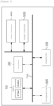
- FIG. 3 is a block diagram of a battery charging control apparatus according to embodiments of the present invention.
- the battery charging control 1000 may include a memory 100, a processor 200, a transceiver 300, an input interface 400, an output interface 500, and a storage device 600.
- respective components 100, 200, 300, 400, 500, 600 included in the battery charging control apparatus 1000 may be connected by a bus 700 to communicate with each other.
- the memory 100 and the storage device 600 among the components 100, 200, 300, 400, 500, 600 may include at least one of a volatile storage medium and a non-volatile storage medium.
- the memory 100 and the storage device 600 may include at least one of read only memory (ROM) and random access memory (RAM).
- the memory 100 may include at least one instruction executed by the processor 200.
- the at least one instruction may include an instruction to monitor state of charge (SOC) of the battery to be charged; an instruction to charge the battery according to a predefined charging current value based on the state of charge (SOC) of the battery; an instruction to determine the charging current value based on a voltage value of the battery regardless of the state of charge in the instance that the voltage value of the battery reaches a preset threshold value during the charge process of the battery; and an instruction to charge the battery according to the determined charging current value.
- SOC state of charge
- SOC state of charge
- the instruction to charge the battery according to a predefined charging current value may include an instruction to check a N-th section to which the SOC of the battery belongs and an instruction to charge the battery with a charging current value stored corresponding to the N-th section.
- the charging current value corresponding to the N-th section may be defined as a value smaller than a charging current value corresponding to the (N-1)-th section.
- the instruction to determine the charging current value may include an instruction to monitor whether the voltage value of the battery reaches a voltage threshold value stored corresponding to the N-th section.
- the instruction to determine the charging current value may include an instruction to determine the charging current value stored corresponding to the (N+1)-th section as the charging current value for charging the battery in the instance that the voltage value of the battery reaches the voltage threshold value corresponding to the N-th section.
- the voltage threshold value corresponding to the N-th section may be defined as a value greater than the voltage threshold value corresponding to the (N-1)-th section.
- the at least one instruction may further include an instruction to control to terminate the charge process of the battery when the battery voltage value reaches the voltage threshold value of the last section.
- the processor 200 may mean a central processing unit (CPU), a graphics processing unit (GPU), or a dedicated processor on which methods according to embodiments of the present invention are performed.
- CPU central processing unit
- GPU graphics processing unit
- dedicated processor on which methods according to embodiments of the present invention are performed.
- the processor 200 may execute at least one program command stored in the memory 100 as described above.
- a battery charging system including a battery charging control apparatus according to embodiments of the present invention has been described above.
- a battery charging control method performed by processor operations of the battery charging control apparatus according to embodiments of the present invention will be described in more detail.
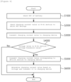
- FIG. 4 is a flowchart illustrating a battery charging control method performed by a processor in a battery charging control apparatus according to embodiments of the present invention.
- the battery charging control apparatus 5000 may check the state of charge information of the battery 1000 according to operations of the processor 200 (S1000).
- the battery charging control apparatus 5000 may monitor the state information of the battery 1000 in real time, obtain and confirm the state of charge information.
- the battery charging control apparatus 5000 may receive state information of the battery 1000 in real time from a separate monitoring device (not shown). Accordingly, the battery charging control apparatus 5000 may check the state of charge information of the battery 1000 among the state information received from the monitoring device.
- the battery charging control apparatus 5000 may check the section to which the state of charge information belongs and check the charging current value corresponding to the section (S2000).
- the battery charging control apparatus 5000 may transmit the confirmed charging current value to the charging device 3000 (S3000). Accordingly, the charging device 3000 may charge the battery 1000 by applying a charging current of a magnitude corresponding to the charging current value to the battery 1000.
- the battery charging control apparatus 5000 may check voltage values obtained through real-time monitoring of the battery 1000 while charging the battery 1000 according to the charging current value.
- the battery charging control apparatus 5000 may adjust the charging current value. For example, the battery charging control apparatus 5000 may retransmit the charging current value corresponding to the N+1 section of the state of charge information to the charging device 3000 (S5000). Accordingly, the magnitude of the charging current of the charging device 3000 may be changed from the charging current value corresponding to the N-th section to the charging current value corresponding to the (N+1)-th section.
- the magnitude of the charging current value may decrease as the state of charge (SOC) increases as described above. Accordingly, when the voltage value of the battery 1000 reaches the voltage threshold value corresponding to the N-th section, which is a state of charge information section in which a corresponding charging current value is set, the battery charging control apparatus 5000 may adjust the magnitude of the charging current for the charging device downward.
- SOC state of charge
- the battery charging control apparatus 5000 may use the charging current value and voltage threshold value information which are preset for each section based on the state of charge information of the battery when determining the charging current value.
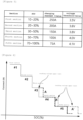
- the information may be provided in a form of a table type charge map, as shown in FIG. 5 below.
- FIG. 5 is a table summarizing state information of a battery in a battery charging control method performed by a battery charging control apparatus of according to embodiments of the present invention
- FIG. 6 is a graph for explaining a battery charging control method based on the table of FIG. 5 according to embodiments of the present invention.
- the value of the charging current may be provided as 200A and the corresponding voltage threshold value may be set to 3.6V.
- the charging current value may be provided as 150A and the corresponding voltage threshold value may be set to 3.8V.
- the value of the charging current may be provided as 100A and the corresponding voltage threshold value may be set to 4.0V.
- the value of the charging current may be provided as 75A and the corresponding voltage threshold value may be set to 4.1V.
- the magnitude of the charging current for charging the battery 1000 may be controlled for each section according to the state of charge information and the voltage threshold value.
- the charging current value may be reduced as the section number becomes higher in order to prevent lithium plating that may occur on the negative electrode surface of the battery when rapidly charging the battery, as described above.
- the voltage threshold value may increase as the section number becomes higher to prevent battery degradation.
- the battery charging control apparatus 5000 may set the charging current value to prevent lithium precipitation in a specific section (N-th section) based on real-time state of charge information of the battery and monitor the real-time voltage measurement value of the battery, and, when the predefined voltage threshold value in the corresponding section (N-th section) is reached, the battery charging control apparatus may adjust the previously set charging current value downward to the charging current value belonging to the next section (N+1 section) so as to prevent battery deterioration.
- the battery charging control apparatus 5000 may determine the charging current value based on the voltage state of the battery without considering changes in the state of charge information of the battery 1000, as in step S6000 of FIG. 4 , and may transmit the determined charging current value to the charging device 3000.
- the battery charging control apparatus may determine 250A belonging to the first section as the charging current value and transmit the charging current value to the charging device 3000. Accordingly, the battery 1000 may be charged with the charging current of 250A.
- the battery charging control apparatus may monitor status information of the battery 1000 being charged with the charging current of 250A.
- the battery charging control apparatus 5000 may transmit a signal for changing the charging current value to the charging device 3000 so that the battery 1000 is charged with 200A, which is the charging current value corresponding to the second section. Accordingly, the battery 1000 may be charged with a charging current of 200A.
- the battery charging control apparatus may monitor status information of the battery 1000 being charged with the charging current of 200A.
- the battery charging control apparatus 5000 may transmit a signal for changing the charging current value to the charging device 3000 so that the battery 1000 is charged with 150A, which is the charging current value corresponding to the third section. Accordingly, the battery 1000 may be charged with a charging current of 150A.
- the battery charging control apparatus may monitor status information of the battery 1000 being charged with the charging current of 150A.
- the battery charging control apparatus 5000 may transmit a signal for changing the charging current value to the charging device 3000 so that the battery 1000 is charged with 100A, which is the charging current value corresponding to the fourth section. Accordingly, the battery 1000 may be charged with a charging current of 100A.
- the battery charging control apparatus may monitor status information of the battery 1000 being charged with the charging current of 100A.
- the battery charging control apparatus 5000 may maintain the charging current value of 100A which belongs to the fourth section and charge the battery 1000 without any charging current change, despite that the state of charge (SOC) corresponds to the fifth section.
- the battery charging control apparatus may monitor status information of the battery 1000 being charged with the charging current of 100A and then, when the voltage value of the battery 1000 reaches 4.0V which belongs to the fifth section (P6), the battery charging control apparatus 5000 may transmit a signal for changing the charging current value to the charging device 3000 regardless of the state of charge information, so that the battery 1000 is charged with 75A, which is the charging current value corresponding to the fifth section. Accordingly, the battery 1000 may be charged with a charging current of 75A.
- the battery charging control apparatus may monitor status information of the battery 1000 being charged with the charging current of 75A, and when the voltage value of the battery 1000 reaches 4.1V, which is the voltage threshold value of the fifth section (the last section) (P7), the battery charging control apparatus 5000 may transmit a charging termination signal to the charging device 3000. Accordingly, charging of the battery 1000 may be terminated.
- the battery charging control apparatus 5000 may determine the charging current value step by step by using the state of charge information of the battery 1000.
- the battery charging control apparatus 5000 may change the charging current value based on the voltage value of the battery 1000.
- the battery charge control apparatus may determine the charging current value step by step based on the voltage value of the battery 1000, without considering the state of charge information of the battery 1000 as in the cases of P5 and P6 in the subsequent sections, whereas, when the voltage value of the battery 1000 reaches the threshold value of the final section, as in the case of P7, the battery charge control apparatus may transmit a charging termination signal.
- FIG. 7 is a graph for explaining a battery charging control method according to a comparative example of the present invention.
- a battery charging control apparatus 5000 controls the charging current of the charging device 3000 by temporarily adjusting the charging current value downward only in a corresponding section (N-th section) to prevent battery deterioration, and thus, the amount of charging current equivalent to area A cannot be applied, thereby increasing charging time and lowering charging efficiency.
- the battery charging control apparatus 5000 may determine a charging current value for each section based on a voltage value of the battery 1000 after downward adjustment of the charging current, thereby maintaining the charging current value without any reduction until the voltage threshold value predefined for each section is reached. Accordingly, the battery charging control apparatus 5000 according to embodiments of the present invention may compensate for the charge loss equivalent to the area A in the N-th section caused by downward adjustment of the charging current value, in the next SOC sections after the N-th section, such as A', and thus, lithium precipitation and battery deterioration due to rapid charging can be prevented as well as charging time can be shortened.
- a battery charging control apparatus and method may charge the battery with a predefined charging current magnitude belonging to a corresponding section based on the state of charge (SOC) of the battery to be charged, charge the battery by adjusting the charging current downwards to magnitude of the charging current of the next section when the battery voltage exceeds a predefined threshold value during charging, determine the magnitude of the charging current for each section based on real-time voltage information, not the state of charge (SOC) information of the battery, and charge the battery with the determined charging current until the battery is fully charged, and thus, lithium precipitation and battery deterioration due to quick charging can be prevented and charging time can be shortened.
- SOC state of charge
- the operations of the method according to the embodiments and experimental examples of the present invention may be implemented as a computer-readable program or code on a computer-readable recording medium.
- the computer-readable recording medium includes all types of recording devices in which data readable by a computer system is stored.
- the computer-readable recording medium may be distributed in a network-connected computer system to store and execute computer-readable programs or codes in a distributed manner.
- the computer-readable recording medium may include hardware devices specially configured to store and execute program instructions, such as ROM, RAM, flash memory, etc.
- the program instructions may include not only machine language code created by a compiler, but also high-level language code that can be executed by a computer using an interpreter.
- a block or apparatus corresponds to a method step or feature of a method step.
- aspects described in the context of a method may also represent a feature of a corresponding block or item or a corresponding apparatus.
- Some or all of the method steps may be performed by (or using) a hardware device, such as, for example, a microprocessor, a programmable computer, or an electronic circuit. In some embodiments, one or more of the most important method steps may be performed by such an apparatus.
Landscapes
- Engineering & Computer Science (AREA)
- Power Engineering (AREA)
- Manufacturing & Machinery (AREA)
- Chemical & Material Sciences (AREA)
- Chemical Kinetics & Catalysis (AREA)
- Electrochemistry (AREA)
- General Chemical & Material Sciences (AREA)
- Physics & Mathematics (AREA)
- General Physics & Mathematics (AREA)
- Charge And Discharge Circuits For Batteries Or The Like (AREA)
- Secondary Cells (AREA)
Applications Claiming Priority (2)
| Application Number | Priority Date | Filing Date | Title |
|---|---|---|---|
| KR1020220152598A KR20240070995A (ko) | 2022-11-15 | 2022-11-15 | 배터리 충전 제어 장치 및 방법, 그리고 이를 포함하는 배터리 시스템 |
| PCT/KR2023/009736 WO2024106668A1 (ko) | 2022-11-15 | 2023-07-10 | 배터리 충전 제어 장치 및 방법, 그리고 이를 포함하는 배터리 시스템 |
Publications (2)
| Publication Number | Publication Date |
|---|---|
| EP4518089A1 true EP4518089A1 (de) | 2025-03-05 |
| EP4518089A4 EP4518089A4 (de) | 2025-10-01 |
Family
ID=91085028
Family Applications (1)
| Application Number | Title | Priority Date | Filing Date |
|---|---|---|---|
| EP23891742.1A Pending EP4518089A4 (de) | 2022-11-15 | 2023-07-10 | Batterieladesteuerungsvorrichtung und -verfahren sowie batteriesystem damit |
Country Status (5)
| Country | Link |
|---|---|
| EP (1) | EP4518089A4 (de) |
| JP (1) | JP2025515699A (de) |
| KR (1) | KR20240070995A (de) |
| CN (1) | CN119256465A (de) |
| WO (1) | WO2024106668A1 (de) |
Families Citing this family (2)
| Publication number | Priority date | Publication date | Assignee | Title |
|---|---|---|---|---|
| KR20260013590A (ko) * | 2024-07-22 | 2026-01-29 | 주식회사 엘지에너지솔루션 | 배터리 충전 제어 장치 및 방법, 그리고 이를 포함하는 배터리 시스템 |
| KR20260046639A (ko) * | 2024-09-30 | 2026-04-07 | 주식회사 엘지에너지솔루션 | 배터리 충전 제어 장치 및 방법, 그리고 이를 포함하는 배터리 시스템 |
Family Cites Families (10)
| Publication number | Priority date | Publication date | Assignee | Title |
|---|---|---|---|---|
| KR101288122B1 (ko) * | 2011-01-03 | 2013-07-18 | 삼성에스디아이 주식회사 | 배터리 충전방법, 및 이를 적용한 배터리 팩 |
| KR101303164B1 (ko) * | 2012-01-04 | 2013-09-09 | 엘지전자 주식회사 | 배터리충전장치, 이를 포함하는 에너지저장시스템, 및 배터리충전방법 |
| JP6236920B2 (ja) * | 2013-06-27 | 2017-11-29 | 株式会社豊田自動織機 | 充電電流の多段階制御方法および多段階制御装置 |
| KR101546940B1 (ko) | 2014-01-14 | 2015-08-25 | 주식회사 알파트로닉스 | 배터리 급속 충전 장치 및 방법 |
| JP6145712B2 (ja) * | 2014-03-24 | 2017-06-14 | パナソニックIpマネジメント株式会社 | 二次電池の充電システム及び方法並びに電池パック |
| US10291047B2 (en) * | 2014-06-26 | 2019-05-14 | Intel Corporation | Adaptive step and charge current battery charging |
| US11056900B2 (en) * | 2018-01-31 | 2021-07-06 | Ningde Amperex Technology Limited | Charging method, charging device, and computer-readable medium for charging a battery |
| JP2020036393A (ja) * | 2018-08-27 | 2020-03-05 | ヤマハ発動機株式会社 | 充電所要時間推定方法、充電所要時間推定装置および電動車両 |
| KR102772378B1 (ko) * | 2020-08-13 | 2025-02-21 | 주식회사 엘지에너지솔루션 | 배터리 관리 시스템, 배터리 관리 방법, 배터리 팩 및 전기 차량 |
| KR20220152598A (ko) | 2021-05-10 | 2022-11-17 | 주식회사 바른생각 | 통합 학원 운영 서버 및 그 동작 방법 |
-
2022
- 2022-11-15 KR KR1020220152598A patent/KR20240070995A/ko active Pending
-
2023
- 2023-07-10 JP JP2024566005A patent/JP2025515699A/ja active Pending
- 2023-07-10 WO PCT/KR2023/009736 patent/WO2024106668A1/ko not_active Ceased
- 2023-07-10 EP EP23891742.1A patent/EP4518089A4/de active Pending
- 2023-07-10 CN CN202380040718.0A patent/CN119256465A/zh active Pending
Also Published As
| Publication number | Publication date |
|---|---|
| WO2024106668A1 (ko) | 2024-05-23 |
| KR20240070995A (ko) | 2024-05-22 |
| CN119256465A (zh) | 2025-01-03 |
| JP2025515699A (ja) | 2025-05-20 |
| EP4518089A4 (de) | 2025-10-01 |
Similar Documents
| Publication | Publication Date | Title |
|---|---|---|
| KR102493232B1 (ko) | 배터리 관리 장치 | |
| EP2192649B1 (de) | Energiespeichersystem | |
| US10263434B2 (en) | Charge and discharge device, charge and discharge control method, and program | |
| EP4518089A1 (de) | Batterieladesteuerungsvorrichtung und -verfahren sowie batteriesystem damit | |
| US12449485B2 (en) | Battery management apparatus and method | |
| EP2549579A1 (de) | Batteriesystem | |
| US20260110739A1 (en) | Battery State Management Apparatus and Operating Method Thereof | |
| EP3839532A1 (de) | Vorrichtung und verfahren zur bestimmung des ladezustandes | |
| EP4239348B1 (de) | Vorrichtung und verfahren zur schätzung der kapazität einer batteriezelle | |
| EP4404417A1 (de) | Batteriesteuerungssystem und verfahren zur verwaltung des batteriezustands | |
| US20240243595A1 (en) | Battery Management Apparatus and Operating Method Thereof | |
| EP4207548B1 (de) | Batterieverwaltungsvorrichtung und betriebsverfahren dafür | |
| CN112117505A (zh) | 一种化成分容控制方法及化成分容控制系统 | |
| EP4406770B1 (de) | Batterieschutzvorrichtung und -verfahren | |
| KR20260017032A (ko) | 배터리 충전 제어 장치 및 방법, 그리고 이를 포함하는 배터리 시스템 | |
| EP4462633A1 (de) | Batteriesystem zum sequenziellen laden von batterien und steuerungsverfahren dafür | |
| KR20260013590A (ko) | 배터리 충전 제어 장치 및 방법, 그리고 이를 포함하는 배터리 시스템 | |
| KR20260013591A (ko) | 배터리 충전 제어 장치 및 방법, 그리고 이를 포함하는 배터리 시스템 | |
| CN116148676B (zh) | 自放电异常电芯的判断方法、判断装置及电子设备 | |
| JP6342306B2 (ja) | 車両用電池制御装置及び車両用電池制御方法 | |
| CN112684353B (zh) | 电池模块的电流传输状态的控制及电池容量的校准方法 | |
| EP4447258A1 (de) | Vorrichtung und verfahren zur steuerung des ladens eines batteriepacks | |
| EP4307516A1 (de) | Batterieverwaltungsvorrichtung und -verfahren | |
| KR20260046639A (ko) | 배터리 충전 제어 장치 및 방법, 그리고 이를 포함하는 배터리 시스템 | |
| KR20250094035A (ko) | 배터리 관리 장치 및 방법, 그리고 이를 포함하는 시스템 |
Legal Events
| Date | Code | Title | Description |
|---|---|---|---|
| STAA | Information on the status of an ep patent application or granted ep patent |
Free format text: STATUS: THE INTERNATIONAL PUBLICATION HAS BEEN MADE |
|
| PUAI | Public reference made under article 153(3) epc to a published international application that has entered the european phase |
Free format text: ORIGINAL CODE: 0009012 |
|
| STAA | Information on the status of an ep patent application or granted ep patent |
Free format text: STATUS: REQUEST FOR EXAMINATION WAS MADE |
|
| 17P | Request for examination filed |
Effective date: 20241129 |
|
| AK | Designated contracting states |
Kind code of ref document: A1 Designated state(s): AL AT BE BG CH CY CZ DE DK EE ES FI FR GB GR HR HU IE IS IT LI LT LU LV MC ME MK MT NL NO PL PT RO RS SE SI SK SM TR |
|
| A4 | Supplementary search report drawn up and despatched |
Effective date: 20250901 |
|
| RIC1 | Information provided on ipc code assigned before grant |
Ipc: H02J 7/00 20060101AFI20250826BHEP Ipc: G01R 19/165 20060101ALI20250826BHEP Ipc: H01M 10/44 20060101ALI20250826BHEP |
|
| DAV | Request for validation of the european patent (deleted) | ||
| DAX | Request for extension of the european patent (deleted) |