EP4518123A1 - Filter für elektromagnetische kompatibilität, elektrischer gleichspannungswandler mit einem solchen filter, mobilitätsmaschine mit einem solchen wandler oder einem solchen filter und verfahren zur herstellung eines solchen filters - Google Patents
Filter für elektromagnetische kompatibilität, elektrischer gleichspannungswandler mit einem solchen filter, mobilitätsmaschine mit einem solchen wandler oder einem solchen filter und verfahren zur herstellung eines solchen filters Download PDFInfo
- Publication number
- EP4518123A1 EP4518123A1 EP24198308.9A EP24198308A EP4518123A1 EP 4518123 A1 EP4518123 A1 EP 4518123A1 EP 24198308 A EP24198308 A EP 24198308A EP 4518123 A1 EP4518123 A1 EP 4518123A1
- Authority
- EP
- European Patent Office
- Prior art keywords
- capacitor
- conductor
- pin
- clamp
- axis
- Prior art date
- Legal status (The legal status is an assumption and is not a legal conclusion. Google has not performed a legal analysis and makes no representation as to the accuracy of the status listed.)
- Pending
Links
Images




Classifications
-
- H—ELECTRICITY
- H01—ELECTRIC ELEMENTS
- H01F—MAGNETS; INDUCTANCES; TRANSFORMERS; SELECTION OF MATERIALS FOR THEIR MAGNETIC PROPERTIES
- H01F17/00—Fixed inductances of the signal type
- H01F17/04—Fixed inductances of the signal type with magnetic core
- H01F17/06—Fixed inductances of the signal type with magnetic core with core substantially closed in itself, e.g. toroid
-
- H—ELECTRICITY
- H03—ELECTRONIC CIRCUITRY
- H03H—IMPEDANCE NETWORKS, e.g. RESONANT CIRCUITS; RESONATORS
- H03H1/00—Constructional details of impedance networks whose electrical mode of operation is not specified or applicable to more than one type of network
-
- H—ELECTRICITY
- H02—GENERATION; CONVERSION OR DISTRIBUTION OF ELECTRIC POWER
- H02M—APPARATUS FOR CONVERSION BETWEEN AC AND AC, BETWEEN AC AND DC, OR BETWEEN DC AND DC, AND FOR USE WITH MAINS OR SIMILAR POWER SUPPLY SYSTEMS; CONVERSION OF DC OR AC INPUT POWER INTO SURGE OUTPUT POWER; CONTROL OR REGULATION THEREOF
- H02M1/00—Details of apparatus for conversion
-
- H—ELECTRICITY
- H02—GENERATION; CONVERSION OR DISTRIBUTION OF ELECTRIC POWER
- H02M—APPARATUS FOR CONVERSION BETWEEN AC AND AC, BETWEEN AC AND DC, OR BETWEEN DC AND DC, AND FOR USE WITH MAINS OR SIMILAR POWER SUPPLY SYSTEMS; CONVERSION OF DC OR AC INPUT POWER INTO SURGE OUTPUT POWER; CONTROL OR REGULATION THEREOF
- H02M1/00—Details of apparatus for conversion
- H02M1/44—Circuits or arrangements for compensating for electromagnetic interference in converters or inverters
-
- H—ELECTRICITY
- H02—GENERATION; CONVERSION OR DISTRIBUTION OF ELECTRIC POWER
- H02M—APPARATUS FOR CONVERSION BETWEEN AC AND AC, BETWEEN AC AND DC, OR BETWEEN DC AND DC, AND FOR USE WITH MAINS OR SIMILAR POWER SUPPLY SYSTEMS; CONVERSION OF DC OR AC INPUT POWER INTO SURGE OUTPUT POWER; CONTROL OR REGULATION THEREOF
- H02M3/00—Conversion of DC power input into DC power output
- H02M3/003—Constructional details, e.g. physical layout, assembly, wiring or busbar connections
-
- H—ELECTRICITY
- H03—ELECTRONIC CIRCUITRY
- H03H—IMPEDANCE NETWORKS, e.g. RESONANT CIRCUITS; RESONATORS
- H03H1/00—Constructional details of impedance networks whose electrical mode of operation is not specified or applicable to more than one type of network
- H03H1/0007—Constructional details of impedance networks whose electrical mode of operation is not specified or applicable to more than one type of network of radio frequency interference filters
-
- H—ELECTRICITY
- H01—ELECTRIC ELEMENTS
- H01F—MAGNETS; INDUCTANCES; TRANSFORMERS; SELECTION OF MATERIALS FOR THEIR MAGNETIC PROPERTIES
- H01F17/00—Fixed inductances of the signal type
- H01F17/04—Fixed inductances of the signal type with magnetic core
- H01F17/06—Fixed inductances of the signal type with magnetic core with core substantially closed in itself, e.g. toroid
- H01F2017/065—Core mounted around conductor to absorb noise, e.g. EMI filter
-
- H—ELECTRICITY
- H03—ELECTRONIC CIRCUITRY
- H03H—IMPEDANCE NETWORKS, e.g. RESONANT CIRCUITS; RESONATORS
- H03H1/00—Constructional details of impedance networks whose electrical mode of operation is not specified or applicable to more than one type of network
- H03H2001/0021—Constructional details
Definitions
- the present invention relates to an electromagnetic compatibility filter, a DC-DC electrical converter comprising such a filter, a mobility device comprising such a converter or such a filter and a method of manufacturing such a filter.
- a mobility device is, for example, a motorized land vehicle, a train, an aircraft or a drone.
- a motorized land vehicle is, for example, a motor vehicle, a motorcycle, a motorized bicycle or a motorized wheelchair.
- the clamp of the first conductor is closed on its associated pin by a tool, in particular a fixing clamp having two elements designed to be placed respectively on each side of this clamp.
- the clamp may be a clamping clamp, in which case the elements are designed to approach each other to mechanically push respectively the two branches of the clamp so that they clamp the associated pin.
- the clamp may alternatively or in addition be a welding clamp, in which case the elements form electrodes to pass a current through the clamp to be closed and the associated pin to weld them to each other.
- the elongated body of the third conductor must pass away from the clamp, which increases the overall size of the filter.
- the elongated body can start at an angle at the level of the first and second clamps, and therefore move away from the clamp of the third conductor to pass at a sufficient distance from the latter, while keeping the second capacitance close to the third capacitance.
- the invention may further comprise one or more of the following optional features, in any technically possible combination.
- the first clamp of the third conductor is higher than the second clamp of the third conductor.
- the capacitors have respective housings of generally parallelepiped shape with upper faces perpendicular to the vertical axis, the upper face of the first capacitor extending higher than the upper face of the second capacitor and the upper face of the third capacitor extending below the upper face of the second capacitor.
- the first capacitor has another pin parallel to the first pin
- the second capacitor has another pin parallel to the first pin, a first plane defined by the two pins of the first capacitor and a second plane defined by the two pins of the second capacitor being substantially parallel, the first plane extending above the second plane.
- the elongate body has a straight end portion from which the clamps of the third conductor project substantially perpendicularly, this straight end portion deviating horizontally from the clamp of the first conductor by following this straight end portion from the clamps of the third conductor.
- the use of the elements involves bringing the elements closer to each other.
- use of the elements includes using the elements as electrodes to pass a current through the clamp and associated pin to weld them together.
- a mobility device comprising an electromagnetic compatibility filter according to the invention or a DC-DC electrical converter according to the invention.
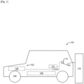
- the mobility device 100 comprises a propulsion system 102, for example drive wheels 104 and an electric motor 106 configured to drive the drive wheels 104.
- the mobility device 100 further comprises a battery 108 configured to electrically power the electric motor 106.
- the mobility device 100 To recharge the battery 108 at a charging station 110 connected to an electrical distribution network (not shown), the mobility device 100 further comprises an electrical outlet 112 designed to be connected to the charging station 110, as well as a DC-DC electrical converter 114 connected between the electrical outlet 112 and the battery 108, in order to convert an input voltage VIN received from the charging station 110 through the electrical outlet 112 into an output voltage VOUT supplied to the battery 108.
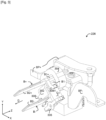
- the arrangement of the various elements of the converter 114 will refer to an arbitrary reference frame comprising a left-right X axis, a bottom-top Y axis and a front-rear Z axis.
- the converter 114 first comprises a housing 202 comprising side walls 204 and a bottom 206 together defining an interior space 208 of the housing 202 and an exterior space 210 to the housing 202.
- the side walls 204 may further define, opposite the bottom 206, an upper opening 212.
- the housing 202 may further comprise a cover 214 designed to close the upper opening 212.
- the converter 114 further comprises an electrical conversion circuit 218 extending in the interior space 208 of the housing 202.
- the electrical conversion circuit 218 is designed to convert the input voltage VIN into the output voltage VOUT.
- the converter 114 may be a parallel chopper (“boost converter” or “step-up converter” in English), in which case the conversion circuit 218 comprises for example a positive branch 220 and a negative branch 222, having an input side and an output side.
- the conversion circuit 218 comprises an inductance L on the positive branch, as well as a switch Q1 and a capacitor C, in parallel with each other between the positive branch 220 and the negative branch 222, on the output side with respect to the inductance L, and another switch Q2 on the positive branch, between the switch Q1 and the capacitor C, for example a diode passing towards the capacitor C (its cathode on the side of the capacitor C).
- the converter 114 then further comprises a control circuit 220 designed to control the switch Q to carry out the conversion.
- the converter 114 further comprises an input connector 224 accessible from the external space 210 in order to be connected to the external socket 112 by an electrical connection (not shown) having, at one of its ends, a connector complementary to the input connector 224.
- the input connector 224 thus comprises two input pins B'+, B'-: the first pin B'+ is said to be positive to receive the positive potential of the input voltage VIN and the second pin B'- is said to be negative to receive the negative potential of the input voltage VIN.
- the converter 114 further comprises an output connector 226 accessible from the external space 210 in order to be connected to the battery 108 by an electrical connection (not shown) having, at one of its ends, a connector complementary to the output connector 226.
- the output connector 226 thus comprises two output pins B+, B-: the first pin B+ is said to be positive to provide the positive potential of the output voltage VOUT and the second pin B- is said to be negative to provide the negative potential of the output voltage VOUT.
- the converter 114 has a second main bus bar, called negative, BP- connecting the negative input pin B'- and the negative output pin B- to each other, as well as to the negative line 222 of the conversion circuit 218.
- the converter 114 further comprises a main positive input bus bar BP'+ connecting the positive input pin B'+ to the input side of the positive branch 220 of the conversion circuit 218, and a first main bus bar, called the positive output bus bar, BP+ connecting the positive output pin B+ to the output side of the positive branch 220 of the conversion circuit 218.
- the converter 114 may further comprise a switch 228 for selectively connecting and disconnecting the positive main bus bars BP+, BP'+. This makes it possible to short-circuit the conversion circuit 218 so that the output voltage VOUT is equal to the input voltage VIN. This function is useful for example when the charging station 110 provides an input voltage VIN which is already at the voltage necessary for recharging the battery 108.
- the output pins B+, B- comprise for example respectively two flat busbars, for example with a thickness of between 1 mm and 5 mm, for example 4 mm, each having a flat fixing portion B1+, B1- and a flat end portion B2+, B2-.
- the end portions B2+, B2- project for example towards the external space 210 along an axis D (in the forward direction in the illustrated example) and are designed to be connected to the complementary connector of the output connector 226 along this axis D.
- the end portions B2+, B2- could have a geometry other than flat, for example a geometry of a rod with a circular section projecting along the axis D.
- planar fixing portions B1+, B1- extend substantially parallel, for example to within 1°, one opposite the other, for example less than 10 mm from each other, for example 4 mm from each other.
- planar end portions B2+, B2- extend substantially parallel, for example to within 1°, one opposite the other, but at a greater distance than the planar fixing portions B1+, B1-, for example at least twice as great, for example between 20 mm and 30 mm from each other, for example 25.7 mm from each other.
- one of the output pins B+, B- e.g. the positive output pin B+, as in the illustrated example
- the other of the output pins B+, B- e.g. the negative connection pin B-, as in the illustrated example
- the output connector 226 further comprises a first electromagnetic compatibility filter.
- This first filter comprises, for example, first of all a magnetic core 304 surrounding the output pins B+, B-, and more precisely the fixing portions B1+, B1- due to their small spacing.
- the first filter further comprises, for example, two capacitors C+, C- connected between a bus bar 306 connected to an electrical ground (for example, the housing 202) and respectively the positive output pin B+ and the negative output pin B-.
- the positive output pin B+ comprises a tab 308+ extending from the flat bus bar to the capacitor C+.
- the negative output pin B- may comprise a tab 308- extending from the flat bus bar to the capacitor C-.
- the output connector 226 further comprises two auxiliary bus bars BA+, BA-.
- the first BA+ is said to be positive and is interposed between the positive pin B+ and the positive main bus bar BP+.
- the second BA- is said to be negative and is interposed between the negative pin B- and the negative bus bar BP-.
- each auxiliary bus bar BA+, BA- comprises a first flat portion BA1+, BA1- fixed on the positive pin B+, respectively negative B-, and more precisely on its fixing portion B1+, respectively B1-.
- the flat portions BA1+, BA1- of the auxiliary bus bars BA+, BA- are for example pressed against and fixed against faces of the fixing portions B1+, B1-.
- the fixing portions B1+, B1- have facing faces (facing each other) and external faces, on the other side of the facing faces.
- the flat portions BA1+, BA1- of the auxiliary bus bars BA+, BA- are for example pressed against and fixed against these external faces (as in the example illustrated).
- Each auxiliary bus bar BA+, BA- further comprises a second flat portion BA2+, BA2-.
- These second flat portions BA2+, BA2- are substantially parallel, for example to within 1°, to each other, for example coplanar.
- each portion BA2+, BA2- may extend in continuity with the first portion plane BA1+, BA1- (in which case the auxiliary busbars BA+, BA- are flat) or with a non-flat angle (as in the example illustrated).
- each auxiliary busbar BA+, BA- has for example a bend P+, P- between the portions BA1+, BA2+ and BA1-, BA2-, substantially parallel to the axis D, for example to within 1°.
- the converter 114 further comprises a second electromagnetic compatibility filter 600 for the output connector 226.
- This electromagnetic compatibility filter 600 firstly comprises a negative bus bar LD- connected to the negative main bus bar BP-.
- the negative bus bar LD- comprises for example a fixing terminal 602 fixed to the negative main bus bar BP-, for example by the same screw as the negative auxiliary bus bar BA-.
- the electromagnetic compatibility filter 600 further comprises a positive bus bar LD+ connected to the positive main output bus bar BP+.
- the bus bar LD+ comprises for example a fixing terminal 604 fixed to the positive main output bus bar BP+, for example by the same screw as the positive auxiliary bus bar BA+.
- the electromagnetic compatibility filter 600 further comprises a ground bus bar LD0 connected to the electrical ground, for example to the housing 202.
- the ground bus bar LD0 comprises a fixing terminal 606 fixed to the electrical ground.
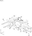
- the electromagnetic compatibility filter 600 further comprises a capacitor C1 connected between the negative bus bar LD- and the ground bus bar LD0, a capacitor C2 connected between the positive bus bar LD+ and the ground bus bar LD0, and a capacitor C3 connected between the positive bus bar LD+ and the negative bus bar LD-.
- All the capacitors C1, C2, C3 have, for example, respective housings of generally parallelepipedal shape with horizontal upper faces, parallel to each other, perpendicular to the Y axis.
- the capacitor C1 has two pins C1A, C1B projecting along axes D1A, D1B, parallel to the Z axis in the example illustrated.
- the negative bus bar LD- has a clamp P1A clamping the pin C1A
- the ground bus bar LD0 has a clamp P1B clamping the pin C1B.
- the clamp P1B projects, that is to say opens, along a so-called oblique axis and a direction A1 on this axis.
- the capacitor C2 has two pins C2A, C2B projecting along axes D2A, D2B.
- the positive bus bar LD+ has a clamp P2A enclosing the pin C2A
- the ground bus bar LD0 has a clamp P2B enclosing the pin C2B.
- the clamp P2B projects, i.e. opens, along the same axis, for example to within 1°, as the axis of the clamp P1B, and in a direction A2.
- the clamps P1B and P2B are positioned head to tail, i.e. the directions A1, A2 are opposite.
- the capacitor C3 has two pins C3A, C3B (each of which can be split as in the example illustrated) projecting in forward directions D3A, D3B.
- the positive bus bar LD+ has a clamp P3A enclosing the pin C3A.
- This clamp P3A projects, i.e. opens, in the vertical axis Y in the direction A3 upwards.
- the negative bus bar LD- also has a clamp P3B which projects, i.e. opens, in the vertical axis Y in the direction A3 upwards and enclosing the pin C3B.
- the ground conductor LD0 has an elongated body 702 extending from the clamps P1B, P2B downward, at least to the level of the pin C3A.
- the terminal 606 of the ground conductor LD0 is located lower than this pin C3A, so that the elongated body 702 passes on the side of the pin C3A and between the pins C3A and C3B.
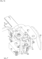
- each clamp P1A, P1B, P2A, P2B, P3A, P3B is closed on its associated pin C1A, C1B, C2A, C2B, C3A, C3B by a tool, in particular a fixing clamp having two elements 802, 804 designed to be placed respectively on each side of the clamp P1A, P1B, P2A, P2B, P3A, P3B.
- the fixing clamp may be a clamping clamp, in which case the elements are designed to approach each other to mechanically push respectively the two branches of the clamp P1A, P1B, P2A, P2B, P3A, P3B so that they clamp the associated pin C1A, C1B, C2A, C2B, C3A, C3B.
- the fixing clamp may also be an electric welding clamp, in which case the elements 802, 804 additionally or alternatively form electrodes for passing a current through the clamp P1A, P1B, P2A, P2B, P3A, P3B and the associated pin C1A, C1B, C2A, C2B, C3A, C3B to weld them together.
- the elongated body of the ground bus bar LD0 must pass at a distance from the clamp P3A.
- the capacitors C1 and C2, which extend above the capacitor C3, be as close as possible to the latter.
- the capacitor C1 is placed so that its pin C1B is located higher than the pin C2B of the second capacitor C2.
- the opposite directions A1, A2 and the direction A3 make an angle between them of less than 80°, preferably less than 70°, for example 65°, which allows the elongated body 702 to have a straight end portion 801, from which the clamps P1B, P2B project substantially perpendicularly, for example to within 1°, which is vertically at an angle to move away from the clamp P3A.
- the capacitor C1 is placed so that its upper face extends higher than the upper face of the capacitor C2, i.e. at a higher height.
- the height of the upper face of the capacitor C1 is at least 5 mm, preferably at least 10 mm, higher than the height of the upper face of the capacitor C2.
- each capacitor C1, C2 define a straight line D1, D2.
- These two straight lines D1, D2 are substantially parallel, for example to within 1°, with the line D1 above the line D2, for example at least 5 mm above, for example between 5 mm and 10 mm above.
- the elongated body 702 would extend too close to the clamp P1B and/or the clamp P3A to allow the passage of the elements 802, 804 of the tool (see the area surrounded by dotted lines).
- the input connector 224 has elements similar to those of the output connector 226, for which the references of the preceding figures are repeated, with "'" to distinguish them.
- the input pins B'+, B'- are identical to the output pins B+, B', in particular of the same shape.
- the input pins B'+, B'- extend horizontally, that is to say perpendicular to the direction of fixing (for example screwing). Thus, there is no angle to compensate, so that the auxiliary bus bars BA'+, BA'- are flat.
- an electromagnetic compatibility filter 600' is also provided behind the input connector 224 and has elements similar to those of the electromagnetic compatibility filter 600, for which the references of the preceding figures are repeated, with " ' " to distinguish them.
- the capacitors C1', C2' are offset vertically in order to facilitate the passage of the bus bar LD0' at a distance from the clamp
- the output connector 226 is obtained by an identical process.
- the negative pin B'- and, for example, the bus bar 306' are obtained. Both are for example obtained overmolded by an overmolding 502', leaving the portions B1'-, B2'- of the negative pin B'- visible.
- the overmolding 502' further has a through opening 504' in a part of the overmolding 502' overmolding the portion B1'- of the negative pin B'-. In other exemplary embodiments, the overmolding 502' could be devoid of a through opening 504'.
- the magnetic torus 304' is obtained.
- the negative pin B'- is inserted, by its fixing portion B1'-, into the magnetic core 304', for example until the core 304' extends around the overmolding 502', for example around the part of the overmolding 302' having the through opening 504'.
- step E4 the negative auxiliary bus bar BA'- is obtained.
- the portion BA1'- of the negative auxiliary bus bar BA'- is pressed and fixed against the fixing portion B1'- of the negative pin B'-.
- the fixing is for example carried out by welding, for example by electric brazing and/or by depositing a silver link between the two portions BA1'-, B1'- to be fixed.
- the positive pin B'+ is inserted, by its fixing portion B1'+, into the torus 304', by offsetting, for example upwards as in the illustrated example, its fixing portion B1'+ from the fixing portion B1'- of the negative pin B'-.
- the positive pin B'+ is inserted into the through opening 504' of the overmolding 502', such that the torus 304' surrounds the fixing portion B1'+ of the positive pin B'+.
- step E8 we obtain the positive auxiliary bus bar BA'+.
- the portion BA1'+ of the positive auxiliary bus bar BA'+ is pressed and fixed against the fixing portion B1'+ of the positive pin B'+.
- This fixing is facilitated by the offset between the fixing portions B1'+, B1'- of the pins B'-, B'+, which allows access from both sides.
- the fixing is for example carried out by welding.
- the positive pin B'+ is slid downwards into the torus 304' to place the fixing portions B1'+, B1'- opposite each other.
- the positive pin B'+ is slid downwards into the through opening 504' of the overmolding 502'.
- this connector is assembled to the two main positive BP+ and negative BP- bus bars of the DC-DC voltage converter 114 according to an assembly method comprising a step F1 of obtaining a connector 226 according to the method of manufacturing a connector previously described, and a step of plating and fixing the flat portion BP2+ of the positive main bus bar BP+ and the flat portion BP2- of the negative main bus bar BP- against respectively the second flat portions BA2+, BA2- of the auxiliary bus bars BA+, BA-.
- this step of plating and fixing the flat portion BP2+ of the positive main bus bar BP+ and the flat portion BP2- of the negative main bus bar BP- against respectively the second portions BA2+, BA2- of the auxiliary bus bars BA+, BA- comprises a step of fixing by screwing the second portions BA2+, BA2- of the auxiliary bus bars BA+, BA- to the flat portions BP2+, BP2- of the main bus bars BP+, BP- in a screwing direction substantially perpendicular to the second portions BA2+, BA2- of the auxiliary bus bars BA+, BA-.
Landscapes
- Engineering & Computer Science (AREA)
- Power Engineering (AREA)
- Physics & Mathematics (AREA)
- Electromagnetism (AREA)
- Microelectronics & Electronic Packaging (AREA)
- Filters And Equalizers (AREA)
- Electric Propulsion And Braking For Vehicles (AREA)
Applications Claiming Priority (1)
| Application Number | Priority Date | Filing Date | Title |
|---|---|---|---|
| FR2309273A FR3152660B1 (fr) | 2023-09-04 | 2023-09-04 | Filtre de compatibilité électromagnétique, convertisseur électrique continu-continu comportant un tel filtre, engin de mobilité comportant un tel convertisseur ou un tel filtre, et procédé de fabrication d’un tel filtre |
Publications (1)
| Publication Number | Publication Date |
|---|---|
| EP4518123A1 true EP4518123A1 (de) | 2025-03-05 |
Family
ID=89767416
Family Applications (1)
| Application Number | Title | Priority Date | Filing Date |
|---|---|---|---|
| EP24198308.9A Pending EP4518123A1 (de) | 2023-09-04 | 2024-09-03 | Filter für elektromagnetische kompatibilität, elektrischer gleichspannungswandler mit einem solchen filter, mobilitätsmaschine mit einem solchen wandler oder einem solchen filter und verfahren zur herstellung eines solchen filters |
Country Status (4)
| Country | Link |
|---|---|
| US (1) | US20250079978A1 (de) |
| EP (1) | EP4518123A1 (de) |
| CN (1) | CN119561513A (de) |
| FR (1) | FR3152660B1 (de) |
Citations (3)
| Publication number | Priority date | Publication date | Assignee | Title |
|---|---|---|---|---|
| US20130279114A1 (en) * | 2010-12-27 | 2013-10-24 | Hitachi Automotive Systems, Ltd. | Vehicular Power Conversion Apparatus |
| US9159506B2 (en) * | 2008-10-29 | 2015-10-13 | Hitachi Automotive Systems, Ltd. | Capacitor module and power conversion device |
| WO2019002710A1 (fr) * | 2017-06-28 | 2019-01-03 | Valeo Equipements Electriques Moteur | Convertisseur de tension, procédé de fabrication d'un tel convertisseur de tension et ensemble d'un module principal et d'un module bornier pour former un tel convertisseur de tension |
-
2023
- 2023-09-04 FR FR2309273A patent/FR3152660B1/fr active Active
-
2024
- 2024-09-02 CN CN202411219559.3A patent/CN119561513A/zh active Pending
- 2024-09-03 EP EP24198308.9A patent/EP4518123A1/de active Pending
- 2024-09-04 US US18/824,567 patent/US20250079978A1/en active Pending
Patent Citations (3)
| Publication number | Priority date | Publication date | Assignee | Title |
|---|---|---|---|---|
| US9159506B2 (en) * | 2008-10-29 | 2015-10-13 | Hitachi Automotive Systems, Ltd. | Capacitor module and power conversion device |
| US20130279114A1 (en) * | 2010-12-27 | 2013-10-24 | Hitachi Automotive Systems, Ltd. | Vehicular Power Conversion Apparatus |
| WO2019002710A1 (fr) * | 2017-06-28 | 2019-01-03 | Valeo Equipements Electriques Moteur | Convertisseur de tension, procédé de fabrication d'un tel convertisseur de tension et ensemble d'un module principal et d'un module bornier pour former un tel convertisseur de tension |
Also Published As
| Publication number | Publication date |
|---|---|
| FR3152660B1 (fr) | 2025-08-15 |
| CN119561513A (zh) | 2025-03-04 |
| FR3152660A1 (fr) | 2025-03-07 |
| US20250079978A1 (en) | 2025-03-06 |
Similar Documents
| Publication | Publication Date | Title |
|---|---|---|
| EP1047139B1 (de) | Gleichstromquelle für ein Elektromotorfahrzeug | |
| EP3501908B1 (de) | Elektrische ausrüstung mit versetzter wand | |
| EP1861889B1 (de) | Vorrichtung zur stromversorgung eines kraftfahrzeuges | |
| EP3501910B1 (de) | Gehäuseelement für elektrische ausrüstung | |
| EP3668288A1 (de) | Elektrische vorrichtung mit einer isolierenden folie | |
| EP3614817B1 (de) | Elektrische einheit | |
| WO2019002710A1 (fr) | Convertisseur de tension, procédé de fabrication d'un tel convertisseur de tension et ensemble d'un module principal et d'un module bornier pour former un tel convertisseur de tension | |
| EP4521866A1 (de) | Gleichstrom-gleichstrom-wandler und mobilitätsvorrichtung mit einem solchen wandler | |
| FR3152660A1 (fr) | Filtre de compatibilité électromagnétique, convertisseur électrique continu-continu comportant un tel filtre, engin de mobilité comportant un tel convertisseur ou un tel filtre, et procédé de fabrication d’un tel filtre | |
| FR3152669A1 (fr) | Procédé de fabrication d’un connecteur, procede d’assemblage d’un connecteur ainsi obtenu à deux barres omnibus principales positive et négative d’un convertisseur de tension continu-continu, convertisseur de tension continu-continu ainsi obtenu et engin de mobilie comportant un tel convertisseur | |
| EP3727944B1 (de) | Elektrisch leitendes teil für eine elektrische anordnung | |
| FR3076063A1 (fr) | Barre de fixation monobloc electriquement isolante pour equipement electrique de vehicule | |
| EP4631075A1 (de) | Elektronisches bauelement, insbesondere dreiphasen-transformator für einen isolierten spannungswandler | |
| EP3668289B1 (de) | Elektrische vorrichtung mit einer aufgefalteten isolierenden folie | |
| EP3727943B1 (de) | Elektrische anschlussleiste für eine elektrische anordnung | |
| WO2019122289A1 (fr) | Barre de connexion electrique | |
| FR2906087A1 (fr) | Assemblage formant liaison electrique dans un vehicule automobile | |
| FR3154873A1 (fr) | Connecteur de puissance interne d’une tension continue d’un boitier électronique d’une machine électrique | |
| WO2024120905A1 (fr) | Transformateur pour un convertisseur de tension | |
| FR3158583A1 (fr) | Condensateur pour bus continu d’un onduleur | |
| WO2023126433A1 (fr) | Ensemble et procédé d'interconnexion électrique | |
| FR3164074A1 (fr) | A bus bar assembly of a power converter - assemblage de barres omnibus d'un convertisseur de puissance domaine de l'invention | |
| FR3143891A1 (fr) | Ensemble conducteur comprenant un jeu de barres omnibus et un dispositif de fixation | |
| FR3144722A1 (fr) | Convertisseur de tension assurant une fonction de raccordement électrique de puissance | |
| WO2024003321A1 (fr) | Système électrique avec circuit de refroidissement d'un module de puissance |
Legal Events
| Date | Code | Title | Description |
|---|---|---|---|
| PUAI | Public reference made under article 153(3) epc to a published international application that has entered the european phase |
Free format text: ORIGINAL CODE: 0009012 |
|
| STAA | Information on the status of an ep patent application or granted ep patent |
Free format text: STATUS: THE APPLICATION HAS BEEN PUBLISHED |
|
| AK | Designated contracting states |
Kind code of ref document: A1 Designated state(s): AL AT BE BG CH CY CZ DE DK EE ES FI FR GB GR HR HU IE IS IT LI LT LU LV MC ME MK MT NL NO PL PT RO RS SE SI SK SM TR |
|
| STAA | Information on the status of an ep patent application or granted ep patent |
Free format text: STATUS: REQUEST FOR EXAMINATION WAS MADE |
|
| 17P | Request for examination filed |
Effective date: 20250902 |
|
| GRAP | Despatch of communication of intention to grant a patent |
Free format text: ORIGINAL CODE: EPIDOSNIGR1 |
|
| STAA | Information on the status of an ep patent application or granted ep patent |
Free format text: STATUS: GRANT OF PATENT IS INTENDED |
|
| INTG | Intention to grant announced |
Effective date: 20260220 |
|
| RIN1 | Information on inventor provided before grant (corrected) |
Inventor name: CRAVO, DAVID Inventor name: GILET, OLIVIER |