EP4518191A1 - Resonanzhohlraumverpackungsstruktur, modul zur überwachung eines optischen kanals und kommunikationsvorrichtung - Google Patents
Resonanzhohlraumverpackungsstruktur, modul zur überwachung eines optischen kanals und kommunikationsvorrichtung Download PDFInfo
- Publication number
- EP4518191A1 EP4518191A1 EP23814676.5A EP23814676A EP4518191A1 EP 4518191 A1 EP4518191 A1 EP 4518191A1 EP 23814676 A EP23814676 A EP 23814676A EP 4518191 A1 EP4518191 A1 EP 4518191A1
- Authority
- EP
- European Patent Office
- Prior art keywords
- optical fiber
- cavity
- assembly
- resonant cavity
- disposed
- Prior art date
- Legal status (The legal status is an assumption and is not a legal conclusion. Google has not performed a legal analysis and makes no representation as to the accuracy of the status listed.)
- Pending
Links
Images


Classifications
-
- H—ELECTRICITY
- H04—ELECTRIC COMMUNICATION TECHNIQUE
- H04B—TRANSMISSION
- H04B10/00—Transmission systems employing electromagnetic waves other than radio-waves, e.g. infrared, visible or ultraviolet light, or employing corpuscular radiation, e.g. quantum communication
- H04B10/07—Arrangements for monitoring or testing transmission systems; Arrangements for fault measurement of transmission systems
- H04B10/075—Arrangements for monitoring or testing transmission systems; Arrangements for fault measurement of transmission systems using an in-service signal
- H04B10/079—Arrangements for monitoring or testing transmission systems; Arrangements for fault measurement of transmission systems using an in-service signal using measurements of the data signal
- H04B10/0795—Performance monitoring; Measurement of transmission parameters
-
- G—PHYSICS
- G02—OPTICS
- G02B—OPTICAL ELEMENTS, SYSTEMS OR APPARATUS
- G02B6/00—Light guides; Structural details of arrangements comprising light guides and other optical elements, e.g. couplings
- G02B6/24—Coupling light guides
- G02B6/42—Coupling light guides with opto-electronic elements
- G02B6/4201—Packages, e.g. shape, construction, internal or external details
- G02B6/4204—Packages, e.g. shape, construction, internal or external details the coupling comprising intermediate optical elements, e.g. lenses, holograms
- G02B6/4215—Packages, e.g. shape, construction, internal or external details the coupling comprising intermediate optical elements, e.g. lenses, holograms the intermediate optical elements being wavelength selective optical elements, e.g. variable wavelength optical modules or wavelength lockers
-
- H—ELECTRICITY
- H04—ELECTRIC COMMUNICATION TECHNIQUE
- H04J—MULTIPLEX COMMUNICATION
- H04J14/00—Optical multiplex systems
- H04J14/02—Wavelength-division multiplex systems
-
- G—PHYSICS
- G02—OPTICS
- G02B—OPTICAL ELEMENTS, SYSTEMS OR APPARATUS
- G02B6/00—Light guides; Structural details of arrangements comprising light guides and other optical elements, e.g. couplings
- G02B6/24—Coupling light guides
- G02B6/26—Optical coupling means
- G02B6/28—Optical coupling means having data bus means, i.e. plural waveguides interconnected and providing an inherently bidirectional system by mixing and splitting signals
- G02B6/293—Optical coupling means having data bus means, i.e. plural waveguides interconnected and providing an inherently bidirectional system by mixing and splitting signals with wavelength selective means
- G02B6/29346—Optical coupling means having data bus means, i.e. plural waveguides interconnected and providing an inherently bidirectional system by mixing and splitting signals with wavelength selective means operating by wave or beam interference
- G02B6/29358—Multiple beam interferometer external to a light guide, e.g. Fabry-Pérot, etalon, VIPA plate, OTDL plate, continuous interferometer, parallel plate resonator
-
- G—PHYSICS
- G02—OPTICS
- G02B—OPTICAL ELEMENTS, SYSTEMS OR APPARATUS
- G02B6/00—Light guides; Structural details of arrangements comprising light guides and other optical elements, e.g. couplings
- G02B6/24—Coupling light guides
- G02B6/26—Optical coupling means
- G02B6/28—Optical coupling means having data bus means, i.e. plural waveguides interconnected and providing an inherently bidirectional system by mixing and splitting signals
- G02B6/293—Optical coupling means having data bus means, i.e. plural waveguides interconnected and providing an inherently bidirectional system by mixing and splitting signals with wavelength selective means
- G02B6/29379—Optical coupling means having data bus means, i.e. plural waveguides interconnected and providing an inherently bidirectional system by mixing and splitting signals with wavelength selective means characterised by the function or use of the complete device
- G02B6/29395—Optical coupling means having data bus means, i.e. plural waveguides interconnected and providing an inherently bidirectional system by mixing and splitting signals with wavelength selective means characterised by the function or use of the complete device configurable, e.g. tunable or reconfigurable
Definitions
- Embodiments of this application relate to the field of optical sub-assembly technologies, and in particular, to a resonant cavity packaging structure, an optical performance monitor, and a communication device.
- wavelength division multiplexing Wavelength Division Multiple
- WDM wavelength division multiplexing
- OPM optical performance monitor
- ROADM reconfigurable Optical Add Drop Multiplexer
- OA optical amplifier
- an indicator like an optical power, a wavelength, or an optical signal noise ratio (Optical Signal Noise Ratio, OSNR) of a WDM optical signal, and the quality of the indicator is fed back to a system, to implement closed-loop monitoring.
- OSNR optical Signal Noise Ratio
- the OPM generally uses a micro-electro-mechanical system (Micro-Electro-Mechanical System, MEMS) rotating mirror solution.
- MEMS Micro-Electro-Mechanical System
- FIG. 1 in the MEMS rotating mirror solution, after the WDM optical signal is emitted from an optical fiber 1, light of different wavelengths is obtained by dispersing the WDM optical signal through a grating 2, and the light of different wavelengths reaches an MEMS rotating mirror 4 through a lens 3. An angle of the MEMS rotating mirror 4 is adjusted, so that light of a specific wavelength may be reflected to a receiving apparatus 5. In this way, the light of different wavelengths is monitored.
- MEMS Micro-Electro-Mechanical System
- a resonant cavity solution is proposed in the related technology.
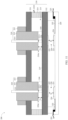
- a resonant cavity includes a piezoelectric ceramic 10, two substrates 11 and 11', two glass plates 12 and 12', and two collimators 13 and 13'.
- the glass plate 12 and the collimator 13 are respectively disposed on two sides of the substrate 11, and the glass plate 12' and the collimator 13' are respectively disposed on two sides of the substrate 11'.
- a side on which the glass plate 12 is disposed and that is of the substrate 11 is opposite to a side on which the glass plate 12' is disposed and that is of the substrate 11', there is a gap between the glass plate 12 and the glass plate 12', and the piezoelectric ceramic 10 encloses between the substrate 11 and the substrate 11', to form a resonant cavity 17 between the substrate 11 and the substrate 11'.
- the WDM optical signal enters the collimator 13 from an optical fiber 14, passes through the resonant cavity 17, then,, and the WDM optical signal is emitted into an optical fiber 15 from the collimator 13', and finally, is emitted into a receiving apparatus 16 through the optical fiber 15.
- the resonant cavity in the foregoing resonant cavity solution has a complex structure and a large volume, and this is not conducive to miniaturization development of an optical sub-assembly.
- Embodiments of this application provide a resonant cavity packaging structure, an optical performance monitor, and a communication device, where the resonant cavity packaging structure has a simple structure and a small volume, and this is conducive to miniaturization development of an optical sub-assembly.
- a first aspect of embodiments of this application provides a resonant cavity packaging structure, where the resonant cavity packaging structure includes an optical fiber sub-assembly, a fastening structure, and a support member.
- the optical fiber sub-assembly and the support member are disposed oppositely at two ends of the fastening structure.
- a first cavity is disposed in the fastening structure, an optical fiber is disposed in the optical fiber sub-assembly, the optical fiber sub-assembly penetrates into the fastening structure, and an optical fiber end face of the optical fiber is located in the first cavity.
- One end that is of the optical fiber sub-assembly and on which the optical fiber end face is disposed is a first end of the optical fiber sub-assembly, a second cavity is formed between the first end of the optical fiber sub-assembly and an inner wall that is of the first cavity and that is opposite to the first end of the optical fiber sub-assembly, and the second cavity is configured to provide resonance space for an optical signal emitted from the optical fiber.
- a receiving apparatus is disposed in the support member, the receiving apparatus corresponds to the second cavity, and the receiving apparatus is configured to receive an optical signal emitted from the fastening structure through the second cavity.
- the resonant cavity packaging structure in embodiments of this application has a simple structure and a small volume, and this is conducive to miniaturization development of an optical sub-assembly.
- the receiving apparatus is disposed in the support member, so that the optical signal emitted from the fastening structure can be received, and the optical signal emitted from the fastening structure can directly enter the receiving apparatus without passing through the collimator and the optical fiber.
- an insertion loss of the optical signal received by the resonant cavity packaging structure in embodiments of this application is smaller. In this way, an optical power of the optical signal received by the receiving apparatus can be increased. In addition, this can further reduce a size of the resonant cavity packaging structure and improve integration of the resonant cavity packaging structure.
- a high reflection coating is disposed on an inner wall that is of the fastening structure and that is opposite to the optical fiber end face; an orthographic projection that is of the high reflection coating and that is in a center axis direction of the optical fiber covers at least the optical fiber end face; and the second cavity is formed between the first end of the optical fiber sub-assembly and the high reflection coating.
- the high reflection coating is disposed on the inner wall that is of the fastening structure and that is opposite to the optical fiber end face. Because the high reflection coating has a high reflectivity, a reflectivity of the inner wall that is of the fastening structure and that is opposite to the optical fiber end face can be improved, that is, a reflectivity of a reflection wall of the second cavity is improved.
- a first lens is disposed on a surface that is of the fastening structure and that faces the support member; the first lens corresponds to the second cavity; the receiving apparatus is disposed opposite to a surface that is of the first lens and that is away from the fastening structure; and the first lens is configured to: couple the optical signal output from the fastening structure through the second cavity and then emit the coupled optical signal into the receiving apparatus.
- the first lens is disposed, and then the first lens corresponds to the second cavity and is disposed opposite to the receiving apparatus.
- the optical signal of a specific wavelength emitted from the second cavity can enter the receiving apparatus after passing through the first lens, and the first lens may couple the optical signal of a specific wavelength emitted from the second cavity and then the optical signal enters the receiving apparatus.
- an insertion loss can be reduced, and an optical power of the optical signal entering the receiving apparatus can be increased.
- a second lens is disposed on the optical fiber end face; the second cavity is formed between the second lens and the inner wall that is of the first cavity and that is opposite to the second lens; and the second lens is configured to couple the optical signal emitted from the optical fiber.
- the telescopic structure is disposed between the top wall and the bottom wall of the fastening structure, so that the distance between the top wall and the bottom wall of the fastening structure can be changed. Because both the first cavity and the second cavity are located between the top wall and the bottom wall of the fastening structure, the lengths of the first cavity and the second cavity in the direction from the top wall to the bottom wall can be changed by changing the length of the telescopic structure. In this way, the lengths of the first cavity and the second cavity may be changed, to change a wavelength of an optical signal filtered out by the resonant cavity packaging structure, so that the resonant cavity packaging structure can filter out optical signals of different specific wavelengths. This improves applicability of the resonant cavity packaging structure.
- the telescopic structure is a piezoelectric ceramic; and a first electrical pin is disposed on the piezoelectric ceramic, and the first electrical pin is configured to be electrically connected to a control circuit.
- a material of the telescopic structure is a thermosensitive material; and a size of the thermosensitive material varies with a temperature.
- At least one second electrical pin is disposed on an outer side of the support member; and each receiving apparatus corresponds to at least one second electrical pin, a part of second electrical pins is configured to be grounded, and a part of the second electrical pins is electrically connected to the receiving apparatus.
- the receiving apparatus is disposed, so that the optical signal emitted from the second cavity may be converted into the electrical signal.
- the second electrical pin is disposed, so that the electrical signal of the receiving apparatus may be led out to an outer side of the resonant cavity packaging structure, to help connect to another component.
- an internal line is disposed on the support member, and the internal line is configured to electrically connect the second electrical pin and the receiving apparatus.
- the internal line is disposed, so that the receiving apparatus is electrically connected to the second electrical pin.
- one end of the internal line is electrically connected to the second electrical pin, and the other end of the internal line is electrically connected to the receiving apparatus through a connecting line.
- the connecting line is a metal line.
- the connecting line is set as a metal line, so that conductivity between the receiving apparatus and the internal line can be improved.
- the metal line has good extensibility and good flexibility, so that connection stability between the receiving apparatus and the internal line can be ensured.
- the second electrical pin is a flexible circuit board or a metal pin.
- a material of the support member is ceramic.
- the material of the support member is set to be ceramic, so that a service life of the resonant cavity packaging structure can be prolonged because the ceramic has high mechanical strength, good abrasive resistance, and good corrosion resistance.
- the receiving apparatus is a photoelectric diode.
- the receiving apparatus is disposed as a photoelectric diode, so that the receiving apparatus can convert the optical signal into the electrical signal.
- At least one optical fiber is disposed in the optical fiber sub-assembly.
- the optical fiber sub-assembly further includes a ferrule and an outer tube; the ferrule encloses an outer side of the optical fiber, the outer tube encloses an outer side of the ferrule, and both a first end of the ferrule and the optical fiber end face are located in the first cavity; and the outer tube is located on an outer side of the fastening structure, and is fixedly connected to the fastening structure.
- the optical fiber sub-assembly is disposed as a structure including the ferrule and the outer tube.
- the ferrule may protect the optical fiber, enable the optical fiber to be fastened to the fastening structure through the ferrule, and enable the optical fiber end face to be located in the first cavity.
- the outer tube is disposed, to facilitate fastening of the optical fiber sub-assembly to one end of the fastening structure.
- a second aspect of embodiments of this application provides an optical performance monitor, including at least the resonant cavity packaging structure according to any one of the first aspect or the possible implementations of the first aspect.
- the resonant cavity packaging structure according to the first aspect is disposed. Because the resonant cavity packaging structure has a simple structure and a small volume, a volume of the optical performance monitor can be greatly reduced, and this is conducive to miniaturization development of an optical sub-assembly.
- a third aspect of embodiments of this application provides a communication device, including at least the optical performance monitor according to the second aspect, or including at least the resonant cavity packaging structure according to any one of the first aspect or the possible implementations of the first aspect.
- the resonant cavity packaging structure according to the first aspect or the optical performance monitor according to the second aspect is disposed, so that the communication device can have a function of monitoring quality of an indicator like an optical power, a wavelength, or an optical signal noise ratio (Optical Signal Noise Ratio, OSNR) of an optical signal, a volume of the communication device can be further reduced, and integration of the communication device can be further improved. This is conducive to miniaturization development of the communication device.
- OSNR optical Signal Noise Ratio
- position terms such as “front” and “back” are defined relative to illustrative positions of components in accompanying drawings. It should be understood that these direction terms are relative concepts and are used for descriptions and clarification of "relative to”, and may vary based on changes of the positions of the components in the accompanying drawings.
- Term "and/or” in embodiments of this application describes only an association relationship for describing associated objects and indicates that three relationships may exist.
- a and/or B may indicate the following three cases: Only A exists, both A and B exist, and only B exists.
- a character "/" in this specification generally indicates an "or" relationship between the associated objects.
- wavelength division network devices are increasingly widely used.
- an optical performance monitor usually needs to be disposed, to monitor quality of an indicator like an optical power, a wavelength, or an optical signal noise ratio of a wavelength division multiplexing optical signal, and the quality of the indicator is fed back to a system, to implement closed-loop monitoring.
- a micro-electro-mechanical system Micro-Electro-Mechanical System, MEMS
- MEMS Micro-Electro-Mechanical System
- a rotating angle range in the MEMS rotating mirror solution is limited, resulting in a limited WDM wavelength range that can be monitored. Therefore, a resonant cavity solution is proposed in the related technology.
- a resonant cavity in the related technology has a problem of a complex structure and a large volume, and this is not conducive to miniaturization development of an optical sub-assembly.
- embodiments of this application provide a resonant cavity packaging structure with a simple structure and a small volume, an optical performance monitor, and a communication device.
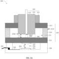
- FIG. 3A is a diagram of a structure of a resonant cavity packaging structure 200 according to an embodiment of this application. As shown in FIG. 3A , an embodiment of this application provides a resonant cavity packaging structure 200.
- the resonant cavity packaging structure 200 may include an optical fiber sub-assembly 230, a fastening structure 210, and a support member 220.
- the optical fiber sub-assembly 230 and the support member 220 are disposed oppositely at two ends of the fastening structure 210.
- a first cavity 213 is disposed in the fastening structure 210, the optical fiber sub-assembly 230 penetrates into the fastening structure 210, a first end 230a of the optical fiber sub-assembly 230 is located in the first cavity 213, and a second cavity 240 is formed between the first end 230a of the optical fiber sub-assembly 230 and an inner wall that is of the first cavity 213 and that is opposite to the first end 230a of the optical fiber sub-assembly 230.
- a receiving apparatus 221 is disposed in the support member 220, the receiving apparatus 221 corresponds to the optical fiber sub-assembly 230, and the receiving apparatus 221 is configured to receive an optical signal emitted from the inside of the fastening structure 210.
- the optical fiber sub-assembly 230 may include an optical fiber 231, a ferrule 232, and an outer tube 233, where the ferrule 232 encloses an outer side of the optical fiber 231, the outer tube 233 encloses an outer side of the ferrule 232, and both a first end of the ferrule 232 and an optical fiber end face 2311 of the optical fiber 231 are located at the first end 230a of the optical fiber sub-assembly 230, and are located in the first cavity 213.
- the outer tube 233 is located on an outer side of the fastening structure 210, and is fixedly connected to the fastening structure 210.
- a quantity of optical fibers 231 in the optical fiber sub-assembly 230 includes but is not limited to one shown in the figure. There is at least one optical fiber 231 in the optical fiber sub-assembly 230, and each optical fiber 231 may be packaged in a plastic sleeve (not shown in the figure), so that the optical fiber 231 can be bent without being broken.
- a plurality of optical fibers 231 may be disposed in the optical fiber sub-assembly 230 in a form of an optical fiber bundle (that is, a plurality of optical fibers form a bundle of optical fibers); or may be disposed in the optical fiber sub-assembly 230 in a form of an optical fiber ribbon (that is, a plurality of optical fibers are arranged in parallel); or certainly, may be disposed in the optical fiber sub-assembly 230 in a form of an optical fiber array (Fiber Array, FA).
- An arrangement form of the optical fiber in the optical fiber sub-assembly 230 is not specifically limited in embodiments, provided that the optical fiber 231 is disposed.
- the optical fiber 231 may be a multi-mode optical fiber or a single-mode optical fiber.
- a type of the optical fiber is not specifically limited in embodiments of this application.
- the optical fiber 231 may be fixedly connected to the ferrule 232 in a manner of bonding or welding, the ferrule 232 may be fixedly connected to the outer tube 233 in a manner of bonding or welding, the ferrule 232 may be fixedly connected to the fastening structure 210 in a manner of bonding or welding, and the outer tube 233 may be fixedly connected to the fastening structure 210 in a manner of bonding, welding, or the like.
- Connection manners between the optical fiber 231 and the ferrule 232, between the ferrule 232 and the outer tube 233, between the ferrule 232 and the fastening structure 210, and between the outer tube 233 and the fastening structure 210 are not specifically limited in embodiments.
- the ferrule 232 in the optical fiber sub-assembly 230 may be a ceramic ferrule 232, and the ceramic ferrule 232 may fasten the optical fiber 231, so that the optical fiber end face 2311 may directly extend into the first cavity 213.
- the resonant cavity packaging structure 200 in this embodiment may not need the collimator 13 and the glass plate 12, so that a volume of the resonant cavity packaging structure 200 can be greatly reduced.
- the ceramic ferrule 232 may further ensure communication quality of the optical fiber 231.
- the outer tube 233 in the optical fiber sub-assembly 230 may be a glass tube, and the glass tube has a good thermal stability and is not likely to deform. Therefore, it can be ensured that the resonant cavity packaging structure 200 is not likely to deform in use, to further prolong a service life of the resonant cavity packaging structure 200.
- the first end 230a of the optical fiber sub-assembly 230 and an inner wall that is of the fastening structure 210 and that is opposite to the first end 230a of the optical fiber sub-assembly 230 are parallel to each other, the first end 230a of the optical fiber sub-assembly 230 may be a plane or a curved surface, and the first end 230a of the optical fiber sub-assembly 230 has a high reflectivity.
- the inner wall that is of the fastening structure 210 and that is opposite to the first end 230a of the optical fiber sub-assembly 230 may be a plane or a curved surface, and the inner wall that is of the fastening structure 210 and that is opposite to the first end 230a of the optical fiber sub-assembly 230 has a high reflectivity and has a specific transmittance.
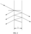
- a resonant cavity may be formed between two parallel lenses. After the optical signal passes through the resonant cavity, a part of the optical signal may be emitted from the resonant cavity, and a part of the optical signal oscillates in the resonant cavity. Therefore, an optical signal may be filtered out by using the resonant cavity. For example, an optical signal of which wavelength is an integer multiple of a cavity length L of the resonant cavity may be filtered out.
- the resonant cavity may be formed between the first end 230a of the optical fiber sub-assembly 230 and the inner wall that is of the fastening structure 210 and that is opposite to the first end 230a of the optical fiber sub-assembly 230, that is, the second cavity 240 may be used as the resonant cavity, that is, the second cavity 240 may provide resonance space for the optical signal entering the second cavity 240.
- one end that is of the second cavity 240 and that is close to the optical fiber sub-assembly 230 is used as an input end of the second cavity 240
- one end that is of the second cavity 240 and that is close to the fastening structure 210 is used as an output end of the second cavity 240
- a distance between a top wall 211 and a bottom wall 212 of the fastening structure 210 is used as a height direction of the resonant cavity packaging structure 200.
- the input end and the output end of the second cavity 240 each have a reflection function
- the output end of the second cavity 240 further has a transmission function, so that an optical signal of a specific wavelength is output after the optical signal oscillates in the second cavity 240.
- the optical signals When optical signals are input into the optical fiber 231 in the optical fiber sub-assembly 230, the optical signals may be emitted into the second cavity 240 from the optical fiber end face 2311, and after oscillation is generated between two end faces of the second cavity 240, optical signals that are of a specific wavelength and of which propagation directions, frequencies and phases are the same are obtained, and then are emitted from a side that is of the fastening structure 210 and that is opposite to the first end 230a of the optical fiber sub-assembly 230, that is, the optical signals of a specific wavelength may be obtained after the optical signals of the optical fiber sub-assembly 230 pass through the second cavity 240.
- the optical signal of a specific wavelength enters the receiving apparatus 221, and the receiving apparatus 221 may convert the received optical signal of a specific wavelength into an electrical signal.
- the resonance space of the optical signal may occupy the entire second cavity 240, or may occupy only a part of the second cavity 240.
- the optical signal oscillates only in a part that is of the cavity and that is formed between the optical fiber end face 2311 and the inner wall that is of the fastening structure 210 and that is opposite to the optical fiber end face 2311. Therefore, the second cavity 240 may be used as a resonant cavity of the resonant cavity packaging structure 200, and a third cavity 250 formed between the optical fiber end face 2311 and the inner wall that is of the fastening structure 210 and that is opposite to the optical fiber end face 2311 may also be used as a resonant cavity.
- a specific range of the resonant cavity is not specifically limited in embodiments of this application, provided that the optical signal may oscillate in the second cavity 240, and the optical signal of a specific wavelength may be output from the output end of the second cavity 240.
- the fastening structure 210 may include the top wall 211, the bottom wall 212, and a telescopic structure 214.
- the top wall 211 and the bottom wall 212 are disposed opposite to each other, the telescopic structure 214 is enclosed between the top wall 211 and the bottom wall 212, one end of the telescopic structure 214 is fixedly connected to the top wall 211, and the other end of the telescopic structure 214 is fixedly connected to the bottom wall 212, so that the first cavity 213 is formed among the top wall 211, the bottom wall 212, and the telescopic structure 214.
- a connection manner between the telescopic structure 214 and each of the top wall 211 and the bottom wall 212 may be a bonding manner, a welding manner, a riveting manner, a fastener connection manner, or the like.
- a fastening manner between the telescopic structure 214 and each of the top wall 211 and the bottom wall 212 is not specifically limited.
- a through hole (not shown in the figure) may be provided on the top wall 211 of the fastening structure 210, the first end 230a of the optical fiber sub-assembly 230 penetrates into the through hole of the top wall 211, and the outer tube 233 of the optical fiber sub-assembly 230 is fastened to the outer side of the top wall 211, so that the first end 230a of the optical fiber sub-assembly 230 may be located in the first cavity 213.
- the support member 220 is disposed on an outer side of the bottom wall 212 of the fastening structure 210, the receiving apparatus 221 is disposed in the support member 220, the receiving apparatus 221 corresponds to the optical fiber sub-assembly 230, and the receiving apparatus 221 is configured to receive the optical signal emitted from the bottom wall 212 of the fastening structure 210.
- a through hole may also be provided on the bottom wall 212 of the fastening structure 210, the first end 230a of the optical fiber sub-assembly 230 penetrates into the through hole of the bottom wall 212, and the outer tube 233 of the optical fiber sub-assembly 230 is fastened to an outer side of the bottom wall 212, so that the first end 230a of the optical fiber sub-assembly 230 may be located in the first cavity 213.
- the support member 220 is disposed on the outer side of the top wall 211 of the fastening structure 210, the receiving apparatus 221 is disposed in the support member 220, the receiving apparatus 221 corresponds to the optical fiber sub-assembly 230, and the receiving apparatus 221 is configured to receive the optical signal emitted from the top wall 211 of the fastening structure 210.
- optical fiber sub-assembly 230 is disposed on the top wall 211 and the support member 220 is disposed on the bottom wall 212 for description.
- the first end 230a of the optical fiber sub-assembly 230 may extend out of the top wall 211 for a distance (as shown in a position shown in FIG. 3A ).
- the first end 230a of the optical fiber sub-assembly 230 may alternatively be flush with a surface that is of the top wall 211 and that faces the first cavity 213.
- the first cavity 213 is the second cavity 240.
- first end 230a of the optical fiber sub-assembly 230 may alternatively be located in an aperture of the through hole. Therefore, a position of the first end 230a of the optical fiber sub-assembly 230 may be specifically set based on a specific requirement, and the position of the first end 230a of the optical fiber sub-assembly 230 is not specifically limited in embodiments.
- a disposing position of the first end 230a of the optical fiber sub-assembly 230 is not specifically limited in embodiments of this application, provided that the optical fiber end face 2311 may be located in the first cavity 213.
- the top wall 211 and the bottom wall 212 of the fastening structure 210 may be glass plate structures.
- the glass plate structure has a high reflectivity and a specific transmittance, so that a requirement of the resonant cavity can be met.
- the glass plate structure is stable and is not likely to deform, so that a service life of the resonant cavity packaging structure 200 can be effectively prolonged.
- the top wall 211 and the bottom wall 212 may be glass plates with a small expansion coefficient or zero expansion glass plates. In this way, it can be ensured that a structure of the fastening structure 210 is more stable, and the service life of the resonant cavity packaging structure 200 is further prolonged.
- the receiving apparatus 221 is configured to: receive the optical signal emitted from the bottom wall 212 of the fastening structure 210 through the second cavity 240, and convert the optical signal into an electrical signal.
- the receiving apparatus 221 may be a photoelectric diode.
- the receiving apparatus 221 is disposed in the support member 220, so that the optical signal emitted from the fastening structure 210 can be received, and the optical signal emitted from the fastening structure can directly enter the receiving apparatus without passing through a collimator and an optical fiber.
- an insertion loss of the optical signal received by the resonant cavity packaging structure 200 in embodiments of this application is smaller. In this way, an optical power of the optical signal received by the receiving apparatus 221 can be increased. In addition, this can further reduce a size of the resonant cavity packaging structure 200 and improve integration of the resonant cavity packaging structure 200.
- At least one second electrical pin 223 is disposed on an outer side of the support member 220.
- One receiving apparatus 221 corresponds to the at least one second electrical pin 223, a part of the second electrical pins 223 is configured to be grounded, and a part of the second electrical pins 223 is electrically connected to the receiving apparatus 221.
- the plurality of receiving apparatuses 221 may share one second electrical pin 223, or one grounded second electrical pin 223 may be disposed to each receiving apparatus 221.
- a quantity of second electrical pins 223 is not specifically limited in embodiments.
- the receiving apparatus 221 is disposed, so that the optical signal emitted from the second cavity 240 may be converted into the electrical signal.
- the second electrical pin 223 is disposed, so that the electrical signal of the receiving apparatus 221 may be led out to an outer side of the resonant cavity packaging structure 200, to help connect to another component.
- an internal line 222 is disposed on the support member 220, and the internal line 222 is configured to electrically connect the second electrical pin 223 and the receiving apparatus 221.
- One end of the internal line 222 is electrically connected to the second electrical pin 223, and the other end of the internal line 222 is electrically connected to the receiving apparatus 221 through a connecting line 224.
- the connecting line 224 is a metal line.
- the receiving apparatus 221 and the internal line 222 may alternatively be welded and connected through a solder ball 227 in a flip chip (Flip chip) manner, where the solder ball 227 may be a tin ball, a metal ball, or the like, provided that the solder ball is conductive and is convenient for welding.
- the connecting line 224 does not need to be disposed, so that a part of lines can be saved, and costs can be reduced.
- a structure of the support member can be simpler.
- a connection manner between the receiving apparatus 221 and the internal line 222 is not specifically limited in embodiments of this application.
- the internal line 222 is disposed, so that the receiving apparatus 221 is electrically connected to the second electrical pin 223.
- the connecting line 224 is disposed as a metal line, so that conductivity between the receiving apparatus 221 and the internal line 222 can be improved.
- the metal line has good scalability and flexibility, so that connection stability between the receiving apparatus 221 and the internal line 222 can be ensured.
- the second electrical pin 223 may be a flexible circuit board, a metal pin, or the like, and the second electrical pin 223 may be fixedly connected to the support member 220 in a manner of welding or the like.
- the support member 220 may be fixedly connected to the fastening structure 210 in a manner of bonding, welding, or the like.
- a connection manner between the support member 220 and the fastening structure 210 is not specifically limited in embodiments of this application.
- a material of the support member 220 may be ceramic.
- the material of the support member 220 is set to be ceramic, so that the service life of the resonant cavity packaging structure 200 can be prolonged because the ceramic has high mechanical strength, good abrasive resistance, and good corrosion resistance.
- the material of the support member 220 may alternatively be a metal material.
- a first lens 225 may be further disposed on a surface that is of the bottom wall 212 of the fastening structure 210 and that is close to the support member 220.
- the first lens 225 corresponds to the second cavity 240.
- the receiving apparatus 221 is disposed opposite to a surface that is of the first lens 225 and that is away from the fastening structure 210.
- the first lens 225 is configured to: couple the optical signal output from the fastening structure 210 through the second cavity 240, and then emit the optical signal into the receiving apparatus 221.
- an incident position is disposed on a surface that is of the receiving apparatus 221 and that faces the first lens 225.
- the optical signal obtained through coupling by the first lens 225 is emitted into the receiving apparatus 221 at the incident position.
- a height of the gap may be h, and the gap 226 is used to provide coupling space for the optical signal passing through the first lens 225.
- the first lens 225 is disposed, and the first lens 225 corresponds to the second cavity 240 and is disposed opposite to the receiving apparatus 221. In this way, the optical signal of a specific wavelength emitted through the second cavity 240 can pass through the first lens 225 and then enter the receiving apparatus 221.
- the first lens 225 is configured to couple the optical signal of a specific wavelength emitted from the second cavity 240 and then the optical signal enters the receiving apparatus 221. In this way, an insertion loss can be reduced, and the optical power of the optical signal entering the receiving apparatus 221 can be increased.
- the gap 226h is disposed between the first lens 225 and the receiving apparatus 221, so that the coupling space can be provided for the optical signal passing through the first lens 225. This improves the optical power of the optical signal entering the receiving apparatus 221.
- the first lens 225 may be a common lens, and the first lens 225 may be fastened to the bottom wall 212 of the fastening structure 210 in a manner of bonding, integral forming, or the like.
- the first lens 225 may alternatively be disposed on the receiving apparatus 221.
- the receiving apparatus 221 comes with the first lens 225.
- the first lens 225 may be disposed on the receiving apparatus 221 in a manner of welding, bonding, or the like.
- the first lens 225 may alternatively be fastened to the receiving apparatus 221 by disposing another connecting member.
- a connection manner between the first lens 225 and the receiving apparatus 221 is not specifically limited in embodiments.
- the first lens 225 and the bottom wall 212 of the fastening structure 210 may be in gap cooperation or contact connection.
- a cooperation relationship between the first lens 225 and the bottom wall 212 of the fastening structure 210 is not specifically limited in embodiments.
- the first lens 225 is directly disposed on the receiving apparatus 221, so that the structure of the fastening structure 210 can be simplified. In addition, during assembly, the first lens 225 does not need to be assembled with the bottom wall 212 of the fastening structure 210, and only needs to be mounted together with the receiving apparatus 221 in the support member 220. In this way, assembly time can be reduced, and production efficiency can be improved.
- a trans-impedance amplifier Trans-impedance Amplifier, TIA
- the receiving apparatus 221 may be electrically connected to the TIA, and the TIA may be electrically connected to the internal line 222.
- the trans-impedance amplifier is disposed in the support member 220, so that the electrical signal converted by the receiving apparatus 221 may be amplified, and then an amplified signal enters the internal line 222 of the support member 220 and then be led out through the second electrical pin 223.
- another component may be further disposed in the support member 220, so that the receiving apparatus 221, the internal line 222, and the second electrical pin 223 are better connected. This is not specifically limited in embodiments of this application.
- a range between two adjacent resonant frequencies of the resonant cavity namely, a free spectral range (Free Spectral Range, FSR)
- FSR Free Spectral Range
- FSR C/2nL, where C is a light velocity in a vacuum; n is an intermediate medium refractive index, and if the intermediate medium is air, n is approximately 1; and L is a distance between two end faces of the resonant cavity, namely, a cavity length of the resonant cavity.
- the position of the interference peak may be changed by changing the cavity length L of the resonant cavity, to implement the function of the tunable filter.
- the optical fiber sub-assembly 230 is disposed on the top wall 211 or the bottom wall 212 of the fastening structure 210, and the telescopic structure 214 is disposed between the top wall 211 and the bottom wall 212 of the fastening structure 210.
- a height L 1 of the second cavity 240 (namely, the cavity length of the resonant cavity) may be changed by changing a height of the telescopic structure 214.
- the cavity length of the resonant cavity is changed.
- the resonant cavity packaging structure 200 may implement the function of the tunable filter, and a same resonant cavity packaging structure 200 may be used to filter out a plurality of optical signals of different wavelengths.
- the telescopic structure 214 may be a piezoelectric ceramic, where a first electrical pin 2141 is disposed on the piezoelectric ceramic, and the first electrical pin 2141 is configured to be electrically connected to a control circuit.
- the telescopic structure 214 is disposed as a piezoelectric ceramic. Because the piezoelectric ceramic has good frequency stability, high frequency accuracy, and a wide applicable frequency range, and the piezoelectric ceramic is small in volume, does not absorb moisture, has a long service life, and has good anti-interference performance, stability and anti-interference performance of the resonant cavity packaging structure 200 can be improved.
- a material of the telescopic structure 214 may alternatively be a thermosensitive material.
- a size of the thermosensitive material varies with a temperature. For example, a higher temperature indicates a larger volume, or a lower temperature indicates a larger volume. In this way, a size of the telescopic structure 214 may be changed by changing the temperature, so that the height of the second cavity 240 is changed.
- the telescopic structure 214 may alternatively be a micro-electro-mechanical system or another telescopic mechanical structure, for example, a structure like a telescopic tube. A specific structure of the telescopic structure 214 is not specifically limited in embodiments of this application.
- a high reflection coating 215 may be further disposed at the output end of the second cavity 240, namely, the bottom wall 212 of the fastening structure 210, where an orthographic projection that is of the high reflection coating 215 and that is in the center axis direction of the optical fiber 231 covers at least the optical fiber end face 2311, so that the second cavity 240 is formed between the high reflection coating 215 and the first end 230a of the optical fiber sub-assembly 230.
- the high reflection coating 215 is disposed on the inner wall that is of the fastening structure 210 and that is opposite to the optical fiber end face 2311. Because the high reflection coating 215 has a high reflectivity, a reflectivity of the output end of the second cavity 240 can be improved.
- R is the reflectivity of the resonant cavity. It can be learned from the foregoing formula that a larger R indicates a narrower ⁇ F, and a larger fineness of the obtained optical signal.
- a value range of R may be any value in 0 to 1.
- a specific value of R is not specifically limited.
- the high reflection coating 215 is disposed on the bottom wall 212 of the fastening structure 210, so that the reflectivity of the output end of the second cavity 240 can be improved, and a bandwidth of the optical signal emitted through the second cavity 240 can be reduced, so that the optical signal emitted through the second cavity 240 has higher fineness, that is, an error of the optical signal of the specific wavelength filtered out through the second cavity 240 is reduced.
- the high reflection coating 215 may cover the entire surface that faces the first cavity 213 and that is of the bottom wall 212 of the fastening structure 210. This facilitates processing.
- the high reflection coating 215 may alternatively be disposed only on a part that is of the bottom wall 212 and that is opposite to the first end 230a of the optical fiber sub-assembly 230, so that a part of the high reflection coating 215 can be saved.
- the high reflection coating 215 may alternatively be disposed on a part that is of the bottom wall 212 and that is opposite to the optical fiber end face 2311, namely, one end that is of the third cavity 250 and that is located on the bottom wall 212 of the fastening structure 210.
- a disposing range of the high reflection coating 215 is not specifically limited in embodiments of this application, and any technical solution of disposing the high reflection coating 215 falls within a protection scope of technical solutions of this application.
- the high reflection coating 215 may be fastened to the bottom wall 212 of the fastening structure 210 in a manner of bonding, coating, or the like.
- a connection manner between the high reflection coating 215 and the fastening structure 210 is not specifically limited in embodiments of this application.
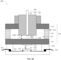
- a second lens 234 may be further disposed at the first end of the optical fiber end face 2311.
- the second cavity 240 is formed between the second lens 234 and the inner wall that is of the first cavity 213 and that is opposite to the second lens 234.
- the second lens 234 is configured to couple the optical signal emitted from the optical fiber 231.
- the optical signal emitted from the optical fiber end face 2311 may be coupled and then enters the second cavity 240.
- the optical signal emitted from the optical fiber end face 2311 may be resonated in narrower space.
- tolerances of the first lens 225 and the receiving apparatus 221 can be increased without increasing widths of the first lens 225 and the receiving apparatus 221. This can improve the optical power of the optical signal received by the receiving apparatus 221, and further improve efficiency of the resonant cavity packaging structure 200.
- the second lens 234 may be fixedly connected to the first end 230a of the optical fiber sub-assembly 230 in a manner of bonding or the like, and the second lens 234 at least completely covers the optical fiber end face 2311 of the optical fiber 231. In this way, the optical signal emitted from the optical fiber 231 can be coupled.
- a refractive index and another parameter of the second lens 234 are not specifically limited. These may be specifically limited in a specific case.
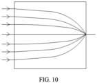
- the second lens 234 may be a self-focusing lens.
- the self-focusing lens may enable the optical signal to be coupled in the self-focusing lens. In this way, an insertion loss generated when the optical signal is propagated in a medium can be reduced, to further improve efficiency of the optical signal received by the receiving apparatus 221.
- the second lens 234 is designed as the self-focusing lens, so that the insertion loss of the optical signal emitted from the optical fiber end face 2311 can be reduced, and further the efficiency of the resonant cavity packaging structure 200 can be improved.
- the second lens 234 is designed as the self-focusing lens, so that the height L 1 of the second cavity 240 can be further reduced, and further the volume of the resonant cavity packaging structure 200 can be reduced.
- a value of the height L 1 of the second cavity 240 is at a micrometer level, and therefore, the height of the second cavity 240 is very small.
- the height shown in the figure does not indicate an actual height. Therefore, the structure in the figure does not limit the protection scope of embodiments of this application.
- FIG. 11 there may be a plurality of optical fiber sub-assemblies 230 and a plurality of receiving apparatuses 221 (two optical fiber sub-assemblies 230 and two receiving apparatuses 221 are shown in the figure).
- One optical fiber sub-assembly 230 corresponds to one receiving apparatus 221.
- the plurality of optical fiber sub-assemblies 230 are disposed on a same side of the fastening structure 210 at intervals, and an optical fiber end face 2311 of each optical fiber sub-assembly 230 is located in the first cavity 213.
- a second cavity 240 is formed between a first end 230a of each optical fiber sub-assembly 230 and the inner wall that is of the first cavity 213 and that is opposite to the first end 230a of the optical fiber sub-assembly 230.
- the plurality of optical fiber sub-assemblies 230 and the plurality of the receiving apparatus 221 are disposed, so that a plurality of second cavities 240 can be disposed in the fastening structure 210.
- the resonant cavity packaging structure 200 can simultaneously perform filtering on optical signals sent by the plurality of optical fiber sub-assemblies 230. This can improves the efficiency of the resonant cavity packaging structure 200 on a premise that the volume of the resonant cavity packaging structure 200 is not greatly affected.
- the optical fiber sub-assembly 230 may be the optical fiber sub-assembly 230 without the second lens 234, or may be the optical fiber sub-assembly 230 with the second lens 234; the high reflection coating 215 may be disposed on the bottom wall 212 of the fastening structure 210, or the high reflection coating 215 may not be disposed; and the first lens 225 may be disposed in the support member 220, or the first lens 225 may not be disposed. This may be specifically disposed in a specific case.
- heights L 1 and L 2 of different second cavities 240 located in a same resonant cavity packaging structure 200 are the same, so that the resonant cavity packaging structure 200 can filter out optical signals of a same specific wavelength.
- the heights L 1 and L 2 of different second cavities 240 in a same resonant cavity packaging structure 200 may alternatively be set to different values. This may be specifically set in a specific case, and is not specifically limited in embodiments.
- the quantity of second electrical pins 223 on the support member 220 needs to correspond to a quantity of receiving apparatuses 221, so that an electrical signal of each receiving apparatus 221 can be led out.
- a second aspect of embodiments of this application provides an optical performance monitor, where the optical performance monitor may include the resonant cavity packaging structure 200 according to the first aspect.
- the optical performance monitor may be configured to measure quality of an indicator like an optical power, a wavelength, or an OSNR of a WDM optical signal, and a measurement result is fed back to the system, to implement closed-loop monitoring.
- the optical performance monitor is configured to monitor the WDM, ROADM, and OA in the system.
- the resonant cavity packaging structure 200 is disposed. Because the resonant cavity packaging structure 200 has a simple structure and a small volume, a volume of the optical performance monitor can be greatly reduced, and this is conducive to miniaturization development of an optical sub-assembly.
- a third aspect of embodiments of this application provides a communication device, including at least the resonant cavity packaging structure 200 according to the first aspect or the optical performance monitor according to the second aspect.
- the resonant cavity packaging structure 200 according to the first aspect or the optical performance monitor according to the second aspect is disposed, so that the communication device can have a function of monitoring quality of an indicator like an optical power, a wavelength, or an optical signal noise ratio (Optical Signal Noise Ratio, OSNR) of an optical signal, a volume of the communication device can be further reduced, and integration of the communication device can be further improved. This is conducive to miniaturization development of the communication device.
- OSNR optical signal Noise Ratio
- the communication device may be a board or a wavelength division network device.
- the wavelength division network device may be an optical transport network (Optical Transimmision Network, OTN) device
- the OTN device may be a dense wavelength division multiplexing (Dense Wavelength Division Multiplexing, DWDM) device, an optical add/drop multiplexer (opticaladd-dropmultiplexer, OADM), an optical crossconnect switch, an optical amplifier device, or an optical control device.
- OTN optical transport network
- DWDM dense wavelength division multiplexing
- OADM optical add/drop multiplexer
- mounting should be understood broadly, which, for example, may be a fixed connection, or may be an indirect connection by using a medium, or may be an internal communication between two components, or may be an interactive relationship between two components.
- connection should be understood broadly, which, for example, may be a fixed connection, or may be an indirect connection by using a medium, or may be an internal communication between two components, or may be an interactive relationship between two components.
Landscapes
- Physics & Mathematics (AREA)
- Engineering & Computer Science (AREA)
- Computer Networks & Wireless Communication (AREA)
- Signal Processing (AREA)
- General Physics & Mathematics (AREA)
- Optics & Photonics (AREA)
- Electromagnetism (AREA)
- Optical Couplings Of Light Guides (AREA)
Applications Claiming Priority (2)
| Application Number | Priority Date | Filing Date | Title |
|---|---|---|---|
| CN202210608273.9A CN117200878A (zh) | 2022-05-31 | 2022-05-31 | 谐振腔封装结构、光信道监测模块以及通信设备 |
| PCT/CN2023/078492 WO2023231477A1 (zh) | 2022-05-31 | 2023-02-27 | 谐振腔封装结构、光信道监测模块以及通信设备 |
Publications (2)
| Publication Number | Publication Date |
|---|---|
| EP4518191A1 true EP4518191A1 (de) | 2025-03-05 |
| EP4518191A4 EP4518191A4 (de) | 2025-08-13 |
Family
ID=88982403
Family Applications (1)
| Application Number | Title | Priority Date | Filing Date |
|---|---|---|---|
| EP23814676.5A Pending EP4518191A4 (de) | 2022-05-31 | 2023-02-27 | Resonanzhohlraumverpackungsstruktur, modul zur überwachung eines optischen kanals und kommunikationsvorrichtung |
Country Status (3)
| Country | Link |
|---|---|
| EP (1) | EP4518191A4 (de) |
| CN (1) | CN117200878A (de) |
| WO (1) | WO2023231477A1 (de) |
Families Citing this family (1)
| Publication number | Priority date | Publication date | Assignee | Title |
|---|---|---|---|---|
| CN119148309B (zh) * | 2024-09-24 | 2025-09-30 | 中国电子科技集团公司第三十八研究所 | 光垂直耦合的电光调制芯片与控制芯片共封装置 |
Family Cites Families (12)
| Publication number | Priority date | Publication date | Assignee | Title |
|---|---|---|---|---|
| WO1985002469A1 (en) * | 1983-11-28 | 1985-06-06 | British Telecommunications Plc | Optical filters |
| AU572330B2 (en) * | 1984-04-06 | 1988-05-05 | Gec-Marconi Limited | Fabricating optical sensing devices |
| US5666225A (en) * | 1996-02-26 | 1997-09-09 | Jds Fitel Inc. | Multi-pass etalon filter |
| US6438288B1 (en) * | 2000-12-15 | 2002-08-20 | Lightap | Tunable optical filter system |
| JP2005510756A (ja) * | 2001-11-28 | 2005-04-21 | アイギス セミコンダクター インコーポレイテッド | 電気光学構成部品用パッケージ |
| US7255487B1 (en) * | 2006-10-24 | 2007-08-14 | Choi Youngmin A | Simple fiber optic packaged filter |
| US7911623B2 (en) * | 2007-08-07 | 2011-03-22 | Xerox Corporation | Fabry-Perot piezoelectric tunable filter |
| EP2857876B1 (de) * | 2011-08-11 | 2020-07-08 | Ludwig-Maximilians-Universität München | Abstimmbarer VCSEL |
| WO2016169023A1 (zh) * | 2015-04-23 | 2016-10-27 | 北京航空航天大学 | 一种单分束器透射式光子晶体光纤谐振腔 |
| CN104776841B (zh) * | 2015-04-27 | 2017-10-27 | 浙江大学 | 谐振式光纤陀螺系统小型化集成装置及其方法 |
| CN106672887B (zh) * | 2016-12-29 | 2018-05-01 | 武汉理工大学 | 一种基于碳化硅光纤f-p谐振腔的振动加速度传感装置 |
| CN106549295B (zh) * | 2017-01-24 | 2019-02-26 | 厦门大学 | 一种光学谐振腔耦合系统的封装结构和方法 |
-
2022
- 2022-05-31 CN CN202210608273.9A patent/CN117200878A/zh active Pending
-
2023
- 2023-02-27 EP EP23814676.5A patent/EP4518191A4/de active Pending
- 2023-02-27 WO PCT/CN2023/078492 patent/WO2023231477A1/zh not_active Ceased
Also Published As
| Publication number | Publication date |
|---|---|
| WO2023231477A1 (zh) | 2023-12-07 |
| EP4518191A4 (de) | 2025-08-13 |
| CN117200878A (zh) | 2023-12-08 |
Similar Documents
| Publication | Publication Date | Title |
|---|---|---|
| US6558046B2 (en) | Optical wavelength division multiplexer and/or demultiplexer with mechanical strain relief | |
| CN203301489U (zh) | 具有多路波长通道的光发射器件、光接收器件及光模块 | |
| CN105929491B (zh) | 与单根光纤通信的双向光学组件及配备该组件的光收发器 | |
| JP5313983B2 (ja) | 光モジュール | |
| KR100640421B1 (ko) | 다파장용 광소자 모듈 | |
| JP2004233484A (ja) | 光モジュール | |
| KR20050079198A (ko) | 양방향 광송수신기 | |
| EP4518191A1 (de) | Resonanzhohlraumverpackungsstruktur, modul zur überwachung eines optischen kanals und kommunikationsvorrichtung | |
| CN103270443B (zh) | 光学模块及其制造方法 | |
| US12272928B2 (en) | Optical transmission module, optical transmission-reception module and optical module | |
| KR20050029083A (ko) | 더블유디엠 광커플러가 내장된 트라이플렉서 광모듈 | |
| CN223065560U (zh) | 一种窄带单纤四向合波光器件 | |
| JP6804698B1 (ja) | 集積光モジュール | |
| CN209560137U (zh) | 一种单光纤双向光收发组件 | |
| JP2004271803A (ja) | 光導波路装置及びそれを用いた光システム | |
| CN115343810B (zh) | 盒型封装光收发器件 | |
| KR101741039B1 (ko) | 양방향 광송수신 모듈 | |
| KR20030032774A (ko) | 단일 광섬유를 통한 광신호 송,수신 기능을 갖는 양방향성 광모듈 | |
| EP1816501B1 (de) | Optische Demultiplex-Vorrichtung | |
| CN112444924A (zh) | 具有整合的光学配置以偏移输出光路径的定位元件 | |
| JP2004361660A (ja) | アレイ導波路型波長分波素子 | |
| KR100465650B1 (ko) | 파장 다중 분할 커플러 장치를 이용한 양방향 광모듈 | |
| CN115220151B (zh) | 基于微环谐振腔游标效应硅基光波导解调器件及方法 | |
| KR100513846B1 (ko) | 포토닉크리스탈을 이용한 양방향 광 송수신기 | |
| KR100480304B1 (ko) | 양방향 광송수신기 및 이를 이용한 양방향 광송수신기 모듈 |
Legal Events
| Date | Code | Title | Description |
|---|---|---|---|
| STAA | Information on the status of an ep patent application or granted ep patent |
Free format text: STATUS: THE INTERNATIONAL PUBLICATION HAS BEEN MADE |
|
| PUAI | Public reference made under article 153(3) epc to a published international application that has entered the european phase |
Free format text: ORIGINAL CODE: 0009012 |
|
| STAA | Information on the status of an ep patent application or granted ep patent |
Free format text: STATUS: REQUEST FOR EXAMINATION WAS MADE |
|
| 17P | Request for examination filed |
Effective date: 20241128 |
|
| AK | Designated contracting states |
Kind code of ref document: A1 Designated state(s): AL AT BE BG CH CY CZ DE DK EE ES FI FR GB GR HR HU IE IS IT LI LT LU LV MC ME MK MT NL NO PL PT RO RS SE SI SK SM TR |
|
| A4 | Supplementary search report drawn up and despatched |
Effective date: 20250714 |
|
| RIC1 | Information provided on ipc code assigned before grant |
Ipc: H04B 10/07 20130101AFI20250708BHEP Ipc: H01S 3/08 20230101ALI20250708BHEP Ipc: G02B 6/293 20060101ALI20250708BHEP Ipc: G02B 6/42 20060101ALI20250708BHEP Ipc: H04B 10/079 20130101ALI20250708BHEP Ipc: H04J 14/02 20060101ALI20250708BHEP |
|
| DAV | Request for validation of the european patent (deleted) | ||
| DAX | Request for extension of the european patent (deleted) |