EP4518201A1 - Procédé et dispositif de détermination d'état d'indication de configuration - Google Patents
Procédé et dispositif de détermination d'état d'indication de configuration Download PDFInfo
- Publication number
- EP4518201A1 EP4518201A1 EP22939032.3A EP22939032A EP4518201A1 EP 4518201 A1 EP4518201 A1 EP 4518201A1 EP 22939032 A EP22939032 A EP 22939032A EP 4518201 A1 EP4518201 A1 EP 4518201A1
- Authority
- EP
- European Patent Office
- Prior art keywords
- channel
- tci states
- tci
- transmission
- pusch
- Prior art date
- Legal status (The legal status is an assumption and is not a legal conclusion. Google has not performed a legal analysis and makes no representation as to the accuracy of the status listed.)
- Pending
Links
Images

Classifications
-
- H—ELECTRICITY
- H04—ELECTRIC COMMUNICATION TECHNIQUE
- H04L—TRANSMISSION OF DIGITAL INFORMATION, e.g. TELEGRAPHIC COMMUNICATION
- H04L1/00—Arrangements for detecting or preventing errors in the information received
- H04L1/0001—Systems modifying transmission characteristics according to link quality, e.g. power backoff
- H04L1/0023—Systems modifying transmission characteristics according to link quality, e.g. power backoff characterised by the signalling
-
- H—ELECTRICITY
- H04—ELECTRIC COMMUNICATION TECHNIQUE
- H04L—TRANSMISSION OF DIGITAL INFORMATION, e.g. TELEGRAPHIC COMMUNICATION
- H04L5/00—Arrangements affording multiple use of the transmission path
- H04L5/003—Arrangements for allocating sub-channels of the transmission path
- H04L5/0053—Allocation of signalling, i.e. of overhead other than pilot signals
-
- H—ELECTRICITY
- H04—ELECTRIC COMMUNICATION TECHNIQUE
- H04L—TRANSMISSION OF DIGITAL INFORMATION, e.g. TELEGRAPHIC COMMUNICATION
- H04L1/00—Arrangements for detecting or preventing errors in the information received
- H04L1/0001—Systems modifying transmission characteristics according to link quality, e.g. power backoff
- H04L1/0036—Systems modifying transmission characteristics according to link quality, e.g. power backoff arrangements specific to the receiver
-
- H—ELECTRICITY
- H04—ELECTRIC COMMUNICATION TECHNIQUE
- H04L—TRANSMISSION OF DIGITAL INFORMATION, e.g. TELEGRAPHIC COMMUNICATION
- H04L5/00—Arrangements affording multiple use of the transmission path
-
- H—ELECTRICITY
- H04—ELECTRIC COMMUNICATION TECHNIQUE
- H04L—TRANSMISSION OF DIGITAL INFORMATION, e.g. TELEGRAPHIC COMMUNICATION
- H04L5/00—Arrangements affording multiple use of the transmission path
- H04L5/0001—Arrangements for dividing the transmission path
- H04L5/0014—Three-dimensional division
- H04L5/0023—Time-frequency-space
-
- H—ELECTRICITY
- H04—ELECTRIC COMMUNICATION TECHNIQUE
- H04L—TRANSMISSION OF DIGITAL INFORMATION, e.g. TELEGRAPHIC COMMUNICATION
- H04L5/00—Arrangements affording multiple use of the transmission path
- H04L5/003—Arrangements for allocating sub-channels of the transmission path
- H04L5/0044—Allocation of payload; Allocation of data channels, e.g. PDSCH or PUSCH
-
- H—ELECTRICITY
- H04—ELECTRIC COMMUNICATION TECHNIQUE
- H04L—TRANSMISSION OF DIGITAL INFORMATION, e.g. TELEGRAPHIC COMMUNICATION
- H04L5/00—Arrangements affording multiple use of the transmission path
- H04L5/0091—Signalling for the administration of the divided path, e.g. signalling of configuration information
- H04L5/0094—Indication of how sub-channels of the path are allocated
-
- H—ELECTRICITY
- H04—ELECTRIC COMMUNICATION TECHNIQUE
- H04W—WIRELESS COMMUNICATION NETWORKS
- H04W72/00—Local resource management
- H04W72/20—Control channels or signalling for resource management
- H04W72/21—Control channels or signalling for resource management in the uplink direction of a wireless link, i.e. towards the network
-
- H—ELECTRICITY
- H04—ELECTRIC COMMUNICATION TECHNIQUE
- H04W—WIRELESS COMMUNICATION NETWORKS
- H04W72/00—Local resource management
- H04W72/20—Control channels or signalling for resource management
- H04W72/23—Control channels or signalling for resource management in the downlink direction of a wireless link, i.e. towards a terminal
Definitions
- the disclosure relates to a field of communication technologies, in particular to a method and a device for determining a transmission configuration indication (TCI) state.
- TCI transmission configuration indication
- a unified transmission configuration indication (TCI) state may be used to perform uplink and downlink separate indication or joint indication.
- DCI downlink control information
- DCI single downlink control information
- the terminal determines which set of TCI states is used for transmission of the channel or the signal, to ensure consistency in TCI state adoption between the terminal and the network device, has become a problem required to be solved urgently.
- Embodiments of the disclosure provide a method for determining a transmission configuration indication (TCI) state and a communication device.
- TCI transmission configuration indication
- a method for determining a TCI state is performed by a terminal, and the method includes: receiving indication information, in which the indication information is configured to indicate at least one set of TCI states; and determining a TCI state for transmission of a channel and/or a signal according to at least one of a configuration for the channel and/or the signal, a number of TCI states indicated in the indication information, or a channel type.
- the terminal after receiving at least one set of TCI states indicated by the network device, the terminal can determine a TCI state for transmission of a channel and/or a signal according to at least one of a configuration for the channel and/or the signal, a number of TCI states indicated in the indication information, or a channel type, such that the TCI state determined by the terminal for transmission of the channel and/or the signal is consistent with the TCI state determined by the network device, thereby ensuring the transmission reliability and improving the transmission quality.
- a method for determining a TCI state is performed by a network device, and the method includes: sending indication information to a terminal, in which the indication information is configured to indicate at least one set of TCI states; and determining a TCI state for transmission of a channel and/or a signal according to at least one of a configuration for the channel and/or the signal of the terminal, a number of TCI states indicated in the indication information, or a channel type.
- the network device can determine a TCI state for transmission of a channel and/or a signal according to a configuration for the channel and/or the signal, so that the TCI state determined by the terminal for transmission of the channel and/or the signal is consistent with the TCI state determined by the network device, thereby ensuring the transmission reliability and improving the transmission quality.
- a communication device is provided in a terminal, and the device includes:
- a communication device is provided in a network device, and the device includes:
- a communication device includes: a processor.
- the processor calls a computer program stored in a memory, the method described in the first aspect above is implemented.
- a communication device includes: a processor.
- the processor calls a computer program stored in a memory, the method described in the second aspect above is implemented.
- a communication device includes: a processor and a memory having a computer program stored thereon.
- the processor executes the computer program stored in the memory, to cause the communication device to implement the method described in the first aspect above.
- a communication device includes: a processor and a memory having a computer program stored thereon.
- the processor executes the computer program stored in the memory, to cause the communication device to implement the method described in the second aspect above.
- a communication device includes: a processor and an interface circuit.
- the interface circuit is configured to receive code instructions and transmit them to the processor.
- the processor is configured to run the code instructions to cause the communication device to perform the method described in the first aspect above.
- a communication device includes: a processor and an interface circuit.
- the interface circuit is configured to receive code instructions and transmit them to the processor.
- the processor is configured to run the code instructions to cause the communication device to perform the method described in the second aspect above.
- a communication system includes the communication device of the third aspect and the communication device of the fourth aspect; or the system includes the communication device of the fifth aspect and the communication device of the sixth aspect; or the system includes the communication device of the seventh aspect and the communication device of the eighth aspect; or the system includes the communication device of the ninth aspect and the communication device of the tenth aspect.
- a computer-readable storage medium configured to store instructions used by the above network device.
- the terminal is caused to implement the method of the first aspect.
- a readable storage medium configured to store instructions used by the above terminal. When the instructions are executed, the network device is caused to implement the method of the second aspect.
- a computer program product including a computer program is provided.
- the computer program is run by a computer, the computer is caused to implement the method of the first aspect.
- a computer program product including a computer program is provided.
- the computer program is run by a computer, the computer is caused to implement the method of the second aspect.
- a chip system includes at least one processor and an interface for supporting the network device in realizing the functions involved in the first aspect, e.g., determining or processing at least one of data or information involved in the method described above.
- the chip system further includes a memory.
- the memory is configured to store necessary computer programs and data of the source secondary node.
- the chip system may consist of chips or may include a chip and other discrete devices.
- a chip system includes at least one processor and an interface for supporting the terminal in realizing the functions involved in the second aspect, e.g., determining or processing at least one of data or information involved in the method described above.
- the chip system further includes a memory.
- the memory is configured to store necessary computer programs and data of the source master node.
- the chip system may consist of chips or may include a chip and other discrete devices.
- a computer program is provided.
- the computer program is running on a computer, the computer is caused to implement the method of the first aspect.
- a computer program is provided.
- the computer program is running on a computer, the computer is caused to implement the method of the second aspect.
- DCI Downlink control information
- the DCI is carried by the PDCCH sent by the network device to the terminal, and includes uplink and downlink resource allocation, hybrid automatic repeat request (HARQ) information, power control, etc.
- HARQ hybrid automatic repeat request
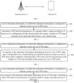
- FIG. 1 is a schematic diagram of a communication system provided by an embodiment of the disclosure.
- the communication system may include, but is not limited to, a network device and a terminal.
- the number and form of devices illustrated in FIG. 1 are only for examples and do not constitute a limitation on the embodiments of the disclosure, and two or more network devices and two or more terminals may be included in practical applications.
- the communication system shown in FIG. 1 includes a network device 11 and a terminal 12.
- LTE long term evolution
- 5G 5th generation
- NR 5G new radio
- the network device 11 in the embodiments of the disclosure is an entity on a network side for transmitting or receiving signals.
- the network device 11 may be an evolved NodeB (eNB), a transmission reception point (TRP), a next generation NodeB (gNB) in a NR system, a base station in other future mobile communication systems, or an access node in a wireless fidelity (WiFi) system.
- eNB evolved NodeB
- TRP transmission reception point
- gNB next generation NodeB
- WiFi wireless fidelity
- the specific technology and specific device form adopted by the network device are not limited in the embodiments of the disclosure.
- the network device provided by the embodiments of the disclosure may be composed of a central unit (CU) and a distributed unit (DU).
- the CU may also be called control unit.
- CU-DU structure allows to divide a protocol layer of the network device, such as a base station, such that some functions of the protocol layer are placed in the CU for centralized control, and some or all of the remaining protocol layer functions are distributed in the DU, and the DU is centrally controlled by the CU.
- the terminal 12 in the embodiments of the disclosure is an entity on a user side for receiving or transmitting signals, such as a cellular phone.
- the terminal may also be referred to as terminal, user equipment (UE), mobile station (MS), mobile terminal (MT), and the like.
- the terminal can be a car with communication functions, a smart car, a mobile phone, a wearable device, a Pad, a computer with wireless transceiver functions, a virtual reality (VR) terminal, an augmented reality (AR) terminal, a wireless terminal in industrial control, a wireless terminal in self-driving, a wireless terminal in remote medical surgery, a wireless terminal in smart grid, a wireless terminal in transportation safety, a wireless terminal in smart city, a wireless terminal in smart home, etc.
- the specific technology and specific device form adopted by the terminal are not limited in the embodiments of the disclosure.
- a method for determining a TCI state according to a configuration for a channel and/or a signal is proposed. This ensures that the terminal and network device maintain a consistency in TCI state adoption, and ensures the transmission reliability.
- the method for determining a TCI state provided in any embodiment can be executed alone, or can be executed in combination with possible implementations in other embodiments, or can be executed in combination with any technical solution in the related art.
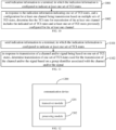
- FIG. 2 is a flowchart of a method for determining a TCI state provided by an embodiment of the disclosure. The method is performed by a terminal. As illustrated in FIG. 2 , the method may include, but is not limited to, the following steps.
- indication information is received, in which the indication information is configured to indicate at least one set of TCI states.
- One set of TCI states refers to one TCI state or a pair of TCI states.
- one set of TCI states may be a joint TCI state (or joint downlink (DL) TCI state), or a separate DL TCI state, or a separate uplink (UL) TCI state; or a separate DL TCI state and a separate UL TCI state, which is not limited in the disclosure.
- the indication information may be a medium access control (MAC) control element (CE), which may be used to activate at least one set of TCI states associated with a code point.
- MAC medium access control
- CE control element
- the indication information may also be a MAC CE and DCI. That is, the MAC CE is used to directly activate at least one set of TCI states respectively associated with multiple code points, and the DCI indicates one of the code points, and this one code point is associated with at least one set of TCI states.
- a TCI state for transmission of a channel and/or a signal is determined according to at least one of a configuration for the channel and/or the signal, a number of TCI states indicated in the indication information, or a channel type.
- the channel or channel type includes at least one of: a PDCCH, a PDSCH, a dynamic-grant PUSCH, a configured-grant type 2 PUSCH, repetition of a configured-grant type 2 PUSCH, repetition of a configured-grant type 1 PUSCH, a configured-grant type 1 PUSCH, or a PUCCH.
- the dynamic-grant PUSCH may also be called dynamic grant PUSCH.
- the configured-grant type 2 PUSCH can also be called type 2 configured grant PUSCH or configured grant type 2 PUSCH.
- the configured-grant type 1 PUSCH can also be called type 1 configured grant PUSCH or configured grant type 1 PUSCH.
- the signal includes at least one of: a channel state information reference signal (CSI RS) or a sounding reference signal (SRS).
- CSI RS channel state information reference signal
- SRS sounding reference signal
- the above-mentioned signal may be any of the following signal types: periodic, semi-persistent, and aperiodic.
- one set of TCI states of the at least one set of TCI states indicated by the indication information includes a joint TCI state (or called a joint DL TCI state), i.e., the joint TCI state may be used for both UL and DL channels/signals.
- one set of TCI states of the at least one set of TCI states indicated by the indication information includes a separate UL TCI state and/or a DL TCI state.
- the terminal may determine a TCI state used for transmission of a channel according to a channel type, or may determine a TCI state for transmission of a channel and/or a signal according to a configuration for the channel and/or the signal. Alternatively, the terminal may determine a TCI state for transmission of a channel and/or a signal according to a number of sets of TCIs specifically indicated in the indication information. Alternatively, the terminal may determine a TCI state for transmission of a channel and/or a signal according to a configuration for the channel and/or the signal and a number of sets of TCIs specifically indicated in the indication information, which is not limited in the disclosure.
- the configuration for the channel and/or the signal may be used to describe whether the channel or the signal is transmitted based on one set of TCI states or multiple sets of TCI states.
- the configuration may be determined according to a number of transmission reception points (TRPs) configured for the channel and/or the signal. For example, if the CSI RS and the SRS are each configured with a single TRP (S-TRP), it can be determined that their configurations are transmission based on one set of TCI states. If the PDCCH is configured with multiple TRPs (M-TRP), it can be determined that the configuration for the PDCCH is transmission based on multiple sets of TCI states.
- TRPs transmission reception points
- the above signals may all be transmitted based on an S-TRP, i.e., the configuration for each signal is transmission based on one set of TCI states.
- channel transmission may be transmission based on at least two sets of TCI states and/or repetition.
- the number of TCI states indicated by the indication information is one set of TCI states or at least two sets of TCI states indicated in the indication information.
- the channel type indicates that the channel is one type or some types of the above mentioned types of channels.
- the configuration for the at least one channel is transmission based on one set of TCI states, or the configuration for the at least one channel is transmission based on multiple sets of TCI states.
- the combination of configurations for each channel may include: S-TRP PDCCH and M-TRP PDSCH; S-TRP PDSCH and M-TRP PDCCH; S-TRP PDCCH and M-TRP PUSCH; S-TRP PUSCH and M-TRP PDCCH; S-TRP PUSCH and M-TRP PDSCH; S-TRP PDSCH and M-TRP PUSCH; S-TRP PDCCH, M-TRP PDSCH and M-TRP PUSCH; S-TRP PDCCH, M-TRP PDSCH and M-TRP PUCCH; S-TRP PDCCH, S-TRP PUCCH, M-TRP PDSCH and M-TRP PUSCH; S-TRP PDCCH, M-TRP PUCCH, M-TRP PDSCH and M-TRP PUSCH, and the like.
- the M-TRP PDCCH refers to a PDCCH including two search space (SS) sets that have a linked relation, PDCCH candidates with the same number in the two SS sets are used to transmit one PDCCH, and the SS sets are associated with respective control resource sets (CORESETs).
- the M-TRP PDCCH may also include a single frequency network (SFN) method, which means that one CORESET is configured with two TCI states, and any PDCCH candidate of the CORESET is associated with the two TCI states.
- SFN single frequency network
- the M-TRP PDSCH refers to a PDSCH configured with a repetition scheme, a repetition number, or two code division multiplexing (CDM) groups.
- the repetition scheme includes at least one of: a frequency division multiplexing (FDM) scheme A, a FDM scheme B, or a time division multiplexing (TDM) scheme A.
- the M-TRP PUSCH refers to a PUSCH that is associated with at least one of: two SRS resource indicators, two layer fields, two PUSCH precoder fields, or two SRS resource sets.
- the M-TRP PUCCH refers to a PUCCH that is associated with at least one of: two pieces of spatial-relation-info, two TCI states (including separate UL TCI state or joint TCI state), or two power control parameter sets.
- the terminal after receiving at least one set of TCI states indicated by the network device, the terminal can determine a TCI state for transmission of a channel and/or a signal according to at least one of a configuration for the channel and/or the signal, a number of TCI states indicated in the indication information, or a channel type, such that the TCI state determined by the terminal for transmission of the channel and/or the signal is consistent with the TCI state determined by the network device, thereby ensuring the transmission reliability and improving the transmission quality.
- FIG. 3 is a flowchart of a method for determining a TCI state provided by an embodiment of the disclosure. The method is performed by a terminal. As illustrated in FIG. 3 , the method may include, but is not limited to, the following steps.
- indication information is received, in which the indication information is configured to indicate at least one set of TCI states.
- step 301 The specific implementation in the step 301 can be described in detail with reference to any embodiment of the disclosure and will not be repeated herein.
- a TCI state used for transmission of the channel is a TCI state included in the at least two sets of TCI states.
- the channel transmitted based on at least two sets of TCI states may be any one of: a PDCCH, a PDSCH, a dynamic-grant PUSCH, a configured-grant type 2 PUSCH, repetition of a configured-grant type 2 PUSCH, repetition of a configured-grant type 1 PUSCH, a configured-grant type 1 PUSCH, and a PUCCH.
- the configured-grant type 2 PUSCH, the repetition of a configured-grant type 2 PUSCH and the repetition of a configured-grant type 1 PUSCH require to be indicated by the DCI.
- the configured-grant type 1 PUSCH does not require to be indicated by the DCI.
- the terminal may determine that the TCI state used for transmission of the channel is a TCI state included in the at least two sets of TCI states, such that the TCI state determined by the terminal for transmission of the channel and/or the signal is consistent with the TCI state determined by the network device, thereby ensuring the transmission reliability and improving the transmission quality.
- FIG. 4 is a flowchart of a method for determining a TCI state provided by an embodiment of the disclosure. The method is performed by a terminal. As illustrated in FIG. 4 , the method may include, but is not limited to, the following steps.
- indication information is received, in which the indication information is configured to indicate at least one set of TCI states.
- step 401 For the specific implementation in the step 401 reference can be made to the detailed description of any embodiment of the disclosure, which will not be repeated herein again.
- step 402 in response to the indication information indicating one set of TCI states, it is determined that a TCI state for transmission of a channel and/or a signal is the indicated set of TCI states.
- the terminal may then determine that it can only perform transmission based on the newly indicated set of TCI states.
- the channel may be caused to temporarily fall back to transmission based on one set of TCI states, i.e., S-TRP transmission.
- the terminal may determine that the TCI state used for transmission of a part of the channels is the indicated set of TCI states.
- these channels are configured for transmission based on multiple sets of TCI states.
- the terminal can determine that the TCI state used for transmission of these channels is the indicated set of TCI states.
- the terminal may determine that the TCI state used for transmission of this PDCCH is the set of TCI states indicated by the indication information. That is, transmission of the PDCCH temporarily falls back to transmission based on one set of TCI states, i.e., S-TRP transmission.
- the second CORESET described above is configured with SFN methods, including SFN method 1 and SFN method 2. That is, the PDCCH can be transmitted on the PDCCH candidate associated with this CORESET using the same time-frequency domain resource and the same port, but in different TCI states.
- the terminal can determine that the TCI state used for transmission of the first PDCCH is the set of TCI states indicated by the indication information. That is, the terminal only needs to receive the PDCCH based on the set of TCI states indicated by the indication information on the PDCCH candidate associated with the set of TCI states indicated by the indication information, and there is no need to monitor the other PDCCH candidate that is not indicated with a TCI state.
- the terminal when the terminal receives a set of TCI states indicated by the network device, it can determine that transmission of some of the above channels is based on the indicated set of TCI states. That is, if the above configuration for some of the channels is transmission based on multiple sets of TCI states, it is necessary to temporarily switch to transmission based on one set of TCI states, that is, to fall back to S-TRP.
- the terminal can also determine the TCI states used for transmitting the rest of the channels based on the configurations for these channels. For example, if a channel or signal is configured to be based on one set of TCI states, it can be determined that the channel or signal is transmitted based on the set of TCI states. For a channel configured to be based on multiple sets of TCI states, the TCI states for transmission can be configured in other ways, which is not limited herein.
- the terminal after receiving one set of TCI states indicated by the network device, the terminal can determine the TCI state for transmission of the channel or signal to be the indicated set of TCI states, such that the TCI state determined by the terminal for transmission of the channel and/or the signal is consistent with the TCI state determined by the network device, which ensures the transmission reliability and improves the quality of transmission.
- FIG. 5 is a flowchart of a method for determining a TCI state provided by an embodiment of the disclosure. The method is performed by a terminal. As illustrated in FIG. 5 , the method may include, but is not limited to, the following steps.
- indication information is received, in which the indication information is configured to indicate at least one set of TCI states.
- step 501 reference can be made to the detailed description of any embodiment of the disclosure, which will not be repeated herein again.
- the TCI state for transmission of the at least one channel includes the indicated set of TCI states and at least one set of TCI states previously configured for the at least one channel.
- the terminal may determine that the TCI state used for transmission of the channel includes the indicated set of TCI states and at least one set of TCI states previously configured for the channel.
- the at least one set of TCI states previously configured for the channel refers to at least one set of TCI states indicated by the latest indication information before the indication information.
- the PDCCH is configured to be based on two sets of TCI states, and the indication information indicates only one set of TCI states, it is determined that the PDCCH can be transmitted based on the newly indicated set of TCI states and at least one set of TCI states previously configured for the PDCCH.
- the indication information at time t1 indicates a first set of TCI states and a second set of TCI states
- the indication information at time t2 indicates a third set of TCI states. If the terminal determines that the third set of TCI states is an update for the first set of TCI states, the terminal can use the third set of TCI states and the second set of TCI states as the TCI states for transmission of the PDCCH.
- the time t1 is the time closest to the time t2 at which the indication information is received.
- the terminal may determine that the third set of TCI states is an update for the first set of TCI states according to the indication information or other configuration information, or according to default rules, which is not limited here.
- the terminal may determine the TCI state for transmission of the PDCCH to be the current indicated set of TCI states, or the current indicated set of TCI states and at least one set of TCI states previously configured for the PDCCH.
- the indication information at time t1 indicates a first set of TCI states and a second set of TCI states
- the indication information at time t2 indicates a third set of TCI states.
- the terminal may only use the third set of TCI states as the TCI state for transmission of the PDCCH, or the terminal determines that the third set of TCI states is an update for the first set of TCI state, and then the terminal uses the third set of TCI states and the second set of TCI states as the TCI states for transmission of the PDCCH.
- the time t1 is the time closest to the time t2 at which the indication information is received.
- the terminal may determine that the third set of TCI states is an update for the first set of TCI states according to the indication information or other configuration information, or according to default rules, which is not limited here.
- the second CORESET described above is configured with SFN methods, including SFN method 1 and SFN method 2. That is, the PDCCH can be transmitted on the PDCCH candidate associated with this CORESET using the same time-frequency domain resource and the same port, but in different TCI states.
- the terminal when the terminal receives the indication information that indicates a set of TCI states, it can determine that the TCI state used for transmission of the PDCCH is the current indicated set of TCI states, or the current indicated set of TCI states and at least one set of TCI states previously configured for the PDCCH.
- the indication information at time t1 indicates a first set of TCI states and a second set of TCI states
- the terminal determines that the first set of TCI states is associated with a first PDCCH candidate and the second set of TCI states is associated with a second PDCCH candidate.
- the indication information at time t2 indicates a third set of TCI states. If the terminal determines that the third set of TCI states is associated with the first PDCCH candidate, the terminal may use only the third set of TCI states as the TCI state for transmission of the PDCCH, that is, the terminal only uses the third set of TCI states to receive the PDCCH on the first PDCCH candidate.
- the terminal determines that the third set of TCI states is an update for the first set of TCI states, the terminal may use the third set of TCI states and the second set of TCI states as TCI states for transmission of the PDCCH. That is, the terminal uses the third set of TCI states to receive the PDCCH on the first PDCCH candidate and uses the second set of TCI states to receive the PDCCH on the second PDCCH candidate.
- the time t1 is the time closest to the time t2 at which the indication information is received.
- the terminal determines that the first set of TCI states is associated with the first PDCCH candidate and the second set of TCI states is associated with the second PDCCH candidate, and determines that the third set of TCI states is an update for the first set of TCI states, according to the indication information or other configuration information, or according to default rules, which is not limited here.
- the terminal may only determine that the TCI state used for transmission of a specific channel includes the indicated set of TCI states and at least one set of TCI states previously configured for the specific channel.
- the specific channel may be a configured-grant type 1 PUSCH or a PUCCH.
- the terminal after receiving the set of TCI states indicated by the network device, when multiple sets of TCI states are configured for at least one channel, the terminal can determine that the TCI state used for transmission of at least one channel includes the indicated set of TCI states and at least one set of TCI states previously configured for the at least one channel, such that the TCI state determined by the terminal for transmission of the channel and/or the signal is consistent with the TCI state determined by the network device, thereby ensuring the reliability of transmission and improving the transmission quality.
- FIG. 6 is a flowchart of a method for determining a TCI state provided by an embodiment of the disclosure. The method is performed by a terminal. As illustrated in FIG. 6 , the method may include, but is not limited to, the following steps.
- indication information is received, in which the indication information is configured to indicate at least one set of TCI states.
- step 601 reference can be made to the detailed description of any embodiment of the disclosure, which will not be repeated herein again.
- one set of TCI states used for the transmission of the channel and/or the signal is determined based on a group identifier associated with the channel and/or the signal.
- the channel or channel type includes at least one of: a PDCCH, a PDSCH, a configured-grant type 1 PUSCH, a configured-grant type 2 PUSCH, a dynamic-grant PUSCH, or a PUCCH.
- the signal includes at least one of: a CSI-RS or an SRS.
- the terminal may determine a group identifier of a channel or signal in any of the following ways: receiving configuration information configured to indicate a group identifier associated with a channel and/or a signal; or, in response to the channel being a first PUCCH, and a resource location of the first PUCCH being determined based on a parameter of a first CORESET, determining a group identifier associated with the first CORESET as a group identifier associated with the first PUCCH; or, in response to the channel being a second PUCCH with a number greater than a threshold, and a resource location of the second PUCCH being determined based on a total number of CCEs of a second CORESET and a CCE start position of a PDCCH candidate, determining a group identifier associated with the second CORESET as a group identifier associated with the second PUCCH; or, in response to the channel being a PDCCH, determining a group identifier of a CORESET or a CORE
- the indication information may include a group identifier (ID, which can also be called identity document) or an index associated with each set of TCI states.
- ID which can also be called identity document
- the terminal may determine the set of TCI states associated with the group identifier associated with the channel or the signal in the indication information as the TCI state for transmission of the channel and/or the signal.
- FIG. 7 is a flowchart of a method for determining a TCI state provided by an embodiment of the disclosure.
- the method is performed by a network device.
- the method may include, but is not limited to, the following steps.
- indication information is sent to a terminal, in which the indication information is configured to indicate at least one set of TCI states.
- One set of TCI states refers to one TCI state or a pair of TCI states.
- one set of TCI states may be a joint TCI state (or joint DL TCI state), or a separate DL TCI state, or a separate UL TCI state, or a separate DL TCI state and a separate UL TCI state, which is not limited in the disclosure.
- the indication information may be a MAC CE, which may be used to activate at least one set of TCI states associated with a code point.
- the indication information may also be a MAC CE and DCI. That is, the MAC CE may be used to directly activate at least one set of TCI states associated with multiple code points, and the DCI indicates one of the code points, and this one code point is associated with at least one set of TCI states.
- a TCI state for transmission of a channel and/or a signal is determined according to at least one of a configuration for the channel and/or the signal of the terminal, a number of TCI states indicated in the indication information, or a channel type.
- the channel or channel type includes at least one of: a PDCCH, a PDSCH, a dynamic-grant PUSCH, a configured-grant type 2 PUSCH, repetition of a configured-grant type 2 PUSCH, repetition of a configured-grant type 1 PUSCH, a configured-grant type 1 PUSCH, or a PUCCH.
- the dynamic-grant PUSCH may also be called dynamic grant PUSCH.
- the configured-grant type 2 PUSCH may also be called type 2 configured grant PUSCH or configured grant type 2 PUSCH.
- the configured-grant type 1 PUSCH may also be called type 1 configured grant PUSCH or configured grant type 1 PUSCH.
- the signal includes at least one of: a CSI RS or an SRS.
- the above-mentioned signal may be any of the following signal types: periodic, semi-persistent, and aperiodic.
- one set of TCI states of the at least one set of TCI states indicated by the indication information includes a joint TCI state, i.e., the joint TCI state may be used for both UL and DL channels/signals.
- one set of TCI states of the at least one set of TCI states indicated by the indication information includes a separate UL TCI state and/or a DL TCI state.
- the terminal may determine a TCI state used for transmission of a channel according to a channel type; or may determine a TCI state for transmission of a channel and/or a signal according to a configuration for the channel and/or the signal; or may determine a TCI state for transmission of a channel and/or a signal according to a number of sets of TCIs specifically indicated in the indication information; or may determine a TCI state for transmission of a channel and/or a signal according to a configuration for the channel and/or the signal and a number of sets of TCIs specifically indicated in the indication information, which is not limited in the disclosure.
- the configuration for the channel and/or the signal for the terminal may be used to describe whether the channel or the signal is transmitted based on one set of TCI states or multiple sets of TCI states.
- the configuration may be determined according to a number of TRPs configured for the channel and/or the signal. For example, if the CSI RS and the SRS are each configured with an S-TRP, it can be determined that their configurations are transmission based on one set of TCI states. If the PDCCH is configured with M-TRP, it can be determined that the configuration for the PDCCH is transmission based on multiple sets of TCI states.
- the above signals may all be transmitted based on an S-TRP, i.e., the configuration for each signal is transmission based on one set of TCI states.
- channel transmission may be transmission based on at least two sets of TCI states and/or repetition.
- the number of TCI states indicated by the indication information is one set of TCI states or at least two sets of TCI states indicated in the indication information.
- the channel type indicates that the channel is one type or some types of the above mentioned types of channels.
- the configuration for the at least one channel is transmission based on one set of TCI states, or the configuration for the at least one channel is transmission based on multiple sets of TCI states.
- the combination of configurations for each channel may include: S-TRP PDCCH and M-TRP PDSCH; S-TRP PDSCH and M-TRP PDCCH; S-TRP PDCCH and M-TRP PUSCH; S-TRP PUSCH and M-TRP PDCCH; S-TRP PUSCH and M-TRP PDSCH; S-TRP PDSCH and M-TRP PUSCH; S-TRP PDCCH, M-TRP PDSCH and M-TRP PUSCH; S-TRP PDCCH, M-TRP PDSCH and M-TRP PUCCH; S-TRP PDCCH, S-TRP PUCCH, M-TRP PDSCH and M-TRP PUSCH; S-TRP PDCCH, M-TRP PUCCH, M-TRP PDSCH and M-TRP PUSCH, and the like.
- the M-TRP PDCCH refers to a PDCCH including two SS sets that have a linked relation, PDCCH candidates with the same number in the two SS sets are used to transmit one PDCCH, and the SS sets are associated with respective CORESETs.
- the M-TRP PDCCH may also include an SFN method, which means that one CORESET is configured with two TCI states, and any PDCCH candidate of the CORESET is associated with the two TCI states.
- the M-TRP PDSCH refers to a PDSCH configured with a repetition scheme, a repetition number, or two CDM groups.
- the repetition scheme includes at least one of: a FDM scheme A, a FDM scheme B, or a TDM scheme A.
- the M-TRP PUSCH refers to a PUSCH that is associated with at least one of: two SRS resource indicators, two layer fields, two PUSCH precoder fields, or two SRS resource sets.
- the M-TRP PUCCH refers to a PUCCH that is associated with at least one of: two pieces of spatial-relation-info, two TCI states (including separate UL TCI state or joint TCI state), or two power control parameter sets.
- the terminal after receiving at least one set of TCI states indicated by the network device, the terminal can determine a TCI state for transmission of a channel and/or a signal according to at least one of a configuration for the channel and/or the signal, a number of TCI states indicated in the indication information, or a channel type, such that the TCI state determined by the terminal for transmission of the channel and/or the signal is consistent with the TCI state determined by the network device, thereby ensuring the transmission reliability and improving the transmission quality.
- FIG. 8 is a flowchart of a method for determining a TCI state provided by an embodiment of the disclosure.
- the method is performed by a network device.
- the method may include, but is not limited to, the following steps.
- indication information is sent to a terminal, in which the indication information is configured to indicate at least one set of TCI states.
- step 801 reference can be made to the detailed description of any embodiment of the disclosure, which will not be repeated herein again.
- a TCI state used for transmission of the channel is a TCI state included in the at least two sets of TCI states.
- the channel transmitted based on at least two sets of TCI states may be any one of: a PDCCH, a PDSCH, a dynamic-grant PUSCH, a configured-grant type 2 PUSCH, repetition of a configured-grant type 2 PUSCH, repetition of a configured-grant type 1 PUSCH, a configured-grant type 1 PUSCH, and a PUCCH.
- the configured-grant type 2 PUSCH, the repetition of a configured-grant type 2 PUSCH and the repetition of a configured-grant type 1 PUSCH require to be indicated by the DCI.
- the configured-grant type 1 PUSCH does not require to be indicated by the DCI.
- the terminal may determine that the TCI state used for transmission of the channel is a TCI state included in the at least two sets of TCI states, such that the TCI state determined by the terminal for transmission of the channel and/or the signal is consistent with the TCI state determined by the network device, thereby ensuring the transmission reliability and improving the transmission quality.
- FIG. 9 is a flowchart of a method for determining a TCI state provided by an embodiment of the disclosure.
- the method is performed by a network device.
- the method may include, but is not limited to, the following steps.
- indication information is sent to a terminal, in which the indication information is configured to indicate at least one set of TCI states.
- step 901 reference can be made to the detailed description of any embodiment of the disclosure, which will not be repeated herein again.
- step 902 in response to the indication information indicating one set of TCI states, it is determined that a TCI state for transmission of a channel and/or signal is the indicated set of TCI states.
- the terminal may then determine that it can only perform transmission based on the newly indicated set of TCI states.
- the channel may be caused to temporarily fall back to transmission based on one set of TCI states, i.e., S-TRP transmission.
- the terminal may determine that the TCI state used for transmission of a part of the channels is the indicated set of TCI states.
- these channels are configured for transmission based on multiple sets of TCI states.
- the terminal may determine that the TCI state used for transmission of these channels is the indicated set of TCI states.
- the second CORESET is configured with at least two sets of TCI states, if the current indication information indicates only one set of TCI states, the terminal may determine that the TCI state used for transmission of this PDCCH is the set of TCI states indicated by the indication information. That is, transmission of the PDCCH temporarily falls back to transmission based on one set of TCI states, i.e., S-TRP transmission.
- the second CORESET described above is configured with SFN methods, including SFN method 1 and SFN method 2. That is, the PDCCH can be transmitted on the PDCCH candidate associated with this CORESET using the same time-frequency domain resource and the same port, but in different TCI states.
- the terminal can determine that the TCI state used for transmission of the first PDCCH is the set of TCI states indicated by the indication information. That is, the terminal only needs to receive the PDCCH based on the set of TCI states indicated by the indication information on the PDCCH candidate associated with the set of TCI states indicated by the indication information. There is no need to monitor the other PDCCH candidate that is not indicated with a TCI state.
- the terminal when the terminal receives a set of TCI states indicated by the network device, it can determine that transmission for some of the above channels is based on the indicated set of TCI states. That is, if the above configuration for some of the channels is transmission based on multiple sets of TCI states, it is necessary to temporarily switch to transmission based on one set of TCI states, that is, to fall back to S-TRP.
- the terminal can also determine the TCI states used for transmitting the rest of the channels based on the configurations for these channels. For example, if a channel or signal is configured to be based on one set of TCI states, it can be determined that the channel or signal is transmitted based on the set of TCI states. For a channel configured to be based on multiple sets of TCI states, the TCI states for transmission can be configured in other ways, which is not limited herein.
- the terminal after receiving one set of TCI states indicated by the network device, the terminal can determine the TCI state for transmission of the channel or signal to be the indicated set of TCI states, such that the TCI state determined by the terminal for transmission of the channel and/or the signal is consistent with the TCI state determined by the network device, which ensures the transmission reliability and improves the quality of transmission.
- FIG. 10 is a flowchart of a method for determining a TCI state provided by an embodiment of the disclosure.
- the method is performed by a network device.
- the method may include, but is not limited to, the following steps.
- indication information is sent to a terminal, in which the indication information is configured to indicate at least one set of TCI states.
- step 1001 reference can be made to the detailed description of any embodiment of the disclosure, which will not be repeated herein again.
- the TCI state for transmission of the at least one channel includes the indicated set of TCI states and at least one set of TCI states previously configured for the at least one channel.
- the network device may determine that the TCI state used for transmission of the one or more channels includes the indicated set of TCI states and at least one set of TCI states previously configured for the one or more channels.
- the at least one set of TCI states previously configured for the channel refers to at least one set of TCI states indicated by the latest indication information before the indication information.
- the PDCCH is configured to be based on two sets of TCI states, and the indication information indicates only one set of TCI states, it is determined that the PDCCH can be transmitted based on the newly indicated set of TCI states and at least one set of TCI states previously configured for the PDCCH.
- the indication information at time t1 indicates a first set of TCI states and a second set of TCI states
- the indication information at time t2 indicates a third set of TCI states. If the network device determines that the third set of TCI states is an update for the first set of TCI states, the network device can use the third set of TCI states and the second set of TCI states as the TCI states for transmission of the PDCCH.
- the time t1 is the time closest to the time t2 at which the indication information is sent.
- the network device may determine that the third set of TCI states is an update for the first set of TCI states according to the indication information or other configuration information, or according to default rules, which is not limited here.
- the network device may determine the TCI state for transmission of the PDCCH to be the current indicated set of TCI states, or the current indicated set of TCI states and at least one set of TCI states previously configured for the PDCCH.
- the indication information at time t1 indicates a first set of TCI states and a second set of TCI states
- the indication information at time t2 indicates a third set of TCI states
- the network device may only use the third set of TCI states as the TCI state for transmission of the PDCCH, or the network device determines that the third set of TCI states is an update for the first set of TCI state, and then the network device uses the third set of TCI states and the second set of TCI states as the TCI states for transmission of the PDCCH.
- the time t1 is the time closest to the time t2 at which the indication information is sent.
- the network device may determine that the third set of TCI states is an update for the first set of TCI states according to the indication information or other configuration information, or according to default rules, which is not limited here.
- the second CORESET described above is configured with SFN methods, including SFN method 1 and SFN method 2. That is, the PDCCH can be transmitted on the PDCCH candidate associated with this CORESET using the same time-frequency domain resource and the same port, but in different TCI states.
- the first PDCCH includes two PDCCH candidates, two SS sets associated with the two PDCCH candidates have a linked relation, and the SS sets are associated with respective CORESETs
- the network device when the network device indicates the indication information that indicates a set of TCI states, it can determine that the TCI state used for transmission of the PDCCH is the current indicated set of TCI states, or the current indicated set of TCI states and at least one set of TCI states previously configured for the PDCCH.
- the indication information at time t1 indicates a first set of TCI states and a second set of TCI states
- the network device determines that the first set of TCI states is associated with a first PDCCH candidate and the second set of TCI states is associated with a second PDCCH candidate.
- the indication information at time t2 indicates a third set of TCI states.
- the network device may use only the third set of TCI states as the TCI state for transmission of the PDCCH, that is, the network device only uses the third set of TCI states to send the PDCCH on the first PDCCH candidate; or the network device determines that the third set of TCI states is an update for the first set of TCI states, the network device can use the third set of TCI states and the second set of TCI states as TCI states for transmission of the PDCCH. That is, the network device uses the third set of TCI states to send the PDCCH on the first PDCCH candidate and uses the second set of TCI states to send the PDCCH on the second PDCCH candidate.
- the time t1 is the time closest to the time t2 at which the indication information is sent.
- the network device determines that the first set of TCI states is associated with the first PDCCH candidate and the second set of TCI states is associated with the second PDCCH candidate, and determines that the third set of TCI states is an update for the first set of TCI states, according to the indication information or other configuration information, or according to default rules, which is not limited here.
- the network device may only determine that the TCI state used for transmission of a specific channel includes the indicated set of TCI states and at least one set of TCI states previously configured for the specific channel.
- the specific channel may be a configured-grant type 1 PUSCH or a PUCCH.
- the network device can determine that the TCI state used for transmission of at least one channel includes the indicated set of TCI states and at least one set of TCI states previously configured for the at least one channel, such that the TCI state determined by the terminal for transmission of the channel and/or the signal is consistent with the TCI state determined by the network device, thereby ensuring the reliability of transmission and improving the transmission quality.
- FIG. 11 is a flowchart of a method for determining a TCI state provided by an embodiment of the disclosure.
- the method is performed by a network device.
- the method may include, but is not limited to, the following steps.
- indication information is sent to a terminal, in which the indication information is configured to indicate at least one set of TCI states.
- transmission of one set of TCI states used for the transmission of the channel and/or the signal is determined based on a group identifier associated with the channel and/or the signal.
- the channel or channel type includes at least one of: a PDCCH, a PDSCH, a configured-grant type 1 PUSCH, a configured-grant type 2 PUSCH, a dynamic-grant PUSCH, or a PUCCH.
- the signal includes at least one of: a CSI-RS and an SRS.
- the terminal may determine a group identifier of a channel or signal in any of the following ways: receiving configuration information configured to indicate a group identifier associated with a channel and/or a signal; or, in response to the channel being a first PUCCH, and a resource location of the first PUCCH being determined based on a parameter of a first CORESET, determining a group identifier associated with the first CORESET as a group identifier associated with the first PUCCH; or, in response to the channel being a second PUCCH with a number greater than a threshold, and a resource location of the second PUCCH being determined based on a total number of CCEs of a second CORESET and a CCE start position of a PDCCH candidate, determining a group identifier associated with the second CORESET as a group identifier associated with the second PUCCH; or, in response to the channel being a PDCCH, determining a group identifier of a CORESET or a CORE
- the indication information may include a group identifier (ID, which can also be called identity document) or an index associated with each set of TCI states.
- ID which can also be called identity document
- the terminal may determine the set of TCI states associated with the group identifier associated with the channel or the signal in the indication information as the TCI state for transmission of the channel and/or the signal.
- the group identifier includes at least one of: a CORESET pool index, a CORESET group identifier, a PUCCH group identifier, a PUSCH group identifier, or a PDSCH group identifier.
- the first indication information may include a CORESET pool index, a CORESET group ID, a PUCCH group ID, a PUSCH group ID or a PDSCH group ID associated with each set of TCI states.
- a TCI state whose associated group ID in the indication information is the same as a group ID of the channel or signal is determined as the set of TCI states for transmission of the channel or signal, such that the TCI state determined by the terminal for transmission of the channel and/or the signal is consistent with the TCI state determined by the network device, thereby ensuring the transmission reliability and improving the quality of the transmission.
- FIG. 12 is a schematic diagram of a communication device 1200 provided by an embodiment of the disclosure.
- the communication device 1200 shown in FIG. 12 may include a transceiver module 1201.
- the transceiver module 1201 may include a transmitting module and/or a receiving module.
- the transmitting module is used for realizing a transmitting function
- the receiving module is used for realizing a receiving function.
- the transceiver module 1201 may realize the transmitting function and/or the receiving function.
- the communication device 1200 may be a terminal, a device in the terminal, or a device capable of being used together with the terminal.
- one set of TCI states in the at least one set of TCI states includes a joint TCI state; or one set of TCI states in the at least one set of TCI states includes a separate UL TCI state and/or DL TCI state.
- the channel includes at least one of: a PDCCH, a PDSCH, a dynamic-grant PUSCH, a configured-grant type 2 PUSCH, repetition of a configured-grant type 2 PUSCH, repetition of a configured-grant type 1 PUSCH, a configured-grant type 1 PUSCH, or a PUCCH.
- the signal includes at least one of: a CSI RS or an SRS.
- the configuration for the channel is transmission based on at least two sets of TCI states and/or repetition.
- the processing module 1202 is configured to: in response to the indication information indicating at least two sets of TCI states, determine that the TCI state for transmission of the channel is a TCI state included in the at least two sets of TCI states.
- the processing module 1202 is configured to: in response to the indication information indicating one set of TCI states, determine that the TCI state for transmission of the channel and/or the signal is the indicated set of TCI states; or in response to the indication information indicating one set of TCI states, and a configuration for at least one channel being transmission based on multiple sets of TCI states, determine that the TCI state for transmission of the at least one channel is the indicated set of TCI states and at least one set of TCI states previously configured for the at least one channel.
- the processing module 1202 is configured to: in response to the channel being the PDSCH, the dynamic-grant PUSCH, the configured-grant type 2 PUSCH, the repetition of the configured-grant type 2 PUSCH, or the repetition of the configured-grant type 1 PUSCH, determine that the TCI state for transmission of the channel is the indicated set of TCI states.
- the processing module 1202 is configured to: in response to the at least one channel being the configured-grant type 1 PUSCH or the PUCCH, determine that the TCI state for transmission of the PUSCH or PUCCH includes the indicated set of TCI states and at least one set of TCI states previously configured for the PUSCH or the PUCCH.
- the processing module 1202 is configured to: in response to the transmission of the channel and/or the signal being based on one set of TCI states, determine transmission of one set of TCI states used for the transmission of the channel and/or the signal based on a group identifier associated with the channel and/or the signal;
- the transceiver module 1201 is configured to: receive configuration information, in which the configuration information is configured to indicate the group identifier associated with the channel and/or the signal; or
- the indication information includes a group identifier associated with each set of TCI states.
- the group identifier includes at least one of: a CORESET pool index, a CORESET group identifier, a PUCCH group identifier, a PUSCH group identifier, or a PDSCH group identifier.
- the channel includes:
- the indication information includes a MAC CE, or DCI and a MAC CE.
- the terminal after receiving at least one set of TCI states indicated by the network device, the terminal can determine a TCI state for transmission of a channel and/or a signal according to at least one of a configuration for the channel and/or the signal, a number of TCI states indicated in the indication information or a channel type, such that the TCI state determined by the terminal for transmission of the channel and/or the signal is consistent with the TCI state determined by the network device, thereby ensuring the transmission reliability and improving the transmission quality.
- the communication device 1200 may be a network device, a device in the network device, or a device capable of being used together with the network device.
- one set of TCI states in the at least one set of TCI states includes a joint TCI state; or one set of TCI states in the at least one set of TCI states includes a separate UL TCI state and/or DL TCI state.
- the channel includes at least one of: a PDCCH, a PDSCH, a dynamic-grant PUSCH, a configured-grant type 2 PUSCH, repetition of a configured-grant type 2 PUSCH, repetition of a configured-grant type 1 PUSCH, a configured-grant type 1 PUSCH, or a PUCCH.
- the signal includes at least one of: a CSI RS or an SRS.
- the configuration for the channel is transmission based on at least two sets of TCI states and/or repetition.
- the processing module 1202 is configured to: in response to the indication information indicating at least two sets of TCI states, determine that the TCI state for transmission of the channel is a TCI state included in the at least two sets of TCI states.
- the processing module 1202 is configured to: in response to the indication information indicating one set of TCI states, determine that the TCI state for transmission of the channel and/or the signal is the indicated set of TCI states; or in response to the indication information indicating one set of TCI states, and a configuration for at least one channel being transmission based on multiple sets of TCI states, determine that the TCI state for transmission of the at least one channel is the indicated set of TCI states and at least one set of TCI states previously configured for the at least one channel.
- the processing module 1202 is configured to: in response to the channel being a PDSCH, a dynamic-grant PUSCH, a configured-grant type 2 PUSCH, repetition of a configured-grant type 2 PUSCH, or repetition of a configured-grant type 1 PUSCH, determine that the TCI state for transmission of the channel is the indicated set of TCI states.
- the processing module 1202 is configured to: in response to the at least one channel being the configured-grant type 1 PUSCH or the PUCCH, determine that the TCI state for transmission of the PUSCH or PUCCH includes the indicated set of TCI states and at least one set of TCI states previously configured for the PUSCH or PUCCH.
- the processing module 1202 is configured to: in response to the transmission of the channel and/or the signal being based on one set of TCI states, determine transmission of one set of TCI states used for the transmission of the channel and/or the signal based on a group identifier associated with the channel and/or the signal;
- the transceiver module 1201 is configured to: receive configuration information, in which the configuration information is configured to indicate the group identifier associated with the channel and/or the signal; or
- the indication information includes a group identifier associated with each set of TCI states.
- the group identifier includes at least one of: a CORESET pool index, a CORESET group identifier, a PUCCH group identifier, a PUSCH group identifier, or a PDSCH group identifier.
- the channel includes:
- the indication information includes a MAC CE, or DCI and a MAC CE.
- the network device can determine a TCI state for transmission of a channel and/or a signal according to at least one of a configuration for the channel and/or the signal, a number of TCI states indicated in the indication information or a channel type, such that the TCI state determined by the terminal for transmission of the channel and/or the signal is consistent with the TCI state determined by the network device, thereby ensuring the transmission reliability and improving the transmission quality.
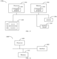
- FIG. 13 is a schematic diagram of a communication device 1300 provided by an embodiment of the disclosure.
- the communication device 1300 may be a network device, a communication assisting device, a terminal, or a chip, a chip system or a processor that supports the network device to realize the above-described methods, or a chip, a chip system or a processor that supports the communication assisting device to realize the above-described methods, or a chip, a chip system or a processor that supports the terminal to realize the above-described methods.
- the device may be used to realize the methods described in the above method embodiments with reference to the description of the above-described method embodiments.
- the communication device 1300 may include one or more processors 1301.
- the processor 1301 may be a general purpose processor or a dedicated processor, such as, a baseband processor or a central processor.
- the baseband processor is used for processing communication protocols and communication data.
- the central processor is used for controlling the communication device (e.g., base station, baseband chip, terminal, terminal chip, DU, or CU), executing computer programs, and processing data of the computer programs.
- the communication device 1300 may include one or more memories 1302 on which a computer program 1304 may be stored.
- the processor 1301 executes the computer program 1304 to cause the communication device 1300 to perform the methods described in the above method embodiments.
- the memory 1302 may also store data.
- the communication device 1300 and the memory 1302 may be provided separately or may be integrated together.
- the communication device 1300 may also include a transceiver 1305 and an antenna 1306.
- the transceiver 1305 may be referred to as transceiver unit, transceiver machine, or transceiver circuit, for realizing the transceiver function.
- the transceiver 1305 may include a receiver and a transmitter.
- the receiver may be referred to as receiver machine or receiving circuit, for realizing the receiving function.
- the transmitter may be referred to as transmitter machine or transmitting circuit, for realizing the transmitting function.
- the communication device 1300 may also include one or more interface circuits 1307.
- the interface circuits 1307 are used to receive code instructions and transmit them to the processor 1301.
- the processor 1301 runs the code instructions to cause the communication device 1300 to perform the methods described in the method embodiments.
- the transceiver 1305 may perform step 201 in FIG. 2 .
- the processor 1301 is used to perform step 202 in FIG. 2 and step 302 in FIG. 3 .
- the transceiver 1305 is used to perform step 701 in FIG. 7 , step 801 in FIG. 8 , and step 901 in FIG. 9 .
- the processor 1301 is used to perform step 702 in FIG. 7 and step 802 in FIG. 8 .
- the processor 1301 may include a transceiver for implementing the receiving and transmitting functions.
- the transceiver may be, for example, a transceiver circuit, an interface, or an interface circuit.
- the transceiver circuit, interface, or interface circuit for implementing the receiving and transmitting functions may be separated or may be integrated together.
- the transceiver circuit, interface, or interface circuit described above may be used for code/data reading and writing, or may be used for signal transmission or delivery.
- the processor 1301 may store a computer program 1303.
- the computer program 1303 runs on the processor 1301 and causes the communication device 1300 to perform the methods described in the method embodiments above.
- the computer program 1303 may be solidified in the processor 1301, in which case the processor 1301 may be implemented by hardware.
- the communication device 1300 may include circuits.
- the circuits may implement the sending, receiving or communicating function in the preceding method embodiments.
- the processor and transceiver described in this disclosure may be implemented on integrated circuits (ICs), analog ICs, radio frequency integrated circuits (RFICs), mixed signal ICs, application specific integrated circuits (ASICs), printed circuit boards (PCBs), and electronic devices.
- ICs integrated circuits
- RFICs radio frequency integrated circuits
- ASICs application specific integrated circuits
- PCBs printed circuit boards
- the processor and the transceiver may also be produced using various IC process technologies, such as complementary metal oxide semiconductor (CMOS), nMetal-oxide-semiconductor (NMOS), positive channel metal oxide semiconductor (PMOS), bipolar junction transistor (BJT), bipolar CMOS (BiCMOS), silicon-germanium (SiGe), gallium arsenide (GaAs) and so on.
- CMOS complementary metal oxide semiconductor
- NMOS nMetal-oxide-semiconductor
- PMOS positive channel metal oxide semiconductor
- BJT bipolar junction transistor
- BiCMOS bipolar CMOS
- SiGe silicon-germanium
- GaAs gallium arsenide
- the communication device described in the above embodiments may be a network device, a terminal, or a communication assisting device, but the scope of the communication device described in the disclosure is not limited thereto, and the structure of the communication device may not be limited by FIG. 13 .
- the communication device may be a stand-alone device or may be part of a larger device.
- the communication device may be:
- the communication device is a chip or a chip system may be referred to the schematic diagram of a chip shown in FIG. 14 .
- the chip includes a processor 1401 and an interface 1403. There may be one or more processors 1401, and there may be multiple interfaces 1403.
- the interface 1403 is configured to executed step 201 in FIG. 2 .
- the interface 1403 is configured to execute step 701 in FIG. 7 , step 801 in FIG. 8 , and step 901 in FIG. 9 .
- the chip further includes a memory 1402 used for storing necessary computer programs and data.
- the disclosure also provides a readable storage medium having instructions stored thereon. When the instructions are executed by a computer, the function of any of the method embodiments described above is implemented.
- the disclosure also provides a computer program product.
- the computer program product is executed by a computer, the function of any of the method embodiments described above is implemented.
- the above embodiments may be implemented in whole or in part by software, hardware, firmware, or any combination thereof.
- software When implemented using software, it may be implemented, in whole or in part, in the form of a computer program product.
- the computer program product includes one or more computer programs. When loading and executing the computer program on the computer, all or part of processes or functions described in the embodiments of the disclosure are implemented.
- the computer may be a general-purpose computer, a dedicated computer, a computer network, or other programmable devices.
- the computer program may be stored in a computer-readable storage medium or transmitted from one computer-readable storage medium to another computer-readable storage medium.
- the computer program may be transmitted from one web site, computer, server, or data center to another web site, computer, server, or data center, in a wired manner (e.g., by using coaxial cables, fiber optics, or digital subscriber lines (DSLs) or wirelessly (e.g., by using infrared wave, wireless wave, or microwave).
- the computer-readable storage medium may be any usable medium to which the computer has access or a data storage device integrated by one or more usable mediums such as a server and a data center.
- the usable medium may be a magnetic medium (e.g., floppy disk, hard disk, and tape), an optical medium (e.g., a high-density digital video disc (DVD)), or a semiconductor medium (e.g., a solid state disk (SSD)).
- a magnetic medium e.g., floppy disk, hard disk, and tape
- an optical medium e.g., a high-density digital video disc (DVD)
- DVD high-density digital video disc
- SSD solid state disk
- the term “at least one” in the disclosure may also be described as one or more, and the term “multiple” may be two, three, four, or more, which is not limited in the disclosure.
- “first”, “second”, and “third”, and “A”, “B”, “C” and “D” are used to distinguish different technical features of the type, the technical features described using the “first”, “second”, and “third”, and “A”, “B”, “C” and “D” do not indicate any order of precedence or magnitude.
- the correspondences shown in the tables in this disclosure may be configured or may be predefined.
- the values of information in the tables are merely examples and may be configured to other values, which are not limited by the disclosure.
- the correspondences illustrated in certain rows in the tables in this disclosure may not be configured.
- the above tables may be adjusted appropriately, such as splitting, combining, and the like.
- the names of the parameters shown in the titles of the above tables may be other names that may be understood by the communication device, and the values or representations of the parameters may be other values or representations that may be understood by the communication device.
- Each of the above tables may also be implemented with other data structures, such as, arrays, queues, containers, stacks, linear tables, pointers, chained lists, trees, graphs, structures, classes, heaps, and Hash tables.
- predefine in this disclosure may be understood as define, define in advance, store, pre-store, pre-negotiate, pre-configure, solidify, or pre-fire.
Landscapes
- Engineering & Computer Science (AREA)
- Signal Processing (AREA)
- Computer Networks & Wireless Communication (AREA)
- Quality & Reliability (AREA)
- Mobile Radio Communication Systems (AREA)
- Small-Scale Networks (AREA)
Applications Claiming Priority (1)
| Application Number | Priority Date | Filing Date | Title |
|---|---|---|---|
| PCT/CN2022/089678 WO2023206179A1 (fr) | 2022-04-27 | 2022-04-27 | Procédé et dispositif de détermination d'état d'indication de configuration |
Publications (2)
| Publication Number | Publication Date |
|---|---|
| EP4518201A1 true EP4518201A1 (fr) | 2025-03-05 |
| EP4518201A4 EP4518201A4 (fr) | 2025-06-25 |
Family
ID=83023198
Family Applications (1)
| Application Number | Title | Priority Date | Filing Date |
|---|---|---|---|
| EP22939032.3A Pending EP4518201A4 (fr) | 2022-04-27 | 2022-04-27 | Procédé et dispositif de détermination d'état d'indication de configuration |
Country Status (6)
| Country | Link |
|---|---|
| US (1) | US20250274242A1 (fr) |
| EP (1) | EP4518201A4 (fr) |
| JP (1) | JP2025515311A (fr) |
| KR (1) | KR20250004333A (fr) |
| CN (1) | CN115004589B (fr) |
| WO (1) | WO2023206179A1 (fr) |
Cited By (1)
| Publication number | Priority date | Publication date | Assignee | Title |
|---|---|---|---|---|
| EP4668964A4 (fr) * | 2023-02-15 | 2026-04-29 | Beijing Xiaomi Mobile Software Co Ltd | Procédé et appareil de détermination d'état d'indication de configuration de transmission, support de stockage |
Families Citing this family (13)
| Publication number | Priority date | Publication date | Assignee | Title |
|---|---|---|---|---|
| WO2023151656A1 (fr) * | 2022-02-10 | 2023-08-17 | 维沃移动通信有限公司 | Procédé et appareil de détermination d'état de tci de liaison descendante, terminal et dispositif côté réseau |
| WO2024050774A1 (fr) * | 2022-09-08 | 2024-03-14 | 北京小米移动软件有限公司 | Procédé/appareil/dispositif de détermination d'informations et support d'enregistrement |
| EP4586564A4 (fr) * | 2022-09-08 | 2025-11-12 | Beijing Xiaomi Mobile Software Co Ltd | Procédé/appareil/dispositif de détermination d'informations, et support de stockage |
| CN115997455A (zh) * | 2022-10-14 | 2023-04-21 | 北京小米移动软件有限公司 | 一种信息确定方法/装置/设备及存储介质 |
| WO2024082312A1 (fr) * | 2022-10-21 | 2024-04-25 | 北京小米移动软件有限公司 | Procédé et appareil de détermination d'état d'indicateur de configuration de transmission et support de stockage |
| EP4607835A4 (fr) * | 2022-10-21 | 2025-12-10 | Beijing Xiaomi Mobile Software Co Ltd | Procédé et appareil de détermination d'état d'indicateur de configuration de transmission, et support de stockage |
| EP4608029A4 (fr) * | 2022-10-21 | 2025-12-17 | Beijing Xiaomi Mobile Software Co Ltd | Procédé, appareil et dispositif de détermination d'état d'indication de configuration de transmission et support de stockage |
| WO2024168557A1 (fr) * | 2023-02-14 | 2024-08-22 | 北京小米移动软件有限公司 | Procédé et dispositif de détermination d'état d'indication de configuration de transmission, procédé et dispositif de configuration d'état d'indication de configuration de transmission, et support de stockage |
| WO2024168636A1 (fr) * | 2023-02-15 | 2024-08-22 | 北京小米移动软件有限公司 | Procédé, appareil et dispositif de configuration d'état d'indication de configuration de transmission, et support de stockage |
| WO2024168744A1 (fr) * | 2023-02-16 | 2024-08-22 | 富士通株式会社 | Appareil et procédé de réception et de transmission de données |
| WO2024234158A1 (fr) * | 2023-05-12 | 2024-11-21 | 北京小米移动软件有限公司 | Procédé et appareil de transmission d'informations |
| CN120343741A (zh) * | 2024-01-18 | 2025-07-18 | 中国移动通信有限公司研究院 | Tci指示配置方法、设备及存储介质 |
| WO2026031240A1 (fr) * | 2024-08-09 | 2026-02-12 | 北京小米移动软件有限公司 | Procédé de détermination d'état, et terminal, dispositif de réseau, système, et support de stockage |
Family Cites Families (11)
| Publication number | Priority date | Publication date | Assignee | Title |
|---|---|---|---|---|
| CN109802787B (zh) * | 2017-11-17 | 2021-01-08 | 维沃移动通信有限公司 | 传输配置指示tci的传输方法、网络侧设备和终端设备 |
| CN111586846B (zh) * | 2019-02-15 | 2024-02-20 | 成都华为技术有限公司 | 传输配置编号状态指示的方法和通信装置 |
| JP7445357B2 (ja) * | 2019-08-15 | 2024-03-07 | 株式会社Nttドコモ | 端末、無線通信方法及びシステム |
| CN112787786B (zh) * | 2019-11-08 | 2022-03-25 | 维沃移动通信有限公司 | 信道信息的确定方法、网络设备及终端设备 |
| US11751174B2 (en) * | 2020-01-16 | 2023-09-05 | Qualcomm Incorporated | Signaling for configuring downlink transmissions |
| CN115226117B (zh) * | 2020-02-07 | 2024-07-02 | 维沃移动通信有限公司 | 波束指示方法、装置、设备及介质 |
| CN113260058B (zh) * | 2020-02-13 | 2023-03-24 | 维沃移动通信有限公司 | 下行控制信息传输方法、终端设备和网络设备 |
| US12089195B2 (en) * | 2020-04-06 | 2024-09-10 | Samsung Electronics Co., Ltd. | Method and apparatus for uplink reference signal-based beam management |
| EP4192071A4 (fr) * | 2020-07-31 | 2024-05-01 | Ntt Docomo, Inc. | Terminal, procédé de communication sans fil, et station de base |
| CN114337947B (zh) * | 2020-09-29 | 2024-11-15 | 维沃移动通信有限公司 | 确定传输模式的方法、装置和通信设备 |
| WO2022077478A1 (fr) * | 2020-10-16 | 2022-04-21 | 华为技术有限公司 | Procédé de communication basé sur un faisceau, et appareil associé |
-
2022
- 2022-04-27 WO PCT/CN2022/089678 patent/WO2023206179A1/fr not_active Ceased
- 2022-04-27 US US18/859,773 patent/US20250274242A1/en active Pending
- 2022-04-27 CN CN202280001351.7A patent/CN115004589B/zh active Active
- 2022-04-27 KR KR1020247039142A patent/KR20250004333A/ko active Pending
- 2022-04-27 EP EP22939032.3A patent/EP4518201A4/fr active Pending
- 2022-04-27 JP JP2024562925A patent/JP2025515311A/ja active Pending
Cited By (1)
| Publication number | Priority date | Publication date | Assignee | Title |
|---|---|---|---|---|
| EP4668964A4 (fr) * | 2023-02-15 | 2026-04-29 | Beijing Xiaomi Mobile Software Co Ltd | Procédé et appareil de détermination d'état d'indication de configuration de transmission, support de stockage |
Also Published As
| Publication number | Publication date |
|---|---|
| US20250274242A1 (en) | 2025-08-28 |
| EP4518201A4 (fr) | 2025-06-25 |
| KR20250004333A (ko) | 2025-01-07 |
| WO2023206179A1 (fr) | 2023-11-02 |
| JP2025515311A (ja) | 2025-05-14 |
| CN115004589B (zh) | 2024-07-02 |
| CN115004589A (zh) | 2022-09-02 |
Similar Documents
| Publication | Publication Date | Title |
|---|---|---|
| EP4518201A1 (fr) | Procédé et dispositif de détermination d'état d'indication de configuration | |
| EP4518202A1 (fr) | Procédé de détermination d'état d'indication de configuration de transmission et appareil | |
| JP7686877B2 (ja) | 伝送設定指示(tci)状態設定方法及びその装置 | |
| US20250379710A1 (en) | Method for determining application time of tci state, and terminal | |
| US20250274915A1 (en) | Methods and apparatuses for data transmission | |
| US20250358083A1 (en) | Indication methods for transmission configuration indication state, and apparatuses | |
| US20240292429A1 (en) | Method and device for determining application time of beam | |
| EP4712625A1 (fr) | Procédé de détermination de ressource sans autorisation de liaison montante, procédé de configuration de ressource sans autorisation de liaison montante et appareil | |
| EP4586564A1 (fr) | Procédé/appareil/dispositif de détermination d'informations, et support de stockage | |
| EP4546687A1 (fr) | Procédé et appareil de détermination d'informations de localisation d'une ressource de commande | |
| US20240163017A1 (en) | Methods for processing data reception, related communication apparatus and storage medium | |
| US20240187280A1 (en) | Triggering method for joint channel estimation and user equipment | |
| US20260031948A1 (en) | Method and apparatus for multi-panel enhanced transmission configuration | |
| US20260012933A1 (en) | Methods and apparatuses for determining control resource set (coreset) #0 | |
| US20250038896A1 (en) | Methods for determining and indicating slot offset for hybrid automatic repeat request, and related devices | |
| US20240284417A1 (en) | Time domain resource assignment method and apparatus | |
| WO2023184438A1 (fr) | Procédés et appareils d'annulation d'interférences par répartition dans le temps | |
| RU2847786C2 (ru) | Способ определения состояния индикации конфигурации передачи и устройство | |
| CN114026907A (zh) | 一种上行波束的测量方法及其装置 | |
| US20250351002A1 (en) | Method and apparatus for configuring cell state | |
| EP4637063A1 (fr) | Procédé et appareil de transmission de requête automatique de répétition hybride (harq) | |
| US20250386339A1 (en) | Indication method and apparatus | |
| US20250373315A1 (en) | Information determination method, apparatus and device, and storage medium | |
| EP4383654A1 (fr) | Procédé et appareil de programmation semi-permanente pour service de diffusion sélective/non sélective (mbs) | |
| EP4447535A1 (fr) | Procédé et appareil de configuration d'intervalle de mesure |
Legal Events
| Date | Code | Title | Description |
|---|---|---|---|
| STAA | Information on the status of an ep patent application or granted ep patent |
Free format text: STATUS: THE INTERNATIONAL PUBLICATION HAS BEEN MADE |
|
| PUAI | Public reference made under article 153(3) epc to a published international application that has entered the european phase |
Free format text: ORIGINAL CODE: 0009012 |
|
| STAA | Information on the status of an ep patent application or granted ep patent |
Free format text: STATUS: REQUEST FOR EXAMINATION WAS MADE |
|
| 17P | Request for examination filed |
Effective date: 20241121 |
|
| AK | Designated contracting states |
Kind code of ref document: A1 Designated state(s): AL AT BE BG CH CY CZ DE DK EE ES FI FR GB GR HR HU IE IS IT LI LT LU LV MC MK MT NL NO PL PT RO RS SE SI SK SM TR |
|
| REG | Reference to a national code |
Ref country code: DE Ref legal event code: R079 Free format text: PREVIOUS MAIN CLASS: H04L0001000000 Ipc: H04L0005000000 |
|
| A4 | Supplementary search report drawn up and despatched |
Effective date: 20250527 |
|
| RIC1 | Information provided on ipc code assigned before grant |
Ipc: H04L 5/00 20060101AFI20250521BHEP |
|
| DAV | Request for validation of the european patent (deleted) | ||
| DAX | Request for extension of the european patent (deleted) |