EP4518217A1 - Procédé et appareil de configuration pour cellule d?économie d?énergie de réseau - Google Patents
Procédé et appareil de configuration pour cellule d?économie d?énergie de réseau Download PDFInfo
- Publication number
- EP4518217A1 EP4518217A1 EP22939154.5A EP22939154A EP4518217A1 EP 4518217 A1 EP4518217 A1 EP 4518217A1 EP 22939154 A EP22939154 A EP 22939154A EP 4518217 A1 EP4518217 A1 EP 4518217A1
- Authority
- EP
- European Patent Office
- Prior art keywords
- cell
- terminal equipment
- network device
- information
- saving
- Prior art date
- Legal status (The legal status is an assumption and is not a legal conclusion. Google has not performed a legal analysis and makes no representation as to the accuracy of the status listed.)
- Pending
Links
Images


Classifications
-
- H—ELECTRICITY
- H04—ELECTRIC COMMUNICATION TECHNIQUE
- H04W—WIRELESS COMMUNICATION NETWORKS
- H04W52/00—Power management, e.g. Transmission Power Control [TPC] or power classes
- H04W52/02—Power saving arrangements
-
- H—ELECTRICITY
- H04—ELECTRIC COMMUNICATION TECHNIQUE
- H04L—TRANSMISSION OF DIGITAL INFORMATION, e.g. TELEGRAPHIC COMMUNICATION
- H04L5/00—Arrangements affording multiple use of the transmission path
-
- H—ELECTRICITY
- H04—ELECTRIC COMMUNICATION TECHNIQUE
- H04L—TRANSMISSION OF DIGITAL INFORMATION, e.g. TELEGRAPHIC COMMUNICATION
- H04L5/00—Arrangements affording multiple use of the transmission path
- H04L5/0001—Arrangements for dividing the transmission path
-
- H—ELECTRICITY
- H04—ELECTRIC COMMUNICATION TECHNIQUE
- H04W—WIRELESS COMMUNICATION NETWORKS
- H04W52/00—Power management, e.g. Transmission Power Control [TPC] or power classes
- H04W52/02—Power saving arrangements
- H04W52/0203—Power saving arrangements in the radio access network or backbone network of wireless communication networks
- H04W52/0206—Power saving arrangements in the radio access network or backbone network of wireless communication networks in access points, e.g. base stations
-
- H—ELECTRICITY
- H04—ELECTRIC COMMUNICATION TECHNIQUE
- H04W—WIRELESS COMMUNICATION NETWORKS
- H04W52/00—Power management, e.g. Transmission Power Control [TPC] or power classes
- H04W52/02—Power saving arrangements
- H04W52/0209—Power saving arrangements in terminal devices
- H04W52/0212—Power saving arrangements in terminal devices managed by the network, e.g. network or access point is leader and terminal is follower
- H04W52/0216—Power saving arrangements in terminal devices managed by the network, e.g. network or access point is leader and terminal is follower using a pre-established activity schedule, e.g. traffic indication frame
-
- Y—GENERAL TAGGING OF NEW TECHNOLOGICAL DEVELOPMENTS; GENERAL TAGGING OF CROSS-SECTIONAL TECHNOLOGIES SPANNING OVER SEVERAL SECTIONS OF THE IPC; TECHNICAL SUBJECTS COVERED BY FORMER USPC CROSS-REFERENCE ART COLLECTIONS [XRACs] AND DIGESTS
- Y02—TECHNOLOGIES OR APPLICATIONS FOR MITIGATION OR ADAPTATION AGAINST CLIMATE CHANGE
- Y02D—CLIMATE CHANGE MITIGATION TECHNOLOGIES IN INFORMATION AND COMMUNICATION TECHNOLOGIES [ICT], I.E. INFORMATION AND COMMUNICATION TECHNOLOGIES AIMING AT THE REDUCTION OF THEIR OWN ENERGY USE
- Y02D30/00—Reducing energy consumption in communication networks
- Y02D30/70—Reducing energy consumption in communication networks in wireless communication networks
Definitions
- Embodiments of the present disclosure relate to the technical field of communications.
- NR New Radio
- a NR (New Radio) base station needs to operate on a large bandwidth (such as 100MHz), it needs to use a large number of ports (64T/64R) and a shorter TTI (transmission time interval) (such as 1ms)
- energy consumption of the NR base station in terms of functions such as baseband processing, digital front end, etc. is significantly higher than that of an LTE (Long Term Evolution) base station.
- an FR2 (frequency range 2) operating frequency (>6GHz) of NR is higher, and the higher a frequency point, the greater a path loss of a signal, so a design principle of NR is to use a narrower beam to transmit the signal farther.
- each radio frequency channel is provided with a power amplifier (PA)
- PA power amplifier
- the energy consumption of the PA will account for about 80% of the energy consumption of the whole base station, and the energy consumption of the base station will increase with the increase of the number of PAs.
- a current FR1 (frequency range 1) frequency band AAU (Active Antenna Unit) generally uses 192 antenna units and supports 64 channels, which is much larger than at most 8 channels for LTE.
- NR base station According to data statistics from operators, average energy consumption of a NR base station is more than three times that of an LTE base station, and nearly 50% of the cost for deploying a 5G (5th generation) network by operators is electricity fee overhead. More importantly, the energy consumption of the NR base station is still high even when there is no traffic, because even when there is no traffic, the base station still needs to transmit common signals, such as an SSB (synchronization signal block), an SIB1 (a system information block type 1) and SI (system information), so the energy use efficiency of the NR base station is greatly reduced. NR network energy saving is a problem demanding prompt solution.
- SSB synchronization signal block
- SIB1 system information block type 1
- SI system information
- a NR cell stopping transmitting system information is supported.
- the NR cell broadcasts whether to transmit SI in SIB1. If a UE (user equipment) needs to receive the SI (for example, when the UE determines that the saved SI needs to be updated), it may request the base station to resume transmitting SI. The NR base station resumes transmitting the SI when receiving a relevant UE request.
- 3GPP Rel-15/Rel-16 (Third Generation Partnership Project Release 15/ Release 16)
- network energy saving for NR has been studied, and a proposed solution is to dynamically start and stop reception and/or transmission of signals of a NR cell according to information such as traffic volumes of the NR cell and its adjacent cell and UE measurement reports.
- the reception and transmission of signals of the NR cell is stopped, the cell enters into an energy-saving state.
- a purpose in which the NR cell turns off a device for transmitting and receiving a signal to save energies in a case where a traffic volume is lower may be achieved.
- Whether or not the NR enters into the energy-saving state may be decided by the NR cell itself (a distributed network energy-saving scheme) or by an OAM (a centralized network energy-saving scheme). For example, when the traffic volume of the NR cell is lower than a certain threshold, it is determined to enter into the energy-saving state.
- FIG. 1 is a schematic diagram of a distributed network energy-saving scheme.
- the base station switches the UE to an adjacent cell, and informs an adj acent NR base station or LTE base station that the NR cell has entered into the energy-saving state, and the adjacent NR/LTE base station will be responsible to the coverage areas and traffic volume of the NR cell.
- the adj acent NR/LTE base station will determine whether to request the NR cell that has entered into the energy-saving state to resume normal operation according to information such as its own traffic volume, UE measurement report.
- the request to the NR cell that has entered into the energy-saving state to resume normal operation is triggered.
- the NR cell resumes normal operation i.e. restarts reception and/or transmission of signals, some UEs that were previously switched to the adjacent NR/LTE cell will switch back to the NR cell.
- an apparatus for configuring a network energy-saving cell configured in a network device, the apparatus includes: a transmitting unit, configured to transmit first information to a terminal equipment, the first information being used to configure a second cell to the terminal equipment so that the network device serves for the terminal equipment by using the second cell; wherein energies needed by the network device in operating the second cell are lower than energies needed by the network device in operating a first cell.
- an apparatus for configuring a network energy-saving cell configured in a terminal equipment, the apparatus includes: a receiving unit, configured to receive first information transmitted by a network device, the first information being used to configure a second cell to the terminal equipment so that the network device serves for the terminal equipment by using the second cell; wherein energies needed by the network device in operating the second cell are lower than energies needed by the network device in operating a first cell.
- an energy-saving cell still may be used to serve for a terminal equipment.
- a terminal equipment in an IDLE/INACTIVE state is capable of normally camping on an energy-saving cell; or, a terminal equipment in a connected state may continue to perform uplink and downlink data transmissions via an energy-saving cell.
- a terminal equipment in the energy-saving cell is migrated to an adjacent cell, resulting in traffic interruption of the terminal equipment and increasing a load level of the adjacent cell.
- first and second are used to distinguish different elements in terms of appellation, but do not represent a spatial arrangement or time sequence, etc. of these elements, and these elements should not be limited by these terms.
- the term “and/or” includes any and all combinations of one or more of the associated listed terms.
- the terms “include”, “comprise” and “have”, etc. refer to the presence of stated features, elements, members or components, but do not preclude the presence or addition of one or more other features, elements, members or components.
- a communication network or “a wireless communication network” may refer to a network that meets any of the following communication standards, such as Long Term Evolution (LTE), LTE-Advanced (LTE-A), Wideband Code Division Multiple Access (WCDMA), HighSpeed Packet Access (HSPA) and so on.
- LTE Long Term Evolution
- LTE-A LTE-Advanced
- WCDMA Wideband Code Division Multiple Access
- HSPA HighSpeed Packet Access
- communication between devices in a communication system can be carried out according to a communication protocol at any stage, for example may include but be not limited to the following communication protocols: 1G (generation), 2G, 2.5G, 2.75G, 3G, 4G, 4.5G, 5G, New Radio (NR) and so on, and/or other communication protocols that are currently known or will be developed in the future.
- 1G generation
- 2G 2.5G, 2.75G
- 3G 3G
- 4G 4.5G
- 5G New Radio
- a network device refers to, for example, a device that accesses a terminal equipment in a communication system to a communication network and provides services to the terminal equipment.
- the network device may include but be not limited to the following devices: a Base Station (BS), an Access Point (AP), a Transmission Reception Point (TRP), a broadcast transmitter, a Mobile Management Entity (MME), a gateway, a server, a Radio Network Controller (RNC), a Base Station Controller (BSC) and so on.
- BS Base Station
- AP Access Point
- TRP Transmission Reception Point
- MME Mobile Management Entity
- RNC Radio Network Controller
- BSC Base Station Controller
- the base station may include but be not limited to: node B (NodeB or NB), evolution node B (eNodeB or eNB) and a 5G base station (gNB), etc., and may further includes Remote Radio Head (RRH), Remote Radio Unit (RRU), a relay or a low power node (such as femeto, pico, etc.), Integrated Access and Backhaul (IAB) node or IAB-DU or IAB-donor.
- RRH Remote Radio Head
- RRU Remote Radio Unit
- IAB Integrated Access and Backhaul
- base station may include some or all functions of a base station, each base station may provide communication coverage to a specific geographic region.
- a cell may refer to a base station and/or its coverage area, which depends on the context in which this term is used. Where there is no confusion, the terms "cell” and " base station " are interchangeable.
- the term "User Equipment (UE)” or “Terminal Equipment (TE) or Terminal Device” refers to, for example, a device that accesses a communication network and receives network services through a network device.
- the terminal equipment can be fixed or mobile, and can also be referred to as Mobile Station (MS), a terminal, Subscriber Station (SS), Access Terminal (AT), IAB-MT, a station and so on.
- MS Mobile Station
- SS Subscriber Station
- AT Access Terminal
- IAB-MT IAB-MT
- the terminal equipment may include but be not limited to the following devices: a Cellular Phone, a Personal Digital Assistant (PDA), a wireless modem, a wireless communication device, a handheld device, a machine-type communication device, a laptop computer, a cordless phone, a smart phone, a smart watch, a digital camera and so on.
- PDA Personal Digital Assistant
- the terminal equipment may also be a machine or apparatus for monitoring or measurement, for example may include but be not limited to: a Machine Type Communication (MTC) terminal, a vehicle-mounted communication terminal, a Device to Device (D2D) terminal, a Machine to Machine (M2M) terminal and so on.
- MTC Machine Type Communication
- D2D Device to Device
- M2M Machine to Machine
- a network side or “a network device side” refers to a side of a network, may be a base station, and may include one or more network devices as described above.
- a user side or “a terminal side” or “a terminal equipment side” refers to a side of a user or terminal, may be a UE, and may include one or more terminal equipments as described above. If it is not specifically mentioned herein, "a device” may refer to a network device, or may refer to a terminal equipment.
- Embodiments of the present disclosure provide a method for configuring a network energy-saving cell.
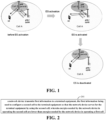
- FIG. 2 is a schematic diagram of a method for configuring a network energy-saving cell in the embodiments of the present disclosure.
- the method includes: 201, a network device transmits first information to a terminal equipment, the first information being used to configure a second cell to the terminal equipment so that the network device serves for the terminal equipment by using the second cell; wherein energies needed by the network device in operating the second cell are lower than energies needed by the network device in operating a first cell.
- FIG. 2 only schematically describes the embodiments of the present disclosure, but the present disclosure is not limited to this. For example, other some operations can be increased or operations therein may be reduced. Persons skilled in the art may make appropriate modifications according to the above contents, not limited to the records in the above FIG. 2 .
- an energy-saving cell still may be used to serve for a terminal equipment.
- a terminal equipment in an IDLE/INACTIVE state is capable of normally camping on an energy-saving cell; or, a terminal equipment in a connected state may continue to perform uplink and downlink data transmissions via an energy-saving cell.
- a terminal equipment in the energy-saving cell is migrated to an adjacent cell, resulting in traffic interruption of the terminal equipment and increasing a load level of the adjacent cell.
- energies needed by the network device in operating the second cell are lower than energies needed by the network device in operating the first cell, i.e., electrical energies consumed by the network device when transmitting at a peak rate by using the second cell are lower than electrical energies consumed by the network device when transmitting at the peak rate by using the first cell, or, electrical energies consumed by the network device when transmitting a unit data volume by using the second cell are lower than electrical energies consumed by the network device when transmitting the unit data volume by using the first cell.
- the network device configures the second cell (i.e., an energy-saving cell) for the terminal equipment which has been configured with the first cell (i.e., a non-energy-saving cell) as a serving cell and is in a connected state, or may configure the second cell (i.e., an energy-saving cell) for the terminal equipment which is newly accessed to a network and is in a connected state, so that the second cell serves for the terminal equipment which is in the connected state.
- the second cell i.e., an energy-saving cell
- the network device may further transmit system information of the second cell, so that a terminal equipment which is in an idle or inactive state camps on the second cell, so that the second cell serves for the terminal equipment which is in the idle or inactive state.
- the network device may achieve multiple energy-saving modes via hardware or software, so that the second cell saves more electrical energy consumption than the first cell.
- the network device achieves energy saving in a time domain.
- the network device makes a transmission period of a common signal of the second cell to be longer than a transmission period of a common signal of the first cell via software, so that the second cell is more energy saving than the first cell. That is, the transmission period of the common signal of the second cell is extended.
- the common signal here may be an SSB (synchronization signal block), an SS (synchronization signal), an MIB (main information block), a PBCH (physical broadcast channel), an SIB1 (system information block), SI (system information), and paging, etc.
- the present disclosure is not limited to this.
- a transmission period ssb-periodicity of an SSB of the second cell is longer than that of the first cell; for another example, transmission periods of an SIB1 and SI of the second cell are longer than those of the first cell; for a further example, a period of a PDCCH (physical downlink control channel) search space for system information of the second cell is longer than that of the first cell; for another example, a paging period defaultPagingCycle or a period of a PDCCH search space for paging of the second cell is longer than that of the first cell, etc.
- a PDCCH physical downlink control channel
- the network device stops transmission of a part of downlink time units of the second cell via hardware or software, so that the second cell is more energy saving than the first cell. That is, transmission of partial frames, subframes or slots, symbols of the second cell is stopped.
- the network device realizes that transmission of a part of downlink time units on each BWP of the second cell is stopped by means of e.g. turning off radio frequency units of the second cell in part of downlink time units.
- the network device does not transmit a part of signals of the second cell via software or transmit a simplified common signal of the second cell, so that the second cell is more energy saving than the first cell.
- the common signal here may be an SSB (synchronization signal block), an SS (synchronization signal), an MIB (main information block), a PBCH (physical broadcast channel), an SIB1 (system information block), SI (system information), and paging, etc.
- the present disclosure is not limited to this.
- the second cell does not transmit a full SSB, only transmits a reference signal (SS) in the SSB, stops transmission of an MIB or a PBCH, and does not transmit an SIB1 and SI, that is, the second cell only transmits a simplified SSB and does not transmit system broadcast information.
- the second cell only transmits an SSB, and does not transmit an SIB1 and SI, that is, the second cell only transmits a non-cell defined SSB (NCD-SSB).
- NCD-SSB non-cell defined SSB
- the network device makes the number of symbols of a CSI-RS (channel state information reference signal) of the second cell be less than the number of symbols of a CSI-RS of the first cell via software, so that the second cell is more energy saving than the first cell. That is, compared with the first cell, the number of symbols of the CSI-RS of the second cell is less.
- the network device may indicate the number of symbols of the CSI-RS of the second cell to the terminal equipment through a CSI-RS resource configuration field in a downlink BWP configuration of the second cell, the present disclosure is not limited to this.
- the network device achieves energy saving in a space domain.
- the network device makes the number of transmission antenna elements of the second cell to be less than the number of transmission antenna elements of the first cell via hardware, so that the second cell is more energy saving than the first cell. That is, compared with the first cell, the number of transmission antenna elements including relevant radio frequency channels, power amplifiers of the second cell is less.
- the network device turns off part of the antenna elements of the second cell, including relevant radio frequency channels, power amplifiers, so that the number of transmission antenna elements of each downlink BWP of the second cell is less than that of the first cell.
- the network device makes the number of transmission beams of the second cell to be less than the number of transmission beams of the first cell via hardware or software, so that the second cell is more energy saving than the first cell. That is, compared with the first cell, the number of transmission beams of the second cell is less.
- the network device turns off radio frequency hardware corresponding to part of the beams of the second cell, so that the number of beams of the second cell is less than that of the first cell.
- the beams of the second cell may refer to SSB beams of the second cell, for example, the number of all SSB beams of the second cell is less than that of the first cell.
- the network device may indicate actual transmission beams of the second cell to the terminal equipment via a ssb-PositionsInBurst field in a system information block (SIB1) of the second cell, the present disclosure is not limited to this.
- SIB1 system information block
- the network device makes the number of MIMO (multiple input multiple output) antenna ports of the second cell to be less than the number of MIMO antenna ports of the first cell via software, so that the second cell is more energy saving than the first cell. That is, compared with the first cell, the network device transmits signals of the second cell by using fewer MIMO antenna ports. For example, the number of MIMO antenna ports per BWP of the second cell is less than that of the first cell.
- the network device may indicate the number of MIMO antenna ports of the second cell to the terminal equipment through a downlink demodulation reference signal (DMRS) configuration field in a downlink BWP configuration of the second cell, the present disclosure is not limited to this.
- DMRS downlink demodulation reference signal
- the network device achieves energy saving in a frequency domain.
- the network device makes a service bandwidth of the second cell to be different from a service bandwidth of the first cell via hardware or software, so that the second cell is more energy saving than the first cell. That is, the service bandwidth of the second cell is different from that of the first cell. For example, in a case where the service bandwidth is more energy saving when larger, the service bandwidth of the second cell is greater than that of the first cell; in a case where the service bandwidth is more energy saving when smaller, the service bandwidth of the second cell is smaller than that of the first cell.
- the network device may indicate a bandwidth of the second cell to the terminal equipment through a bandwidth configuration field in a BWP configuration of the second cell.
- the network device achieves energy saving in a power domain.
- the network device makes transmission power of the second cell to be lower than that of the first cell via software, so that the second cell is more energy saving than the first cell. That is, the transmission power of the second cell is lower than that of the first cell.
- the transmission power of the second cell may refer to transmission power ssb-PBCH-BlockPower of an SSB of the second cell.
- the transmission power of all SSBs of the second cell is lower than that of the first cell.
- the present disclosure is not limited to this, it may further be that the transmission power of an SSB of an initial BWP of the second cell is lower than that of the first cell.
- the network device may indicate transmission power of the second cell to the terminal equipment through an ssb-PBCH-BlockPower field in a cell configuration or BWP configuration of the second cell.
- each of the above embodiments only exemplarily describes energy-saving modes, but the present disclosure is not limited to this, appropriate modifications may be further made based on the above each embodiment.
- each of the above embodiments may be used individually, or one or more of the above embodiments may be combined.
- an energy-saving state may be divided into different degrees, such as light energy saving, moderate energy saving and deep energy saving, etc.
- a transmission period of an SSB of the second cell is 40ms in case of light energy saving
- the transmission period of the SSB of the second cell is 80ms in case of moderate energy saving
- the transmission period of the SSB of the second cell is 160ms in case of deep energy saving.
- the number of transmission beams of an SSB of the second cell is 4 in case of light energy saving
- the number of transmission beams of the SSB of the second cell is 2 in case of moderate energy saving
- the number of transmission beams of the SSB of the second cell is 1 in case of deep energy saving.
- the network device only reduces signal transmission of an energy-saving cell in the time domain, frequency domain, space and/or power domain, so as to ensure that the network device may still use the energy-saving cell to serve for a terminal equipment.
- a terminal equipment in an IDLE/INACTIVE state is capable of normally camping on an energy-saving cell; or, a terminal equipment in a connected state may continue to perform uplink and downlink data transmissions via an energy-saving cell.
- the first cell and the second cell occupy different frequency domain resources, for example, occupied frequency domain resources do not overlap, or the occupied frequency domain resources have different center frequency points.
- the first cell and the second cell have different PCIs (physical cell identifiers) or center frequency points.
- the network device may release air interface resources corresponding to the first cell and stop operating the first cell. In this way, the terminal equipments may be seamlessly switched or migrated to an energy-saving cell. Since different hardware resources need to be equipped for the first cell and the second cell respectively, a network does not need to restart hardware when the network device operates the second cell, which may avoid service interruption of the terminal equipment(s).
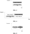
- the network device may operate the first cell and the second cell by using the same set of hardware resources, as shown in FIG. 4 .
- the network device needs to transmit signals of the first cell and of the second cell by using different time domain resources.
- Terminal equipment(s) cannot be seamlessly migrated, and after the network device starts to transmit a signal of the second cell, terminal equipment(s) connected to the first cell will be interrupted for serving. Therefore, before the network device operates the second cell, it is necessary to transmit the above first information to the terminal equipment to indicate the terminal equipment to connect to the second cell, so as to prevent service interruption.
- the first cell and the second cell occupy the same frequency domain resources, and the network device does not operate the first cell and the second cell at the same time, that is, the time domain resources occupied by the first cell and the second cell are different, as shown in FIG. 5 .
- the first cell and the second cell occupy the same frequency resources and, since they serve for the same terminal equipment, the first cell and the second cell have the same coverage area. Operating the first cell and the second cell at the same time will cause mutual interference to the terminal equipment, therefore, the first cell and the second cell need to occupy different time domain resources.
- a network may operate the first cell and the second cell by using the same set of hardware resources.
- the network may operate the first cell and the second cell by using the same set of hardware resources.
- the network device needs to transmit signals of the first cell and of the second cell by using different time domain resources.
- PCIs of the first cell and the second cell may be different.
- terminal equipment(s) cannot be seamlessly migrated, and after the network device transmits a signal of the second cell (changes a PCI), that is, after operating the second cell, terminal equipment(s) connected to the first cell will be interrupted for serving. Therefore, before the network device operates the second cell, it is necessary to transmit the above first information to the terminal equipment to indicate the terminal equipment to connect to the second cell, so as to prevent service interruption.
- the PCIs of the first cell and the second cell may further be identical.
- the second cell may be used to serve for a terminal equipment in the first cell, thereby the terminal equipment may be seamlessly migrated. If there is no need to restart hardware after the network device starts to operate the second cell, a terminal equipment connected to the first cell may not be interrupted for serving.
- the terminal equipment is not configured with a serving cell.
- the network device may configure the energy-saving cell (second cell) as a secondary cell of the terminal equipment, a primary secondary cell (a special cell SpCell in a SCG (a secondary cell group)), or a primary cell of the terminal equipment.
- the terminal equipment has been configured with a non-energy-saving cell (first cell) as a serving cell.
- the non-energy-saving cell (the first cell) is changed to an energy-saving cell (the second cell).
- the energy-saving cell (the second cell) is changed to a non-energy-saving cell (the first cell).
- the first cell is a configured or activated secondary cell of a terminal equipment. That is, the network device changes a configured or activated non-energy-saving secondary cell of the terminal equipment to be an energy-saving cell.
- the network device does not need to configure the second cell in advance, but only needs to reconfigure parameters of at least one first cell via first information to change the first cell to be the second cell. For example, after the network device enters energy saving, a network side modifies parameter configuration of at least one SCell of the terminal equipment via an RRC (radio resource control) message to configure the at least one SCell as an energy-saving SCell.
- RRC radio resource control
- the first cell may be multiple, that is, the terminal equipment has multiple configured or activated secondary cells, and the network device reconfigures parameters of at least one first cell of the terminal equipment via the above first information to change the first cell to be the second cell.
- the first information is carried via an RRC message is taken as an example, but the present disclosure is not limited to this, the first information may further be carried via other messages or signaling.
- the method in the above implementations may be used in a case where the PCIs of the first cell and the second cell are identical or different, and according to the method in the above implementations, signaling overhead is saved.
- the network device configures at least one second cell to be a secondary cell of the terminal equipment via the first information, and enables the terminal equipment to set an initial state of the second cell to be of a deactive state.
- a network side configures an energy-saving cell (the second cell) to be a secondary cell (SCell) in a primary cell group MCG or secondary cell group SCG of the terminal equipment via an RRC message, and enables the terminal equipment to set the initial state of the cell to be of a deactive state.
- FIG. 6 is another schematic diagram of a method for configuring a network energy-saving cell in the embodiments of the present disclosure.
- the network device may further transmit second information (602) to the terminal equipment; enables the terminal equipment to set the state of the second cell to be of an active state via the second information, and enables the terminal equipment to set the state of the first cell to be of a deactive state via the second information.
- the network device sets a state of an energy-saving cell (the second cell) to be of an active state via an MAC CE (media access control control element), and sets a state of a non-energy-saving cell (the first cell) to be of a deactive state via the MAC CE.
- MAC CE media access control control element
- the network device may further transmit third information (603) to the terminal equipment; enables the terminal equipment to set the state of the second cell to be of a deactive state via the third information, and enables the terminal equipment to set the state of the first cell to be of an active state via the third information.
- third information 603
- the network device sets a state of an energy-saving cell (the second cell) to be of a deactive state via an MAC CE, and enables the terminal equipment to set a state of a non-energy-saving cell (the first cell) to be of an active state.
- the first information is carried via an RRC message and the second information and the third information are carried via an MAC CE is taken as an example, but the present disclosure is not limited to this, the first information, the second information and the third information may further be carried via other messages or signaling, for example, the third information may further be carried via a PDCCH or DCI (downlink control information).
- the method in the above implementations may be used in a case where the PCIs of the first cell and the second cell are identical or different.
- the terminal equipment when the second cell is configured by the RRC message as a SCell of a terminal equipment, the terminal equipment may start to perform downlink synchronization to the second cell, and when a network side activates the second cell, the second cell may be immediately used to perform data transmission, which reduces service interruption time of the terminal equipment.
- the network device configures at least one second cell to be a secondary cell of a terminal equipment via the first information, and configures a transition timer for the terminal equipment, so that the terminal equipment starts or restarts the transition timer when a preset condition is satisfied, and deactivates the first cell and activates the second cell when the transition timer expires.
- the network device configures at least one energy-saving cell (the second cell) for the terminal equipment via an RRC message, and configures a transition timer for a non-energy-saving cell (the first cell), and if a preset condition is satisfied, the terminal equipment starts or restarts the transition timer.
- the transition timer expires, the terminal equipment deactivates the non-energy-saving cell (the first cell) and activates the energy-saving cell (the second cell).
- the transition timer is for the first cell
- the present disclosure is not limited to this, the transition timer may further be configured for other cells.
- a transition timer is configured for the second cell, and in a case where a preset condition is satisfied, the terminal equipment starts or restarts the transition timer, and when the transition timer expires, the terminal equipment activates the energy-saving cell (the second cell) and deactivates the non-energy-saving cell (the first cell).
- the network device may deactivate the first cell and activate the second cell when no data is transmitted by the terminal equipment.
- the preset condition includes at least one of the following:
- the terminal equipment when activating the first cell, the terminal equipment starts the transition timer, or when a physical downlink control channel PDCCH is received on a currently activated first cell, and/or when the PDCCH schedules an uplink grant or downlink resources on the currently activated first cell, and/or when uplink configuration grant CG data is transmitted on the currently activated first cell, and/or, when downlink configuration grant CG data is received on the currently activated first cell, the terminal equipment restarts the transition timer.
- the first information is carried via an RRC message is taken as an example, but the present disclosure is not limited to this, the first information may further be carried via other messages or signaling.
- the method in the above implementations may be used in a case where the PCIs of the first cell and the second cell are identical or different.
- the terminal equipment when the second cell is configured by the RRC message as a SCell of a terminal equipment, the terminal equipment may start to perform downlink synchronization to the second cell, and when a network side activates the second cell, the second cell may be immediately used to perform data transmission, which reduces service interruption time of the terminal equipment.
- the first cell is a special cell SpCell in a configured or activated first secondary cell group SCG of a terminal equipment. That is, the network device changes a non-energy-saving special cell SpCell in a configured or activated first secondary cell group SCG of a terminal equipment into an energy-saving cell.
- the special cell SpCell e.g., is a primary secondary cell PSCell, the present disclosure is not limited to this.
- the network device does not need to configure the second cell in advance, but only needs to reconfigure parameters of the first cell via first information to change the first cell to be the second cell. For example, after the network device enters energy saving, a network side modifies parameter configuration of a PSCell in SCG configuration of the terminal equipment via an RRC message to configure the PSCell as an energy-saving PSCell.
- the first information is carried via an RRC message is taken as an example, but the present disclosure is not limited to this, the first information may further be carried via other messages or signaling.
- the method in the above implementations may be used in a case where the PCIs of the first cell and the second cell are identical or different, and according to the method in the above implementations, signaling overhead is saved.
- the network device does not need to configure the second cell in advance, but only needs to release the first secondary cell group via the first information and set up a second secondary cell group, wherein the second cell is a special cell in the second secondary cell group.
- the configured secondary cell group is an activated secondary cell group.
- FIG. 7 is another schematic diagram of a method for configuring a network energy-saving cell in the embodiments of the present disclosure.
- the network device may further transmit fourth information (702) to the terminal equipment, and enables the terminal equipment to release the second secondary cell group and set up the first secondary cell group via the fourth information.
- fourth information 702
- the network side releases a SCG (second secondary cell group) which takes the energy-saving cell (second cell) as a special cell via an RRC message, and sets up a SCG (first secondary cell group) which takes the non-energy-saving cell (first cell) as a special cell.
- first information and the fourth information are carried via an RRC message is taken as an example, but the present disclosure is not limited to this, the first information and the fourth information may further be carried via other messages or signaling.
- the first information contains configuration for changing the first cell to be the second cell and a condition for applying the configuration, so that the terminal equipment changes the first cell to be the second cell in a case where the condition is satisfied.
- the network device transmits configuration (ConditionalReconfiguration) for changing the non-energy-saving cell to an energy-saving cell to the terminal equipment in advance, and sets a condition for applying the configuration, and when the condition is satisfied, the terminal equipment changes the non-energy-saving cell to be an energy-saving cell.
- this implementation does not adopt immediately effective configuration, but adopts conditional configuration, that is, the first cell is changed into the second cell only when a condition is satisfied, thereby increasing the flexibility of implementation.
- the network device configures at least one second secondary cell group via the first information, and enables the terminal equipment to set an initial state of the second secondary cell group to be of a deactive state; wherein the second cell is a special cell in the second secondary cell group.
- the terminal equipment may be configured with multiple secondary cell groups
- a network side via an RRC message, configures a SCG (second secondary cell group) which takes the energy-saving cell (second cell) as a special cell to be a SCG of the terminal equipment, and enables the terminal equipment to set the initial state of the SCG to be of a deactive state.
- FIG. 8 is another schematic diagram of a method for configuring a network energy-saving cell in the embodiments of the present disclosure.
- the network device may further transmit fifth information (802) to the terminal equipment; enables the terminal equipment to set the second secondary cell group to be of an active state via the fifth information, and enables the terminal equipment to set at least one first secondary cell group to be of a deactive state via the fifth information.
- fifth information 802
- the network device via an RRC message, sets the state of a SCG (second secondary cell group) which takes the energy-saving cell (second cell) as a special cell to be of an active state
- RRC message sets the state of a SCG (first secondary cell group) which takes the non-energy-saving cell (first cell) as a special cell to be of a deactive state.
- the network device may further transmit sixth information (803) to the terminal equipment; enables the terminal equipment to set the first secondary cell group to be of an active state via the sixth information, and enables the terminal equipment to set the second secondary cell group to be of a deactive state via the sixth information.
- the network device via an RRC message, sets the state of a SCG (first secondary cell group) which takes the non-energy-saving cell (first cell) as a special cell to be of an active state, and via an RRC message, sets the state of a SCG (second secondary cell group) which takes the energy-saving cell (second cell) as a special cell to be of a deactive state.
- the first information, the fifth information and the sixth information are carried via an RRC message is taken as an example, but the present disclosure is not limited to this, the first information, the fifth information and the sixth information may further be carried via other messages or signaling, for example, the fifth information and the sixth information may further be carried via a PDCCH or DCI.
- the first information contains configuration of at least one second secondary cell group which takes the second cell as a special cell and a condition for activating the second secondary cell group and deactivating at least one first secondary cell group, so that the terminal equipment activates the second secondary cell group and deactivates the first secondary cell group in a case the condition is satisfied.
- this implementation does not adopt immediately effective configuration, but adopts conditional configuration, that is, the second secondary cell group is activated and the first secondary cell group is deactivated only when a condition is satisfied, thereby increasing the flexibility of implementation.
- the network device via the first information, configures at least one second secondary cell group which takes the second cell as a special cell, and configures a transition timer for the terminal equipment, so that the terminal equipment starts or restarts the transition timer when a preset condition is satisfied, and deactivates or releases the first secondary cell group and activates or sets up the second secondary cell group when the transition timer expires, or changes parameter configuration of the first secondary cell group to parameter configuration of the second secondary cell group when the transition timer expires.
- the network device via an RRC message, configures at least one SCG (second secondary cell group) which takes the energy-saving cell as a special cell, and configures a transition timer for a SCG (first secondary cell group) which takes the non-energy-saving cell as a special cell. If the preset condition is satisfied, the terminal equipment starts or restarts the transition timer. When the transition timer expires, the terminal equipment deactivates or releases the first secondary cell group, and then activates or sets up the second secondary cell group. Or, when the transition timer expires, the terminal equipment updates parameter configuration of the first secondary cell group to parameter configuration of the second secondary cell group.
- the transition timer is for the first secondary cell group, the present disclosure is not limited to this, the transition timer may further be for the second secondary cell group.
- the network device may deactivate or release the first secondary cell group and activate or set up the second secondary cell group when no data is transmitted by the terminal equipment, or change parameter configuration of the first secondary cell group to parameter configuration of the second secondary cell group.
- the preset condition includes at least one of the following:
- the terminal equipment when activating or setting up the first secondary cell group, the terminal equipment starts the transition timer, or when a PDCCH is received on the first secondary cell group, and/or when the PDCCH schedules an uplink grant or downlink resources on the first secondary cell group, and/or when uplink CG data is transmitted on the first secondary cell group, and/or, when downlink CG data is received on the first secondary cell group, the terminal equipment restarts the transition timer.
- the first information is carried via an RRC message is taken as an example, but the present disclosure is not limited to this, the first information may further be carried via other messages or signaling.
- the method in each of the above implementations may be used when the PCIs of the first cell and the second cell are identical or different.
- the terminal equipment when the second cell is configured via the RRC message as a special cell in a SCG of a terminal equipment, the terminal equipment may start to obtain timing synchronization information of the cell, and when a network side activates the SCG, the SCG may be immediately used to perform data transmission, which reduces service interruption time of the terminal equipment.
- the first cell is a primary cell of a terminal equipment, that is, the network device changes a non-energy-saving primary cell of the terminal equipment into an energy-saving cell.
- the network device does not need to configure the second cell in advance, but only needs to reconfigure parameters of the first cell via first information to change the first cell to be the second cell.
- a network side modifies (updates) parameter configuration of a PCell of the terminal equipment via a system information update process (i.e. the first information is system information), so as to configure (change) the non-energy-saving PCell (first cell) to an energy-saving PCell (second cell).
- this method is used in a case where PCIs of the non-energy-saving cell (the first cell) and the energy-saving cell (the second cell) are identical.
- signaling overhead is saved according to this method.
- FIG. 9 is another schematic diagram of a method for configuring a network energy-saving cell in the embodiments of the present disclosure.
- the network device may further transmit eighth information (902) to the terminal equipment, and enables the terminal equipment to reconfigure parameters of the second cell via the eighth information, so as to change the second cell to be the first cell.
- eighth information 902
- the network side switches the terminal equipment from the non-energy-saving cell (the first cell) to the energy-saving cell (the second cell), and reconfigures PCell parameters of the terminal equipment via an RRC message (a switch command).
- the network side switches the terminal equipment from the energy-saving cell (the second cell) to the non-energy-saving cell (the first cell).
- this method may be used in a case where PCIs of the non-energy-saving cell (the first cell) and the energy-saving cell (the second cell) are identical or different.
- service interruption time of the terminal equipment is reduced.
- the first information includes configuration for changing the first cell to be the second cell and a condition for applying the configuration, so that the terminal equipment changes the first cell to be the second cell in a case where the condition is satisfied.
- the network device configures in advance configuration (ConditionalReconfiguration) for changing the non-energy-saving PCell (first cell) to be an energy-saving PCell (second cell) to the terminal equipment in advance, and sets a condition for applying the configuration, and when the condition is satisfied, the terminal equipment changes non-energy-saving PCell to be an energy-saving PCell.
- this implementation does not adopt immediately effective configuration, but adopts conditional configuration, that is, the first cell is changed into the second cell only when a condition is satisfied, thereby increasing the flexibility of implementation.
- each of the above implementations only exemplarily describes the embodiments of the present disclosure, but the present disclosure is not limited to this, appropriate modifications may be further made based on each of the above implementations.
- each of the above implementations may be used individually, or one or more of the above implementations may be combined.
- Each of the above implementations may not only be used for conversion between an energy-saving cell (the second district) and a non-energy-saving district (the first cell), but also for conversion between energy-saving cells with different energy saving degrees (light energy saving, medium energy saving, deep energy saving). Different energy saving degrees depend on configuration of a network device to the second cell, as described above, description is omitted here.
- an energy-saving cell still may be used to serve for a terminal equipment.
- a terminal equipment in an IDLE/INACTIVE state is capable of normally camping on an energy-saving cell; or, a terminal equipment in a connected state may continue to perform uplink and downlink data transmissions via an energy-saving cell.
- a terminal equipment in the energy-saving cell is migrated to an adjacent cell, resulting in traffic interruption of the terminal equipment and increasing a load level of the adjacent cell.
- Embodiments of the present disclosure provide a method for configuring a network energy-saving cell.
- the method relates to processing at a terminal equipment side corresponding to the method in the embodiments of the first aspect, wherein the same contents as the embodiments of the first aspect are not repeated.
- FIG. 10 is a schematic diagram of a method for configuring a network energy-saving cell in the embodiments of the present disclosure.
- the method includes: 1001, a terminal equipment receives first information transmitted by a network device, the first information being used to configure a second cell to the terminal equipment so that the network device serves for the terminal equipment by using the second cell; wherein energies needed by the network device in operating the second cell are lower than energies needed by the network device in operating a first cell.
- the first cell is a configured or activated secondary cell of a terminal equipment
- the first information configures at least one of the second cells as a secondary cell of the terminal equipment, and configures a transition timer.
- the terminal equipment starts or restarts the transition timer when a preset condition is satisfied, and the terminal equipment deactivates the first cell and activate the second cell when the transition timer expires.
- the preset condition may include at least one of the following:
- the terminal equipment when activating the first cell, the terminal equipment starts the transition timer, and when other conditions are satisfied, the terminal equipment restarts the transition timer, and when the transition timer expires, the terminal equipment deactivates the first cell and activates the second cell.
- the first cell is a special cell SpCell in a configured or activated first secondary cell group SCG of a terminal equipment
- the first information contains configuration for changing the first cell to be the second cell and a condition for applying the configuration
- the terminal equipment changes the first cell to be the second cell when the condition is satisfied.
- the first cell is a special cell SpCell in a configured or activated first secondary cell group SCG of a terminal equipment
- the first information contains configuration of at least one second secondary cell group which takes the second cell as a special cell, and conditions for activating the second secondary cell group and deactivating at least one first secondary cell group.
- the terminal equipment activates the second secondary cell group and deactivates the first secondary cell group when the condition is satisfied.
- the first cell is a special cell SpCell in a configured or activated first secondary cell group SCG of a terminal equipment, and the first information configures at least one second secondary cell group taking the second cell as a special cell, and configures a transition timer.
- the terminal equipment starts or restarts the transition timer when a preset condition is satisfied, and deactivates or releases the first secondary cell group and activates or sets up the second secondary cell group when the transition timer expires, or changes parameter configuration of the first secondary cell group to parameter configuration of the second secondary cell group when the transition timer expires.
- the preset condition includes at least one of the following:
- the terminal equipment when activating or setting up the first secondary cell group, the terminal equipment starts the transition timer, and when other conditions are satisfied, the terminal equipment restarts the transition timer, and when the transition timer expires, the terminal equipment deactivates or releases the first secondary cell group and activates or sets up the second secondary cell group, or changes parameter configuration of the first secondary cell group to parameter configuration of the second secondary cell group.
- the first cell is a primary cell of a terminal equipment
- the first information includes configuration for changing the first cell to be the second cell and a condition for applying the configuration
- the terminal equipment changes the first cell to be the second cell when the condition is satisfied.
- each of the above implementations only exemplarily describes the embodiments of the present disclosure, but the present disclosure is not limited to this, appropriate modifications may be further made based on each of the above implementations.
- each of the above implementations may be used individually, or one or more of the above implementations may be combined.
- an energy-saving cell still may be used to serve for a terminal equipment.
- a terminal equipment in an IDLE/INACTIVE state is capable of normally camping on an energy-saving cell; or, a terminal equipment in a connected state may continue to perform uplink and downlink data transmissions via an energy-saving cell.
- a terminal equipment in the energy-saving cell is migrated to an adjacent cell, resulting in traffic interruption of the terminal equipment and increasing a load level of the adjacent cell.
- Embodiments of the present disclosure provide an apparatus for configuring a network energy-saving cell.
- the apparatus may, for example, be a network device, or may be one or more parts or components configured in the network device.
- the apparatus in the embodiments of the present disclosure corresponds to the method in the embodiments of the first aspect, the contents same as those in the embodiments of the first aspect are not repeated.
- FIG. 11 is a schematic diagram of an example of an apparatus for configuring a network energy-saving cell in the embodiments of the present disclosure.
- the apparatus 1100 for configuring a network energy-saving cell includes: a transmitting unit 1101, configured to transmit first information to a terminal equipment, the first information being used to configure a second cell to the terminal equipment so that the network device serves for the terminal equipment by using the second cell; wherein energies needed by the network device in operating the second cell are lower than energies needed by the network device in operating a first cell.
- the second cell possesses one of the following characteristics or a combination thereof:
- the common signal may include at least one of the following: a synchronization signal block SSB, a synchronization signal SS, a master information block MIB, a physical broadcast channel PBCH, a system information block SIB1, system information SI, and paging.
- frequency-domain resources occupied by the first cell and the second cell are different, and the network device operates the first cell and the second cell simultaneously, or, the network device does not operate the first cell and the second cell simultaneously.
- frequency-domain resources occupied by the first cell and the second cell are identical, and the network device does not operate the first cell and the second cell simultaneously.
- the transmitting unit 1101 uses different time domain resources to transmit signals of the first cell and of the second cell.
- PCIs physical cell identifiers
- the transmitting unit 1101 transmits the first information to the terminal equipment before the second cell is operated.
- the PCIs of the first cell and the second cell may further be identical.
- the first cell is a configured or activated secondary cell of a terminal equipment.
- the network device reconfigures parameters of at least one first cell via first information to change the first cell to be the second cell.
- the network device configures at least one second cell to be a secondary cell of the terminal equipment via the first information, and enables the terminal equipment to set an initial state of the second cell to be of a deactive state.
- the transmitting unit 1101 may further transmit second information to the terminal equipment; set the state of the second cell to be of an active state via the second information, and enable the terminal equipment to set the state of the first cell to be of a deactive state via the second information.
- the transmitting unit 1101 may further transmit third information to the terminal equipment; enable the terminal equipment to set the state of the second cell to be of a deactive state via the third information, and enable the terminal equipment to set the state of the first cell to be of an active state via the third information.
- the network device configures at least one second cell to be a secondary cell of a terminal equipment via the first information, and configures a transition timer for the terminal equipment, so that the terminal equipment starts or restarts the transition timer when a preset condition is satisfied, and deactivates the first cell and activates the second cell when the transition timer expires.
- the preset condition may include at least one of the following:
- the first cell is a special cell SpCell in a configured or activated first secondary cell group SCG of a terminal equipment.
- the network device reconfigures parameters of the first cell via first information to change the first cell of the terminal equipment to be the second cell.
- the network device releases the first secondary cell group via the first information and sets up a second secondary cell group, wherein the second cell is a special cell in the second secondary cell group.
- the transmitting unit 1101 may further transmit fourth information to the terminal equipment, and enables the terminal equipment to release the second secondary cell group and enables the terminal equipment to set up the first secondary cell group via the fourth information.
- the first information contains configuration for changing the first cell to be the second cell and a condition for applying the configuration, so that the terminal equipment changes the first cell to be the second cell in a case where the condition is satisfied.
- the network device configures at least one second secondary cell group via the first information, and enables the terminal equipment to set an initial state of the second secondary cell group to be of a deactive state; wherein the second cell is a special cell in the second secondary cell group.
- the transmitting unit 1101 may further transmit fifth information to the terminal equipment; enables the terminal equipment to set the second secondary cell group to be of an active state via the fifth information, and enables the terminal equipment to set the at least one first secondary cell group to be of a deactive state via the fifth information.
- the transmitting unit 1101 may further transmit sixth information to the terminal equipment; enables the terminal equipment to set the first secondary cell group to be of an active state via the sixth information, and enables the terminal equipment to set the second secondary cell group to be of a deactive state via the sixth information.
- the first information contains configuration of at least one second secondary cell group which takes the second cell as a special cell and a condition for activating the second secondary cell group and deactivating at least one first secondary cell group, so that the terminal equipment activates the second secondary cell group and deactivates the first secondary cell group in a case where the condition is satisfied.
- the network device via the first information, configures at least one second secondary cell group which takes the second cell as a special cell, and configures a transition timer for the terminal equipment, so that the terminal equipment starts or restarts the transition timer when a preset condition is satisfied, and deactivates or releases the first secondary cell group and activates or sets up the second secondary cell group when the transition timer expires, or changes parameter configuration of the first secondary cell group to parameter configuration of the second secondary cell group when the transition timer expires.
- the preset condition may include at least one of the following:
- the first cell is a primary cell of a terminal equipment.
- the network device reconfigures parameters of the first cell via the first information to change the first cell to be the second cell.
- the first information may include system information
- the network device reconfigures parameters of the first cell via a system information update process to change the first cell to be the second cell.
- the transmitting unit 1101 may further transmit eighth information to the terminal equipment, and enables the terminal equipment to reconfigure parameters of the second cell via the eighth information, so as to change the second cell to be the first cell.
- the first information includes configuration for changing the first cell to be the second cell and a condition for applying the configuration, so that the terminal equipment changes the first cell to be the second cell in a case where the condition is satisfied.
- the apparatus 1100 for configuring a network energy-saving cell may further include other components or modules.
- relevant technologies can be referred to.
- the above components or modules may be realized by a hardware facility such as a processor, a memory, a transmitter, a receiver, etc.
- the embodiments of the present disclosure have no limitation to this.
- an energy-saving cell still may be used to serve for a terminal equipment.
- a terminal equipment in an IDLE/INACTIVE state is capable of normally camping on an energy-saving cell; or, a terminal equipment in a connected state may continue to perform uplink and downlink data transmissions via an energy-saving cell.
- a terminal equipment in the energy-saving cell is migrated to an adjacent cell, resulting in traffic interruption of the terminal equipment and increasing a load level of the adjacent cell.
- Embodiments of the present disclosure provide an apparatus for configuring a network energy-saving cell.
- the apparatus may, for example, be a terminal equipment, or may be one or more parts or components configured in the terminal equipment.
- the apparatus in the embodiments of the present disclosure corresponds to the method in the embodiments of the second aspect, the contents same as those in the embodiments of the second aspect are not repeated.
- FIG. 12 is a schematic diagram of an example of an apparatus for configuring a network energy-saving cell in the embodiments of the present disclosure.
- the apparatus 1200 for configuring a network energy-saving cell includes: a receiving unit 1201, configured to receive first information transmitted by a network device, the first information being used to configure a second cell to the terminal equipment so that the network device serves for the terminal equipment by using the second cell; wherein energies needed by the network device in operating the second cell are lower than energies needed by the network device in operating a first cell.
- the first cell is a configured or activated secondary cell of a terminal equipment
- the first information configures at least one of the second cells as a secondary cell of the terminal equipment, and configures a transition timer.
- the apparatus 1200 further includes: a first processing unit 1202 configured to start or restart the transition timer when a preset condition is satisfied, and deactivate the first cell and activate the second cell when the transition timer expires.
- the preset condition may include at least one of the following:
- the first cell is a special cell SpCell in a configured or activated first secondary cell group SCG of a terminal equipment
- the first information contains configuration for changing the first cell to be the second cell and a condition for applying the configuration
- the apparatus 1200 further includes: a second processing unit 1203 configured to change the first cell into the second cell when the condition is satisfied.
- the first cell is a special cell SpCell in a configured or activated first secondary cell group SCG of a terminal equipment
- the first information contains configuration of at least one second secondary cell group which takes the second cell as a special cell, and conditions for activating the second secondary cell group and deactivating at least one first secondary cell group.
- the apparatus 1200 further includes: a third processing unit 1204 configured to activate the second secondary cell group and deactivate the first secondary cell group when the condition is satisfied.
- the first cell is a special cell SpCell in a configured or activated first secondary cell group SCG of a terminal equipment, and the first information configures at least one second secondary cell group taking the second cell as a special cell, and configures a transition timer.
- the apparatus 1200 further includes: a fourth processing unit 1205 configured to start or restart the transition timer when a preset condition is satisfied, and deactivate or release the first secondary cell group and activate or set up the second secondary cell group when the transition timer expires, or change parameter configuration of the first secondary cell group to parameter configuration of the second secondary cell group when the transition timer expires.
- a fourth processing unit 1205 configured to start or restart the transition timer when a preset condition is satisfied, and deactivate or release the first secondary cell group and activate or set up the second secondary cell group when the transition timer expires, or change parameter configuration of the first secondary cell group to parameter configuration of the second secondary cell group when the transition timer expires.
- the preset condition may include at least one of the following:
- the first cell is a primary cell of a terminal equipment
- the first information includes configuration for changing the first cell to be the second cell and a condition for applying the configuration
- the apparatus 1200 further includes: a fifth processing unit 1206 configured to change the first cell into the second cell when the condition is satisfied.
- the apparatus 1200 for configuring a network energy-saving cell may further include other components or modules.
- relevant technologies can be referred to.
- the above components or modules may be realized by a hardware facility such as a processor, a memory, a transmitter, a receiver, etc.
- the embodiments of the present disclosure have no limitation to this.
- an energy-saving cell still may be used to serve for a terminal equipment.
- a terminal equipment in an IDLE/INACTIVE state is capable of normally camping on an energy-saving cell; or, a terminal equipment in a connected state may continue to perform uplink and downlink data transmissions via an energy-saving cell.
- a terminal equipment in the energy-saving cell is migrated to an adjacent cell, resulting in traffic interruption of the terminal equipment and increasing a load level of the adjacent cell.
- the embodiments of the present disclosure further provide a communication system, including a network device and a terminal equipment.
- the network device includes the apparatus described in the embodiments of the third aspect, and is configured to perform the method described in the embodiments of the first aspect. Since the method has been described in details in the embodiments of the first aspect, its contents are incorporated here and are not repeated.
- Athe terminal equipment includes the apparatus described in the embodiments of the fourth aspect, and is configured to perform the method described in the embodiments of the second aspect. Since the method has been described in details in the embodiments of the second aspect, its contents are incorporated here and are not repeated.
- the embodiments of the present disclosure further provide a network device, such as a gNB (a base station in NR), etc.
- a network device such as a gNB (a base station in NR), etc.
- FIG. 13 is a schematic diagram of a network device in the embodiments of the present disclosure.
- the network device 1300 may include: a central processor (CPU)1301 and a memory 1302; the memory 1302 is coupled to the central processor 1301.
- the memory 1302 may store various data; moreover, also stores a program for information processing, and executes the program under the control of the central processor 1301, so as to receive various information transmitted by the terminal equipment and transmit various information to the terminal equipment.
- functions of the apparatus described in the embodiments of the third aspect may be integrated into a central processor 1301, the central processor 1301 implements the functions of the apparatus described in the embodiments of the third aspect, the functions of the apparatus described in the embodiments of the third aspect are incorporated here and are not repeated here.
- the apparatus described in the embodiments of the third aspect may be configured separately from the central processor 1301, for example the apparatus described in the embodiments of the third aspect may be configured as a chip connected to the central processor1301, functions of the apparatus described in the embodiments of the third aspect are realized under the control of the central processor 1301.
- the network device 1300 may further include: a transceiver 1303 and an antenna 1304, etc.; wherein the functions of said components are similar to relevant arts, which are not repeated here. It's worth noting that the network device 1300 does not have to include all the components shown in FIG. 13 . Moreover, the network device 1300 may further include components not shown in FIG. 13 , related arts may be referred to.
- the embodiments of the present disclosure further provide a terminal equipment, such as a UE.
- FIG. 14 is a schematic diagram of a terminal equipment in the embodiments of the present disclosure.
- the terminal equipment 1400 may include a processor 1401 and a memory 1402; the memory 1402 stores data and programs, and is coupled to the processor 1401. It's worth noting that this figure is exemplary; other types of structures may also be used to supplement or replace this structure, so as to realize a telecommunication function or other functions.
- functions of the apparatus in the embodiments of the fourth aspect may be integrated into the processor 1401, wherein the processor 1401 may be configured to execute a program to implement the method as described in the embodiments of the second aspect, the contents of which are incorporated here and are not described repeatedly here.
- the apparatus in the embodiments of the fourth aspect may be configured separately from the processor 1401, for example the apparatus in the embodiments of the fourth aspect may be configured as a chip connected to the processor 1401, functions of the apparatus in the embodiments of the fourth aspect are realized under the control of the processor 1401.
- the terminal equipment 1400 may further include: a communication module 1403, an input unit 1404, a display 1405 and a power supply 1406.
- the functions of said components are similar to related arts, which are not repeated here. It's worth noting that the terminal equipment 1400 does not have to include all the components shown in FIG. 14 , said components are not indispensable.
- the terminal equipment 1400 may also include components not shown in FIG. 14 , relevant technologies can be referred to.
- the embodiments of the present disclosure further provide a computer program, wherein when a network device executes the program, the program enables the terminal equipment to execute the method described in the embodiments of the first aspect.
- the embodiments of the present disclosure further provide a storage medium in which a computer program is stored, wherein the computer program enables a network device to execute the method described in the embodiments of the first aspect.
- the embodiments of the present disclosure further provide a computer program, wherein when a terminal equipment executes the program, the program enables the terminal equipment to execute the method described in the embodiments of the second aspect.
- the apparatus and method in the present disclosure may be realized by hardware, or may be realized by combining hardware with software.
- the present disclosure relates to such a computer readable program, when the program is executed by a logic component, the computer readable program enables the logic component to realize the apparatus described in the above text or a constituent component, or enables the logic component to realize various methods or steps described in the above text.
- the present disclosure further relates to a storage medium storing the program, such as a hard disk, a magnetic disk, an optical disk, a DVD, a flash memory and the like.
- one or more in the functional block diagram or one or more combinations in the functional block diagram as shown in the drawings may correspond to software modules of a computer program flow, and may also correspond to hardware modules. These software modules may respectively correspond to the steps as shown in the drawings. These hardware modules may be realized by solidifying these software modules e.g. using a field-programmable gate array (FPGA).
- FPGA field-programmable gate array
- a software module may be located in a RAM memory, a flash memory, a ROM memory, an EPROM memory, an EEPROM memory, a register, a hard disk, a mobile magnetic disk, a CD-ROM or a storage medium in any other form as known in this field.
- a storage medium may be coupled to a processor, thereby enabling the processor to read information from the storage medium, and to write the information into the storage medium; or the storage medium may be a constituent part of the processor.
- the processor and the storage medium may be located in an ASIC.
- the software module may be stored in a memory of a mobile terminal, and may also be stored in a memory card of the mobile terminal.
- the software module may be stored in the MEGA-SIM card or the flash memory apparatus with a large capacity.
- One or more in the functional block diagram or one or more combinations in the functional block diagram as described in the drawings may be implemented as a general-purpose processor for performing the functions described in the present disclosure, a digital signal processor (DSP), an application-specific integrated circuit (ASIC), a field-programmable gate array (FPGA) or other programmable logic device, discrete gate or transistor logic device, discrete hardware components or any combination thereof.
- DSP digital signal processor
- ASIC application-specific integrated circuit
- FPGA field-programmable gate array
- One or more in the functional block diagram or one or more combinations in the functional block diagram as described in the drawings may further be implemented as a combination of computer equipments, such as a combination of a DSP and a microprocessor, a plurality of microprocessors, one or more microprocessors combined and communicating with the DSP or any other such configuration.
Landscapes
- Engineering & Computer Science (AREA)
- Signal Processing (AREA)
- Computer Networks & Wireless Communication (AREA)
- Mobile Radio Communication Systems (AREA)
- Power Sources (AREA)
Applications Claiming Priority (1)
| Application Number | Priority Date | Filing Date | Title |
|---|---|---|---|
| PCT/CN2022/090097 WO2023206304A1 (fr) | 2022-04-28 | 2022-04-28 | Procédé et appareil de configuration pour cellule d'économie d'énergie de réseau |
Publications (2)
| Publication Number | Publication Date |
|---|---|
| EP4518217A1 true EP4518217A1 (fr) | 2025-03-05 |
| EP4518217A4 EP4518217A4 (fr) | 2025-06-25 |
Family
ID=88516887
Family Applications (1)
| Application Number | Title | Priority Date | Filing Date |
|---|---|---|---|
| EP22939154.5A Pending EP4518217A4 (fr) | 2022-04-28 | 2022-04-28 | Procédé et appareil de configuration pour cellule d?économie d?énergie de réseau |
Country Status (5)
| Country | Link |
|---|---|
| US (1) | US20250048250A1 (fr) |
| EP (1) | EP4518217A4 (fr) |
| JP (1) | JP2025514101A (fr) |
| CN (1) | CN119032530A (fr) |
| WO (1) | WO2023206304A1 (fr) |
Families Citing this family (2)
| Publication number | Priority date | Publication date | Assignee | Title |
|---|---|---|---|---|
| CN115843018A (zh) * | 2021-08-30 | 2023-03-24 | 华为技术有限公司 | 一种通信方法、装置及系统 |
| WO2025217907A1 (fr) * | 2024-04-19 | 2025-10-23 | Oppo广东移动通信有限公司 | Procédé de communication sans fil et dispositif de communication |
Family Cites Families (11)
| Publication number | Priority date | Publication date | Assignee | Title |
|---|---|---|---|---|
| KR102246493B1 (ko) * | 2015-01-27 | 2021-04-30 | 삼성전자 주식회사 | 이동통신 시스템에서 멀티 셀 네트워크 구축 방법 및 장치 |
| AU2019290725A1 (en) * | 2018-06-21 | 2021-01-28 | Guangdong Oppo Mobile Telecommunications Corp., Ltd. | Measurement control method and apparatus, and terminal device |
| CN113302982A (zh) * | 2018-11-02 | 2021-08-24 | 中兴通讯股份有限公司 | 无线通信中的节能方案 |
| US11234189B2 (en) * | 2018-11-12 | 2022-01-25 | Qualcomm Incorporated | Fifth generation (5G) new radio (NR) network power savings |
| CN111556513B (zh) * | 2019-02-12 | 2022-03-11 | 大唐移动通信设备有限公司 | 一种配置参数的方法和设备 |
| CN113557767B (zh) * | 2019-02-13 | 2022-09-16 | 荣耀终端有限公司 | 用于在省电模式中的上行链路发射的方法和装置 |
| US11564167B2 (en) * | 2019-04-01 | 2023-01-24 | Apple Inc. | Configurable power saving signal with multiple functionalities in 5G NR |
| CN113543291A (zh) * | 2020-04-22 | 2021-10-22 | 维沃移动通信有限公司 | 节能模式切换方法、终端及网络侧设备 |
| US20230269607A1 (en) * | 2020-06-23 | 2023-08-24 | Nec Corporation | Methods, devices, and medium for communication |
| CN113840341B (zh) * | 2020-06-24 | 2025-02-21 | 华为技术有限公司 | 通信的方法、通信装置 |
| CN114257352A (zh) * | 2020-09-21 | 2022-03-29 | 华为技术有限公司 | 一种配置载波的方法和装置 |
-
2022
- 2022-04-28 JP JP2024562248A patent/JP2025514101A/ja active Pending
- 2022-04-28 EP EP22939154.5A patent/EP4518217A4/fr active Pending
- 2022-04-28 WO PCT/CN2022/090097 patent/WO2023206304A1/fr not_active Ceased
- 2022-04-28 CN CN202280094913.7A patent/CN119032530A/zh active Pending
-
2024
- 2024-10-23 US US18/924,158 patent/US20250048250A1/en active Pending
Also Published As
| Publication number | Publication date |
|---|---|
| US20250048250A1 (en) | 2025-02-06 |
| EP4518217A4 (fr) | 2025-06-25 |
| CN119032530A (zh) | 2024-11-26 |
| JP2025514101A (ja) | 2025-05-02 |
| WO2023206304A1 (fr) | 2023-11-02 |
Similar Documents
| Publication | Publication Date | Title |
|---|---|---|
| US20240381319A1 (en) | Paging occasion design in new radio | |
| US11924907B2 (en) | Method for discontinuous transmission and terminal device | |
| CN112187428B (zh) | 无线电信网络中的网络节点和方法 | |
| US9282509B2 (en) | Method and mechanism for conserving power consumption of single-carrier wireless transmission systems | |
| US9860712B2 (en) | Communicating broadcast signals in carrier-aggregated wireless networks | |
| US20250048250A1 (en) | Method and apparatus for configuring network energy-saving cell | |
| EP3536040B1 (fr) | Informations système pour bande étroite | |
| US20240251367A1 (en) | Method for receiving common signal, method for transmitting common signal and apparatuses therefor and communication system | |
| US20240224338A1 (en) | Method and apparatus for transreceiving signal, and communication system | |
| US20170347389A1 (en) | Method and device for configuring improved drx scheme for connected terminals in wireless communication system | |
| US20250227612A1 (en) | Information processing method and apparatus | |
| US20250379626A1 (en) | Method and apparatus for configuring reference signal resource | |
| WO2024065522A1 (fr) | Procédé et appareil de traitement d'informations | |
| WO2025209765A1 (fr) | Gestion dynamique de modes de transmission sib1 sur demande | |
| US20250159606A1 (en) | Inter-drx assistance method for operating a user equipment (ue) | |
| WO2023206309A1 (fr) | Procédé et appareil de configuration de cellule d'économie d'énergie de réseau | |
| US20250175308A1 (en) | Information indication apparatus, information reception apparatus and methods thereof | |
| US20250254666A1 (en) | Indicating method for repeater, repeater and network device | |
| EP3060020A1 (fr) | Procédé de communication dans des réseaux hétérogènes et dispositif correspondant | |
| WO2026064951A1 (fr) | Procédé de communication sans fil, dispositif terminal et dispositif de réseau | |
| KR20250040060A (ko) | 에너지 절약 방법 및 관련 장치 | |
| CN118339883A (zh) | 无线电网络节点、用户设备和其中执行的方法 | |
| HK1237152A1 (en) | Network node and method in a wireless telecommunications network |
Legal Events
| Date | Code | Title | Description |
|---|---|---|---|
| STAA | Information on the status of an ep patent application or granted ep patent |
Free format text: STATUS: THE INTERNATIONAL PUBLICATION HAS BEEN MADE |
|
| PUAI | Public reference made under article 153(3) epc to a published international application that has entered the european phase |
Free format text: ORIGINAL CODE: 0009012 |
|
| STAA | Information on the status of an ep patent application or granted ep patent |
Free format text: STATUS: REQUEST FOR EXAMINATION WAS MADE |
|
| 17P | Request for examination filed |
Effective date: 20241023 |
|
| AK | Designated contracting states |
Kind code of ref document: A1 Designated state(s): AL AT BE BG CH CY CZ DE DK EE ES FI FR GB GR HR HU IE IS IT LI LT LU LV MC MK MT NL NO PL PT RO RS SE SI SK SM TR |
|
| A4 | Supplementary search report drawn up and despatched |
Effective date: 20250522 |
|
| RIC1 | Information provided on ipc code assigned before grant |
Ipc: H04W 52/02 20090101ALI20250516BHEP Ipc: H04L 5/00 20060101AFI20250516BHEP |
|
| DAV | Request for validation of the european patent (deleted) | ||
| DAX | Request for extension of the european patent (deleted) | ||
| RAP1 | Party data changed (applicant data changed or rights of an application transferred) |
Owner name: 1FINITY INC. |