EP4518236A1 - Procédé et appareil pour répétition de canal et de signal de liaison montante dans un système de communication sans fil - Google Patents
Procédé et appareil pour répétition de canal et de signal de liaison montante dans un système de communication sans fil Download PDFInfo
- Publication number
- EP4518236A1 EP4518236A1 EP25152222.3A EP25152222A EP4518236A1 EP 4518236 A1 EP4518236 A1 EP 4518236A1 EP 25152222 A EP25152222 A EP 25152222A EP 4518236 A1 EP4518236 A1 EP 4518236A1
- Authority
- EP
- European Patent Office
- Prior art keywords
- tci state
- tci
- mac
- trp
- value
- Prior art date
- Legal status (The legal status is an assumption and is not a legal conclusion. Google has not performed a legal analysis and makes no representation as to the accuracy of the status listed.)
- Pending
Links
Images




Classifications
-
- H—ELECTRICITY
- H04—ELECTRIC COMMUNICATION TECHNIQUE
- H04W—WIRELESS COMMUNICATION NETWORKS
- H04W72/00—Local resource management
- H04W72/20—Control channels or signalling for resource management
- H04W72/23—Control channels or signalling for resource management in the downlink direction of a wireless link, i.e. towards a terminal
-
- H—ELECTRICITY
- H04—ELECTRIC COMMUNICATION TECHNIQUE
- H04B—TRANSMISSION
- H04B7/00—Radio transmission systems, i.e. using radiation field
- H04B7/02—Diversity systems; Multi-antenna system, i.e. transmission or reception using multiple antennas
- H04B7/022—Site diversity; Macro-diversity
-
- H—ELECTRICITY
- H04—ELECTRIC COMMUNICATION TECHNIQUE
- H04B—TRANSMISSION
- H04B17/00—Monitoring; Testing
- H04B17/30—Monitoring; Testing of propagation channels
- H04B17/309—Measuring or estimating channel quality parameters
- H04B17/347—Path loss
-
- H—ELECTRICITY
- H04—ELECTRIC COMMUNICATION TECHNIQUE
- H04B—TRANSMISSION
- H04B7/00—Radio transmission systems, i.e. using radiation field
- H04B7/02—Diversity systems; Multi-antenna system, i.e. transmission or reception using multiple antennas
- H04B7/04—Diversity systems; Multi-antenna system, i.e. transmission or reception using multiple antennas using two or more spaced independent antennas
- H04B7/06—Diversity systems; Multi-antenna system, i.e. transmission or reception using multiple antennas using two or more spaced independent antennas at the transmitting station
- H04B7/0686—Hybrid systems, i.e. switching and simultaneous transmission
- H04B7/0695—Hybrid systems, i.e. switching and simultaneous transmission using beam selection
- H04B7/06952—Selecting one or more beams from a plurality of beams, e.g. beam training, management or sweeping
-
- H—ELECTRICITY
- H04—ELECTRIC COMMUNICATION TECHNIQUE
- H04L—TRANSMISSION OF DIGITAL INFORMATION, e.g. TELEGRAPHIC COMMUNICATION
- H04L1/00—Arrangements for detecting or preventing errors in the information received
- H04L1/08—Arrangements for detecting or preventing errors in the information received by repeating transmission, e.g. Verdan system
-
- H—ELECTRICITY
- H04—ELECTRIC COMMUNICATION TECHNIQUE
- H04L—TRANSMISSION OF DIGITAL INFORMATION, e.g. TELEGRAPHIC COMMUNICATION
- H04L5/00—Arrangements affording multiple use of the transmission path
- H04L5/0001—Arrangements for dividing the transmission path
- H04L5/0014—Three-dimensional division
- H04L5/0023—Time-frequency-space
-
- H—ELECTRICITY
- H04—ELECTRIC COMMUNICATION TECHNIQUE
- H04L—TRANSMISSION OF DIGITAL INFORMATION, e.g. TELEGRAPHIC COMMUNICATION
- H04L5/00—Arrangements affording multiple use of the transmission path
- H04L5/003—Arrangements for allocating sub-channels of the transmission path
- H04L5/0044—Allocation of payload; Allocation of data channels, e.g. PDSCH or PUSCH
-
- H—ELECTRICITY
- H04—ELECTRIC COMMUNICATION TECHNIQUE
- H04L—TRANSMISSION OF DIGITAL INFORMATION, e.g. TELEGRAPHIC COMMUNICATION
- H04L5/00—Arrangements affording multiple use of the transmission path
- H04L5/003—Arrangements for allocating sub-channels of the transmission path
- H04L5/0048—Allocation of pilot signals, i.e. of signals known to the receiver
-
- H—ELECTRICITY
- H04—ELECTRIC COMMUNICATION TECHNIQUE
- H04L—TRANSMISSION OF DIGITAL INFORMATION, e.g. TELEGRAPHIC COMMUNICATION
- H04L5/00—Arrangements affording multiple use of the transmission path
- H04L5/003—Arrangements for allocating sub-channels of the transmission path
- H04L5/0053—Allocation of signalling, i.e. of overhead other than pilot signals
-
- H—ELECTRICITY
- H04—ELECTRIC COMMUNICATION TECHNIQUE
- H04W—WIRELESS COMMUNICATION NETWORKS
- H04W72/00—Local resource management
- H04W72/04—Wireless resource allocation
- H04W72/044—Wireless resource allocation based on the type of the allocated resource
- H04W72/0446—Resources in time domain, e.g. slots or frames
-
- H—ELECTRICITY
- H04—ELECTRIC COMMUNICATION TECHNIQUE
- H04W—WIRELESS COMMUNICATION NETWORKS
- H04W72/00—Local resource management
- H04W72/04—Wireless resource allocation
- H04W72/044—Wireless resource allocation based on the type of the allocated resource
- H04W72/046—Wireless resource allocation based on the type of the allocated resource the resource being in the space domain, e.g. beams
-
- H—ELECTRICITY
- H04—ELECTRIC COMMUNICATION TECHNIQUE
- H04W—WIRELESS COMMUNICATION NETWORKS
- H04W72/00—Local resource management
- H04W72/12—Wireless traffic scheduling
- H04W72/1263—Mapping of traffic onto schedule, e.g. scheduled allocation or multiplexing of flows
- H04W72/1268—Mapping of traffic onto schedule, e.g. scheduled allocation or multiplexing of flows of uplink data flows
-
- H—ELECTRICITY
- H04—ELECTRIC COMMUNICATION TECHNIQUE
- H04W—WIRELESS COMMUNICATION NETWORKS
- H04W72/00—Local resource management
- H04W72/20—Control channels or signalling for resource management
- H04W72/21—Control channels or signalling for resource management in the uplink direction of a wireless link, i.e. towards the network
-
- H—ELECTRICITY
- H04—ELECTRIC COMMUNICATION TECHNIQUE
- H04L—TRANSMISSION OF DIGITAL INFORMATION, e.g. TELEGRAPHIC COMMUNICATION
- H04L5/00—Arrangements affording multiple use of the transmission path
- H04L5/0091—Signalling for the administration of the divided path, e.g. signalling of configuration information
- H04L5/0094—Indication of how sub-channels of the path are allocated
Definitions
- the present disclosure relates generally to wireless communication systems and, more specifically, the present disclosure relates to method and apparatus for uplink channel and signal transmission in a wireless communication system.
- This application is based on and derives the benefit of U.S. Provisional Patent Application No. 63/288,993, filed on December 13, 2021 , U.S. Provisional Patent Application No. 63/290,494, filed on December 16, 2021 , and U.S. Non-Provisional Patent Application No. 18/062,521 filed on December 06, 2022 .
- the contents of the above-identified patent documents are incorporated herein by reference.
- 5G mobile communication technologies define broad frequency bands such that high transmission rates and new services are possible, and can be implemented not only in “Sub 6GHz” bands such as 3.5GHz, but also in “Above 6GHz” bands referred to as mmWave including 28GHz and 39GHz.
- 6G mobile communication technologies referred to as Beyond 5G systems
- THz terahertz
- IIoT Industrial Internet of Things
- IAB Integrated Access and Backhaul
- DAPS Dual Active Protocol Stack
- multi-antenna transmission technologies such as Full Dimensional MIMO (FD-MIMO), array antennas and large-scale antennas, metamaterial-based lenses and antennas for improving coverage of terahertz band signals, high-dimensional space multiplexing technology using OAM (Orbital Angular Momentum), and RIS (Reconfigurable Intelligent Surface), but also full-duplex technology for increasing frequency efficiency of 6G mobile communication technologies and improving system networks, AI-based communication technology for implementing system optimization by utilizing satellites and AI (Artificial Intelligence) from the design stage and internalizing end-to-end AI support functions, and next-generation distributed computing technology for implementing services at levels of complexity exceeding the limit of UE operation capability by utilizing ultra-high-performance communication and computing resources.
- FD-MIMO Full Dimensional MIMO
- OAM Organic Angular Momentum
- RIS Reconfigurable Intelligent Surface
- a user equipment includes a transceiver configured to receive information including a set of transmission configuration indication (TCI) states and a configuration for a first physical uplink shared channel (PUSCH).
- the UE further includes a processor operably coupled to the transceiver.
- the processor is configured to identify, according to the information, a set of uplink (UL) TCI states in a beam indication instance; identify, according to the configuration, a mapping configuration and a set of consecutive slots for transmitting on the first PUSCH; and associate TCI states in the set of UL TCI states with consecutive slots in the set of consecutive slots, respectively, based on the mapping configuration.
- the transceiver is further configured to transmit on the first PUSCH in the consecutive slots according to the respectively associated TCI states.
- a number of slots in the set of consecutive slots is K>2, or the mapping configuration including a sequential mapping pattern
- the processor is further configured to associate a first TCI state in the set of UL TCI states with first and second consecutive slots in the set of K consecutive slots, associate a second TCI state in the set of UL TCI states with third and fourth consecutive slots in the set of K consecutive slots, and continue the sequential mapping pattern for remaining slots in the set of K consecutive slots
- the transceiver is further configured to transmit on the first PUSCH in the set of K consecutive slots according to the sequentially mapped TCI states.
- the processor is further configured to identify a reference signal (RS) based on a TCI state in the set of UL TCI states.
- the processor is further configured to identify a slot in the set of consecutive slots associated with the TCI state.
- the processor is further configured to estimate, based on the RS, a downlink (DL) pathloss for the slot.
- RS reference signal
- DL downlink
- a number of slots in the set of consecutive slots is K>2, for the mapping configuration including a sequential mapping pattern, the mapping configuration indicates association of a first TCI state in the set of UL TCI states with first and second consecutive slots in the set of K consecutive slots, association of a second TCI state in the set of UL TCI states with third and fourth consecutive slots in the set of K consecutive slots, and to continue the sequential mapping pattern for remaining slots in the set of K consecutive slots.
- the transceiver is further configured to receive on the first PUSCH in the set of K consecutive slots.
- the transceiver is further configured to transmit a second configuration for a number of slots for repetitions of a physical uplink control channel (PUCCH) transmission.
- the transceiver is further configured to receive the repetitions of the PUCCH transmission according to the second configuration.
- PUCCH physical uplink control channel
- a TCI state in the set of UL TCI states indicates a reference signal (RS) to estimate downlink (DL) pathloss for a slot in the set of consecutive slots associated with the TCI state.
- RS reference signal
- a TCI state in the set of UL TCI states indicates a reference signal (RS) to estimate downlink (DL) pathloss for a nominal PUSCH repetition in a set of nominal PUSCH repetitions associated with the TCI state.
- RS reference signal
- the embodiment herein is to provide a method for operating a user equipment (UE).
- the UE includes receiving information including a set of transmission configuration indication (TCI) states. Further, the UE includes receiving a configuration for a first physical uplink shared channel (PUSCH). Further, the UE includes identifying, according to the information, a set of uplink (UL) TCI states in a beam indication instance. Further, the UE includes identifying, according to the configuration, a mapping configuration and a set of consecutive slots for transmitting on the first PUSCH. Further, the UE includes associating TCI states in the set of UL TCI states with consecutive slots in the set of consecutive slots, respectively, based on the mapping configuration. Further, the UE includes transmitting on the first PUSCH in the consecutive slots according to the respectively associated TCI states.
- TCI transmission configuration indication
- PUSCH physical uplink shared channel
- UL uplink
- the UE includes identifying, according to the configuration, a mapping configuration and a set of consecutive slots for transmitting on the first
- associating TCI states in the set of UL TCI states with consecutive slots in the set of consecutive slots comprises associating first and second TCI states in the set of UL TCI states with first and second consecutive slots of two consecutive slots in the set of slots. Further, transmitting on the first PUSCH in the consecutive slots according to the respectively associated TCI states comprises transmitting on the first PUSCH in the first and second consecutive slots according to the first and second TCI states, respectively.
- a number of slots in the set of consecutive slots is K>2, for the mapping configuration including a cyclic mapping pattern, associating TCI states in the set of UL TCI states with consecutive slots in the set of consecutive slots, respectively, comprises associating first and second TCI states in the set of UL TCI states with first and second consecutive slots in the set of K consecutive slots and continuing the cyclic mapping pattern for remaining slots in the set of K consecutive slots. Further, transmitting on the first PUSCH in the consecutive slots according to the respectively associated TCI states comprises transmitting on the first PUSCH in the set of K consecutive slots according to the cyclically mapped TCI states.
- the UE includes receiving a second configuration for a second PUSCH. Further, the UE includes identifying, according to the second configuration, a second mapping configuration and a set of nominal PUSCH repetitions for transmitting on the second PUSCH. Further, the UE includes associating TCI states in the set of UL TCI states with the set of nominal PUSCH repetitions, respectively, based on the second mapping configuration. Further, the UE includes transmitting on the second PUSCH in the set of nominal PUSCH repetitions according to the respectively associated TCI states.
- 5th generation (5G) or new radio (NR) mobile communications is recently gathering increased momentum with all the worldwide technical activities on the various candidate technologies from industry and academia.
- the candidate enablers for the 5G/NR mobile communications include massive antenna technologies, from legacy cellular frequency bands up to high frequencies, to provide beamforming gain and support increased capacity, new waveform (e.g., a new radio access technology (RAT)) to flexibly accommodate various services/applications with different requirements, new multiple access schemes to support massive connections, and so on.
- RAT new radio access technology
- Couple and its derivatives refer to any direct or indirect communication between two or more elements, whether or not those elements are in physical contact with one another.
- transmit and “communicate”, as well as derivatives thereof, encompass both direct and indirect communication.
- the term “or” is inclusive, meaning and/or.
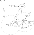
- FIGURE 1 through FIGURE 13 discussed below, and the various embodiments used to describe the principles of the present disclosure in this patent document are by way of illustration only and should not be construed in any way to limit the scope of the disclosure. Those skilled in the art will understand that the principles of the present disclosure may be implemented in any suitably arranged system or device.
- Dotted lines show the approximate extents of the coverage areas 120 and 125, which are shown as approximately circular for the purposes of illustration and explanation only. It should be clearly understood that the coverage areas associated with gNBs, such as the coverage areas 120 and 125, may have other shapes, including irregular shapes, depending upon the configuration of the gNBs and variations in the radio environment associated with natural and man-made obstructions.
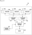
- the transceivers 210a-210n receive, from the antennas 205a-205n, incoming radio frequency (RF) signals, such as signals transmitted by UEs in the network 100.
- the transceivers 210a-210n down-convert the incoming RF signals to generate IF or baseband signals.
- the IF or baseband signals are processed by receive (RX) processing circuitry in the transceivers 210a-210n and/or controller/processor 225, which generates processed baseband signals by filtering, decoding, and/or digitizing the baseband or IF signals.
- the controller/processor 225 may further process the baseband signals.
- the controller/processor 225 can include one or more processors or other processing devices that control the overall operation of the gNB 102.
- the controller/processor 225 could control the reception of UL channel signals and the transmission of DL channel signals by the transceivers 210a-210n in accordance with well-known principles.
- the controller/processor 225 could support additional functions as well, such as more advanced wireless communication functions.
- the controller/processor 225 could support beam forming or directional routing operations in which outgoing/incoming signals from/to multiple antennas 205a-205n are weighted differently to effectively steer the outgoing signals in a desired direction. Any of a wide variety of other functions could be supported in the gNB 102 by the controller/processor 225.
- the controller/processor 225 is also capable of executing programs and other processes resident in the memory 230, such as an OS.
- the controller/processor 225 can move data into or out of the memory 230 as required by an executing process.
- the controller/processor 225 is also coupled to the backhaul or network interface 235.
- the backhaul or network interface 235 allows the gNB 102 to communicate with other devices or systems over a backhaul connection or over a network.
- the interface 235 could support communications over any suitable wired or wireless connection(s).
- the gNB 102 is implemented as part of a cellular communication system (such as one supporting 5G/NR, LTE, or LTE-A)
- the interface 235 could allow the gNB 102 to communicate with other gNBs over a wired or wireless backhaul connection.
- the interface 235 could allow the gNB 102 to communicate over a wired or wireless local area network or over a wired or wireless connection to a larger network (such as the Internet).
- the interface 235 includes any suitable structure supporting communications over a wired or wireless connection, such as an Ethernet or RF transceiver.
- FIGURE 2 illustrates one example of gNB 102
- the gNB 102 could include any number of each component shown in FIGURE 2 .
- various components in FIGURE 2 could be combined, further subdivided, or omitted and additional components could be added according to particular needs.
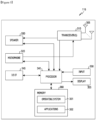
- the UE 116 includes antenna(s) 305, a transceiver(s) 310, and a microphone 320.
- the UE 116 also includes a speaker 330, a processor 340, an input/output (I/O) interface (IF) 345, an input 350, a display 355, and a memory 360.
- the memory 360 includes an operating system (OS) 361 and one or more applications 362.
- the transceiver(s) 310 receives, from the antenna(s) 305, an incoming RF signal transmitted by a gNB of the network 100.
- the transceiver(s) 310 down-converts the incoming RF signal to generate an intermediate frequency (IF) or baseband signal.
- IF or baseband signal is processed by RX processing circuitry in the transceiver(s) 310 and/or processor 340, which generates a processed baseband signal by filtering, decoding, and/or digitizing the baseband or IF signal.
- the RX processing circuitry sends the processed baseband signal to the speaker 330 (such as for voice data) or is processed by the processor 340 (such as for web browsing data).
- TX processing circuitry in the transceiver(s) 310 and/or processor 340 receives analog or digital voice data from the microphone 320 or other outgoing baseband data (such as web data, e-mail, or interactive video game data) from the processor 340.
- the TX processing circuitry encodes, multiplexes, and/or digitizes the outgoing baseband data to generate a processed baseband or IF signal.
- the transceiver(s) 310 up-converts the baseband or IF signal to an RF signal that is transmitted via the antenna(s) 305.
- the processor 340 can include one or more processors or other processing devices and execute the OS 361 stored in the memory 360 in order to control the overall operation of the UE 116.
- the processor 340 could control the reception of DL channel signals and the transmission of UL channel signals by the transceiver(s) 310 in accordance with well-known principles.
- the processor 340 includes at least one microprocessor or microcontroller.
- the processor 340 is also capable of executing other processes and programs resident in the memory 360.
- the processor 340 can move data into or out of the memory 360 as required by an executing process.
- the processor 340 is configured to execute the applications 362 based on the OS 361 or in response to signals received from gNBs or an operator.
- the processor 340 is also coupled to the I/O interface 345, which provides the UE 116 with the ability to connect to other devices, such as laptop computers and handheld computers.
- the I/O interface 345 is the communication path between these accessories and the processor 340.
- the processor 340 is also coupled to the input 350, which includes for example, a touchscreen, keypad, etc., and the display 355.
- the operator of the UE 116 can use the input 350 to enter data into the UE 116.
- the display 355 may be a liquid crystal display, light emitting diode display, or other display capable of rendering text and/or at least limited graphics, such as from web sites.
- the memory 360 is coupled to the processor 340.
- Part of the memory 360 could include a random-access memory (RAM), and another part of the memory 360 could include a Flash memory or other read-only memory (ROM).
- RAM random-access memory
- ROM read-only memory
- FIGURE 3 illustrates one example of UE 116
- various changes may be made to FIGURE 3 .
- various components in FIGURE 3 could be combined, further subdivided, or omitted and additional components could be added according to particular needs.
- the processor 340 could be divided into multiple processors, such as one or more central processing units (CPUs) and one or more graphics processing units (GPUs).
- FIGURE 3 illustrates the UE 116 configured as a mobile telephone or smartphone, UEs could be configured to operate as other types of mobile or stationary devices.
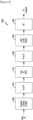
- FIGURE 4 illustrates an example wireless transmit path according to this disclosure.
- a transmit path 400 may be described as being implemented in a gNB (such as the gNB 102). However, it may be understood that the transmit path 400 can be implemented in a UE.
- the transmit path 400 as illustrated in FIGURE 4 includes a channel coding and modulation block 405, a serial-to-parallel (S-to-P) block 410, a size N inverse fast Fourier transform (IFFT) block 415, a parallel-to-serial (P-to-S) block 420, an add cyclic prefix block 425, and an up-converter (UC) 430.
- S-to-P serial-to-parallel
- IFFT inverse fast Fourier transform
- P-to-S parallel-to-serial
- UC up-converter
- the channel coding and modulation block 405 receives a set of information bits, applies coding (such as a low-density parity check (LDPC) coding), and modulates the input bits (such as with quadrature phase shift keying (QPSK) or quadrature amplitude modulation (QAM)) to generate a sequence of frequency-domain modulation symbols.
- coding such as a low-density parity check (LDPC) coding
- modulates the input bits such as with quadrature phase shift keying (QPSK) or quadrature amplitude modulation (QAM) to generate a sequence of frequency-domain modulation symbols.
- QPSK quadrature phase shift keying
- QAM quadrature amplitude modulation
- the serial-to-parallel block 410 converts (such as de-multiplexes) the serial modulated symbols to parallel data in order to generate N parallel symbol streams, where N is the IFFT/FFT size used in the gNB 102 and the UE 116.
- the size N IFFT block 415 performs an IFFT operation on the N parallel symbol streams to generate time-domain output signals.
- the parallel-to-serial block 420 converts (such as multiplexes) the parallel time-domain output symbols from the size N IFFT block 415 in order to generate a serial time-domain signal.
- the add cyclic prefix block 425 inserts a cyclic prefix to the time-domain signal.
- the up-converter 430 modulates (such as up-converts) the output of the add cyclic prefix block 425 to an RF frequency for transmission via a wireless channel.
- the signal may also be filtered at baseband before conversion to the RF frequency.
- a transmitted RF signal from the gNB 102 arrives at the UE 116 after passing through the wireless channel, and reverse operations to those at the gNB 102 are performed at the UE 116.
- FIGURE 5 illustrates an example wireless receive path according to this disclosure.
- a receive path 500 may be described as being implemented in a UE (such as a UE 116). However, it may be understood that the receive path 500 can be implemented in a gNB.
- the receive path 500 is configured to support the codebook design and structure for systems having 2D antenna arrays as described in embodiments of the present disclosure.
- the receive path 500 as illustrated in FIGURE 5 includes a down-converter (DC) 555, a remove cyclic prefix block 560, a serial-to-parallel (S-to-P) block 565, a size N fast Fourier transform (FFT) block 570, a parallel-to-serial (P-to-S) block 575, and a channel decoding and demodulation block 580.
- DC down-converter
- S-to-P serial-to-parallel
- FFT size N fast Fourier transform
- P-to-S parallel-to-serial
- the downconverter 555 down-converts the received signal to a baseband frequency
- the remove cyclic prefix block 560 removes the cyclic prefix to generate a serial time-domain baseband signal.
- the serial-to-parallel block 565 converts the time-domain baseband signal to parallel time domain signals.
- the size N FFT block 570 performs an FFT algorithm to generate N parallel frequency-domain signals.
- the parallel-to-serial block 575 converts the parallel frequency-domain signals to a sequence of modulated data symbols.
- the channel decoding and demodulation block 580 demodulates and decodes the modulated symbols to recover the original input data stream.
- the first TCI state and/or the TCI state with the lowest TCI state ID value indicated in the DCI for beam indication could correspond to the first entry/TRP in the list/set/pool of TRP-specific ID/index values
- the second TCI state and/or the TCI state with the second lowest TCI state ID value indicated in the DCI for beam indication could correspond to the second entry/TRP in the list/set/pool of TRP-specific ID/index values, and so on
- the last TCI state and/or the TCI state with the highest TCI state ID value indicated in the DCI for beam indication could correspond to the last entry/TRP in the list/set/pool of TRP-specific ID/index values.
- the UE could be first higher layer configured by the network a list/set/pool of CORESETPoolIndex values - e.g., a set of two CORESETPoolIndex values 0 and 1. The UE could then receive from the network one or more MAC CE activation commands/bitmaps to activate one or more CORESETPoolIndex values from the higher layer configured list/set/pool of CORESETPoolIndex values.
- the first TCI state and/or the TCI state with the lowest TCI state ID value indicated in the DCI for beam indication could correspond to the lowest/lowest MAC CE activated CORESETPoolIndex value such as "0”
- the second TCI state and/or the TCI state with the second lowest TCI state ID value indicated in the DCI for beam indication could correspond to the second lowest/second lowest MAC CE activated CORESETPoolIndex value such as "1”
- the last TCI state and/or the TCI state with the highest TCI state ID value indicated in the DCI for beam indication could correspond to the highest/highest MAC CE activated CORESETPoolIndex value such as "N-1".
- the UE could be explicitly indicated by the network, e.g., via higher layer RRC signaling and/or MAC CE command and/or dynamic DCI signaling, the exact association/mapping between the DCIs for beam indication (and therefore, the TCI states/beams indicated therein) and the TRPs in the multi-TRP system.
- the UE could be first higher layer configured by the network a list/set/pool of TRP-specific ID/index values such as PCIs.
- the UE could be first higher layer configured by the network a list/set/pool of TRP-specific ID/index values such as PCIs. The UE could then receive from the network one or more MAC CE activation commands/bitmaps to activate one or more TRP-specific ID/index values from the higher layer configured list/set/pool of TRP-specific ID/index values.
- the DCI for beam indication associated with the lowest CORESETPoolIndex value (indicated in the corresponding higher layer parameter ControlResourceSet) and/or the DCI for beam indication indicating the TCI state with the lowest TCI state ID value could correspond to the first MAC CE(s)/bitmap(s) activated TRP-specific ID/index values
- the DCI for beam indication associated with the second lowest CORESETPoolIndex value (indicated in the corresponding higher layer parameter ControlResourceSet) and/or the DCI for beam indication indicating the TCI state with the second lowest TCI state ID value could correspond to the second MAC CE(s)/bitmap(s) activated TRP-specific ID/index values, and so on
- the DCI for beam indication associated with the highest CORESETPoolIndex value (indicated in the corresponding higher layer parameter ControlResourceSet) and/or the DCI for beam indication indicating the TCI state with the highest TCI state ID value could correspond to the last MAC CE(s)/bit
- a DCI for beam indication could include/comprise/incorporate at least one ID/index value.
- this ID/index value could be a (absolute) TRP-specific ID/index value such as PCI value, TRP ID value, TRP index value and etc., based on a list/set/pool of TRP-specific ID/index values, e.g., higher layer configured to the UE and/or higher layer configured to the UE and activated by one or more MAC CE activation commands/bitmaps.
- each TCI state contains at least a QCL source RS with a QCL type, e.g., QCL-typeA/B/C/D.
- the UE could then receive from the network one or more MAC CE activation commands activating one or more TCI states from the higher layer configured list/pool of TCI states, e.g., up to eight TCI states could be activated by a MAC CE activation command.
- the UE could receive from the network one or more DCIs to indicate one or more beam(s) (i.e., the Rel. 17 unified TCI state(s)) from the MAC CE activated TCI state(s)/beam(s) for UE-dedicated reception on PDSCH/PDCCH or dynamic-grant/configured-grant based PUSCH and all of dedicated PUCCH resources associated with one or more TRPs in a multi-TRP system.
- beam(s) i.e., the Rel. 17 unified TCI state(s)
- the UE could receive from the network a single DCI to indicate M'>1 Rel. 17 unified TCI states/beams (e.g., M'>1 joint DL and UL TCI states or M'>1 separate UL TCI states) from the MAC CE activated TCI states/beams for the same PUSCH(s)/PUCCH(s) transmitted to/associated with different TRPs in the multi-TRP system.
- M'>1 joint DL and UL TCI states or M'>1 separate UL TCI states activated TCI states/beams for the same PUSCH(s)/PUCCH(s) transmitted to/associated with different TRPs in the multi-TRP system.
- the Rel. 17 unified TCI state indicated in the DCI for beam indication could be at least one of: (1) a DL TCI state; (2) an UL TCI state; (3) a joint DL and UL TCI state; and (4) separate DL TCI state and UL TCI state.
- the association/mapping between the DCI(s) indicated TCI state(s)/beam(s) - from the MAC CE activated TCI state(s)/beam(s) - and the TRPs in the multi-TRP system needs to be specified. There could be various means to associate/map the DCI(s) indicated TCI state(s)/beam(s) - from the MAC CE activated TCI state(s)/beam(s) - and the TRPs in the multi-TRP system.
- the UE could be explicitly indicated by the network, e.g., via higher layer RRC signaling and/or MAC CE command and/or dynamic DCI signaling, the exact association/mapping between the DCI indicated TCI states/beams (selected from the MAC CE activated TCI states/beams) and the TRPs in the multi-TRP system.
- the UE could be first higher layer configured by the network a list/set/pool of TRP-specific ID/index values such as PCIs.
- the first TCI state and/or the TCI state with the lowest TCI state ID value indicated in the DCI for beam indication could correspond to the first entry/TRP in the list/set/pool of TRP-specific ID/index values
- the second TCI state and/or the TCI state with the second lowest TCI state ID value indicated in the DCI for beam indication could correspond to the second entry/TRP in the list/set/pool of TRP-specific ID/index values, and so on
- the last TCI state and/or the TCI state with the highest TCI state ID value indicated in the DCI for beam indication could correspond to the last entry/TRP in the list/set/pool of TRP-specific ID/index values.
- the UE could be first higher layer configured by the network a list/set/pool of TRP-specific ID/index values such as PCIs. The UE could then receive from the network one or more MAC CE activation commands/bitmaps to activate one or more TRP-specific ID/index values from the higher layer configured list/set/pool of TRP-specific ID/index values.
- the first TCI state and/or the TCI state with the lowest TCI state ID value indicated in the DCI for beam indication could correspond to the first MAC CE(s)/bitmap(s) activated TRP-specific ID/index value
- the second TCI state and/or the TCI state with the second lowest TCI state ID value indicated in the DCI for beam indication could correspond to the second MAC CE(s)/bitmap(s) activated TRP-specific ID/index value, and so on
- the last TCI state and/or the TCI state with the highest TCI state ID value indicated in the DCI for beam indication could correspond to the last MAC CE(s)/bitmap(s) activated TRP-specific ID/index value.
- the UE could be implicitly indicated by the network the association/mapping between the DCI indicated TCI states/beams (selected from the MAC CE activated TCI states/beams) and the TRPs in the multi-TRP system.
- the UE could be higher layer configured by the network a list/set/pool of TRP-specific ID/index values such as PCIs.
- the UE could also receive from the network one or more MAC CE activation commands/bitmaps to activate one or more TRP-specific ID/index values from the higher layer configured list/set/pool of TRP-specific ID/index values.
- the first TCI state and/or the TCI state with the lowest TCI state ID value indicated in the DCI for beam indication could correspond to the TRP with the lowest/lowest MAC CE activated TRP-specific ID/index value such as the lowest PCI value and/or the first TRP (e.g., TRP #1)
- the second TCI state and/or the TCI state with the second lowest TCI state ID value indicated in the DCI for beam indication could correspond to the TRP with the second lowest/second lowest MAC CE activated TRP-specific ID/index value such as the second lowest PCI value and/or the second TRP (e.g., TRP #2), and so on
- the last TCI state and/or the TCI state with the highest TCI state ID value indicated in the DCI for beam indication could correspond to the TRP with the highest/highest MAC CE activated TRP-specific ID/index value such as the highest PCI value and/or the last TRP (e.g., TRP #N').
- the first TCI state and/or the TCI state with the lowest TCI state ID value indicated in the DCI for beam indication could correspond to the TRP with the highest/highest MAC CE activated TRP-specific ID/index value such as the highest PCI value and/or the last TRP (e.g., TRP #N')
- the second TCI state and/or the TCI state with the second lowest TCI state ID value indicated in the DCI for beam indication could correspond to the TRP with the second highest/second highest MAC CE activated TRP-specific ID/index value such as the second highest PCI value and/or the second last TRP (e.g., TRP #N'-1), and so on
- the last TCI state and/or the TCI state with the highest TCI state ID value indicated in the DCI for beam indication could correspond to the TRP with the lowest/lowest MAC CE activated TRP-specific ID/index value such as the lowest PCI value and/or the first TRP (e.g., TRP #1).
- TRP #1 the lowest
- the UE could be explicitly indicated by the network, e.g., via higher layer RRC signaling and/or MAC CE command and/or dynamic DCI signaling, the exact association/mapping between the DCI indicated TCI states/beams (selected from the MAC CE activated TCI states/beams) and the CORESETPoolIndex values.
- the UE could be first higher layer configured by the network a list/set/pool of CORESETPoolIndex values - e.g., a set of two CORESETPoolIndex values 0 and 1.
- the first TCI state and/or the TCI state with the lowest TCI state ID value indicated in the DCI for beam indication could correspond to the first entry/CORESETPoolIndex value in the list/set/pool of CORESETPoolIndex values
- the second TCI state and/or the TCI state with the second lowest TCI state ID value indicated in the DCI for beam indication could correspond to the second entry/CORESETPoolIndex value in the list/set/pool of CORESETPoolIndex values, and so on
- the last TCI state and/or the TCI state with the highest TCI state ID value indicated in the DCI for beam indication could correspond to the last entry/CORESETPoolIndex value in the list/set/pool of CORESETPoolIndex values.
- the UE could be first higher layer configured by the network a list/set/pool of CORESETPoolIndex values - e.g., a set of two CORESETPoolIndex values 0 and 1. The UE could then receive from the network one or more MAC CE activation commands/bitmaps to activate one or more CORESETPoolIndex values from the higher layer configured list/set/pool of CORESETPoolIndex values.
- the first TCI state and/or the TCI state with the lowest TCI state ID value indicated in the DCI for beam indication could correspond to the first MAC CE(s)/bitmap(s) activated CORESETPoolIndex value
- the second TCI state and/or the TCI state with the second lowest TCI state ID value indicated in the DCI for beam indication could correspond to the second MAC CE(s)/bitmap(s) activated CORESETPoolIndex value, and so on
- the last TCI state and/or the TCI state with the highest TCI state ID value indicated in the DCI for beam indication could correspond to the last MAC CE(s)/bitmap(s) activated CORESETPoolIndex value.
- the UE could be implicitly indicated by the network the association/mapping between the DCI indicated TCI states/beams (selected from the MAC CE activated TCI states/beams) and the CORESETPoolIndex values.
- the UE could be higher layer configured by the network a list/set/pool of CORESETPoolIndex values - e.g., a set of two CORESETPoolIndex values 0 and 1.
- the UE could also receive from the network one or more MAC CE activation commands/bitmaps to activate one or more CORESETPoolIndex values from the higher layer configured list/set/pool of CORESETPoolIndex values.
- the first TCI state and/or the TCI state with the lowest TCI state ID value indicated in the DCI for beam indication could correspond to the lowest/lowest MAC CE activated CORESETPoolIndex value such as "0”
- the second TCI state and/or the TCI state with the second lowest TCI state ID value indicated in the DCI for beam indication could correspond to the second lowest/second lowest MAC CE activated CORESETPoolIndex value such as "1", and so on
- the last TCI state and/or the TCI state with the highest TCI state ID value indicated in the DCI for beam indication could correspond to the highest/highest MAC CE activated CORESETPoolIndex value such as "N-1".
- the first TCI state and/or the TCI state with the lowest TCI state ID value indicated in the DCI for beam indication could correspond to the highest/highest MAC CE activated CORESETPoolIndex value
- the second TCI state and/or the TCI state with the second lowest TCI state ID value indicated in the DCI for beam indication could correspond to the second highest/second highest MAC CE activated CORESETPoolIndex value, and so on
- the last TCI state and/or the TCI state with the highest TCI state ID value indicated in the DCI for beam indication could correspond to the lowest/lowest MAC CE activated CORESETPoolIndex value.
- Other implicit indication methods of the association/mapping between the N'>1 DCI indicated TCI states/beams (selected from the MAC CE activated TCI states/beams) and the CORESETPoolIndex values are also possible.
- a TCI state selected from the MAC CE activated TCI states/beams, e.g., the higher layer parameter TCI-State, indicated in the MAC CE command for beam indication could include/comprise/incorporate at least one ID/index value.
- this ID/index value could be a (absolute) TRP-specific ID/index value such as PCI value, TRP ID value, TRP index value and etc., based on a list/set/pool of TRP-specific ID/index values, e.g., higher layer configured to the UE and/or higher layer configured to the UE and activated by one or more MAC CE activation commands/bitmaps.
- this ID/index value could be an (relative) index within the list/set/pool of TRP-specific ID/index values, e.g., higher layer configured to the UE and/or higher layer configured to the UE and activated by one or more MAC CE activation commands/bitmaps.
- this ID/index value could be a CORESETPoolIndex value.
- the UE could be explicitly indicated by the network, e.g., via higher layer RRC signaling and/or MAC CE command and/or dynamic DCI signaling, the exact association/mapping between the DCIs for beam indication (and therefore, the TCI states/beams indicated therein - selected from the MAC CE activated TCI states/beams) and the TRPs in the multi-TRP system.
- the UE could be first higher layer configured by the network a list/set/pool of TRP-specific ID/index values such as PCIs.
- the DCI for beam indication associated with the lowest CORESETPoolIndex value (indicated in the corresponding higher layer parameter ControlResourceSet) and/or the DCI for beam indication indicating the TCI state with the lowest TCI state ID value could correspond to the first entry/TRP in the list/set/pool of TRP-specific ID/index values
- the DCI for beam indication associated with the second lowest CORESETPoolIndex value (indicated in the corresponding higher layer parameter ControlResourceSet) and/or the DCI for beam indication indicating the TCI state with the second lowest TCI state ID value could correspond to the second entry/TRP in the list/set/pool of TRP-specific ID/index values, and so on
- the DCI for beam indication associated with the highest CORESETPoolIndex value (indicated in the corresponding higher layer parameter ControlResourceSet) and/or the DCI for beam indication indicating the TCI state with the highest TCI state ID value could correspond to the last entry/TRP in the list/set/pool of
- the UE could be first higher layer configured by the network a list/set/pool of TRP-specific ID/index values such as PCIs. The UE could then receive from the network one or more MAC CE activation commands/bitmaps to activate one or more TRP-specific ID/index values from the higher layer configured list/set/pool of TRP-specific ID/index values.
- the DCI for beam indication associated with the lowest CORESETPoolIndex value (indicated in the corresponding higher layer parameter ControlResourceSet) and/or the DCI for beam indication indicating the TCI state with the lowest TCI state ID value could correspond to the first MAC CE(s)/bitmap(s) activated TRP-specific ID/index values
- the DCI for beam indication associated with the second lowest CORESETPoolIndex value (indicated in the corresponding higher layer parameter ControlResourceSet) and/or the DCI for beam indication indicating the TCI state with the second lowest TCI state ID value could correspond to the second MAC CE(s)/bitmap(s) activated TRP-specific ID/index values, and so on
- the DCI for beam indication associated with the highest CORESETPoolIndex value (indicated in the corresponding higher layer parameter ControlResourceSet) and/or the DCI for beam indication indicating the TCI state with the highest TCI state ID value could correspond to the last MAC CE(s)/bit
- the UE could be implicitly indicated by the network the association/mapping between the DCIs for beam indication (and therefore, the TCI states/beams indicated therein - selected from the MAC CE activated TCI states/beams) and the TRPs in the multi-TRP system.
- the UE could be higher layer configured by the network a list/set/pool of TRP-specific ID/index values such as PCIs.
- the UE could also receive from the network one or more MAC CE activation commands/bitmaps to activate one or more TRP-specific ID/index values from the higher layer configured list/set/pool of TRP-specific ID/index values.
- the DCI for beam indication associated with the lowest CORESETPoolIndex value (indicated in the corresponding higher layer parameter ControlResourceSet) and/or the DCI for beam indication indicating the lowest TCI state ID value could correspond to the TRP with the lowest/lowest MAC CE activated TRP-specific ID/index value such as the lowest PCI value and/or the first TRP (e.g., TRP #1), the DCI for beam indication associated with the second lowest CORESETPoolIndex value (indicated in the corresponding higher layer parameter ControlResourceSet) and/or the DCI for beam indication indicating the second lowest TCI state ID value could correspond to the TRP with the second lowest/second lowest MAC CE activated TRP-specific ID/index value such as the second lowest PCI value and/or the second TRP (e.g., TRP #2), and so on, and the DCI for beam indication associated with the highest CORESETPoolIndex value (indicated in the corresponding higher layer parameter ControlResourceSet) and
- the DCI for beam indication associated with the lowest CORESETPoolIndex value (indicated in the corresponding higher layer parameter ControlResourceSet) and/or the DCI for beam indication indicating the lowest TCI state ID value could correspond to the TRP with the highest/highest MAC CE activated TRP-specific ID/index value such as the highest PCI value and/or the last TRP (e.g., TRP #N'), the DCI for beam indication associated with the second lowest CORESETPoolIndex value (indicated in the corresponding higher layer parameter ControlResourceSet) and/or the DCI for beam indication indicating the second lowest TCI state ID value could correspond to the TRP with the second highest/second highest MAC CE activated TRP-specific ID/index value such as the second highest PCI value and/or the second last TRP (e.g., TRP #N'-1), and so on, and the DCI for beam indication associated with the highest CORESETPoolIndex value (indicated in the corresponding higher layer
- the UE may transmit K nominal PUSCH repetitions according to (1) the RSs configured with qcl-Type set to "typeD" corresponding to the QCL assumptions in the indicated M>1 joint DL and UL TCI states or M>1 separate UL TCI states or M>1 joint DL and UL TCI states and separate UL TCI states, and (2) the association between the M>1 joint DL and UL TCI states or M>1 separate UL TCI states or M>1 joint DL and UL TCI states and separate UL TCI states and separate UL TCI states, and (2) the association between the M>1 joint DL and UL TCI states or M>1 separate UL TCI states or M>1 joint DL and UL TCI states and separate UL TCI states,
- the UE could determine the RS resource index q d providing a periodic RS resource configured with qcl-Type set to "typeD" corresponding to the QCL assumption in the indicated separate DL TCI state.
- the UE could determine the RS resource index q d providing a periodic RS resource configured with qcl-Type set to "typeD" corresponding to the QCL assumption in one of the indicated N>1 separate DL TCI states - e.g., the indicated separate DL TCI state associated with the k-th slot in the K> 1 consecutive slots ( k ⁇ 1,..., K ⁇ ) following those specified in examples of the present disclosure.
- the UE may transmit K nominal PUSCH repetitions according to (1) the RSs configured with qcl-Type set to "typeD" corresponding to the QCL assumptions in the indicated N>1 separate DL TCI states, and (2) the association between the N>1 separate DL TCI states and the K>1 nominal PUSCH repetitions following those specified in examples of the present disclosure by considering nominal repetition
- the UE could determine the RS resource index q d providing a periodic RS resource configured with qcl-Type set to "typeD" corresponding to the QCL assumption in one of the indicated N>1 separate DL TCI state - e.g., the indicated separate DL TCI state associated with the k-th nominal PDSCH repetition in the K> 1 nominal PDSCH repetitions ( k ⁇ 1,..., K ⁇ ) following those specified in examples of the present disclosure by considering nominal repetitions instead of slots.
- a UE When a UE is provided by the network, e.g., via unified TCI states activation MAC CE and/or one or more TCI codepoints of one or more TCI fields in the beam indication DCI (e.g., DCI format 1_1/1_2 with or without DL assignment), M>1 joint DL and UL Rel. 17 unified TCI states or M>1 separate UL Rel.
- DCI e.g., DCI format 1_1/1_2 with or without DL assignment
- the UE is indicated/configured/provided by the network, e.g., in higher layer RRC signalling/parameter and/or MAC CE command and/or dynamic DCI based L1 signalling (e.g., the higher layer parameter PUCCH-Config that configures the PUCCH), an indicator (e.g., a two-bit indicator) set to '0' or '1' or '00' or '01' or '10' or '11' indicating that one or both of the indicated (UL or joint) TCI states/pairs of TCI states (e.g., in the beam indication DCI 1_1/1_2 via one or more TCI codepoints of one or more TCI fields) are used/applied for the PUCCH transmission(s), and when the UE is configured a number of slots N PUCCH repeat , for repetitions of a PUCCH transmission, the UE
- the PUCCH(s)/PUSCH(s) could be repeatedly transmitted from the UE to the network using different time domain resources (e.g., different symbols, mini-slots, slots, etc.) - TDM strategy, and/or different frequency domain resources (e.g., different resource elements, resource blocks, etc.) - FDM strategy, and/or different spatial domain filters (i.e., different beams) - SDM strategy.
- different time domain resources e.g., different symbols, mini-slots, slots, etc.
- frequency domain resources e.g., different resource elements, resource blocks, etc.
- different spatial domain filters i.e., different beams
- the present disclosure provides various design aspects/enhancements for uplink power control, wherein the UE could transmit the same PUSCH(s)/PUCCH(s) to different TRPs using different time domain resources and/or different frequency domain resources and/or different spatial domain filters.
- the indicated TCI state could be at least one of: (1) a DL TCI state and/or its corresponding/associated TCI state ID; (2) an UL TCI state and/or its corresponding/associated TCI state ID; (3) a joint DL and UL TCI state and/or its corresponding/associated TCI state ID; and (4) separate DL TCI state and UL TCI state and/or their corresponding/associated TCI state ID(s).
- a MAC CE could be used to indicate to the UE a beam (i.e., a TCI state and/or a TCI state ID) for the transmission/reception of a PDCCH or a PDSCH and in another example, a DCI could be used to indicate to the UE a beam (i.e., a TCI state and/or a TCI state ID) for the transmission/reception of a PDCCH or a PDSCH.
- a DL related DCI (e.g., DCI format 1_0, DCI format 1_1 or DCI format 1_2) could be used to indicate to the UE a beam (i.e., a TCI state and/or a TCI state ID) for the transmission/reception of a PDCCH or a PDSCH, wherein the DL related DCI may or may not include a DL assignment.
- an UL related DCI (e.g., DCI format 0_0, DCI format 0_1, DCI format 0_2) could be used to indicate to the UE a beam (i.e., a TCI state and/or a TCI state ID) for the transmission/reception of a PDCCH or a PDSCH, wherein the UL related DCI may or may not include an UL scheduling grant.
- a beam i.e., a TCI state and/or a TCI state ID
- a custom/purpose designed DCI format could be used to indicate to the UE a beam (i.e., a TCI state and/or a TCI state ID) for the transmission/reception of a PDCCH or a PDSCH.
- the unified or master or main TCI state can be one of: (1) in case of joint TCI state indication, wherein a same beam is used for DL and UL channels, a joint TCI state that can be used at least for UE-dedicated DL channels and UE-dedicated UL channels; (2) in case of separate TCI state indication, wherein different beams are used for DL and UL channels, a DL TCI state can be used at least for UE-dedicated DL channels; and (3) in case of separate TCI state indication, wherein different beams are used for DL and UL channels, a UL TCI state can be used at least for UE-dedicated UL channels.
- the unified (master or main) TCI state is TCI state of UE-dedicated reception on PDSCH/PDCCH or dynamic-grant/configured-grant based PUSCH and all of dedicated PUCCH resources.
- the TCI state/beam indication for the PUSCH(s)/PUCCH(s) repetition in a multi-TRP system is discussed under the Rel. 17 unified TCI framework, wherein one or more DL/UL TCI states could be separately/jointly indicated in various channels such as MAC CE and/or DCI (e.g., DCI format 1_1 or 1_2 with or without DL assignment).
- the UE could transmit the same PUSCH(s)/PUCCH(s) to different TRPs in the multi-TRP system using different time domain resources and/or different frequency domain resources and/or different spatial domain filters.
- the UE could be first higher layer configured by the network, e.g., via the higher layer RRC signaling, a list/pool of N_tci TCI states.
- Each TCI state contains at least a QCL source RS with a QCL type, e.g., QCL-typeA/B/C/D.
- the UE could then receive from the network one or more MAC CE commands to indicate one or more beam(s) (i.e., the Rel.
- the UE could receive from the network a single MAC CE command for beam indication to indicate M>1 Rel.
- 17 unified TCI states/beams e.g., M>1 joint DL and UL TCI states or M>1 separate UL TCI states
- PUSCH(s)/PUCCH(s) transmitted to/associated with different TRPs in the multi-TRP system.
- the MAC CE for beam indication could include at least a Rel. 17 unified TCI state ID.
- the Rel. 17 unified TCI state corresponding to the TCI state ID could be at least one of: (1) a DL TCI state; (2) an UL TCI state; (3) a joint DL and UL TCI state; and (4) separate DL TCI state and UL TCI state.
- the association/mapping between the TCI state(s)/beam(s) indicated in the MAC CE command(s) and the TRPs in the multi-TRP system needs to be specified. There could be various means to associate/map the TCI state(s)/beam(s) indicated in the MAC CE command(s) for beam indication and the TRPs in the multi-TRP system.
- the UE could be explicitly indicated by the network, e.g., via higher layer RRC signaling and/or MAC CE command and/or dynamic DCI signaling, the exact association/mapping between the TCI states/beams indicated in the MAC CE command for beam indication and the TRPs in the multi-TRP system.
- the UE could be first higher layer configured by the network a list/set/pool of TRP-specific ID/index values such as PCIs.
- the first TCI state and/or the TCI state with the lowest TCI state ID value indicated in the MAC CE command for beam indication could correspond to the first entry/TRP in the list/set/pool of TRP-specific ID/index values
- the second TCI state and/or the TCI state with the second lowest TCI state ID value indicated in the MAC CE command for beam indication could correspond to the second entry/TRP in the list/set/pool of TRP-specific ID/index values, and so on
- the last TCI state and/or the TCI state with the highest TCI state ID value indicated in the MAC CE command for beam indication could correspond to the last entry/TRP in the list/set/pool of TRP-specific ID/index values.
- the UE could be first higher layer configured by the network a list/set/pool of TRP-specific ID/index values such as PCIs. The UE could then receive from the network one or more MAC CE activation commands/bitmaps to activate one or more TRP-specific ID/index values from the higher layer configured list/set/pool of TRP-specific ID/index values.
- the first TCI state and/or the TCI state with the lowest TCI state ID value indicated in the MAC CE command for beam indication could correspond to the first MAC CE(s)/bitmap(s) activated TRP-specific ID/index value
- the second TCI state and/or the TCI state with the second lowest TCI state ID value indicated in the MAC CE command for beam indication could correspond to the second MAC CE(s)/bitmap(s) activated TRP-specific ID/index value, and so on
- the last TCI state and/or the TCI state with the highest TCI state ID value indicated in the MAC CE command for beam indication could correspond to the last MAC CE(s)/bitmap(s) activated TRP-specific ID/index value.
- the UE could be implicitly indicated by the network the association/mapping between the TCI states/beams indicated in the MAC CE command for beam indication and the TRPs in the multi-TRP system.
- the UE could be higher layer configured by the network a list/set/pool of TRP-specific ID/index values such as PCIs.
- the UE could also receive from the network one or more MAC CE activation commands/bitmaps to activate one or more TRP-specific ID/index values from the higher layer configured list/set/pool of TRP-specific ID/index values.
- the first TCI state and/or the TCI state with the lowest TCI state ID value indicated in the MAC CE command for beam indication could correspond to the TRP with the lowest/lowest MAC CE activated TRP-specific ID/index value such as the lowest PCI value and/or the first TRP (e.g., TRP #1), the second TCI state and/or the TCI state with the second lowest TCI state ID value indicated in the MAC CE command for beam indication could correspond to the TRP with the second lowest/second lowest MAC CE activated TRP-specific ID/index value such as the second lowest PCI value and/or the second TRP (e.g., TRP #2), and so on, and the last TCI state and/or the TCI state with the highest TCI state ID value indicated in the MAC CE command for beam indication could correspond to the TRP with the highest/highest MAC CE activated TRP-specific ID/index value such as the highest PCI value and/or the last TRP (e.g., TRP #N).
- the first TCI state and/or the TCI state with the lowest TCI state ID value indicated in the MAC CE command for beam indication could correspond to the TRP with the highest/highest MAC CE activated TRP-specific ID/index value such as the highest PCI value and/or the last TRP (e.g., TRP #N)
- the second TCI state and/or the TCI state with the second lowest TCI state ID value indicated in the MAC CE command for beam indication could correspond to the TRP with the second highest/second highest MAC CE activated TRP-specific ID/index value such as the second highest PCI value and/or the second last TRP (e.g., TRP #N-1), and so on
- the last TCI state and/or the TCI state with the highest TCI state ID value indicated in the MAC CE command for beam indication could correspond to the TRP with the lowest/lowest MAC CE activated TRP-specific ID/index value such as the lowest PCI value and/or the first TRP (e.g., TRP #1).
- the UE could be explicitly indicated by the network, e.g., via higher layer RRC signaling and/or MAC CE command and/or dynamic DCI signaling, the exact association/mapping between the TCI states/beams indicated in the MAC CE command for beam indication and the CORESETPoolIndex values.
- the UE could be first higher layer configured by the network a list/set/pool of CORESETPoolIndex values - e.g., a set of two CORESETPoolIndex values 0 and 1.
- the first TCI state and/or the TCI state with the lowest TCI state ID value indicated in the MAC CE command for beam indication could correspond to the first entry/CORESETPoolIndex value in the list/set/pool of CORESETPoolIndex values
- the second TCI state and/or the TCI state with the second lowest TCI state ID value indicated in the MAC CE command for beam indication could correspond to the second entry/CORESETPoolIndex value in the list/set/pool of CORESETPoolIndex values, and so on
- the last TCI state and/or the TCI state with the highest TCI state ID value indicated in the MAC CE command for beam indication could correspond to the last entry/CORESETPoolIndex value in the list/set/pool of CORESETPoolIndex values.
- the UE could be first higher layer configured by the network a list/set/pool of CORESETPoolIndex values - e.g., a set of two CORESETPoolIndex values 0 and 1. The UE could then receive from the network one or more MAC CE activation commands/bitmaps to activate one or more CORESETPoolIndex values from the higher layer configured list/set/pool of CORESETPoolIndex values.
- the first TCI state and/or the TCI state with the lowest TCI state ID value indicated in the MAC CE command for beam indication could correspond to the first MAC CE(s)/bitmap(s) activated CORESETPoolIndex value
- the second TCI state and/or the TCI state with the second lowest TCI state ID value indicated in the MAC CE command for beam indication could correspond to the second MAC CE(s)/bitmap(s) activated CORESETPoolIndex value, and so on
- the last TCI state and/or the TCI state with the highest TCI state ID value indicated in the MAC CE command for beam indication could correspond to the last MAC CE(s)/bitmap(s) activated CORESETPoolIndex value.
- the first TCI state and/or the TCI state with the lowest TCI state ID value indicated in the MAC CE command for beam indication could correspond to the lowest/lowest MAC CE activated CORESETPoolIndex value such as "0”
- the second TCI state and/or the TCI state with the second lowest TCI state ID value indicated in the MAC CE command for beam indication could correspond to the second lowest/second lowest MAC CE activated CORESETPoolIndex value such as "1”
- the last TCI state and/or the TCI state with the highest TCI state ID value indicated in the MAC CE command for beam indication could correspond to the highest/highest MAC CE activated CORESETPoolIndex value such as "N-1".
- this ID/index value could be an (relative) index within the list/set/pool of TRP-specific ID/index values, e.g., higher layer configured to the UE and/or higher layer configured to the UE and activated by one or more MAC CE activation commands/bitmaps.
- this ID/index value could be a CORESETPoolIndex value.
- a unique entity ID/index could be included/incorporated in each MAC CE command for beam indication.
- the UE could be explicitly indicated by the network, e.g., via higher layer RRC signaling and/or MAC CE command and/or dynamic DCI signaling, the exact association/mapping between the MAC CE commands for beam indication (and therefore, the TCI states/beams indicated therein) and the TRPs in the multi-TRP system.
- the UE could be first higher layer configured by the network a list/set/pool of TRP-specific ID/index values such as PCIs.
- the first MAC CE command for beam indication in the list/set/pool of N>1 MAC CE commands for beam indication and/or the MAC CE command for beam indication indicating the lowest entity ID/index value and/or the MAC CE command for beam indication indicating the TCI state with the lowest TCI state ID value could correspond to the first entry/TRP in the list/set/pool of TRP-specific ID/index values
- the second MAC CE command for beam indication in the list/set/pool of N>1 MAC CE commands for beam indication and/or the MAC CE command for beam indication indicating the second lowest entity ID/index value and/or the MAC CE command for beam indication indicating the TCI state with the second lowest TCI state ID value could correspond to the second entry/TRP in the list/set/pool of TRP-specific ID/index values, and so on
- the UE could be first higher layer configured by the network a list/set/pool of TRP-specific ID/index values such as PCIs. The UE could then receive from the network one or more MAC CE activation commands/bitmaps to activate one or more TRP-specific ID/index values from the higher layer configured list/set/pool of TRP-specific ID/index values.
- the first MAC CE command for beam indication in the list/set/pool of N>1 MAC CE commands for beam indication and/or the MAC CE command indicating the lowest entity ID/index value and/or the MAC CE command for beam indication indicating the TCI state with the lowest TCI state ID value could correspond to the first MAC CE(s)/bitmap(s) activated TRP-specific ID/index values
- the second MAC CE command for beam indication in the list/set/pool of N>1 MAC CE commands for beam indication and/or the MAC CE command for beam indication indicting the second lowest entity ID/index value and/or the MAC CE command for beam indication indicating the TCI state with the second lowest TCI state ID value could correspond to the second MAC CE(s)/bitmap(s) activated TRP-specific ID/index values, and so on
- the UE could be implicitly indicated by the network the association/mapping between the MAC CE commands for beam indication (and therefore, the TCI states/beams indicated therein) and the TRPs in the multi-TRP system.
- the UE could be higher layer configured by the network a list/set/pool of TRP-specific ID/index values such as PCIs.
- the UE could also receive from the network one or more MAC CE activation commands/bitmaps to activate one or more TRP-specific ID/index values from the higher layer configured list/set/pool of TRP-specific ID/index values.
- the first MAC CE command for beam indication in the list/set/pool of N>1 MAC CE commands for beam indication and/or the MAC CE command for beam indication indicating the lowest entity ID/index value and/or the MAC CE command for beam indication indicating the lowest TCI state ID value could correspond to the TRP with the lowest/lowest MAC CE activated TRP-specific ID/index value such as the lowest PCI value and/or the first TRP (e.g., TRP #1)
- the second MAC CE command for beam indication in the list/set/pool of N>1 MAC CE commands for beam indication and/or the MAC CE command for beam indication indicating the second lowest entity ID/index value and/or the MAC CE command for beam indication indicating the second lowest TCI state ID value could correspond to the TRP with the second lowest/second lowest MAC CE activated TRP-specific ID/index value such as the second lowest PCI value and/or the second TRP (e.g., TRP #2), and so on, and the last MAC CE command for beam indication in the
- the first MAC CE command for beam indication in the list/set/pool of N>1 MAC CE commands for beam indication and/or the MAC CE command for beam indication indicating the lowest entity ID/index value and/or the MAC CE command for beam indication indicating the lowest TCI state ID value could correspond to the TRP with the highest/highest MAC CE activated TRP-specific ID/index value such as the highest PCI value and/or the last TRP (e.g., TRP #N)
- the second MAC CE command for beam indication in the list/set/pool of N>1 MAC CE commands for beam indication and/or the MAC CE command for beam indication indicating the second lowest entity ID/index value and/or the MAC CE command for beam indication indicating the second lowest TCI state ID value could correspond to the TRP with the second highest/second highest MAC CE activated TRP-specific ID/index value such as the second highest PCI value and/or the second last TRP (e.g., TRP #N-1), and so on, and the last MAC CE command
- the UE could be explicitly indicated by the network, e.g., via higher layer RRC signaling and/or MAC CE command and/or dynamic DCI signaling, the exact association/mapping between the MAC CE commands for beam indication (and therefore, the TCI states/beams indicated therein) and the TRPs in the multi-TRP system.
- the UE could be first higher layer configured by the network a list/set/pool of CORESETPoolIndex values - e.g., a set of two CORESETPoolIndex values 0 and 1.
- the first MAC CE command for beam indication in the list/set/pool of N>1 MAC CE commands for beam indication and/or the MAC CE command for beam indication indicating the lowest entity ID/index value and/or the MAC CE command for beam indication indicating the TCI state with the lowest TCI state ID value could correspond to the first entry/CORESETPoolIndex value in the list/set/pool of CORESETPoolIndex values
- the second MAC CE command for beam indication in the list/set/pool of N>1 MAC CE commands for beam indication and/or the MAC CE command for beam indication indicating the second lowest entity ID/index value and/or the MAC CE command for beam indication indicating the TCI state with the second lowest TCI state ID value could correspond to the second entry/CORESETPoolIndex value in the list/set/pool of CORESETPoolIndex values, and so on
- the UE could then receive from the network one or more MAC CE activation commands/bitmaps to activate one or more CORESETPoolIndex values from the higher layer configured list/set/pool of CORESETPoolIndex values.
- the first MAC CE command for beam indication in the list/set/pool of N>1 MAC CE commands for beam indication and/or the MAC CE command for beam indication indicating the lowest entity ID/index value and/or the MAC CE command for beam indication indicating the TCI state with the lowest TCI state ID value could correspond to the first MAC CE(s)/bitmap(s) activated CORESETPoolIndex value
- the second MAC CE command for beam indication in the list/set/pool of N>1 MAC CE commands for beam indication and/or the MAC CE command for beam indication indicating the second lowest entity ID/index value and/or the MAC CE command for beam indication indicating the TCI state with the second lowest TCI state ID value could correspond to the second MAC CE(s)/bitmap(s
- the UE could be implicitly indicated by the network the association/mapping between the MAC CE commands for beam indication (and therefore, the TCI states/beams indicated therein) and the CORESETPoolIndex values.
- the UE could be higher layer configured by the network a list/set/pool of CORESETPoolIndex values - e.g., a set of two CORESETPoolIndex values 0 and 1.
- the UE could also receive from the network one or more MAC CE activation commands/bitmaps to activate one or more CORESETPoolIndex values from the higher layer configured list/set/pool of CORESETPoolIndex values.
- the first MAC CE command for beam indication in the list/set/pool of N>1 MAC CE commands for beam indication and/or the MAC CE command for beam indication indicating the lowest entity ID/index value and/or the MAC CE command for beam indication indicating the lowest TCI state ID value could correspond to the lowest/lowest MAC CE activated CORESETPoolIndex value
- the second MAC CE command for beam indication in the list/set/pool of N>1 MAC CE commands for beam indication and/or the MAC CE command for beam indication indicating the second lowest entity ID/index value and/or the MAC CE command for beam indication indicating the second lowest TCI state ID value could correspond to the second lowest/second lowest MAC CE activated CORESETPoolIndex value, and so on
- the first MAC CE command for beam indication in the list/set/pool of N>1 MAC CE commands for beam indication and/or the MAC CE command for beam indication indicating the lowest entity ID/index value and/or the MAC CE command for beam indication indicating the lowest TCI state ID value could correspond to the highest/highest MAC CE activated CORESETPoolIndex value
- the second MAC CE command for beam indication in the list/set/pool of N>1 MAC CE commands for beam indication and/or the MAC CE command for beam indication indicating the second lowest entity ID/index value and/or the MAC CE command for beam indication indicating the second lowest TCI state ID value could correspond to the second highest/second highest MAC CE activated CORESETPoolIndex value, and so on
- a MAC CE command for beam indication could include/comprise/incorporate at least one ID/index value.
- this ID/index value could be a (absolute) TRP-specific ID/index value such as PCI value, TRP ID value, TRP index value and etc., based on a list/set/pool of TRP-specific ID/index values, e.g., higher layer configured to the UE and/or higher layer configured to the UE and activated by one or more MAC CE activation commands/bitmaps.
- this ID/index value could be an (relative) index within the list/set/pool of TRP-specific ID/index values, e.g., higher layer configured to the UE and/or higher layer configured to the UE and activated by one or more MAC CE activation commands/bitmaps.
- this ID/index value could be a CORESETPoolIndex value.
- the MAC CE command for beam indication may indicate/update the corresponding TCI state(s) for the TRP(s) associated with the same ID/index value, e.g., the CORESETPoolIndex value, as that indicated in the MAC CE command for beam indication.
- the UE could be first higher layer configured by the network, e.g., via the higher layer RRC signaling, a list/pool of N_tci TCI states.
- Each TCI state contains at least a QCL source RS with a QCL type, e.g., QCL-typeA/B/C/D.
- the UE could then receive from the network one or more DCIs (e.g., DCI format 1_1 or 1_2 with or without DL assignment) to indicate one or more beam(s) (i.e., the Rel.
- the UE could receive from the network a single DCI (e.g., DCI format 1_1 or 1_2 with or without DL assignment) to indicate M>1 Rel.
- 17 unified TCI states/beams e.g., M>1 joint DL and UL TCI states or M>1 separate UL TCI states for the same PUSCH(s)/PUCCH(s) transmitted to/associated with different TRPs in the multi-TRP system.
- a DCI used to indicate to the UE a beam (i.e., a TCI state and/or a TCI state ID) for the transmission/reception of a PDCCH or a PDSCH could be at least one of the following: (1) a DL related DCI (e.g., DCI format 1_0, DCI format 1_1 or DCI format 1_2) could be used to indicate to the UE a beam (i.e., a TCI state and/or a TCI state ID) for the transmission/reception of a PDCCH or a PDSCH, wherein the DL related DCI may or may not include a DL assignment; (2) an UL related DCI (e.g., DCI format 0_0, DCI format 0_1, DCI format 0_2) could be used to indicate to the UE a beam (i.e., a TCI state and/or a TCI state ID) for the transmission/reception of a PDCCH or a PDSCH,
- the Rel. 17 unified TCI state indicated in the DCI for beam indication could be at least one of: (1) a DL TCI state; (2) an UL TCI state; (3) a joint DL and UL TCI state; and (4) separate DL TCI state and UL TCI state.
- the association/mapping between the TCI state(s)/beam(s) indicated in the DCI(s) and the TRPs in the multi-TRP system needs to be specified. There could be various means to associate/map the TCI state(s)/beam(s) indicated in the DCI(s) and the TRPs in the multi-TRP system.
- the UE could be explicitly indicated by the network, e.g., via higher layer RRC signaling and/or MAC CE command and/or dynamic DCI signaling, the exact association/mapping between the TCI states/beams indicated in the DCI and the TRPs in the multi-TRP system.
- the UE could be first higher layer configured by the network a list/set/pool of TRP-specific ID/index values such as PCIs.
- the first TCI state and/or the TCI state with the lowest TCI state ID value indicated in the DCI for beam indication could correspond to the first MAC CE(s)/bitmap(s) activated TRP-specific ID/index value
- the second TCI state and/or the TCI state with the second lowest TCI state ID value indicated in the DCI for beam indication could correspond to the second MAC CE(s)/bitmap(s) activated TRP-specific ID/index value, and so on
- the last TCI state and/or the TCI state with the highest TCI state ID value indicated in the DCI for beam indication could correspond to the last MAC CE(s)/bitmap(s) activated TRP-specific ID/index value.
- the UE could be implicitly indicated by the network the association/mapping between the TCI states/beams indicated in the DCI for beam indication and the TRPs in the multi-TRP system.
- the UE could be higher layer configured by the network a list/set/pool of TRP-specific ID/index values such as PCIs.
- the UE could also receive from the network one or more MAC CE activation commands/bitmaps to activate one or more TRP-specific ID/index values from the higher layer configured list/set/pool of TRP-specific ID/index values.
- the first TCI state and/or the TCI state with the lowest TCI state ID value indicated in the DCI for beam indication could correspond to the TRP with the lowest/lowest MAC CE activated TRP-specific ID/index value such as the lowest PCI value and/or the first TRP (e.g., TRP #1)
- the second TCI state and/or the TCI state with the second lowest TCI state ID value indicated in the DCI for beam indication could correspond to the TRP with the second lowest/second lowest MAC CE activated TRP-specific ID/index value such as the second lowest PCI value and/or the second TRP (e.g., TRP #2), and so on
- the last TCI state and/or the TCI state with the highest TCI state ID value indicated in the DCI for beam indication could correspond to the TRP with the highest/highest MAC CE activated TRP-specific ID/index value such as the highest PCI value and/or the last TRP (e.g., TRP #N).
- the first TCI state and/or the TCI state with the lowest TCI state ID value indicated in the DCI for beam indication could correspond to the TRP with the highest/highest MAC CE activated TRP-specific ID/index value such as PCI value
- the second TCI state and/or the TCI state with the second lowest TCI state ID value indicated in the DCI for beam indication could correspond to the TRP with the second highest/second highest MAC CE activated TRP-specific ID/index value such as PCI value, and so on
- the last TCI state and/or the TCI state with the highest TCI state ID value indicated in the DCI for beam indication could correspond to the TRP with the lowest/lowest MAC CE activated TRP-specific ID/index value such as PCI value.
- Other implicit indication methods of the association/mapping between the N>1 TCI states/beams indicated in the DCI and the TRPs in the multi-TRP system are also possible.
- the UE could be explicitly indicated by the network, e.g., via higher layer RRC signaling and/or MAC CE command and/or dynamic DCI signaling, the exact association/mapping between the TCI states/beams indicated in the DCI for beam indication and the CORESETPoolIndex values.
- the UE could be first higher layer configured by the network a list/set/pool of CORESETPoolIndex values - e.g., a set of two CORESETPoolIndex values 0 and 1.
- the first TCI state and/or the TCI state with the lowest TCI state ID value indicated in the DCI for beam indication could correspond to the first entry/CORESETPoolIndex value in the list/set/pool of CORESETPoolIndex values
- the second TCI state and/or the TCI state with the second lowest TCI state ID value indicated in the DCI for beam indication could correspond to the second entry/CORESETPoolIndex value in the list/set/pool of CORESETPoolIndex values, and so on
- the last TCI state and/or the TCI state with the highest TCI state ID value indicated in the DCI for beam indication could correspond to the last entry/CORESETPoolIndex value in the list/set/pool of CORESETPoolIndex values.
- the UE could be first higher layer configured by the network a list/set/pool of CORESETPoolIndex values - e.g., a set of two CORESETPoolIndex values 0 and 1. The UE could then receive from the network one or more MAC CE activation commands/bitmaps to activate one or more CORESETPoolIndex values from the higher layer configured list/set/pool of CORESETPoolIndex values.
- the first TCI state and/or the TCI state with the lowest TCI state ID value indicated in the DCI for beam indication could correspond to the first MAC CE(s)/bitmap(s) activated CORESETPoolIndex value
- the second TCI state and/or the TCI state with the second lowest TCI state ID value indicated in the DCI for beam indication could correspond to the second MAC CE(s)/bitmap(s) activated CORESETPoolIndex value, and so on
- the last TCI state and/or the TCI state with the highest TCI state ID value indicated in the DCI for beam indication could correspond to the last MAC CE(s)/bitmap(s) activated CORESETPoolIndex value.
- the UE could be implicitly indicated by the network the association/mapping between the TCI states/beams indicated in the DCI for beam indication and the CORESETPoolIndex values.
- the UE could be higher layer configured by the network a list/set/pool of CORESETPoolIndex values - e.g., a set of two CORESETPoolIndex values 0 and 1.
- the UE could also receive from the network one or more MAC CE activation commands/bitmaps to activate one or more CORESETPoolIndex values from the higher layer configured list/set/pool of CORESETPoolIndex values.
- the first TCI state and/or the TCI state with the lowest TCI state ID value indicated in the DCI for beam indication could correspond to the lowest/lowest MAC CE activated CORESETPoolIndex value such as "0”
- the second TCI state and/or the TCI state with the second lowest TCI state ID value indicated in the DCI for beam indication could correspond to the second lowest/second lowest MAC CE activated CORESETPoolIndex value such as "1”
- the last TCI state and/or the TCI state with the highest TCI state ID value indicated in the DCI for beam indication could correspond to the highest/highest MAC CE activated CORESETPoolIndex value such as "N-1".
- the first TCI state and/or the TCI state with the lowest TCI state ID value indicated in the DCI for beam indication could correspond to the highest/highest MAC CE activated CORESETPoolIndex value
- the second TCI state and/or the TCI state with the second lowest TCI state ID value indicated in the DCI for beam indication could correspond to the second highest/second highest MAC CE activated CORESETPoolIndex value, and so on
- the last TCI state and/or the TCI state with the highest TCI state ID value indicated in the DCI for beam indication could correspond to the lowest/lowest MAC CE activated CORESETPoolIndex value.
- Other implicit indication methods of the association/mapping between the N>1 TCI states/beams indicated in the DCI for beam indication and the CORESETPoolIndex values are also possible.
- a TCI state e.g., the higher layer parameter TCI-State, indicated in the DCI for beam indication could include/comprise/incorporate at least one ID/index value.
- this ID/index value could be a (absolute) TRP-specific ID/index value such as PCI value, TRP ID value, TRP index value and etc., based on a list/set/pool of TRP-specific ID/index values, e.g., higher layer configured to the UE and/or higher layer configured to the UE and activated by one or more MAC CE activation commands/bitmaps.
- this ID/index value could be an (relative) index within the list/set/pool of TRP-specific ID/index values, e.g., higher layer configured to the UE and/or higher layer configured to the UE and activated by one or more MAC CE activation commands/bitmaps.
- this ID/index value could be a CORESETPoolIndex value.
- the UE could be explicitly indicated by the network, e.g., via higher layer RRC signaling and/or MAC CE command and/or dynamic DCI signaling, the exact association/mapping between the DCIs for beam indication (and therefore, the TCI states/beams indicated therein) and the TRPs in the multi-TRP system.
- the UE could be first higher layer configured by the network a list/set/pool of TRP-specific ID/index values such as PCIs.
- the DCI for beam indication associated with the lowest CORESETPoolIndex value (indicated in the corresponding higher layer parameter ControlResourceSet) and/or the DCI for beam indication indicating the TCI state with the lowest TCI state ID value could correspond to the first entry/TRP in the list/set/pool of TRP-specific ID/index values
- the DCI for beam indication associated with the second lowest CORESETPoolIndex value (indicated in the corresponding higher layer parameter ControlResourceSet) and/or the DCI for beam indication indicating the TCI state with the second lowest TCI state ID value could correspond to the second entry/TRP in the list/set/pool of TRP-specific ID/index values, and so on
- the DCI for beam indication associated with the highest CORESETPoolIndex value (indicated in the corresponding higher layer parameter ControlResourceSet) and/or the DCI for beam indication indicating the TCI state with the highest TCI state ID value could correspond to the last entry/TRP in the list/set/pool of
- the UE could be first higher layer configured by the network a list/set/pool of TRP-specific ID/index values such as PCIs. The UE could then receive from the network one or more MAC CE activation commands/bitmaps to activate one or more TRP-specific ID/index values from the higher layer configured list/set/pool of TRP-specific ID/index values.
- the DCI for beam indication associated with the lowest CORESETPoolIndex value (indicated in the corresponding higher layer parameter ControlResourceSet) and/or the DCI for beam indication indicating the TCI state with the lowest TCI state ID value could correspond to the first MAC CE(s)/bitmap(s) activated TRP-specific ID/index values
- the DCI for beam indication associated with the second lowest CORESETPoolIndex value (indicated in the corresponding higher layer parameter ControlResourceSet) and/or the DCI for beam indication indicating the TCI state with the second lowest TCI state ID value could correspond to the second MAC CE(s)/bitmap(s) activated TRP-specific ID/index values, and so on
- the DCI for beam indication associated with the highest CORESETPoolIndex value (indicated in the corresponding higher layer parameter ControlResourceSet) and/or the DCI for beam indication indicating the TCI state with the highest TCI state ID value could correspond to the last MAC CE(s)/bit
- the UE could be implicitly indicated by the network the association/mapping between the DCIs for beam indication (and therefore, the TCI states/beams indicated therein) and the TRPs in the multi-TRP system.
- the UE could be higher layer configured by the network a list/set/pool of TRP-specific ID/index values such as PCIs.
- the UE could also receive from the network one or more MAC CE activation commands/bitmaps to activate one or more TRP-specific ID/index values from the higher layer configured list/set/pool of TRP-specific ID/index values.
- the DCI for beam indication associated with the lowest CORESETPoolIndex value (indicated in the corresponding higher layer parameter ControlResourceSet) and/or the DCI for beam indication indicating the lowest TCI state ID value could correspond to the TRP with the highest/highest MAC CE activated TRP-specific ID/index value such as PCI value
- the DCI for beam indication associated with the second lowest CORESETPoolIndex value (indicated in the corresponding higher layer parameter ControlResourceSet) and/or the DCI for beam indication indicating the second lowest TCI state ID value could correspond to the TRP with the second highest/second highest MAC CE activated TRP-specific ID/index value such as PCI value, and so on
- the DCI for beam indication associated with the highest CORESETPoolIndex value (indicated in the corresponding higher layer parameter ControlResourceSet) and/or the DCI for beam indication indicating the highest TCI state ID value could correspond to the TRP with the lowest/lowest MAC CE activated TRP
- a DCI for beam indication could include/comprise/incorporate at least one ID/index value.
- this ID/index value could be a (absolute) TRP-specific ID/index value such as PCI value, TRP ID value, TRP index value and etc., based on a list/set/pool of TRP-specific ID/index values, e.g., higher layer configured to the UE and/or higher layer configured to the UE and activated by one or more MAC CE activation commands/bitmaps.
- this ID/index value could be an (relative) index within the list/set/pool of TRP-specific ID/index values, e.g., higher layer configured to the UE and/or higher layer configured to the UE and activated by one or more MAC CE activation commands/bitmaps.
- this ID/index value could be a CORESETPoolIndex value.
- the DCI for beam indication may indicate/update the corresponding TCI state(s) for the TRP(s) associated with the same ID/index value, e.g., the CORESETPoolIndex value, as that indicated in the DCI for beam indication
- each TCI state contains at least a QCL source RS with a QCL type, e.g., QCL-typeA/B/C/D.
- the UE could then receive from the network one or more MAC CE activation commands activating one or more TCI states from the higher layer configured list/pool of TCI states, e.g., up to eight TCI states could be activated by a MAC CE activation command.
- the UE could receive from the network one or more DCIs to indicate one or more beam(s) (i.e., the Rel. 17 unified TCI state(s)) from the MAC CE activated TCI state(s)/beam(s) for UE-dedicated reception on PDSCH/PDCCH or dynamic-grant/configured-grant based PUSCH and all of dedicated PUCCH resources associated with one or more TRPs in a multi-TRP system.
- beam(s) i.e., the Rel. 17 unified TCI state(s)
- the UE could receive from the network a single DCI to indicate M'>1 Rel. 17 unified TCI states/beams (e.g., M'>1 joint DL and UL TCI states or M'>1 separate UL TCI states) from the MAC CE activated TCI states/beams for the same PUSCH(s)/PUCCH(s) transmitted to/associated with different TRPs in the multi-TRP system.
- M'>1 joint DL and UL TCI states or M'>1 separate UL TCI states activated TCI states/beams for the same PUSCH(s)/PUCCH(s) transmitted to/associated with different TRPs in the multi-TRP system.
- a DCI used to indicate to the UE a beam (i.e., a TCI state and/or a TCI state ID) for the transmission/reception of a PDCCH or a PDSCH could be at least one of the following: (1) a DL related DCI (e.g., DCI format 1_0, DCI format 1_1 or DCI format 1_2) could be used to indicate to the UE a beam (i.e., a TCI state and/or a TCI state ID) for the transmission/reception of a PDCCH or a PDSCH, wherein the DL related DCI may or may not include a DL assignment; (2) an UL related DCI (e.g., DCI format 0_0, DCI format 0_1, DCI format 0_2) could be used to indicate to the UE a beam (i.e., a TCI state and/or a TCI state ID) for the transmission/reception of a PDCCH or a PDSCH,
- the Rel. 17 unified TCI state indicated in the DCI for beam indication could be at least one of: (1) a DL TCI state; (2) an UL TCI state; (3) a joint DL and UL TCI state; and (4) separate DL TCI state and UL TCI state.
- the association/mapping between the DCI(s) indicated TCI state(s)/beam(s) - from the MAC CE activated TCI state(s)/beam(s) - and the TRPs in the multi-TRP system needs to be specified. There could be various means to associate/map the DCI(s) indicated TCI state(s)/beam(s) - from the MAC CE activated TCI state(s)/beam(s) - and the TRPs in the multi-TRP system.
- the UE could be explicitly indicated by the network, e.g., via higher layer RRC signaling and/or MAC CE command and/or dynamic DCI signaling, the exact association/mapping between the DCI indicated TCI states/beams (selected from the MAC CE activated TCI states/beams) and the TRPs in the multi-TRP system.
- the UE could be first higher layer configured by the network a list/set/pool of TRP-specific ID/index values such as PCIs.
- the first TCI state and/or the TCI state with the lowest TCI state ID value indicated in the DCI for beam indication could correspond to the first entry/TRP in the list/set/pool of TRP-specific ID/index values
- the second TCI state and/or the TCI state with the second lowest TCI state ID value indicated in the DCI for beam indication could correspond to the second entry/TRP in the list/set/pool of TRP-specific ID/index values, and so on
- the last TCI state and/or the TCI state with the highest TCI state ID value indicated in the DCI for beam indication could correspond to the last entry/TRP in the list/set/pool of TRP-specific ID/index values.
- the UE could be first higher layer configured by the network a list/set/pool of TRP-specific ID/index values such as PCIs. The UE could then receive from the network one or more MAC CE activation commands/bitmaps to activate one or more TRP-specific ID/index values from the higher layer configured list/set/pool of TRP-specific ID/index values.
- the first TCI state and/or the TCI state with the lowest TCI state ID value indicated in the DCI for beam indication could correspond to the first MAC CE(s)/bitmap(s) activated TRP-specific ID/index value
- the second TCI state and/or the TCI state with the second lowest TCI state ID value indicated in the DCI for beam indication could correspond to the second MAC CE(s)/bitmap(s) activated TRP-specific ID/index value, and so on
- the last TCI state and/or the TCI state with the highest TCI state ID value indicated in the DCI for beam indication could correspond to the last MAC CE(s)/bitmap(s) activated TRP-specific ID/index value.
- the UE could be implicitly indicated by the network the association/mapping between the DCI indicated TCI states/beams (selected from the MAC CE activated TCI states/beams) and the TRPs in the multi-TRP system.
- the UE could be higher layer configured by the network a list/set/pool of TRP-specific ID/index values such as PCIs.
- the UE could also receive from the network one or more MAC CE activation commands/bitmaps to activate one or more TRP-specific ID/index values from the higher layer configured list/set/pool of TRP-specific ID/index values.
- the first TCI state and/or the TCI state with the lowest TCI state ID value indicated in the DCI for beam indication could correspond to the TRP with the lowest/lowest MAC CE activated TRP-specific ID/index value such as the lowest PCI value and/or the first TRP (e.g., TRP #1)
- the second TCI state and/or the TCI state with the second lowest TCI state ID value indicated in the DCI for beam indication could correspond to the TRP with the second lowest/second lowest MAC CE activated TRP-specific ID/index value such as the second lowest PCI value and/or the second TRP (e.g., TRP #2), and so on
- the last TCI state and/or the TCI state with the highest TCI state ID value indicated in the DCI for beam indication could correspond to the TRP with the highest/highest MAC CE activated TRP-specific ID/index value such as the highest PCI value and/or the last TRP (e.g., TRP #N').
- the first TCI state and/or the TCI state with the lowest TCI state ID value indicated in the DCI for beam indication could correspond to the TRP with the highest/highest MAC CE activated TRP-specific ID/index value such as the highest PCI value and/or the last TRP (e.g., TRP #N')
- the second TCI state and/or the TCI state with the second lowest TCI state ID value indicated in the DCI for beam indication could correspond to the TRP with the second highest/second highest MAC CE activated TRP-specific ID/index value such as the second highest PCI value and/or the second last TRP (e.g., TRP #N'-1), and so on
- the last TCI state and/or the TCI state with the highest TCI state ID value indicated in the DCI for beam indication could correspond to the TRP with the lowest/lowest MAC CE activated TRP-specific ID/index value such as the lowest PCI value and/or the first TRP (e.g., TRP #1).
- TRP #1 the lowest
- the UE could be explicitly indicated by the network, e.g., via higher layer RRC signaling and/or MAC CE command and/or dynamic DCI signaling, the exact association/mapping between the DCI indicated TCI states/beams (selected from the MAC CE activated TCI states/beams) and the CORESETPoolIndex values.
- the UE could be first higher layer configured by the network a list/set/pool of CORESETPoolIndex values - e.g., a set of two CORESETPoolIndex values 0 and 1.
- the first TCI state and/or the TCI state with the lowest TCI state ID value indicated in the DCI for beam indication could correspond to the first entry/CORESETPoolIndex value in the list/set/pool of CORESETPoolIndex values
- the second TCI state and/or the TCI state with the second lowest TCI state ID value indicated in the DCI for beam indication could correspond to the second entry/CORESETPoolIndex value in the list/set/pool of CORESETPoolIndex values, and so on
- the last TCI state and/or the TCI state with the highest TCI state ID value indicated in the DCI for beam indication could correspond to the last entry/CORESETPoolIndex value in the list/set/pool of CORESETPoolIndex values.
- the UE could be first higher layer configured by the network a list/set/pool of CORESETPoolIndex values - e.g., a set of two CORESETPoolIndex values 0 and 1. The UE could then receive from the network one or more MAC CE activation commands/bitmaps to activate one or more CORESETPoolIndex values from the higher layer configured list/set/pool of CORESETPoolIndex values.
- the first TCI state and/or the TCI state with the lowest TCI state ID value indicated in the DCI for beam indication could correspond to the first MAC CE(s)/bitmap(s) activated CORESETPoolIndex value
- the second TCI state and/or the TCI state with the second lowest TCI state ID value indicated in the DCI for beam indication could correspond to the second MAC CE(s)/bitmap(s) activated CORESETPoolIndex value, and so on
- the last TCI state and/or the TCI state with the highest TCI state ID value indicated in the DCI for beam indication could correspond to the last MAC CE(s)/bitmap(s) activated CORESETPoolIndex value.
- the UE could be implicitly indicated by the network the association/mapping between the DCI indicated TCI states/beams (selected from the MAC CE activated TCI states/beams) and the CORESETPoolIndex values.
- the UE could be higher layer configured by the network a list/set/pool of CORESETPoolIndex values - e.g., a set of two CORESETPoolIndex values 0 and 1.
- the UE could also receive from the network one or more MAC CE activation commands/bitmaps to activate one or more CORESETPoolIndex values from the higher layer configured list/set/pool of CORESETPoolIndex values.
- the first TCI state and/or the TCI state with the lowest TCI state ID value indicated in the DCI for beam indication could correspond to the lowest/lowest MAC CE activated CORESETPoolIndex value such as "0”
- the second TCI state and/or the TCI state with the second lowest TCI state ID value indicated in the DCI for beam indication could correspond to the second lowest/second lowest MAC CE activated CORESETPoolIndex value such as "1", and so on
- the last TCI state and/or the TCI state with the highest TCI state ID value indicated in the DCI for beam indication could correspond to the highest/highest MAC CE activated CORESETPoolIndex value such as "N-1".
- the first TCI state and/or the TCI state with the lowest TCI state ID value indicated in the DCI for beam indication could correspond to the highest/highest MAC CE activated CORESETPoolIndex value
- the second TCI state and/or the TCI state with the second lowest TCI state ID value indicated in the DCI for beam indication could correspond to the second highest/second highest MAC CE activated CORESETPoolIndex value, and so on
- the last TCI state and/or the TCI state with the highest TCI state ID value indicated in the DCI for beam indication could correspond to the lowest/lowest MAC CE activated CORESETPoolIndex value.
- Other implicit indication methods of the association/mapping between the N'>1 DCI indicated TCI states/beams (selected from the MAC CE activated TCI states/beams) and the CORESETPoolIndex values are also possible.
- a TCI state selected from the MAC CE activated TCI states/beams, e.g., the higher layer parameter TCI-State, indicated in the MAC CE command for beam indication could include/comprise/incorporate at least one ID/index value.
- the UE could be explicitly indicated by the network, e.g., via higher layer RRC signaling and/or MAC CE command and/or dynamic DCI signaling, the exact association/mapping between the DCIs for beam indication (and therefore, the TCI states/beams indicated therein - selected from the MAC CE activated TCI states/beams) and the TRPs in the multi-TRP system.
- the UE could be first higher layer configured by the network a list/set/pool of TRP-specific ID/index values such as PCIs.
- the DCI for beam indication associated with the lowest CORESETPoolIndex value (indicated in the corresponding higher layer parameter ControlResourceSet) and/or the DCI for beam indication indicating the TCI state with the lowest TCI state ID value could correspond to the first entry/TRP in the list/set/pool of TRP-specific ID/index values
- the DCI for beam indication associated with the second lowest CORESETPoolIndex value (indicated in the corresponding higher layer parameter ControlResourceSet) and/or the DCI for beam indication indicating the TCI state with the second lowest TCI state ID value could correspond to the second entry/TRP in the list/set/pool of TRP-specific ID/index values, and so on
- the DCI for beam indication associated with the highest CORESETPoolIndex value (indicated in the corresponding higher layer parameter ControlResourceSet) and/or the DCI for beam indication indicating the TCI state with the highest TCI state ID value could correspond to the last entry/TRP in the list/set/pool of
- the UE could be first higher layer configured by the network a list/set/pool of TRP-specific ID/index values such as PCIs. The UE could then receive from the network one or more MAC CE activation commands/bitmaps to activate one or more TRP-specific ID/index values from the higher layer configured list/set/pool of TRP-specific ID/index values.
- the DCI for beam indication associated with the lowest CORESETPoolIndex value (indicated in the corresponding higher layer parameter ControlResourceSet) and/or the DCI for beam indication indicating the TCI state with the lowest TCI state ID value could correspond to the first MAC CE(s)/bitmap(s) activated TRP-specific ID/index values
- the DCI for beam indication associated with the second lowest CORESETPoolIndex value (indicated in the corresponding higher layer parameter ControlResourceSet) and/or the DCI for beam indication indicating the TCI state with the second lowest TCI state ID value could correspond to the second MAC CE(s)/bitmap(s) activated TRP-specific ID/index values, and so on
- the DCI for beam indication associated with the highest CORESETPoolIndex value (indicated in the corresponding higher layer parameter ControlResourceSet) and/or the DCI for beam indication indicating the TCI state with the highest TCI state ID value could correspond to the last MAC CE(s)/bit
- the UE could be implicitly indicated by the network the association/mapping between the DCIs for beam indication (and therefore, the TCI states/beams indicated therein - selected from the MAC CE activated TCI states/beams) and the TRPs in the multi-TRP system.
- the UE could be higher layer configured by the network a list/set/pool of TRP-specific ID/index values such as PCIs.
- the UE could also receive from the network one or more MAC CE activation commands/bitmaps to activate one or more TRP-specific ID/index values from the higher layer configured list/set/pool of TRP-specific ID/index values.
- the DCI for beam indication associated with the lowest CORESETPoolIndex value (indicated in the corresponding higher layer parameter ControlResourceSet) and/or the DCI for beam indication indicating the lowest TCI state ID value could correspond to the TRP with the lowest/lowest MAC CE activated TRP-specific ID/index value such as the lowest PCI value and/or the first TRP (e.g., TRP #1), the DCI for beam indication associated with the second lowest CORESETPoolIndex value (indicated in the corresponding higher layer parameter ControlResourceSet) and/or the DCI for beam indication indicating the second lowest TCI state ID value could correspond to the TRP with the second lowest/second lowest MAC CE activated TRP-specific ID/index value such as the second lowest PCI value and/or the second TRP (e.g., TRP #2), and so on, and the DCI for beam indication associated with the highest CORESETPoolIndex value (indicated in the corresponding higher layer parameter ControlResourceSet) and
- the DCI for beam indication associated with the lowest CORESETPoolIndex value (indicated in the corresponding higher layer parameter ControlResourceSet) and/or the DCI for beam indication indicating the lowest TCI state ID value could correspond to the TRP with the highest/highest MAC CE activated TRP-specific ID/index value such as the highest PCI value and/or the last TRP (e.g., TRP #N'), the DCI for beam indication associated with the second lowest CORESETPoolIndex value (indicated in the corresponding higher layer parameter ControlResourceSet) and/or the DCI for beam indication indicating the second lowest TCI state ID value could correspond to the TRP with the second highest/second highest MAC CE activated TRP-specific ID/index value such as the second highest PCI value and/or the second last TRP (e.g., TRP #N'-1), and so on, and the DCI for beam indication associated with the highest CORESETPoolIndex value (indicated in the corresponding higher layer
- a DCI for beam indication (indicating the TCI state(s)/beam(s) selected from the MAC CE activated TCI states/beams) could include/comprise/incorporate at least one ID/index value.
- this ID/index value could be a (absolute) TRP-specific ID/index value such as PCI value, TRP ID value, TRP index value and etc., based on a list/set/pool of TRP-specific ID/index values, e.g., higher layer configured to the UE and/or higher layer configured to the UE and activated by one or more MAC CE activation commands/bitmaps.
- this ID/index value could be an (relative) index within the list/set/pool of TRP-specific ID/index values, e.g., higher layer configured to the UE and/or higher layer configured to the UE and activated by one or more MAC CE activation commands/bitmaps.
- this ID/index value could be a CORESETPoolIndex value.
- a UE When a UE is provided by the network, e.g., via the higher layer parameter TCI-State _r17, M>1 joint DL and UL Rel. 17 unified TCI states or M>1 separate UL Rel. 17 unified TCI states or a first combination of M>1 joint DL and UL Rel. 17 unified TCI states and separate UL Rel. 17 unified TCI states or N>1 separate DL Rel. 17 unified TCI states or a second combination of N>1 joint DL and UL Rel. 17 unified TCI states and separate DL Rel. 17 unified TCI states or a third combination of N>1 joint DL and UL Rel. 17 unified TCI states, separate DL Rel.
- 17 unified TCI states and separate UL Rel. 17 unified TCI states via MAC CE or DCI (e.g., DCI format 1_1 or 1_2 with or without DL assignment) based signaling, or when two SRS resource sets are configured in srs-ResourceSetToAddModList or srs-ResourceSetToAddModListDCI-0-2 with higher layer parameter usage in SRS-ResourceSet set to "codebook" or "noncodebook", for PUSCH repetition Type A, in case K> 1 concesutive slots, the same symbol allocation is applied across the K consecutive slots and the PUSCH is limited to a single transmission layer.
- DCI e.g., DCI format 1_1 or 1_2 with or without DL assignment
- the first joint DL and UL TCI state or the first separate UL TCI state or the first separate DL TCI state or the first TCI state in the first combination of TCI states or the first TCI state in the second combination of TCI states or the first TCI state in the third combination of TCI states or the joint DL and UL TCI state with the lowest TCI state ID or the separate UL TCI state with the lowest TCI state ID or the separate DL TCI state with the lowest TCI state ID or the TCI state in the first combination of TCI states with the lowest TCI state ID or the TCI state in the second combination of TCI states with the lowest TCI state ID or the TCI state in the second combination of TCI states with the lowest TCI state ID or the TCI state in the second combination of TCI states with the lowest TCI state ID could be associated with all K consecutive slots,
- the second joint DL and UL TCI state or the second separate UL TCI state or the second separate DL TCI state or the second TCI state in the first combination of TCI states or the second TCI state in the second combination of TCI states or the second TCI state in the third combination of TCI states or the joint DL and UL TCI state with the highest TCI state ID or the separate UL TCI state with the highest TCI state ID or the separate DL TCI state with the highest TCI state ID or the TCI state in the first combination of TCI states with the highest TCI state ID or the TCI state in the second combination of TCI states with the highest TCI state ID or the TCI state in the third combination of TCI states with the highest TCI state ID could be associated with all K consecutive slots,
- the first and second joint DL and UL TCI states or the first and second separate UL TCI states or the first and second separate DL TCI states or the first and second TCI states in the first combination of TCI states or the first and second TCI states in the second combination of TCI states or the first and second TCI states in the third combination of TCI states are applied to the first and second slot of 2 consecutive slots, respectively.
- the first and second joint DL and UL TCI states or the first and second separate UL TCI states or the first and second separate DL TCI states or the first and second TCI states in the first combination of TCI states or the first and second TCI states in the second combination of TCI states or the first and second TCI states in the third combination of TCI states are applied to the first and second slot of K consecutive slots, respectively, and the same TCI state mapping pattern continues to the remaining slots of K consecutive slots.
- the second and first joint DL and UL TCI states or the second and first separate UL TCI states or the second and first separate DL TCI states or the second and first TCI states in the first combination of TCI states or the second and first TCI states in the second combination of TCI states or the second and first TCI states in the third combination of TCI states are applied to the first and second slot of 2 consecutive slots, respectively.
- the second and first joint DL and UL TCI states or the second and first separate UL TCI states or the second and first separate DL TCI states or the second and first TCI states in the first combination of TCI states or the second and first TCI states in the second combination of TCI states or the second and first TCI states in the third combination of TCI states are applied to the first and second slot of K consecutive slots, respectively, and the same TCI state mapping pattern continues to the remaining slots of K consecutive slots.
- a UE when a UE is provided by the network, e.g., via the higher layer parameter TCI- State_r17, M>1 joint DL and UL Rel. 17 unified TCI states or M>1 separate UL Rel. 17 unified TCI states or the first combination of M>1 joint DL and UL Rel. 17 unified TCI states and separate UL Rel. 17 unified TCI states or N>1 separate DL Rel. 17 unified TCI states or the second combination of N>1 joint DL and UL Rel. 17 unified TCI states and separate DL Rel. 17 unified TCI states or the third combination of N>1 joint DL and UL Rel. 17 unified TCI states, separate DL Rel.
- the Rel. 17 unified TCI state (e.g., joint DL and UL TCI state or separate UL TCI state or separate DL TCI state) association to nominal PUSCH repetitions follows the same method as the Rel. 17 unified TCI state (e.g., joint DL and UL TCI state or separate UL TCI state or separate DL TCI state) association to slots in PUSCH Type A repetition as discussed above by considering nominal repetitions instead of slots.
- the UE may transmit PUSCH according to the RS configured with qcl-Type set to "typeD" corresponding to the QCL assumption in the indicated joint DL and UL TCI state or separate UL TCI state.
- the UE could determine the RS resource index q d providing a periodic RS resource configured with qcl-Type set to "typeD" corresponding to the QCL assumption in the indicated joint DL and UL TCI state or separate UL TCI state.
- the UE may transmit PUSCH in K consecutive slots according to (1) the RSs configured with qcl-Type set to "typeD" corresponding to the QCL assumptions in the indicated M>1 joint DL and UL TCI states or M>1 separate UL TCI states or M>1 joint DL and UL TCI states and separate UL UL TCI states via MAC CE or DCI (e.g., DCI format 1_1 or 1_2 with or without DL assignment) based signaling, the UE may transmit PUSCH in K consecutive slots according to (1) the RSs configured with qcl-Type set to "typeD" corresponding to the QCL assumptions in the indicated M>1 joint DL and UL TCI states or M>1 separate UL TCI states or M>1 joint DL and UL TCI states and separate UL
- the UE could determine the RS resource index q d providing a periodic RS resource configured with qcl-Type set to "typeD" corresponding to the QCL assumption in one of the indicated M>1 joint DL and UL TCI states or M>1 separate UL TCI states or M>1 joint DL and UL TCI states and separate UL TCI states - e.g., the indicated joint DL and UL TCI state or separate UL TCI state associated with the k -th slot in the K> 1 consecutive slots (kE ⁇ 1,... , K ⁇ ) following those specified in example of the present disclosure.
- the UE may transmit K nominal PUSCH repetitions according to (1) the RSs configured with qcl-Type set to "typeD" corresponding to the QCL assumptions in the indicated M>1 joint DL and UL TCI states or M>1 separate UL TCI states or M>1 joint DL and UL TCI states and separate UL UL TCI states via MAC CE or DCI (e.g., DCI format 1_1 or 1_2 with or without DL assignment) based signaling, the UE may transmit K nominal PUSCH repetitions according to (1) the RSs configured with qcl-Type set to "typeD" corresponding to the QCL assumptions in the indicated M>1 joint DL and UL TCI states or M>1 separate UL TCI states or M>1 joint DL and UL TCI states and separate UL
- the UE could determine the RS resource index q d providing a periodic RS resource configured with qcl-Type set to "typeD" corresponding to the QCL assumption in one of the indicated M>1 joint DL and UL TCI states or M>1 separate UL TCI states or M>1 joint DL and UL TCI states and separate UL TCI states - e.g., the indicated joint DL and UL TCI state or separate UL TCI state associated with the k-th nominal PDSCH repetition in the K> 1 nominal PDSCH repetitions ( k ⁇ ⁇ 1, ... , K ⁇ ) following those specified in examples of the present disclosure by considering nominal repetitions instead of slots.
- the UE may transmit PUSCH according to the RS configured with qcl-Type set to "typeD" corresponding to the QCL assumption in the indicated separate DL TCI state.
- the UE could determine the RS resource index q d providing a periodic RS resource configured with qcl-Type set to "typeD" corresponding to the QCL assumption in the indicated separate DL TCI state.
- the UE may transmit PUSCH in K consecutive slots according to (1) the RSs configured with qcl-Type set to "typeD" corresponding to the QCL assumptions in the indicated N>1 separate DL TCI states, and (2) the association between the N>1 separate DL TCI states and the K> 1 consecutive slots following those specified in examples of the present disclosure.
- the UE could determine the RS resource index q d providing a periodic RS resource configured with qcl-Type set to "typeD" corresponding to the QCL assumption in one of the indicated N>1 separate DL TCI states - e.g., the indicated separate DL TCI state associated with the k-th slot in the K> 1 consecutive slots ( k ⁇ 1,..., K ⁇ ) following those specified in examples of the present disclosure.
- the UE may transmit K nominal PUSCH repetitions according to (1) the RSs configured with qcl-Type set to "typeD" corresponding to the QCL assumptions in the indicated N>1 separate DL TCI states, and (2) the association between the N>1 separate DL TCI states and the K >1 nominal PUSCH repetitions following those specified in examples of the present disclosure by considering nominal repetition
- the UE could determine the RS resource index q d providing a periodic RS resource configured with qcl-Type set to "typeD" corresponding to the QCL assumption in one of the indicated N>1 separate DL TCI state - e.g., the indicated separate DL TCI state associated with the k-th nominal PDSCH repetition in the K> 1 nominal PDSCH repetitions ( k ⁇ 1,..., K ⁇ ) following those specified in examples of the present disclosure by considering nominal repetitions instead of slots.
- a UE When a UE is provided by the network, e.g., via the higher layer parameter TCI-State _r17, M>1 joint DL and UL Rel. 17 unified TCI states or M>1 separate UL Rel. 17 unified TCI states or the first combination of M>1 joint DL and UL Rel. 17 unified TCI states and separate UL Rel.
- P O_NOMIMAL,PUSCH, f ,c (1) P O_NOMIMAL,PUSCH, f , c (0) if p0-NominalWithoutGrant is not provided.
- a UE When a UE is provided by the network, e.g., via the higher layer parameter TCI-State _r17, M>1 joint DL and UL Rel. 17 unified TCI states or M>1 separate UL Rel. 17 unified TCI states or a first combination of M>1 joint DL and UL Rel. 17 unified TCI states and separate UL Rel. 17 unified TCI states or N>1 separate DL Rel. 17 unified TCI states or a second combination of N>1 joint DL and UL Rel. 17 unified TCI states and separate DL Rel. 17 unified TCI states or a third combination of N>1 joint DL and UL Rel. 17 unified TCI states, separate UL Rel.
- first P O_UE_PUSCH, b , f , c (1) value is provided by the value of p0-PUSCH-Alpha or p0 obtained from p0-PUSCH-Alpha in the higher layer parameter ConfiguredGrantConfig, which provides an index to first p0-Alpha-CLID-PUSCH-set/P0-PUSCH-AlphaSet associated with the indicated first joint DL and UL TCI state or first separate UL TCI state or first TCI state in the first combination of TCI states or first separate DL TCI state or first TCI state in the second combination of TCI states or first TCI state in the third combination of TCI states.
- second P O_UE_PUSCH, b , f , c (1) value is provided by the value of p0-PUSCH-Alpha2 or p0 obtained from p0-PUSCH-Alpha2 in the higher layer parameter ConfiguredGrantConfig, which provides an index to second p0-Alpha-CLID-PUSCH-set/P0-PUSCH-AlphaSet associated with the indicated second joint DL and UL TCI state or second separate UL TCI state or second TCI state in the first combination of TCI states or second separate DL TCI state or second TCI state in the second combination of TCI states or second TCI state in the third combination of TCI states.
- first and second P O_UE_PUSCH, b , f , c (1) values are respectively provided by the values of p0-PUSCH-Alpha or p0 obtained from p0-PUSCH-Alpha in the higher layer parameter ConfiguredGrantConfig, which provides an index to first p0-Alpha-CLID-PUSCH-set/P0-PUSCH-AlphaSet associated with the indicated first joint DL and UL TCI state or first separate UL TCI state or first TCI state in the first combination of TCI states or first separate DL TCI state or first TCI state in the second combination of TCI states or first TCI state in the third combination of TCI states, and p0-PUSCH-Alpha2 or p0 obtained from p0-PUSCH-Alpha2 in the higher layer parameter ConfiguredGrantConfig, which provides an index to second p0-Alpha-CLID-PUSCH-set/P0-PUSCH-Alpha
- P O_UE_PUSCH, b , f , c (1) is provided by the value of p0-PUSCH-Alpha or p0 obtained from p0-PUSCH-Alpha in the higher layer parameter ConfiguredGrantConfig, which provides an index to p0-Alpha-CLID-PUSCH-set/P0-PUSCH-AlphaSet for active BWP b of carrier f of serving cell c.
- a UE is provided by the network, e.g., via the higher layer parameter TCI-State_r17, M>1 joint DL and UL Rel.
- 17 unified TCI states via MAC CE or DCI (e.g., DCI format 1_1 or 1_2 with or without DL assignment) based signaling, or if the UE is provided two SRS resource sets in srs-ResourceSetToAddModList or srs-ResourceSetToAddModListDCI-0-2 with usage set to "codebook” or "nonCodebook", and the PUSCH transmission is scheduled by a DCI format that includes/indicates, e.g., one or more Rel. 17 unified TCI states or an SRS resource set indicator field with value 10 or 11.
- the UE could determine first and second values of P O_UE_PUSCH, b , f , c ( j ) as first p0-Alpha-CLID-PUSCH-set/P0-PUSCH-AlphaSet in p0-AlphaSets associated with the indicated first joint DL and UL TCI state or first separate UL TCI state or first TCI state in the first combination of TCI states or first separate DL TCI state or first TCI state in the second combination of TCI states or first TCI state in the third combination of TCI states, and second p0-Alpha-CLID-PUSCH-set/P0-PUSCH-AlphaSet in p0-AlphaSets associated with the indicated second joint DL and UL TCI state or second separate UL TCI state or second TCI state in the first combination of TCI states or second separate DL TCI state or second TCI state in the second combination of TCI states or second
- first value in PO-PUSCH-Set with the lowest p0-PUSCH-SetID value in first p0-PUSCH-SetList associated with the indicated first joint DL and UL TCI state or first separate UL TCI state or first TCI state in the first combination of TCI states or first separate DL TCI state or first TCI state in the second combination of TCI states or first TCI state in the third combination of TCI states and first value in PO-PUSCH-Set with the lowest p0-PUSCH-SetID value in second p0-PUSCH-SetList2 associated with the indicated second joint DL and UL TCI state or second separate UL TCI state or second TCI state in the first combination of TCI states or second separate DL TCI state or second TCI state in the second combination of TCI states or second TCI state in the third combination of TCI states; in another example, first value in PO-PUSCH-Set associated with the indicated first joint DL and UL TCI state
- second value in PO-PUSCH-Set with the lowest p0-PUSCH-SetID value in first p0-PUSCH-SetList associated with the indicated first joint DL and UL TCI state or first separate UL TCI state or first TCI state in the first combination of TCI states or first separate DL TCI state or first TCI state in the second combination of TCI states or first TCI state in the third combination of TCI states and second value in PO-PUSCH-Set with the lowest p0-PUSCH-SetID value in second p0-PUSCH-SetList2 associated with the indicated second joint DL and UL TCI state or second separate UL TCI state or second TCI state in the first combination of TCI states or second separate DL TCI state or second TCI state in the second combination of TCI states or second TCI state in the third combination of TCI states; in another example, second value in PO-PUSCH-Set associated with the indicated first joint DL and UL TCI state
- the UE could determine first and second values of P O_UE_PUSCH, b , f , c ( j ) as first p0-Alpha-CLID-PUSCH-set/P0-PUSCH-AlphaSet in p0-AlphaSets associated with the indicated first joint DL and UL TCI state or first separate UL TCI state or first TCI state in the first combination of TCI states or first separate DL TCI state or first TCI state in the second combination of TCI states or first TCI state in the third combination of TCI states, and second p0-Alpha-CLID-PUSCH-set/P0-PUSCH-AlphaSet in p0-AlphaSets associated with the indicated second joint DL and UL TCI state or second separate UL TCI state or second TCI state in the first combination of TCI states or second separate DL TCI state or second TCI state in the second combination of TCI states or second TCI state in the third combination of TCI states.
- ⁇ b,f,c ( j ) 1, when a UE is provided by the network, e.g., via the higher layer parameter TCI-State_r17, M>1 joint DL and UL Rel. 17 unified TCI states or M>1 separate UL Rel. 17 unified TCI states or a first combination of M>1 joint DL and UL Rel. 17 unified TCI states and separate UL Rel. 17 unified TCI states or N>1 separate DL Rel. 17 unified TCI states or a second combination of N>1 joint DL and UL Rel. 17 unified TCI states and separate DL Rel.
- first ⁇ b,f,c (1) value is provided by the value of p0-PUSCH-Alpha or alpha obtained from p0-PUSCH-Alpha in the higher layer parameter ConfiguredGrantConfig, which provides an index to first p0-Alpha-CLID-PUSCH-set/P0-PUSCH-AlphaSet associated with the indicated first joint DL and UL TCI state or first separate UL TCI state or first TCI state in the first combination of TCI states or first separate DL TCI state or first TCI state in the second combination of TCI states or first TCI state in the third combination of TCI states.
- the SRS resource set indicator value is 01
- second ⁇ b , f , c (1) value is provided by the value of p0-PUSCH-Alpha2 or alpha obtained from p0-PUSCH-Alpha2 in the higher layer parameter ConfiguredGrantConfig, which provides an index to second p0-Alpha-CLID-PUSCH-set/P0-PUSCH-AlphaSet associated with the indicated second joint DL and UL TCI state or second separate UL TCI state or second TCI state in the first combination of TCI states or second separate DL TCI state or second TCI state in the second combination of TCI states or second TCI state in the third combination of TCI states.
- first and second ⁇ b,f,c (1) values are respectively provided by the values of p0-PUSCH-Alpha or alpha obtained from p0-PUSCH-Alpha in the higher layer parameter ConfiguredGrantConfig, which provides an index to first p0-Alpha-CLID-PUSCH-set/P0-PUSCH-AlphaSet associated with the indicated first joint DL and UL TCI state or first separate UL TCI state or first TCI state in the first combination of TCI states or first separate DL TCI state or first TCI state in the second combination of TCI states or first TCI state in the third combination of TCI states, and p0-PUSCH-Alpha2 or alpha obtained from p0-PUSCH-Alpha2 in the higher layer parameter ConfiguredGrantConfig, which provides an index to second p0-Alpha-CLID-PUSCH-set/P0-PUSCH-AlphaSet associated with the indicated second joint DL and
- ⁇ b,f,c (1) is provided by the value of p0-PUSCH-Alpha or alpha obtained from p0-PUSCH-Alpha in the higher layer parameter ConfiguredGrantConfig, which provides an index to p0-Alpha-CLID-PUSCH-set/P0-PUSCH-AlphaSet for active BWP b of carrier f of serving cell c.
- ⁇ b,f,c ( j ) when a UE is provided by the network, e.g., via the higher layer parameter TCI-State_r17, M>1 joint DL and UL Rel. 17 unified TCI states or M>1 separate UL Rel. 17 unified TCI states or a first combination of M>1 joint DL and UL Rel. 17 unified TCI states and separate UL Rel. 17 unified TCI states or N>1 separate DL Rel. 17 unified TCI states or a second combination of N>1 joint DL and UL Rel. 17 unified TCI states and separate DL Rel.
- DCI e.g., DCI format 1_1 or 1_2 with or without DL assignment
- the UE could determine first and second ⁇ b,f,c ( j ) values from first p0-Alpha-CLID-PUSCH-set/P0-PUSCH-AlphaSet in p0-AlphaSets associated with the indicated first joint DL and UL TCI state or first separate UL TCI state or first TCI state in the first combination of TCI states or first separate DL TCI state or first TCI state in the second combination of TCI states or first TCI state in the third combination of TCI states, and second p0-Alpha-CLID-PUSCH-set/P0-PUSCH-AlphaSet in p0-AlphaSets associated with the indicated second joint DL and UL TCI state or second separate UL TCI state or second TCI state in the first combination of TCI states or second separate DL TCI state or second TCI state in the second combination of TCI states or second TCI state in the third combination of TCI states, respectively.
- a DL pathloss estimate PL b,f,c ( q d ) in dB calculated by the UE using RS index q d for the active DL BWP of carrier f of serving cell c when a UE is provided by the network, e.g., via the higher layer parameter TCI-State_r17, M>1 joint DL and UL Rel. 17 unified TCI states or M>1 separate UL Rel. 17 unified TCI states or a first combination of M>1 joint DL and UL Rel. 17 unified TCI states and separate UL Rel. 17 unified TCI states or N>1 separate DL Rel.
- first RS resource index q d providing a periodic RS resource configured with qcl-Type set to "typeD" in first joint DL and UL TCI state or first separate UL TCI state or first TCI state in the first combination of TCI states or first separate DL TCI state or first TCI state in the second combination of TCI states or first TCI state in the third combination of TCI states
- second RS resource index q d providing a periodic RS resource configured with qcl-Type set to "typeD" in second joint DL and UL TCI state or second separate UL TCI state or second TCI
- 17 unified TCI states via MAC CE or DCI (e.g., DCI format 1_1 or 1_2 with or without DL assignment) based signaling, or if the UE is provided two SRS resource sets in srs-ResourceSetToAddModList or srs-ResourceSetToAddModListDCI-0-2 with usage set to "codebook” or "nonCodebook", and is provided p0-PUSCH-Alpha-CLID2, for a retransmission of a configured grant Type 1 PUSCH, or for activation or retransmission of a configured grant Type 2 PUSCH, scheduled by a DCI format that includes/indicates, e.g., one or more Rel. 17 unified TCI states or a SRS resource set indicator field, and for active BWP b of carrier f of serving cell c.
- first l value is provided by the value of p0-PUSCH-Alpha-CLID or powerControlLoopToUse obtained from p0-PUSCH-Alpha-CLID in the higher layer parameter ConfiguredGrantConfig, which provides an index to first p0-Alpha-CLID-PUSCH-set associated with the indicated first joint DL and UL TCI state or first separate UL TCI state or first TCI state in the first combination of TCI states or first separate DL TCI state or first TCI state in the second combination of TCI states or first TCI state in the third combination of TCI states.
- second l value is provided by the value of p0-PUSCH-Alpha-CLID2 or powerControlLoopToUse obtained from p0-PUSCH-Alpha-CLID2 in the higher layer parameter ConfiguredGrantConfig, which provides an index to second p0-Alpha-CLID-PUSCH-set associated with the indicated second joint DL and UL TCI state or second separate UL TCI state or second TCI state in the first combination of TCI states or second separate DL TCI state or second TCI state in the second combination of TCI states or second TCI state in the third combination of TCI states.
- first and second l values are respectively provided by the values of p0-PUSCH-Alpha-CLID or powerControlLoopToUse obtained from p0-PUSCH-Alpha-CLID in the higher layer parameter ConfiguredGrantConfig, which provides an index to first p0-Alpha-CLID-PUSCH-set associated with the indicated first joint DL and UL TCI state or first separate UL TCI state or first TCI state in the first combination of TCI states or first separate DL TCI state or first TCI state in the second combination of TCI states or first TCI state in the third combination of TCI states, and p0-PUSCH-Alpha-CLID2 or powerControlLoopToUse obtained from p0-PUSCH-Alpha-CLID2 in the higher layer parameter ConfiguredGrantConfig, which provides an index to second p0-Alpha-CLID-PUSCH-set associated with the indicated second joint DL and UL
- the value l ⁇ ⁇ 0,1 ⁇ of is provided to the UE by powerControlLoopToUse in ConfiguredGrantConfig.
- the UE applies the first P O_UE_PUSCH, b,f,c ( j ) value, the first ⁇ b,f,c ( j ) value, and f b,f,c ( i, l ) with the first l value for determining P PUSCH, b,f,c ( i, j, q d , l ).
- the UE applies the second P O_UE_PUSCH, b , f , c ( j ) value, the second ⁇ b,f,c ( j ) value, and f b,f,c ( i, l ) with the second l value for determining P PUSCH, b,f,c ( i, j, q d , l ).
- Q u is a size for a set of P O_UE_PUCCH values provided by maxNrofPUCCH-P0-PerSet.
- DCI e.g., DCI format 1_1 or 1_2 with or without DL assignment
- first P O_UE_PUCCH, b , f , c ( q u ) value is provided by p0-PUCCH-Value through the link to a corresponding p0-PUCCH-Id, which provides an index to first PO-PUCCH associated with the indicated first joint DL and UL TCI state or first separate UL TCI state or first TCI state in the first combination of TCI states or first separate DL TCI state or first TCI state in the second combination of TCI states or first TCI state in the third combination of TCI states.
- second P O_UE_PUCCH, b , f , c ( q u ) value is provided by p0-PUCCH-Value through the link to a corresponding p0-PUCCH-Id, which provides an index to second P0-PUCCH2 associated with the indicated second joint DL and UL TCI state or second separate UL TCI state or second TCI state in the first combination of TCI states or second separate DL TCI state or second TCI state in the second combination of TCI states or second TCI state in the third combination of TCI states.
- first and second P O_UE_PUCCH, b , f , c ( q u ) values are respectively provided by p0-PUCCH-Value through the link to a corresponding p0-PUCCH-Id, which provides an index to first PO-PUCCH associated with the indicated first joint DL and UL TCI state or first separate UL TCI state or first TCI state in the first combination of TCI states or first separate DL TCI state or first TCI state in the second combination of TCI states or first TCI state in the third combination of TCI states, and p0-PUCCH-Value through the link to a corresponding p0-PUCCH-Id, which provides an index to second P0-PUCCH2 associated with the indicated second joint DL and UL TCI state or second separate UL TCI state or second TCI state in the first combination of TCI states or second separate DL TCI state or second TCI state in the second combination of TCI states or second TCI
- the UE could obtain the p0-PUCCH-Value value from the PO-PUCCH with p0-PUCCH-Id value equal to the minimum p0-PUCCH-Id value in p0-Set.
- a DL pathloss estimate PL b,f,c ( q d ) in dB calculated by the UE using RS index q d for the active DL BWP of carrier f of the primary cell c when a UE is provided by the network, e.g., via the higher layer parameter TCI-State_r17, M>1 joint DL and UL Rel. 17 unified TCI states or M>1 separate UL Rel. 17 unified TCI states or a first combination of M>1 joint DL and UL Rel. 17 unified TCI states and separate UL Rel. 17 unified TCI states or N>1 separate DL Rel.
- the UE could determine first RS resource index q d providing a periodic RS resource configured with qcl-Type set to "typeD" in first joint DL and UL TCI state or first separate UL TCI state or first TCI state in the first combination of TCI states or first separate DL TCI state or first TCI state in the second combination of TCI states or first TCI state in the third combination of TCI states, and second RS resource index q d providing a periodic RS resource configured with qcl-Type set to "typeD" in second joint DL and UL TCI state or second separate UL TCI state or second TCI state in the first combination of TCI states or second separate DL TCI state or second TCI state in the second combination of TCI states or second TCI state in the third combination of TCI states.
- first RS resource index q d providing a periodic RS resource configured with qcl-Type set to "typeD" in first joint DL and UL TCI state or second separate UL TCI state or second T
- DCI e.g., DCI format 1_1 or 1_2 with or without DL assignment
- first l value is provided by closedLoopIndex through the link to a corresponding p0-PUCCH-Id, which provides an index to first PO-PUCCH associated with the indicated first joint DL and UL TCI state or first separate UL TCI state or first TCI state in the first combination of TCI states or first separate DL TCI state or first TCI state in the second combination of TCI states or first TCI state in the third combination of TCI states.
- second l value is provided by closedLoopIndex through the link to a corresponding p0-PUCCH-Id, which provides an index to second P0-PUCCH2 associated with the indicated second joint DL and UL TCI state or second separate UL TCI state or second TCI state in the first combination of TCI states or second separate DL TCI state or second TCI state in the second combination of TCI states or second TCI state in the third combination of TCI states.
- first and second l values are respectively provided by closedLoopIndex through the link to a corresponding p0-PUCCH-Id, which provides an index to first PO-PUCCH associated with the indicated first joint DL and UL TCI state or first separate UL TCI state or first TCI state in the first combination of TCI states or first separate DL TCI state or first TCI state in the second combination of TCI states or first TCI state in the third combination of TCI states, and closedLoopIndex through the link to a corresponding p0-PUCCH-Id, which provides an index to second P0-PUCCH2 associated with the indicated second joint DL and UL TCI state or second separate UL TCI state or second TCI state in the first combination of TCI states or second separate DL TCI state or second TCI state in the second combination of TCI states or second TCI state in the third combination of TCI states.
- the UE applies the first P O_UE_PUCCH ( q u ) value and g b,f,c ( i , l ) with the first l value for determining P PU CC H ,b,f,c ( i, q u , q d , l ).
- the UE applies the second P O_UE_PUCCH ( q u ) value and g b,f,c ( i, l ) with the second l value for determining P PUCCH, b , f , c ( i , q u , q d , l ).
- the first joint DL and UL TCI state could correspond to the joint DL and UL TCI state with the lowest (or the highest) TCI state ID
- the first separate UL TCI state could correspond to the separate UL TCI state with the lowest (or the highest) TCI state ID
- the first TCI state in the first combination of TCI states could correspond to the TCI state in the first combination of TCI states with the lowest (or the highest) TCI state ID
- the first separate DL TCI state could correspond to the separate DL TCI state with the lowest (or the highest) TCI state ID
- the first TCI state in the second combination of TCI states could correspond to the TCI state in the second combination of TCI states with the lowest (or the highest) TCI state ID
- the first TCI state in the third combination of TCI states could correspond to the TCI state in the third combination of TCI states with the lowest (or the highest) TCI state ID.
- the second joint DL and UL TCI state could correspond to the joint DL and UL TCI state with the highest (or the lowest) TCI state ID
- the second separate UL TCI state could correspond to the separate UL TCI state with the highest (or the lowest) TCI state ID
- the second TCI state in the first combination of TCI states could correspond to the TCI state in the first combination of TCI states with the highest (or the lowest) TCI state ID
- the second separate DL TCI state could correspond to the separate DL TCI state with the highest (or the lowest) TCI state ID
- the second TCI state in the second combination of TCI states could correspond to the TCI state in the second combination of TCI states with the highest (or the lowest) TCI state ID
- the second TCI state in the third combination of TCI states could correspond to the TCI state in the third combination of TCI states with the highest (or the lowest) TCI state ID.
Landscapes
- Engineering & Computer Science (AREA)
- Signal Processing (AREA)
- Computer Networks & Wireless Communication (AREA)
- Quality & Reliability (AREA)
- Physics & Mathematics (AREA)
- Electromagnetism (AREA)
- Mobile Radio Communication Systems (AREA)
Applications Claiming Priority (5)
| Application Number | Priority Date | Filing Date | Title |
|---|---|---|---|
| US202163288993P | 2021-12-13 | 2021-12-13 | |
| US202163290494P | 2021-12-16 | 2021-12-16 | |
| US18/062,521 US20230189238A1 (en) | 2021-12-13 | 2022-12-06 | Method and apparatus for uplink channel and signal repetition |
| EP22907890.2A EP4442062A4 (fr) | 2021-12-13 | 2022-12-13 | Procédé et appareil de répétition de canal et de signal de liaison montante dans un système de communication sans fil |
| PCT/KR2022/020225 WO2023113423A1 (fr) | 2021-12-13 | 2022-12-13 | Procédé et appareil de répétition de canal et de signal de liaison montante dans un système de communication sans fil |
Related Parent Applications (2)
| Application Number | Title | Priority Date | Filing Date |
|---|---|---|---|
| EP22907890.2A Division-Into EP4442062A4 (fr) | 2021-12-13 | 2022-12-13 | Procédé et appareil de répétition de canal et de signal de liaison montante dans un système de communication sans fil |
| EP22907890.2A Division EP4442062A4 (fr) | 2021-12-13 | 2022-12-13 | Procédé et appareil de répétition de canal et de signal de liaison montante dans un système de communication sans fil |
Publications (1)
| Publication Number | Publication Date |
|---|---|
| EP4518236A1 true EP4518236A1 (fr) | 2025-03-05 |
Family
ID=86694277
Family Applications (2)
| Application Number | Title | Priority Date | Filing Date |
|---|---|---|---|
| EP22907890.2A Pending EP4442062A4 (fr) | 2021-12-13 | 2022-12-13 | Procédé et appareil de répétition de canal et de signal de liaison montante dans un système de communication sans fil |
| EP25152222.3A Pending EP4518236A1 (fr) | 2021-12-13 | 2022-12-13 | Procédé et appareil pour répétition de canal et de signal de liaison montante dans un système de communication sans fil |
Family Applications Before (1)
| Application Number | Title | Priority Date | Filing Date |
|---|---|---|---|
| EP22907890.2A Pending EP4442062A4 (fr) | 2021-12-13 | 2022-12-13 | Procédé et appareil de répétition de canal et de signal de liaison montante dans un système de communication sans fil |
Country Status (5)
| Country | Link |
|---|---|
| US (1) | US20230189238A1 (fr) |
| EP (2) | EP4442062A4 (fr) |
| KR (1) | KR20240116947A (fr) |
| CN (1) | CN118402298A (fr) |
| WO (1) | WO2023113423A1 (fr) |
Families Citing this family (1)
| Publication number | Priority date | Publication date | Assignee | Title |
|---|---|---|---|---|
| US20230209538A1 (en) * | 2021-12-29 | 2023-06-29 | Comcast Cable Communications, Llc | Unified Transmission Configuration Indicator State Indication |
Citations (3)
| Publication number | Priority date | Publication date | Assignee | Title |
|---|---|---|---|---|
| US20210136802A1 (en) * | 2019-11-05 | 2021-05-06 | Comcast Cable Communications, Llc | Wireless communications for scheduling transmissions |
| WO2021159065A1 (fr) * | 2020-02-06 | 2021-08-12 | Ofinno, Llc | Indication de préemption au moyen d'un faisceau multiple |
| EP3879738A1 (fr) * | 2020-03-11 | 2021-09-15 | Fraunhofer Gesellschaft zur Förderung der angewandten Forschung e.V. | Procédés et appareils de canal partagé de liaison montante physique pour communications de points de transmission-réception multiples dans un réseau de communications sans fil |
Family Cites Families (21)
| Publication number | Priority date | Publication date | Assignee | Title |
|---|---|---|---|---|
| US239A (en) | 1837-06-19 | Machine for scraping hides | ||
| US12512937B2 (en) * | 2019-12-13 | 2025-12-30 | Qualcomm Incorporated | Downlink control information based beam and pathloss reference signal configuration activation |
| US12185306B2 (en) * | 2020-02-10 | 2024-12-31 | Lg Electronics Inc. | Method and apparatus for repeatedly transmitting uplink channel in wireless communication system |
| US12256407B2 (en) * | 2020-02-13 | 2025-03-18 | Ipla Holdings Inc. | Reliability enhancement for PDCCH |
| JP7806040B2 (ja) * | 2020-10-23 | 2026-01-26 | パナソニック インテレクチュアル プロパティ コーポレーション オブ アメリカ | 複数のビームによる上りリンク送信の拡張 |
| CN117643090A (zh) * | 2021-05-11 | 2024-03-01 | 株式会社Ntt都科摩 | 终端、无线通信方法以及基站 |
| CN117981436A (zh) * | 2021-07-21 | 2024-05-03 | 株式会社Ntt都科摩 | 终端、无线通信方法以及基站 |
| US20230199764A1 (en) * | 2021-12-22 | 2023-06-22 | Samsung Electronics Co., Ltd. | Method and apparatus for beam management in a multiple transmission and reception points system |
| CN118402203A (zh) * | 2022-01-20 | 2024-07-26 | 联想(北京)有限公司 | 统一tci框架中的基于单dci多trp的ul传输 |
| US12526818B2 (en) * | 2022-02-14 | 2026-01-13 | Samsung Electronics Co., Ltd. | Determining a reference PDCCH candidate |
| US20230319846A1 (en) * | 2022-04-04 | 2023-10-05 | Samsung Electronics Co., Ltd. | Method and apparatus of indicating dynamic beam switching via downlink control information |
| US20230328757A1 (en) * | 2022-04-06 | 2023-10-12 | Samsung Electronics Co., Ltd. | Method and apparatus of dynamic beam indication and switching |
| US11877281B1 (en) * | 2022-06-29 | 2024-01-16 | Asus Technology Licensing Inc. | Method and apparatus for transmitting uplink control information in a wireless communication system |
| JP2025131948A (ja) * | 2022-08-02 | 2025-09-10 | シャープ株式会社 | 端末装置、基地局装置、および、通信方法 |
| CN117596682A (zh) * | 2022-08-12 | 2024-02-23 | 华为技术有限公司 | 一种上行调度方法及装置 |
| EP4598225A1 (fr) * | 2022-09-29 | 2025-08-06 | LG Electronics Inc. | Procédé de transmission et de réception en liaison montante dans un système de communication sans fil, et dispositif associé |
| JP2024088417A (ja) * | 2022-12-20 | 2024-07-02 | シャープ株式会社 | 端末装置、および、基地局装置 |
| US20240283593A1 (en) * | 2023-02-16 | 2024-08-22 | Nokia Technologies Oy | Multi-cell physical uplink shared channel scheduling with sounding reference signal resource sets |
| US20240372679A1 (en) * | 2023-05-04 | 2024-11-07 | Samsung Electronics Co., Ltd. | Tci state indication and update |
| US20240381349A1 (en) * | 2023-05-12 | 2024-11-14 | FG Innovation Company Limited | USER EQUIPMENT, BASE STATION, AND METHOD FOR SIMULTANEOUS TRANSMISSION WITH MULTI-PANEL (STxMP) OPERATIONS |
| KR20250017572A (ko) * | 2023-07-27 | 2025-02-04 | 삼성전자주식회사 | 무선 통신 시스템에서 채널 상태 정보 다중화 방법 및 장치 |
-
2022
- 2022-12-06 US US18/062,521 patent/US20230189238A1/en not_active Abandoned
- 2022-12-13 CN CN202280082742.6A patent/CN118402298A/zh active Pending
- 2022-12-13 WO PCT/KR2022/020225 patent/WO2023113423A1/fr not_active Ceased
- 2022-12-13 KR KR1020247023421A patent/KR20240116947A/ko active Pending
- 2022-12-13 EP EP22907890.2A patent/EP4442062A4/fr active Pending
- 2022-12-13 EP EP25152222.3A patent/EP4518236A1/fr active Pending
Patent Citations (3)
| Publication number | Priority date | Publication date | Assignee | Title |
|---|---|---|---|---|
| US20210136802A1 (en) * | 2019-11-05 | 2021-05-06 | Comcast Cable Communications, Llc | Wireless communications for scheduling transmissions |
| WO2021159065A1 (fr) * | 2020-02-06 | 2021-08-12 | Ofinno, Llc | Indication de préemption au moyen d'un faisceau multiple |
| EP3879738A1 (fr) * | 2020-03-11 | 2021-09-15 | Fraunhofer Gesellschaft zur Förderung der angewandten Forschung e.V. | Procédés et appareils de canal partagé de liaison montante physique pour communications de points de transmission-réception multiples dans un réseau de communications sans fil |
Non-Patent Citations (6)
| Title |
|---|
| "NR; Medium Access Control (MAC) protocol specification", 3GPP TS 38.321 V16.1.0 |
| "NR; Multiplexing and Channel coding", 3GPP TS 38.212 V16.1.0 |
| "NR; Physical channels and modulation", 3GPP TS 38.211 V16.1.0 |
| "NR; Physical Layer Procedures for Control", 3GPP TS 38.213 V16.1.0 |
| "NR; Physical Layer Procedures for Data", 3GPP TS 38.214 V16.1.0 |
| "NR; Radio Resource Control (RRC) Protocol Specification", 3GPP TS 38.331 V16.1.0 |
Also Published As
| Publication number | Publication date |
|---|---|
| CN118402298A (zh) | 2024-07-26 |
| EP4442062A1 (fr) | 2024-10-09 |
| KR20240116947A (ko) | 2024-07-30 |
| WO2023113423A1 (fr) | 2023-06-22 |
| US20230189238A1 (en) | 2023-06-15 |
| EP4442062A4 (fr) | 2025-03-05 |
Similar Documents
| Publication | Publication Date | Title |
|---|---|---|
| EP4614835A2 (fr) | Procédé et appareil de gestion de faisceau sous un cadre tci unifié | |
| US20250351149A1 (en) | Method and apparatus for tci state indication for a control channel | |
| KR20230154833A (ko) | Dl 관련 dci 포맷을 사용한 빔 인디케이션 방법 및 장치 | |
| KR20240024198A (ko) | 무선 통신 시스템에서 빔 관련 정보를 송신 및 수신하기 위한 방법 및 장치 | |
| EP4597875A2 (fr) | Procédé et appareil de gestion de faisceau dans un système à points d'émission et de réception multiples | |
| CN117280622A (zh) | 无线通信系统中恢复波束失败的方法和装置 | |
| KR20230169154A (ko) | Ue 개시 빔 활성화 방법 및 장치 | |
| EP4622368A2 (fr) | Procédé et appareils d'indication d'état tci dans un système de communication sans fil | |
| CN119111116A (zh) | 经由下行链路控制信息指示动态波束切换的方法和设备 | |
| KR20240159912A (ko) | 물리적 사이드 링크 피드백 채널을 위한 주파수 도메인 리소스 결정 방법 및 장치 | |
| CN118402187A (zh) | 在统一tci框架下进行波束故障检测、请求和恢复的方法和装置 | |
| CN119174269A (zh) | 经由动态信令的tci状态指示和更新的方法和装置 | |
| KR20240132248A (ko) | 무선 통신 시스템에서 사이드링크 상의 채널 점유 표시를 위한 방법 및 장치 | |
| KR20240166505A (ko) | 무선 통신 시스템에서 dci 기반 동적 빔 지시를 위한 방법 및 장치 | |
| KR20230144523A (ko) | Csi 측정 및 보고 방법 및 장치 | |
| KR20230151992A (ko) | 상향링크 송신을 위한 셀 선택 | |
| KR20230113377A (ko) | 분산 mimo에서의 csi 보고 방법 및 장치 | |
| CN118947201A (zh) | 动态波束指示和切换的方法和装置 | |
| CN118383069A (zh) | 用于统一tci框架下的波束故障恢复的方法和装置 | |
| CN116897583A (zh) | 分布式天线系统中的资源配置的方法和装置 | |
| KR20240137002A (ko) | 무선 통신 시스템에서 제어 자원 세트에 대한 빔 지시를 위한 방법 및 장치 | |
| KR20250034146A (ko) | Sl 다중 빔 동작을 위한 방법 및 장치 | |
| CN120548686A (zh) | 多trp操作中的波束失败声明、新波束标识和恢复 | |
| CN120419234A (zh) | 用于无线通信系统中的报告的触发的方法和装置 | |
| KR20230132825A (ko) | 채널 및 간섭 측정 방법 및 장치 |
Legal Events
| Date | Code | Title | Description |
|---|---|---|---|
| PUAI | Public reference made under article 153(3) epc to a published international application that has entered the european phase |
Free format text: ORIGINAL CODE: 0009012 |
|
| STAA | Information on the status of an ep patent application or granted ep patent |
Free format text: STATUS: THE APPLICATION HAS BEEN PUBLISHED |
|
| AC | Divisional application: reference to earlier application |
Ref document number: 4442062 Country of ref document: EP Kind code of ref document: P |
|
| AK | Designated contracting states |
Kind code of ref document: A1 Designated state(s): AL AT BE BG CH CY CZ DE DK EE ES FI FR GB GR HR HU IE IS IT LI LT LU LV MC ME MK MT NL NO PL PT RO RS SE SI SK SM TR |
|
| STAA | Information on the status of an ep patent application or granted ep patent |
Free format text: STATUS: REQUEST FOR EXAMINATION WAS MADE |
|
| 17P | Request for examination filed |
Effective date: 20250603 |