EP4518318A2 - Verfahren und vorrichtung für offset in der videofilterung - Google Patents
Verfahren und vorrichtung für offset in der videofilterung Download PDFInfo
- Publication number
- EP4518318A2 EP4518318A2 EP25152495.5A EP25152495A EP4518318A2 EP 4518318 A2 EP4518318 A2 EP 4518318A2 EP 25152495 A EP25152495 A EP 25152495A EP 4518318 A2 EP4518318 A2 EP 4518318A2
- Authority
- EP
- European Patent Office
- Prior art keywords
- color component
- sample
- filter
- samples
- video
- Prior art date
- Legal status (The legal status is an assumption and is not a legal conclusion. Google has not performed a legal analysis and makes no representation as to the accuracy of the status listed.)
- Pending
Links
Images















Classifications
-
- H—ELECTRICITY
- H04—ELECTRIC COMMUNICATION TECHNIQUE
- H04N—PICTORIAL COMMUNICATION, e.g. TELEVISION
- H04N19/00—Methods or arrangements for coding, decoding, compressing or decompressing digital video signals
- H04N19/10—Methods or arrangements for coding, decoding, compressing or decompressing digital video signals using adaptive coding
- H04N19/102—Methods or arrangements for coding, decoding, compressing or decompressing digital video signals using adaptive coding characterised by the element, parameter or selection affected or controlled by the adaptive coding
- H04N19/117—Filters, e.g. for pre-processing or post-processing
-
- H—ELECTRICITY
- H04—ELECTRIC COMMUNICATION TECHNIQUE
- H04N—PICTORIAL COMMUNICATION, e.g. TELEVISION
- H04N19/00—Methods or arrangements for coding, decoding, compressing or decompressing digital video signals
- H04N19/10—Methods or arrangements for coding, decoding, compressing or decompressing digital video signals using adaptive coding
- H04N19/102—Methods or arrangements for coding, decoding, compressing or decompressing digital video signals using adaptive coding characterised by the element, parameter or selection affected or controlled by the adaptive coding
- H04N19/103—Selection of coding mode or of prediction mode
- H04N19/11—Selection of coding mode or of prediction mode among a plurality of spatial predictive coding modes
-
- H—ELECTRICITY
- H04—ELECTRIC COMMUNICATION TECHNIQUE
- H04N—PICTORIAL COMMUNICATION, e.g. TELEVISION
- H04N19/00—Methods or arrangements for coding, decoding, compressing or decompressing digital video signals
- H04N19/10—Methods or arrangements for coding, decoding, compressing or decompressing digital video signals using adaptive coding
- H04N19/102—Methods or arrangements for coding, decoding, compressing or decompressing digital video signals using adaptive coding characterised by the element, parameter or selection affected or controlled by the adaptive coding
- H04N19/124—Quantisation
-
- H—ELECTRICITY
- H04—ELECTRIC COMMUNICATION TECHNIQUE
- H04N—PICTORIAL COMMUNICATION, e.g. TELEVISION
- H04N19/00—Methods or arrangements for coding, decoding, compressing or decompressing digital video signals
- H04N19/10—Methods or arrangements for coding, decoding, compressing or decompressing digital video signals using adaptive coding
- H04N19/102—Methods or arrangements for coding, decoding, compressing or decompressing digital video signals using adaptive coding characterised by the element, parameter or selection affected or controlled by the adaptive coding
- H04N19/132—Sampling, masking or truncation of coding units, e.g. adaptive resampling, frame skipping, frame interpolation or high-frequency transform coefficient masking
-
- H—ELECTRICITY
- H04—ELECTRIC COMMUNICATION TECHNIQUE
- H04N—PICTORIAL COMMUNICATION, e.g. TELEVISION
- H04N19/00—Methods or arrangements for coding, decoding, compressing or decompressing digital video signals
- H04N19/10—Methods or arrangements for coding, decoding, compressing or decompressing digital video signals using adaptive coding
- H04N19/169—Methods or arrangements for coding, decoding, compressing or decompressing digital video signals using adaptive coding characterised by the coding unit, i.e. the structural portion or semantic portion of the video signal being the object or the subject of the adaptive coding
- H04N19/186—Methods or arrangements for coding, decoding, compressing or decompressing digital video signals using adaptive coding characterised by the coding unit, i.e. the structural portion or semantic portion of the video signal being the object or the subject of the adaptive coding the unit being a colour or a chrominance component
-
- H—ELECTRICITY
- H04—ELECTRIC COMMUNICATION TECHNIQUE
- H04N—PICTORIAL COMMUNICATION, e.g. TELEVISION
- H04N19/00—Methods or arrangements for coding, decoding, compressing or decompressing digital video signals
- H04N19/70—Methods or arrangements for coding, decoding, compressing or decompressing digital video signals characterised by syntax aspects related to video coding, e.g. related to compression standards
Definitions
- the present disclosure describes embodiments generally related to video coding.
- Uncompressed digital video can include a series of pictures, each picture having a spatial dimension of, for example, 1920 x 1080 luminance samples and associated chrominance samples.
- the series of pictures can have a fixed or variable picture rate (informally also known as frame rate), of, for example 60 pictures per second or 60 Hz.
- Uncompressed video has specific bitrate requirements. For example, 1080p60 4:2:0 video at 8 bit per sample (1920x1080 luminance sample resolution at 60 Hz frame rate) requires close to 1.5 Gbit/s bandwidth. An hour of such video requires more than 600 GBytes of storage space.
- Video coding and decoding can be the reduction of redundancy in the input video signal, through compression. Compression can help reduce the aforementioned bandwidth and/or storage space requirements, in some cases by two orders of magnitude or more. Both lossless compression and lossy compression, as well as a combination thereof can be employed. Lossless compression refers to techniques where an exact copy of the original signal can be reconstructed from the compressed original signal. When using lossy compression, the reconstructed signal may not be identical to the original signal, but the distortion between original and reconstructed signals is small enough to make the reconstructed signal useful for the intended application. In the case of video, lossy compression is widely employed. The amount of distortion tolerated depends on the application; for example, users of certain consumer streaming applications may tolerate higher distortion than users of television distribution applications. The compression ratio achievable can reflect that: higher allowable/tolerable distortion can yield higher compression ratios.
- a video encoder and decoder can utilize techniques from several broad categories, including, for example, motion compensation, transform, quantization, and entropy coding.
- intra prediction is using reference data only from the current picture under reconstruction and not from reference pictures.
- intra prediction There can be many different forms of intra prediction.
- the technique in use can be coded in an intra prediction mode.
- modes can have submodes and/or parameters, and those can be coded individually or included in the mode codeword.
- Which codeword to use for a given mode/submode/parameter combination can have an impact in the coding efficiency gain through intra prediction, and so can the entropy coding technology used to translate the codewords into a bitstream.
- a certain mode of intra prediction was introduced with H.264, refined in H.265, and further refined in newer coding technologies such as j oint exploration model (JEM), versatile video coding (WC), and benchmark set (BMS).
- JEM j oint exploration model
- WC versatile video coding
- BMS benchmark set
- a predictor block can be formed using neighboring sample values belonging to already available samples. Sample values of neighboring samples are copied into the predictor block according to a direction. A reference to the direction in use can be coded in the bitstream or may itself be predicted.
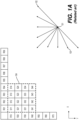
- FIG. 1A depicted in the lower right is a subset of nine predictor directions known from H.265's 33 possible predictor directions (corresponding to the 33 angular modes of the 35 intra modes).
- the point where the arrows converge (101) represents the sample being predicted.
- the arrows represent the direction from which the sample is being predicted.
- arrow (102) indicates that sample (101) is predicted from a sample or samples to the upper right, at a 45 degree angle from the horizontal.
- arrow (103) indicates that sample (101) is predicted from a sample or samples to the lower left of sample (101), in a 22.5 degree angle from the horizontal.
- a square block (104) of 4x4 samples (indicated by a dashed, boldface line).
- the square block (104) includes 16 samples, each labelled with an "S", its position in the Y dimension (e.g., row index) and its position in the X dimension (e.g., column index).
- sample S21 is the second sample in the Y dimension (from the top) and the first (from the left) sample in the X dimension.
- sample S44 is the fourth sample in block (104) in both the Y and X dimensions.
- S44 is at the bottom right. Further shown are reference samples that follow a similar numbering scheme.
- a reference sample is labelled with an R, its Y position (e.g., row index) and X position (column index) relative to block (104).
- R its Y position (e.g., row index) and X position (column index) relative to block (104).
- Y position e.g., row index
- X position column index
- Intra picture prediction can work by copying reference sample values from the neighboring samples as appropriated by the signaled prediction direction. For example, assume the coded video bitstream includes signaling that, for this block, indicates a prediction direction consistent with arrow (102)-that is, samples are predicted from a prediction sample or samples to the upper right, at a 45 degree angle from the horizontal. In that case, samples S41, S32, S23, and S14 are predicted from the same reference sample R05. Sample S44 is then predicted from reference sample R08.
- the values of multiple reference samples may be combined, for example through interpolation, in order to calculate a reference sample; especially when the directions are not evenly divisible by 45 degrees.
- FIG. 1B shows a schematic (180) that depicts 65 intra prediction directions according to JEM to illustrate the increasing number of prediction directions over time.
- the mapping of intra prediction directions bits in the coded video bitstream that represent the direction can be different from video coding technology to video coding technology; and can range, for example, from simple direct mappings of prediction direction to intra prediction mode, to codewords, to complex adaptive schemes involving most probable modes, and similar techniques. In all cases, however, there can be certain directions that are statistically less likely to occur in video content than certain other directions. As the goal of video compression is the reduction of redundancy, those less likely directions will, in a well working video coding technology, be represented by a larger number of bits than more likely directions.
- Motion compensation can be a lossy compression technique and can relate to techniques where a block of sample data from a previously reconstructed picture or part thereof (reference picture), after being spatially shifted in a direction indicated by a motion vector (MV henceforth), is used for the prediction of a newly reconstructed picture or picture part.
- the reference picture can be the same as the picture currently under reconstruction.
- MVs can have two dimensions X and Y, or three dimensions, the third being an indication of the reference picture in use (the latter, indirectly, can be a time dimension).
- an MV applicable to a certain area of sample data can be predicted from other MVs, for example from those related to another area of sample data spatially adjacent to the area under reconstruction, and preceding that MV in decoding order. Doing so can substantially reduce the amount of data required for coding the MV, thereby removing redundancy and increasing compression.
- MV prediction can work effectively, for example, because when coding an input video signal derived from a camera (known as natural video) there is a statistical likelihood that areas larger than the area to which a single MV is applicable move in a similar direction and, therefore, can in some cases be predicted using a similar motion vector derived from MVs of neighboring area.
- MV prediction can be an example of lossless compression of a signal (namely: the MVs) derived from the original signal (namely: the sample stream).
- MV prediction itself can be lossy, for example because of rounding errors when calculating a predictor from several surrounding MVs.
- a current block (201) comprises samples that have been found by the encoder during the motion search process to be predictable from a previous block of the same size that has been spatially shifted.
- the MV can be derived from metadata associated with one or more reference pictures, for example from the most recent (in decoding order) reference picture, using the MV associated with either one of five surrounding samples, denoted A0, A1, and B0, B 1, B2 (202 through 206, respectively).
- the MV prediction can use predictors from the same reference picture that the neighboring block is using.
- an apparatus for video decoding includes processing circuitry. For example, the processing circuitry determines a first combination from reconstructed samples of a first color component within a filter support region. Then, the processing circuitry determines, based on a mapping that associates offset values with combinations of possible reconstructed sample values, a first offset value that is associated with the first combination, and applies the first offset value on a to-be filtered sample of a second color component in the filter support region to determine a filtered sample of the second color component.
- the mapping is a non linear mapping defined in a form of a lookup table.
- the second color component is one of the first color component or a different color component from the first color component.
- the processing circuitry uses at least one of a linear operation and a quantization operation to determine the first combination from the reconstructed samples of the first color component within the filter support region. In some examples, the processing circuitry calculates differences of the reconstructed samples of the first color component, and quantizes the differences to determine the first combination. In an example, the processing circuitry calculates differences of surrounding reconstructed samples to a collocated sample within the reconstructed samples of the first color component. The collocated sample is located at a same position as the to-be filtered sample of the second color component. Then, the processing circuitry quantizes the differences based on a quantization step size to determine the first combination.
- the mapping associates the offset values with the combinations of a complete domain for the reconstructed samples of the first color component within the filter support region. In another embodiment, the mapping associates the offset values with the combinations of a subset domain for the reconstructed samples of the first color component within the filter support region.
- the mapping is carried in at least one of a video parameter set (VPS), a sequence parameter set (SPS), a picture parameter set (PPS), an adaptation parameter set (APS), a slice header, and a tile header of a coded video bitstream.
- VPS video parameter set
- SPS sequence parameter set
- PPS picture parameter set
- APS adaptation parameter set
- slice header a tile header of a coded video bitstream.
- the processing circuitry derives the offset values of the mapping based on cost measures, and includes the mapping in at least one of a video parameter set (VPS), a sequence parameter set (SPS), a picture parameter set (PPS), an adaptation parameter set (APS), a slice header, and a tile header of a coded video bitstream.
- VPS video parameter set
- SPS sequence parameter set
- PPS picture parameter set
- APS adaptation parameter set
- slice header a tile header of a coded video bitstream.
- the processing circuitry adds the first offset value with the to-be filtered sample of the second color component to determine an intermediate filtered sample, and clips the intermediate filtered sample based on a maximum value and a minimum value to determine the filtered sample of the second color component.
- aspects of the disclosure also provide a non-transitory computer-readable medium storing instructions which when executed by a computer for video decoding cause the computer to perform any of the methods for video decoding.
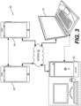
- FIG. 3 illustrates a simplified block diagram of a communication system (300) according to an embodiment of the present disclosure.
- the communication system (300) includes a plurality of terminal devices that can communicate with each other, via, for example, a network (350).
- the communication system (300) includes a first pair of terminal devices (310) and (320) interconnected via the network (350).
- the first pair of terminal devices (310) and (320) performs unidirectional transmission of data.
- the terminal device (310) may code video data (e.g., a stream of video pictures that are captured by the terminal device (310)) for transmission to the other terminal device (320) via the network (350).
- the encoded video data can be transmitted in the form of one or more coded video bitstreams.
- the terminal device (320) may receive the coded video data from the network (350), decode the coded video data to recover the video pictures and display video pictures according to the recovered video data.
- Unidirectional data transmission may be common in media serving applications and the like.
- the communication system (300) includes a second pair of terminal devices (330) and (340) that performs bidirectional transmission of coded video data that may occur, for example, during videoconferencing.
- each terminal device of the terminal devices (330) and (340) may code video data (e.g., a stream of video pictures that are captured by the terminal device) for transmission to the other terminal device of the terminal devices (330) and (340) via the network (350).
- Each terminal device of the terminal devices (330) and (340) also may receive the coded video data transmitted by the other terminal device of the terminal devices (330) and (340), and may decode the coded video data to recover the video pictures and may display video pictures at an accessible display device according to the recovered video data.
- the terminal devices (310), (320), (330) and (340) may be illustrated as servers, personal computers and smart phones but the principles of the present disclosure may be not so limited. Embodiments of the present disclosure find application with laptop computers, tablet computers, media players and/or dedicated video conferencing equipment.
- the network (350) represents any number of networks that convey coded video data among the terminal devices (310), (320), (330) and (340), including for example wireline (wired) and/or wireless communication networks.
- the communication network (350) may exchange data in circuit-switched and/or packet-switched channels.
- Representative networks include telecommunications networks, local area networks, wide area networks and/or the Internet. For the purposes of the present discussion, the architecture and topology of the network (350) may be immaterial to the operation of the present disclosure unless explained herein below.
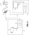
- FIG. 4 illustrates, as an example for an application for the disclosed subject matter, the placement of a video encoder and a video decoder in a streaming environment.
- the disclosed subject matter can be equally applicable to other video enabled applications, including, for example, video conferencing, digital TV, storing of compressed video on digital media including CD, DVD, memory stick and the like, and so on.
- a streaming system may include a capture subsystem (413), that can include a video source (401), for example a digital camera, creating for example a stream of video pictures (402) that are uncompressed.
- the stream of video pictures (402) includes samples that are taken by the digital camera.
- the stream of video pictures (402), depicted as a bold line to emphasize a high data volume when compared to encoded video data (404) (or coded video bitstreams), can be processed by an electronic device (420) that includes a video encoder (403) coupled to the video source (401).
- the video encoder (403) can include hardware, software, or a combination thereof to enable or implement aspects of the disclosed subject matter as described in more detail below.
- the encoded video data (404) (or encoded video bitstream (404)), depicted as a thin line to emphasize the lower data volume when compared to the stream of video pictures (402), can be stored on a streaming server (405) for future use.
- One or more streaming client subsystems such as client subsystems (406) and (408) in FIG. 4 can access the streaming server (405) to retrieve copies (407) and (409) of the encoded video data (404).
- a client subsystem (406) can include a video decoder (410), for example, in an electronic device (430).
- the video decoder (410) decodes the incoming copy (407) of the encoded video data and creates an outgoing stream of video pictures (411) that can be rendered on a display (412) (e.g., display screen) or other rendering device (not depicted).
- the encoded video data (404), (407), and (409) e.g., video bitstreams
- video coding/compression standards examples include ITU-T Recommendation H.265.
- a video coding standard under development is informally known as Versatile Video Coding (WC).
- WC Versatile Video Coding
- the electronic devices (420) and (430) can include other components (not shown).
- the electronic device (420) can include a video decoder (not shown) and the electronic device (430) can include a video encoder (not shown) as well.
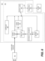
- FIG. 5 shows a block diagram of a video decoder (510) according to an embodiment of the present disclosure.
- the video decoder (510) can be included in an electronic device (530).
- the electronic device (530) can include a receiver (531) (e.g., receiving circuitry).
- the video decoder (510) can be used in the place of the video decoder (410) in the FIG. 4 example.
- the receiver (531) may receive one or more coded video sequences to be decoded by the video decoder (510); in the same or another embodiment, one coded video sequence at a time, where the decoding of each coded video sequence is independent from other coded video sequences.
- the coded video sequence may be received from a channel (501), which may be a hardware/software link to a storage device which stores the encoded video data.
- the receiver (531) may receive the encoded video data with other data, for example, coded audio data and/or ancillary data streams, that may be forwarded to their respective using entities (not depicted).
- the receiver (531) may separate the coded video sequence from the other data.
- a buffer memory (515) may be coupled in between the receiver (531) and an entropy decoder / parser (520) ("parser (520)" henceforth).
- the buffer memory (515) is part of the video decoder (510). In others, it can be outside of the video decoder (510) (not depicted). In still others, there can be a buffer memory (not depicted) outside of the video decoder (510), for example to combat network jitter, and in addition another buffer memory (515) inside the video decoder (510), for example to handle playout timing.
- the row (1851) is co-located with the next row (1812).
- the above descriptions can be suitably adapted to the rows (1852)-(1854), and the detailed descriptions are omitted for purposes of brevity.
- chroma subsampling format is 4:2:0 (e.g., chroma_format_idc is equal to 1).
- a variable chroma location type indicates the current rows (e.g., ChromaLocType is chroma_sample_loc_type_top_field) or the next rows (e.g., ChromaLocType is chroma_sample_loc_type_bottom_field).
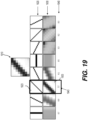
- FIG. 19 shows an example of direction search according to an embodiment of the disclosure.
- a block (1910) is an 8 ⁇ 8 block that is reconstructed, and output from a deblocking filter.
- the direction search can determine a direction from 8 directions shown by (1920) for the block (1910).
- 8 perfectly directional blocks (1930) are formed respectively corresponding to the 8 directions (1920).
- a perfectly directional block corresponding to a direction is a block where pixels along a line of the direction have the same value.
- a difference measure, such as SSD, RMS error and the like, of the block (1910) and each of the perfectly directional blocks (1930) can be calculated.
- the RMS errors are shown by (1940). As shown by (1943), the RMS error of the block (1910) and the perfectly directional block (1933) is the smallest, thus the direction (1923) is the direction that best matches the pattern in the block (1910).
- a non-linear low pass directional filter can be determined.
- the filter taps of the non-linear low pass directional filter can be aligned along the identified direction to reduce ringing while preserving the directional edges or patterns.
- directional filtering alone sometimes cannot sufficiently reduce ringing.
- extra filter taps are also used on pixels that do not lie along the identified direction. To reduce the risk of blurring, the extra filter taps are treated more conservatively. For this reason, CDEF includes primary filter taps and secondary filter taps.
- the function f(d, S, D) is equal to D, that can make the filter to behave like a linear filter; when the difference is large, the function f(d, S, D) is equal to 0, that can effectively ignores the filter taps.
- in-loop restoration schemes are used in video coding post deblocking to generally denoise and enhance the quality of edges, beyond the deblocking operation.
- the in-loop restoration schemes are switchable within a frame per suitably sized tile.
- the in-loop restoration schemes are based on separable symmetric Wiener filters, dual self-guided filters with subspace projection, and domain transform recursive filters. Because content statistics can vary substantially within a frame, in-loop restoration schemes are integrated within a switchable framework where different schemes can be triggered in different regions of the frame.
- Separable symmetric Wiener filter can be one of the in-loop restoration schemes.
- F is constrained to be separable so that the filtering can be implemented as separable horizontal and vertical w-tap convolutions.
- each of the horizontal and vertical filters are constrained to be symmetric.
- the sum of both the horizontal and vertical filter coefficients is assumed to sum to 1.
- the specific form of self-guided filter is controlled by r and e, where a higher r implies a higher spatial variance and a higher e implies a higher range variance.
- FIG. 20 shows an example illustrating subspace projection in some examples. As shown in FIG. 20 , even though none of the restorations X 1 , X 2 are close to the source Y, appropriate multipliers ⁇ , ⁇ can bring them much closer to the source Y as long as they are moving somewhat in the right direction.
- SAO sample adaptive offset
- SAO is applied to the reconstruction signal after a deblocking filter.
- SAO can use the offset values given in the slice header.
- the encoder can decide whether to apply (enable) SAO on a slice. When SAO is enabled, the current picture allows recursive splitting of a coding unit into four sub-regions and each sub-region can select an SAO type from multiple SAO types based on features in the sub-region.
- FIG. 21 shows a table (2100) of a plurality of SAO types according to an embodiment of the disclosure.
- SAO types 0-6 are shown. It is noted that SAO type 0 is used to indicate no SAO application. Further, each SAO type of SAO type 1 to SAO type 6 includes multiple categories. SAO can classify reconstructed pixels of a sub-region into categories and reduce the distortion by adding an offset to pixels of each category in the sub-region. In some examples, edge properties can be used for pixel classification in SAO types 1-4, and pixel intensity can be used for pixel classification in SAO types 5-6.
- band offset can be used to classify all pixels of a sub-region into multiple bands.
- Each band of the multiple bands includes pixels in the same intensity interval.
- the intensity range is equally divided into a plurality of intervals, such as 32 intervals from zero to the maximum intensity value (e.g. 255 for 8-bit pixels), and each interval is associated with an offset.
- the 32 bands are divided into two groups, such as a first group and a second group.
- the first group includes the central 16 bands (e.g., 16 intervals that are in the middle of the intensity range), while the second group includes of the rest 16 bands (e.g., 8 intervals that are at the low side of the intensity range and 8 intervals that are at the high side of the intensity range).
- the rest 16 bands e.g., 8 intervals that are at the low side of the intensity range and 8 intervals that are at the high side of the intensity range.
- only offsets of one of the two groups are transmitted.
- the five most significant bits of each pixel can be directly used as the band index.
- edge offset can be used for pixel classification and determination of offsets.
- pixel classification can be determined based on 1-dimensional 3-pixel patterns with consideration of edge directional information.
- FIG. 22 shows examples of 3-pixel patterns for pixel classification in edge offset in some examples.
- a first pattern (2210) (as shown by 3 grey pixels) is referred to as 0-degree pattern (horizontal direction is associated with the 0-degree pattern)
- a second pattern (2220) (as shown by 3 grey pixels) is referred to as 90-degree pattern (vertical direction is associated with the 90-degree pattern)
- a third pattern (2230) (as shown by 3 grey pixels) is referred to as 135-degree pattern (135 degree diagonal direction is associated with the 135-degree pattern)
- a fourth pattern (2240) (as shown by 3 grey pixels) is referred to as 45-degree pattern (45 degree diagonal direction is associated with the 45-degree pattern).
- one of the four directional patterns shown in FIG. 22 can be selected considering edge directional information for a sub-region.
- the selection can be sent in the coded video bitstream as side information in an example.
- pixels in the sub-region can be classified into multiple categories by comparing each pixel with its two neighboring pixels on the direction associated with the directional pattern.
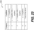
- FIG. 23 shows a table (2300) for pixel classification rule for edge offset in some examples. Specifically, a pixel c (also shown in each pattern of FIG. 22 ) is compared with two neighboring pixels (also shown by grey color in each pattern of FIG. 22 ), and the pixel c can be classified into one of category 0-4 based on the comparison according to the pixel classification rule shown in FIG. 23 .
- the SAO on the decoder side can be operated independently of largest coding unit (LCU) (e.g., CTU), so that the line buffers can be saved.
- LCU largest coding unit
- pixels of the top and bottom rows in each LCU are not SAO processed when the 90-degree, 135-degree, and 45-degree classification patterns are chosen; pixels of the leftmost and rightmost columns in each LCU are not SAO processed when the 0-degree, 135-degree, and 45-degree patterns are chosen.
- FIG. 24 shows an example (2400) of syntaxes that may need to be signaled for a CTU if the parameters are not merged from neighboring CTU.
- a syntax element sao_type_idx[ cldx ][ rx ][ ry ] can be signaled to indicate the SAO type of a sub-region.
- the SAO type may be BO (band offset) or EO (edge offset).
- each of the BO and EO types has four SAO offset values (sao_offset[cIdx][rx][ry][0] to sao_offset[cldx][rx][ry][3]) that are signaled.
- SAO is a filtering process that requires extra signaling overheads to indicate all related information that is required to perform SAO filtering, as shown in FIG. 24 , which may limit the potential of SAO.
- a filtering process can use the reconstructed samples of a first color component as input (e.g., Y or Cb or Cr, or R or G or B) to generate an output, and the output of the filtering process is applied on a second color component that can be the same one as the first color component or that can be another color component that is different from the first color component.
- a first color component e.g., Y or Cb or Cr, or R or G or B
- the output of the filtering process is applied on a second color component that can be the same one as the first color component or that can be another color component that is different from the first color component.
- filter coefficients are derived based on some mathematical equations.
- the derived filter coefficients are signaled from encoder side to the decoder side, and the derived filter coefficients are used to generate offsets using linear combinations.
- the generated offsets are then added to reconstructed samples as a filtering process.
- the offsets are generated based on linear combinations of the filtering coefficients with luma samples, and the generated offsets are added to the reconstructed chroma samples.
- the related example of CCF is based on an assumption of a linear mapping relationship between the reconstructed luma sample values and the delta values between the original and reconstructed chroma samples.
- the mapping between the reconstructed luma sample values and the delta values between the original and reconstructed chroma samples does not necessarily follow a linear mapping process, thus the coding performance of CCF may be limited under the linear mapping relationship assumption.
- non linear mapping techniques that can be used in cross-component filtering and/or same color component filtering without significant signaling overheads.
- the non linear mapping techniques can be used in the cross-component filtering to generate cross-component sample offset.
- the non linear mapping techniques can be used in the same color component filtering to generate local sample offset.
- SO-NLM sample offset by non linear mapping
- CCSO cross-component sample offset
- LSO local sample offset
- CCSO and LSO can be used as loop filtering to reduce distortion of reconstructed samples.
- CCSO and LSO do not rely on the linear mapping assumption used in the related example CCF.
- CCSO does not rely on the assumption of linear mapping relationship between the luma reconstructed sample values and the delta values between the original chroma samples and chroma reconstructed samples.
- LSO does not rely on the assumption of linear mapping relationship between the reconstructed sample values of a color component and the delta values between the original samples of the color component and reconstructed samples of the color component.
- SO-NLM filtering process uses the reconstructed samples of a first color component as input (e.g., Y or Cb or Cr, or R or G or B) to generate an output, and the output of the filtering process is applied on a second color component.
- a first color component e.g., Y or Cb or Cr, or R or G or B
- the output of the filtering process is applied on a second color component.
- the description is applicable for LSO
- the description is applicable for CCSO.
- a non linear mapping is derived at encoder side.
- a non linear mapping is between reconstructed samples of a first color component in the filter support region and offsets to be added to a second color component in the filter support region.
- the non linear mapping is used in LSO; when the second color component is different from the first color component, the non linear mapping is used in CCSO.
- the domain of the non linear mapping is determined by different combinations of processed input reconstructed samples (also referred to as combinations of possible reconstructed sample values).
- reconstructed samples from a first color component located in a filter support area are determined.
- the filter support area is an area within which the filter can be applied, and the filter support area can have any suitable shape.
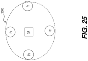
- FIG. 25 shows an example of a filter support area (2500) according to some embodiments of the disclosure.
- the filter support area (2500) includes four reconstructed samples: P0, P1, P2 and P3 of a first color component.
- the four reconstructed samples can form a cross-shape in the vertical direction and the horizontal direction, and the center location of the cross-shape is the location for the sample to be filtered.
- a sample at the center location and of the same color component as P0-P3 is denoted by C.
- a sample at the center location and of a second color component is denoted by F.
- the second color component can be the same as the first color component of P0-P3 or can be different from the first color component of P0-P3.
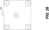
- FIG. 26 shows an example of another filter support area (2600) according to some embodiments of the disclosure.
- the filter support area (2600) includes four reconstructed samples P0, P1, P2 and P3 of a first color component that form a square shape.
- the center location of the square shape is the location of the sample to be filtered.
- a sample at the center location and of the same color component as P0-P3 is denoted by C.
- a sample at the center location and of a second color component is denoted by F.
- the second color component can be the same as the first color component of P0-P3 or can be different from the first color component of P0-P3.
- the reconstructed samples are suitably processed to form filter taps.
- the reconstructed samples are processed in following two steps.
- the delta values respectively between P0-P3 and C are computed.
- m0 denotes the delta value between P0 to C
- m1 denotes the delta value between P1 to C
- m2 denotes the delta value between P2 to C
- m3 denotes the delta value between P3 to C.
- the delta values m0-m3 are further quantized, the quantized values are denoted as d0, d1, d2, d3.
- the quantized value can be one of -1, 0, 1 based on a quantization process.
- a value m can be quantized to -1 when m is smaller than -N (N is a positive value and is referred to as quantization step size); the value m can be quantized to 0 when m is in a range of [-N, N]; and the value m can be quantized to 1 when m is greater than N.
- the quantization step size N can be one of 4, 8, 12, 16 and the like.
- the quantized values d0-d3 are filter taps and can be used to identify one combination in the filter domain.
- the filter taps d0-d3 can form a combination in the filter domain.
- Each filter tap can have three quantized values, thus when four filter taps are used, the filter domain includes 81 (3 ⁇ 3 ⁇ 3 ⁇ 3) combinations.
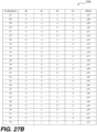
- FIGs. 27A-27C show a table (2700) having 81 combinations according to an embodiment of the disclosure.
- the table (2700) includes 81 rows corresponding to 81 combinations.
- the first column includes an index of the combinations;
- the second column includes the value of filter tap d0 for the combination;
- the third column includes the value of filter tap d1 for the combination;
- the fourth column includes the value of filter tap d2 for the combination;
- the fifth column includes the value of filter tap d3 for the combination;
- the six column includes the offset value associated with the combination for the non linear mapping.
- the offset value (denoted by s) associated with the combination of d0-d3 can be determined according to the table (2700).
- offset values s0-s80 are integers, such as 0, 1, -1, 3, -3, 5, -5, -7, and the like.
- the second color component in the above description is the same as the first color component; and, in the case of CCSO, the second color component in the above description can be different from the first color component.
- the encoding device can derive a mapping between reconstructed samples of a first color component in a filter support region and the offsets to be added to reconstructed samples of a second color component.
- the mapping can be any suitable linear or non-linear mapping.
- the filtering process can be applied at the encoder side and/or the decoder side based on the mapping.
- the mapping is suitably informed to the decoder (e.g., the mapping is included in a coded video bitstream that is transmitted from the encoder side to the decoder side), and then the decoder can perform the filtering process based on the mapping.
- the mapping is a non linear mapping between reconstructed samples of a first color component and offset to be applied to reconstructed samples of a second color component.
- the reconstructed samples of the first color component in the filter support region can be input to the filtering process, and the offset is the output of the filtering process.
- the offset can be applied to a reconstructed sample of the second color component in the filter support region.
- a lookup table is used to describe the mapping.
- the lookup table can associate the input of the filtering process (reconstructed samples of the first color component) with output of the filtering process (offsets to be applied to reconstructed samples of the second color component).
- the corresponding output offset value can be retrieved from the lookup table.
- the input is reconstructed luma samples located in a given filter support area (region), and the output is offset to be applied on chroma reconstructed sample.
- the reconstructed samples are first quantized before being used as the input of the filtering process.
- the reconstructed samples can be quantized based on quantization steps.
- the reconstructed samples are processed using linear operations and then used as the input of the filtering process. For example, subtractions of the reconstructed samples to a value (e.g., a center reconstructed sample, an average of the reconstructed samples) can be performed. The results of the subtractions can be used as the input of the filtering process.
- a value e.g., a center reconstructed sample, an average of the reconstructed samples
- the reconstructed samples are first processed using linear operations and the output of linear operations are further quantized and then used as the input of the filtering process.
- the first step uses the linear operations to calculate the delta values m0-m3 respectively between P0-P3 and C. Then, in the second step, the delta values m0-m3 are further quantized to d0-d3.
- the domain of the mapping is determined by different combinations of processed (e.g., linear processing) input reconstructed samples, such as combinations of P0-P3, combinations of m0-m3, combinations of d0-d3.
- all possible combinations of processed input reconstructed samples are included in the domain (referred to as a complete domain).
- a combination of processed reconstructed samples is identified by the quantized differences between the surrounding samples to the center sample, such as a combination of d0-d3.
- a combination of processed reconstructed samples is identified by the quantized differences between the surrounding samples.
- n0 is a difference between P0 and P1
- n1 is a different between P1 and P2
- n2 is a difference between P2 and P3
- n3 is a different between P3 and P0.
- n0-n3 can be quantized similarly to m0-m3 to determine e0-e3 that can be used as a combination of processed reconstructed samples.
- the difference m0-m3 of surrounding samples P0-P3 to the center sample C can be quantized into [-1, 0, 1], based on a quantization step size N (N is a positive integer, such as 1, 3, 5, 7).
- N is a positive integer, such as 1, 3, 5, 7.
- N is a positive integer, such as 1, 3, 5, 7.
- to quantize a value when the value is smaller than -N, the value is quantized to be -1; when the value is in the range of [-N, N], the value is quantized to be 0; and when the value is larger than N, the value is quantized to be 1.
- the total number of combinations is 81 (3 4 ), such as the table (2700) shown in FIGs. 27A-27C .
- the combinations of processed reconstructed samples depend on the internal bit depth that the codec is operating.
- the calculations of m0-m3 depend on the internal bit depth, and m0-m3 are quantized to determine d0-d3.
- the combinations of d0-d3 can depend on the internal bit depth.
- the combinations of processed reconstructed samples depend on the quantization parameters, such as the quantization step size.
- the determination of d0-d3 in the second step of the specific example is based on the quantization step size N.
- any suitable reconstructed samples in the filter support region can be used to determine the combination.
- reconstructed samples located at the boundary of the filter support region are referred to as surrounding samples and can be used to determine the combination.
- reconstructed samples in the filter support area excluding the center position are referred to as surrounding samples, and can be used to determine the combination.
- reconstructed samples in the filter support area excluding the samples close to the center position are referred to as surrounding samples, and can be sued to determine the combination.
- the domain of the mapping is determined by different combinations of processed (e.g., linear processing) reconstructed samples (e.g., d0-d3).
- processed reconstructed samples e.g., d0-d3
- a pre-defined subset of combinations of processed reconstructed samples e.g., d0-d3 is included in the domain (referred to as a subset domain).
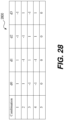
- FIG. 28 shows a lookup table (2800) according to an embodiment of the disclosure.
- the domain of the mapping in the lookup table (2800) includes a subset of all combinations of d0-d3, such as 5 combinations in FIG. 28 .
- the offsets output from the filtering process are integers within a predefined range [P, Q].
- P and Q can be integers.
- An example of the range is [-K, K - 1], where K is a positive integer.
- Example values of K include but not limited to 16, 8, 4, 2, 1.
- the values of P and Q depend on the internal bit depth that the codec is operating. In another embodiment, the values of P and Q depend on the quantization parameters, such as the quantization step size N. In another embodiment, the offsets output from the filtering process are a predefined subset of integers. For example, the predefined subset of integers includes integers with values -2 T and/or 2 T (where T is integers), such as 16, -16, 8, -8, 4, -4, 2, -2, 1, and the like.
- an offset associated with a combination of processed reconstructed samples in the mapping can be determined by the encoder based on pre-defined cost measures.
- the cost measure is defined as average of difference between original value and reconstructed sample values of to-be-filtered samples in the second color component.
- the reconstructed samples for inputting to the filtering process are from a first color component, and the to-be-filtered samples are from a second color component that is different from the first color component.
- the reconstructed samples for inputting to the filtering process are from a first color component, and the to-be-filtered samples are from a second color component that is the same color component as the first color component.
- the mapping information can be signaled from the encoder side to the decoder side.
- the mapping information is carried in the coded video bitstream, such as in video parameter set (VPS), in sequence parameter set (SPS), in picture parameter set (PPS), in adaptation parameter set (APS), in slice header, in tile header and the like.
- the filtering process determines the offset value based on the mapping and a combination determined based on reconstructed samples of the first color component. For example, the offset value is associated with the combination in the mapping (e.g., lookup table). Then, the offset value is applied to the to-be-filtered sample in the second color component.
- clipping is performed after adding the offset value to the to-be-filtered sample to ensure the filtered sample value does not exceed maximum or minimum values. In an example, clipping is performed according to Eq.
- clip x max min x , max _ val , min _ val
- max_val denotes maximum sample value
- min_val denotes minimum sample values
- x is the sample value to be clipped.
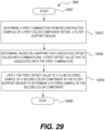
- FIG. 29 shows a flow chart outlining a process (2900) according to an embodiment of the disclosure.
- the process (2900) can be used to reconstruct a block in a picture of a coded video sequence.
- the term block may be interpreted as a prediction block, a coding unit, a luma block, a chroma block, or the like.
- the process (2900) are executed by processing circuitry, such as the processing circuitry in the terminal devices (310), (320), (330) and (340), the processing circuitry that performs functions of the video encoder (403), the processing circuitry that performs functions of the video decoder (410), the processing circuitry that performs functions of the video decoder (510), the processing circuitry that performs functions of the video encoder (603), and the like.
- the process (2900) is implemented in software instructions, thus when the processing circuitry executes the software instructions, the processing circuitry performs the process (2900). The process starts at (S2901) and proceeds to (S2910).
- a first combination is determined from reconstructed samples of a first color component within a filter support region.
- at least one of a linear operation and a quantization operation can be used to determine the first combination from the reconstructed samples of the first color component within the filter support region.
- differences of the reconstructed samples of the first color component can be calculated. Then, the differences are quantized to determine the first combination. In some examples, differences of surrounding reconstructed samples of the reconstructed samples to a collocated sample within the reconstructed samples of the first color component are calculated. The collocated sample is located at a same position as the to-be filtered sample of the second color component. Then, the differences are quantized based on a quantization step size to determine the first combination. It is noted that the first combination can depend on internal bit depth and quantization parameter, such as quantization step size and the like.
- the surrounding reconstructed samples are located at the boundary of the filter support region.
- the surrounding reconstructed samples are samples in the filter support region excluding the sample at the center position of the filter support region.
- the surrounding reconstructed samples are samples in the filter support region excluding the samples located close to the center position of the filter support region.
- a first offset value associated with the first combination is determined based on a mapping that associates offset values with combinations.
- the mapping is a non linear mapping defined in a form of a lookup table.
- the mapping associates the offset values with the combinations of a complete domain for the reconstructed samples of the first color component within the filter support region.
- the complete domain of mapping includes all possible combinations. For example, when four reconstructed samples are each processed and quantized to one of three values, the number of all possible combinations is 81 (3 4 ).
- the mapping associates the offset values with the combinations of a subset domain for the reconstructed samples of the first color component within the filter support region.
- the subset domain includes a subset of combinations of the complete domain.
- the mapping is carried in at least one of a video parameter set (VPS), a sequence parameter set (SPS), a picture parameter set (PPS), an adaptation parameter set (APS), a slice header, and a tile header of a coded video bitstream.
- VPS video parameter set
- SPS sequence parameter set
- PPS picture parameter set
- APS adaptation parameter set
- slice header a tile header of a coded video bitstream.
- the offset values of the mapping are derived based on cost measures.
- the mapping can be included in at least one of a video parameter set (VPS), a sequence parameter set (SPS), a picture parameter set (PPS), an adaptation parameter set (APS), a slice header, and a tile header of a coded video bitstream.
- VPS video parameter set
- SPS sequence parameter set
- PPS picture parameter set
- APS adaptation parameter set
- slice header a tile header of a coded video bitstream.
- the first offset value is applied onto a to-be filtered sample of a second color component in the filter support region to determine a filtered sample of the second color component.
- the second color component is the first color component.
- the second color component is a different color component from the first color component.
- the first color component is luma component
- the second color component is chroma component.
- the first offset value is added with the to-be filtered sample of the second color component to determine an intermediate filtered sample. Then, the intermediate filtered sample is clipped based on a maximum value and a minimum value to determine the filtered sample of the second color component.
- the process (2900) proceeds to (S2999), and terminates.
- the process (2900) can be suitably adapted. Step(s) in the process (2900) can be modified and/or omitted. Additional step(s) can be added. Any suitable order of implementation can be used.
- Embodiments in the disclosure may be used separately or combined in any order. Further, each of the methods (or embodiments), an encoder, and a decoder may be implemented by processing circuitry (e.g., one or more processors or one or more integrated circuits). In one example, the one or more processors execute a program that is stored in a non-transitory computer-readable medium.
- processing circuitry e.g., one or more processors or one or more integrated circuits.
- the one or more processors execute a program that is stored in a non-transitory computer-readable medium.
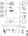
- FIG. 30 shows a computer system (3000) suitable for implementing certain embodiments of the disclosed subject matter.
- the computer software can be coded using any suitable machine code or computer language, that may be subject to assembly, compilation, linking, or like mechanisms to create code comprising instructions that can be executed directly, or through interpretation, micro-code execution, and the like, by one or more computer central processing units (CPUs), Graphics Processing Units (GPUs), and the like.
- CPUs computer central processing units
- GPUs Graphics Processing Units
- the instructions can be executed on various types of computers or components thereof, including, for example, personal computers, tablet computers, servers, smartphones, gaming devices, internet of things devices, and the like.
- FIG. 30 for computer system (3000) are exemplary in nature and are not intended to suggest any limitation as to the scope of use or functionality of the computer software implementing embodiments of the present disclosure. Neither should the configuration of components be interpreted as having any dependency or requirement relating to any one or combination of components illustrated in the exemplary embodiment of a computer system (3000).
- Computer system (3000) may include certain human interface input devices.
- a human interface input device may be responsive to input by one or more human users through, for example, tactile input (such as: keystrokes, swipes, data glove movements), audio input (such as: voice, clapping), visual input (such as: gestures), olfactory input (not depicted).
- the human interface devices can also be used to capture certain media not necessarily directly related to conscious input by a human, such as audio (such as: speech, music, ambient sound), images (such as: scanned images, photographic images obtain from a still image camera), video (such as two-dimensional video, three-dimensional video including stereoscopic video).
- Input human interface devices may include one or more of (only one of each depicted): keyboard (3001), mouse (3002), trackpad (3003), touch screen (3010), data-glove (not shown), joystick (3005), microphone (3006), scanner (3007), camera (3008).
- Computer system (3000) may also include certain human interface output devices.
- Such human interface output devices may be stimulating the senses of one or more human users through, for example, tactile output, sound, light, and smell/taste.
- Such human interface output devices may include tactile output devices (for example tactile feedback by the touch-screen (3010), data-glove (not shown), or joystick (3005), but there can also be tactile feedback devices that do not serve as input devices), audio output devices (such as: speakers (3009), headphones (not depicted)), visual output devices (such as screens (3010) to include CRT screens, LCD screens, plasma screens, OLED screens, each with or without touch-screen input capability, each with or without tactile feedback capability-some of which may be capable to output two dimensional visual output or more than three dimensional output through means such as stereographic output; virtual-reality glasses (not depicted), holographic displays and smoke tanks (not depicted)), and printers (not depicted).
- Computer system (3000) can also include human accessible storage devices and their associated media such as optical media including CD/DVD ROM/RW (3020) with CD/DVD or the like media (3021), thumb-drive (3022), removable hard drive or solid state drive (3023), legacy magnetic media such as tape and floppy disc (not depicted), specialized ROM/ASIC/PLD based devices such as security dongles (not depicted), and the like.
- optical media including CD/DVD ROM/RW (3020) with CD/DVD or the like media (3021), thumb-drive (3022), removable hard drive or solid state drive (3023), legacy magnetic media such as tape and floppy disc (not depicted), specialized ROM/ASIC/PLD based devices such as security dongles (not depicted), and the like.
- Computer system (3000) can also include an interface (3054) to one or more communication networks (3055).
- Networks can for example be wireless, wireline, optical.
- Networks can further be local, wide-area, metropolitan, vehicular and industrial, real-time, delay-tolerant, and so on.
- Examples of networks include local area networks such as Ethernet, wireless LANs, cellular networks to include GSM, 3G, 4G, 5G, LTE and the like, TV wireline or wireless wide area digital networks to include cable TV, satellite TV, and terrestrial broadcast TV, vehicular and industrial to include CANBus, and so forth.
- Certain networks commonly require external network interface adapters that attached to certain general purpose data ports or peripheral buses (3049) (such as, for example USB ports of the computer system (3000)); others are commonly integrated into the core of the computer system (3000) by attachment to a system bus as described below (for example Ethernet interface into a PC computer system or cellular network interface into a smartphone computer system).
- computer system (3000) can communicate with other entities.
- Such communication can be uni-directional, receive only (for example, broadcast TV), uni-directional send-only (for example CANbus to certain CANbus devices), or bi-directional, for example to other computer systems using local or wide area digital networks.
- Certain protocols and protocol stacks can be used on each of those networks and network interfaces as described above.
- Aforementioned human interface devices, human-accessible storage devices, and network interfaces can be attached to a core (3040) of the computer system (3000).
- the core (3040) can include one or more Central Processing Units (CPU) (3041), Graphics Processing Units (GPU) (3042), specialized programmable processing units in the form of Field Programmable Gate Areas (FPGA) (3043), hardware accelerators for certain tasks (3044), graphics adapter (3050), and so forth.
- CPU Central Processing Unit
- GPU Graphics Processing Unit
- FPGA Field Programmable Gate Areas
- These devices, along with Read-only memory (ROM) (3045), Random-access memory (3046), internal mass storage such as internal non-user accessible hard drives, SSDs, and the like (3047), may be connected through a system bus (3048).
- the system bus (3048) can be accessible in the form of one or more physical plugs to enable extensions by additional CPUs, GPU, and the like.
- peripheral devices can be attached either directly to the core's system bus (3048), or through a peripheral bus (3049).
- a display (3010) can be connected to the graphics adapter (3050).
- Architectures for a peripheral bus include PCI, USB, and the like.
- CPUs (3041), GPUs (3042), FPGAs (3043), and accelerators (3044) can execute certain instructions that, in combination, can make up the aforementioned computer code. That computer code can be stored in ROM (3045) or RAM (3046). Transitional data can be also be stored in RAM (3046), whereas permanent data can be stored for example, in the internal mass storage (3047). Fast storage and retrieve to any of the memory devices can be enabled through the use of cache memory, that can be closely associated with one or more CPU (3041), GPU (3042), mass storage (3047), ROM (3045), RAM (3046), and the like.
- the computer readable media can have computer code thereon for performing various computer-implemented operations.
- the media and computer code can be those specially designed and constructed for the purposes of the present disclosure, or they can be of the kind well known and available to those having skill in the computer software arts.
- the computer system having architecture (3000), and specifically the core (3040) can provide functionality as a result of processor(s) (including CPUs, GPUs, FPGA, accelerators, and the like) executing software embodied in one or more tangible, computer-readable media.
- processor(s) including CPUs, GPUs, FPGA, accelerators, and the like
- Such computer-readable media can be media associated with user-accessible mass storage as introduced above, as well as certain storage of the core (3040) that are of non-transitory nature, such as core-internal mass storage (3047) or ROM (3045).
- the software implementing various embodiments of the present disclosure can be stored in such devices and executed by core (3040).
- a computer-readable medium can include one or more memory devices or chips, according to particular needs.
- the software can cause the core (3040) and specifically the processors therein (including CPU, GPU, FPGA, and the like) to execute particular processes or particular parts of particular processes described herein, including defining data structures stored in RAM (3046) and modifying such data structures according to the processes defined by the software.
- the computer system can provide functionality as a result of logic hardwired or otherwise embodied in a circuit (for example: accelerator (3044)), which can operate in place of or together with software to execute particular processes or particular parts of particular processes described herein.
- Reference to software can encompass logic, and vice versa, where appropriate.
- Reference to a computer-readable media can encompass a circuit (such as an integrated circuit (IC)) storing software for execution, a circuit embodying logic for execution, or both, where appropriate.
- the present disclosure encompasses any suitable combination of hardware and software.
- the first aspect of the present disclosure relates to a method for filtering in video decoding, comprising: determining, by a processor, a first combination from reconstructed samples of a first color component within a filter support region; determining, by the processor and based on a mapping that associates offset values with combinations of possible reconstructed sample values, a first offset value that is associated with the first combination; and applying, by the processor, the first offset value on a to-be filtered sample of a second color component in the filter support region to determine a filtered sample of the second color component.
- the second aspect of the present disclosure is a method according to the first aspect, wherein the mapping is a non linear mapping defined in a form of a lookup table.
- the third aspect of the present disclosure is a method according to the first aspect, wherein the second color component is one of the first color component, a different color component from the first color component.
- the fourth aspect of the present disclosure is a method according to the first aspect, further comprising: using at least one of a linear operation and a quantization operation to determine the first combination from the reconstructed samples of the first color component within the filter support region.
- the fifth aspect of the present disclosure is a method according to the first aspect, further comprising: calculating differences of the reconstructed samples of the first color component; and quantizing the differences to determine the first combination.
- the sixth aspect of the present disclosure is a method according to the first aspect, further comprising: calculating differences of surrounding reconstructed samples of the reconstructed samples to a collocated sample within the reconstructed samples of the first color component, the collocated sample being located at a same position as the to-be filtered sample of the second color component; and quantizing the differences based on a quantization step size to determine the first combination.
- the seventh aspect of the present disclosure is a method according to the first aspect, wherein the mapping associates the offset values with the combinations of a complete domain for the reconstructed samples of the first color component within the filter support region.
- the eighth aspect of the present disclosure is a method according to the first aspect, wherein the mapping associates the offset values with the combinations of a subset domain for the reconstructed samples of the first color component within the filter support region.
- the tenth aspect of the present disclosure is a method according to the first aspect, further comprising: deriving the offset values of the mapping based on cost measures; and including the mapping in at least one of a video parameter set (VPS), a sequence parameter set (SPS), a picture parameter set (PPS), an adaptation parameter set (APS), a slice header, and a tile header of a coded video bitstream.
- VPS video parameter set
- SPS sequence parameter set
- PPS picture parameter set
- APS adaptation parameter set
- slice header a tile header of a coded video bitstream.
- the twelfth aspect of the present disclosure relates to an apparatus for filtering in video decoding, comprising: processing circuitry configured to: determine a first combination from reconstructed samples of a first color component within a filter support region; determine, based on a mapping that associates offset values with combinations of possible reconstructed sample values, a first offset value that is associated with the first combination; and apply the first offset value on a to-be filtered sample of a second color component in the filter support region to determine a filtered sample of the second color component.
- the thirteenth aspect of the present disclosure is an apparatus according to the twelfth aspect, wherein the mapping is a nonlinear mapping defined in the form of a lookup table.
- the fourteenth aspect of the present disclosure is an apparatus according to the twelfth aspect, wherein the second color component is one of the first color component, a different color component from the first color component.
- the fifteenth aspect of the present disclosure is an apparatus according to the twelfth aspect, wherein the processing circuitry is further configured to: use at least one of a linear operation and a quantization operation to determine the first combination from the reconstructed samples of the first color component within the filter support region.
- the sixteenth aspect of the present disclosure is an apparatus according to the twelfth aspect, wherein the processing circuitry is further configured to: calculate differences of the reconstructed samples of the first color component; and quantize the differences to determine the first combination.
- the seventeenth aspect of the present disclosure is an apparatus according to the twelfth aspect, wherein the processing circuitry is further configured to: calculate differences of surrounding reconstructed samples of the reconstructed samples to a collocated sample within the reconstructed samples of the first color component, the collocated sample being located at the same position as the to-be filtered sample of the second color component; and quantize the differences based on a quantization step size to determine the first combination.
- the eighteenth aspect of the present disclosure is an apparatus according to the twelfth aspect, wherein the mapping associates the offset values with the combinations of a complete domain for the reconstructed samples of the first color component within the filter support region.
- the nineteenth aspect of the present disclosure is an apparatus according to the twelfth aspect, wherein the mapping associates the offset values with the combinations of a subset domain for the reconstructed samples of the first color component within the filter support region.
- the twentieth aspect of the present disclosure is an apparatus according to the twelfth aspect, wherein the processing circuitry is further configured to: add the first offset value with the to-be filtered sample of the second color component to determine an intermediate filtered sample; and clip the intermediate filtered sample based on a maximum value and a minimum value to determine the filtered sample of the second color component.
Landscapes
- Engineering & Computer Science (AREA)
- Multimedia (AREA)
- Signal Processing (AREA)
- Compression Or Coding Systems Of Tv Signals (AREA)
Applications Claiming Priority (5)
| Application Number | Priority Date | Filing Date | Title |
|---|---|---|---|
| US202063086548P | 2020-10-01 | 2020-10-01 | |
| US202063121081P | 2020-12-03 | 2020-12-03 | |
| US17/240,812 US11595644B2 (en) | 2020-10-01 | 2021-04-26 | Method and apparatus for offset in video filtering |
| PCT/US2021/034559 WO2022072002A1 (en) | 2020-10-01 | 2021-05-27 | Method and apparatus for offset in video filtering |
| EP21876146.8A EP4046380B1 (de) | 2020-10-01 | 2021-05-27 | Verfahren und vorrichtung für offset in der videofilterung |
Related Parent Applications (1)
| Application Number | Title | Priority Date | Filing Date |
|---|---|---|---|
| EP21876146.8A Division EP4046380B1 (de) | 2020-10-01 | 2021-05-27 | Verfahren und vorrichtung für offset in der videofilterung |
Publications (2)
| Publication Number | Publication Date |
|---|---|
| EP4518318A2 true EP4518318A2 (de) | 2025-03-05 |
| EP4518318A3 EP4518318A3 (de) | 2025-05-14 |
Family
ID=80931877
Family Applications (2)
| Application Number | Title | Priority Date | Filing Date |
|---|---|---|---|
| EP21876146.8A Active EP4046380B1 (de) | 2020-10-01 | 2021-05-27 | Verfahren und vorrichtung für offset in der videofilterung |
| EP25152495.5A Pending EP4518318A3 (de) | 2020-10-01 | 2021-05-27 | Verfahren und vorrichtung für offset in der videofilterung |
Family Applications Before (1)
| Application Number | Title | Priority Date | Filing Date |
|---|---|---|---|
| EP21876146.8A Active EP4046380B1 (de) | 2020-10-01 | 2021-05-27 | Verfahren und vorrichtung für offset in der videofilterung |
Country Status (7)
| Country | Link |
|---|---|
| US (3) | US11595644B2 (de) |
| EP (2) | EP4046380B1 (de) |
| JP (1) | JP2023512898A (de) |
| KR (2) | KR20250175013A (de) |
| CN (1) | CN114747212B (de) |
| ES (1) | ES3014586T3 (de) |
| WO (1) | WO2022072002A1 (de) |
Families Citing this family (15)
| Publication number | Priority date | Publication date | Assignee | Title |
|---|---|---|---|---|
| CN115956362A (zh) * | 2020-08-20 | 2023-04-11 | 北京达佳互联信息技术有限公司 | 跨分量样点自适应偏移中的色度编码增强 |
| US11595644B2 (en) | 2020-10-01 | 2023-02-28 | Tencent America LLC | Method and apparatus for offset in video filtering |
| US11689743B2 (en) * | 2020-11-12 | 2023-06-27 | Tencent America LLC | Method and apparatus for video coding |
| WO2022115698A1 (en) | 2020-11-30 | 2022-06-02 | Beijing Dajia Internet Information Technology Co., Ltd. | Chroma coding enhancement in cross-component sample adaptive offset |
| US11743507B2 (en) * | 2020-12-16 | 2023-08-29 | Tencent America LLC | Method and apparatus for video filtering |
| KR20230139811A (ko) * | 2021-02-22 | 2023-10-05 | 베이징 다지아 인터넷 인포메이션 테크놀로지 컴퍼니 리미티드 | 교차-성분 샘플 적응적 오프셋에서의 코딩 향상 |
| US11785213B2 (en) | 2021-03-12 | 2023-10-10 | Tencent America LLC | Method and apparatus for video filtering |
| KR20230170072A (ko) * | 2021-05-26 | 2023-12-18 | 베이징 다지아 인터넷 인포메이션 테크놀로지 컴퍼니 리미티드 | 교차-컴포넌트 샘플 적응적 오프셋에서의 코딩 강화 |
| US20240129461A1 (en) * | 2022-10-04 | 2024-04-18 | Tencent America LLC | Systems and methods for cross-component sample offset filter information signaling |
| US12262019B2 (en) | 2023-01-13 | 2025-03-25 | Tencent America LLC | Adaptive bands for filter offset selection in cross-component sample offset |
| US20240291975A1 (en) * | 2023-02-23 | 2024-08-29 | Tencent America LLC | Cross-component sample offset optimization by early termination of optimal filter parameter search |
| US12388991B2 (en) * | 2023-02-27 | 2025-08-12 | Tencent America LLC | Feature based cross-component sample offset optimization and signaling improvement |
| US12425598B2 (en) | 2023-08-03 | 2025-09-23 | Tencent America LLC | Cross component sample offset filtering with asymmetric quantizer |
| US20250106392A1 (en) * | 2023-09-26 | 2025-03-27 | Tencent America LLC | Adaptive wiener filter shape for video and image compression |
| US12563190B2 (en) * | 2023-10-16 | 2026-02-24 | Tencent America, Llc | CCSO with adaptive filter unit size |
Family Cites Families (21)
| Publication number | Priority date | Publication date | Assignee | Title |
|---|---|---|---|---|
| JP2803506B2 (ja) * | 1992-12-25 | 1998-09-24 | 三菱電機株式会社 | 除算器 |
| JP3675111B2 (ja) * | 1997-06-12 | 2005-07-27 | ソニー株式会社 | 3入力比較器 |
| NO320048B1 (no) | 2004-06-14 | 2005-10-17 | Tandberg Telecom As | Fremgangsmate for chroma de-blokking |
| KR101826215B1 (ko) * | 2011-06-23 | 2018-03-22 | 후아웨이 테크놀러지 컴퍼니 리미티드 | 오프셋 복호 장치, 오프셋 부호화 장치, 화상 필터 장치 및 데이터 구조 |
| JP2013138395A (ja) * | 2011-11-04 | 2013-07-11 | Sharp Corp | 画像フィルタ装置、画像復号装置、画像符号化装置、および、データ構造 |
| CN104247422B (zh) | 2011-11-07 | 2018-09-11 | 华为技术有限公司 | 用于改进帧内预测的新的角度表的方法和装置 |
| CA2950943C (en) * | 2011-12-22 | 2019-06-04 | Samsung Electronics Co., Ltd. | Video encoding method using offset adjustment according to classification of pixels by maximum encoding units and apparatus thereof, and video decoding method and apparatus thereof |
| WO2013102293A1 (en) | 2012-01-04 | 2013-07-11 | Mediatek Singapore Pte. Ltd. | Improvements of luma-based chroma intra prediction |
| WO2013152356A1 (en) * | 2012-04-06 | 2013-10-10 | Motorola Mobility Llc | Devices and methods for signaling sample adaptive offset (sao) parameters |
| GB2512827B (en) * | 2013-04-05 | 2015-09-16 | Canon Kk | Method and device for classifying samples of an image |
| US10334253B2 (en) * | 2013-04-08 | 2019-06-25 | Qualcomm Incorporated | Sample adaptive offset scaling based on bit-depth |
| EP3011744A4 (de) | 2013-07-15 | 2017-03-01 | HFI Innovation Inc. | Verfahren für musteradaptive offsetverarbeitung zur videocodierung |
| US20150049821A1 (en) * | 2013-08-16 | 2015-02-19 | Qualcomm Incorporated | In-loop depth map filtering for 3d video coding |
| US10827178B2 (en) * | 2014-05-28 | 2020-11-03 | Arris Enterprises Llc | Content aware scheduling in a HEVC decoder operating on a multi-core processor platform |
| US10419757B2 (en) * | 2016-08-31 | 2019-09-17 | Qualcomm Incorporated | Cross-component filter |
| JP6341304B2 (ja) * | 2017-02-14 | 2018-06-13 | ソニー株式会社 | 画像処理装置および方法、プログラム、並びに記録媒体 |
| WO2019026721A1 (en) * | 2017-08-01 | 2019-02-07 | Sharp Kabushiki Kaisha | SYSTEMS AND METHODS FOR FILTERING RECONSTRUCTED VIDEO DATA USING ADAPTIVE LOOP FILTERING TECHNIQUES |
| US10687071B2 (en) | 2018-02-05 | 2020-06-16 | Tencent America LLC | Method and apparatus for video coding |
| WO2020211770A1 (en) * | 2019-04-15 | 2020-10-22 | Beijing Bytedance Network Technology Co., Ltd. | Temporal prediction of parameters in non-linear adaptive loop filter |
| EP3984222A4 (de) * | 2020-08-13 | 2022-10-26 | Beijing Dajia Internet Information Technology Co., Ltd. | Verbesserung der chroma-codierung in komponentenübergreifendem adaptivem abtast-offset |
| US11595644B2 (en) | 2020-10-01 | 2023-02-28 | Tencent America LLC | Method and apparatus for offset in video filtering |
-
2021
- 2021-04-26 US US17/240,812 patent/US11595644B2/en active Active
- 2021-05-27 EP EP21876146.8A patent/EP4046380B1/de active Active
- 2021-05-27 CN CN202180006765.4A patent/CN114747212B/zh active Active
- 2021-05-27 WO PCT/US2021/034559 patent/WO2022072002A1/en not_active Ceased
- 2021-05-27 KR KR1020257041069A patent/KR20250175013A/ko active Pending
- 2021-05-27 JP JP2022539317A patent/JP2023512898A/ja active Pending
- 2021-05-27 ES ES21876146T patent/ES3014586T3/es active Active
- 2021-05-27 EP EP25152495.5A patent/EP4518318A3/de active Pending
- 2021-05-27 KR KR1020227021543A patent/KR102899197B1/ko active Active
-
2022
- 2022-11-23 US US17/993,538 patent/US12143579B2/en active Active
-
2024
- 2024-10-03 US US18/905,627 patent/US12563191B2/en active Active
Also Published As
| Publication number | Publication date |
|---|---|
| ES3014586T3 (en) | 2025-04-23 |
| EP4046380A4 (de) | 2023-01-04 |
| US20250030850A1 (en) | 2025-01-23 |
| WO2022072002A1 (en) | 2022-04-07 |
| CN114747212B (zh) | 2026-03-24 |
| EP4046380A1 (de) | 2022-08-24 |
| KR20220100069A (ko) | 2022-07-14 |
| CN114747212A (zh) | 2022-07-12 |
| US20220109832A1 (en) | 2022-04-07 |
| KR20250175013A (ko) | 2025-12-15 |
| US12143579B2 (en) | 2024-11-12 |
| EP4518318A3 (de) | 2025-05-14 |
| US20230083933A1 (en) | 2023-03-16 |
| EP4046380B1 (de) | 2025-02-12 |
| US11595644B2 (en) | 2023-02-28 |
| JP2023512898A (ja) | 2023-03-30 |
| KR102899197B1 (ko) | 2025-12-10 |
| US12563191B2 (en) | 2026-02-24 |
Similar Documents
| Publication | Publication Date | Title |
|---|---|---|
| US12563191B2 (en) | Cross-component sample offset | |
| US11778218B2 (en) | Method and apparatus for cross-component filtering | |
| US12177492B2 (en) | Method and apparatus for video filtering | |
| US12126838B2 (en) | Filter shape switching | |
| US20210266604A1 (en) | Method and apparatus for filtering | |
| US12088853B2 (en) | Non-linear mapping based filter use in loop filter chain | |
| US12568213B2 (en) | Method and apparatus for boundary handling in video coding | |
| US12034978B2 (en) | Lower-complexity sample offset filter | |
| US12375656B2 (en) | Filter shape for sample offset |
Legal Events
| Date | Code | Title | Description |
|---|---|---|---|
| PUAI | Public reference made under article 153(3) epc to a published international application that has entered the european phase |
Free format text: ORIGINAL CODE: 0009012 |
|
| STAA | Information on the status of an ep patent application or granted ep patent |
Free format text: STATUS: THE APPLICATION HAS BEEN PUBLISHED |
|
| AC | Divisional application: reference to earlier application |
Ref document number: 4046380 Country of ref document: EP Kind code of ref document: P |
|
| AK | Designated contracting states |
Kind code of ref document: A2 Designated state(s): AL AT BE BG CH CY CZ DE DK EE ES FI FR GB GR HR HU IE IS IT LI LT LU LV MC MK MT NL NO PL PT RO RS SE SI SK SM TR |
|
| REG | Reference to a national code |
Ref country code: DE Ref legal event code: R079 Free format text: PREVIOUS MAIN CLASS: H04N0019186000 Ipc: H04N0019117000 |
|
| PUAL | Search report despatched |
Free format text: ORIGINAL CODE: 0009013 |
|
| AK | Designated contracting states |
Kind code of ref document: A3 Designated state(s): AL AT BE BG CH CY CZ DE DK EE ES FI FR GB GR HR HU IE IS IT LI LT LU LV MC MK MT NL NO PL PT RO RS SE SI SK SM TR |
|
| RIC1 | Information provided on ipc code assigned before grant |
Ipc: H04N 19/186 20140101ALI20250409BHEP Ipc: H04N 19/132 20140101ALI20250409BHEP Ipc: H04N 19/124 20140101ALI20250409BHEP Ipc: H04N 19/117 20140101AFI20250409BHEP |
|
| STAA | Information on the status of an ep patent application or granted ep patent |
Free format text: STATUS: REQUEST FOR EXAMINATION WAS MADE |
|
| 17P | Request for examination filed |
Effective date: 20251023 |