EP4518322A2 - Verfahren und vorrichtung zur induzierung von bewegungsinformationen zwischen zeitlichen punkten einer untervorhersageeinheit - Google Patents
Verfahren und vorrichtung zur induzierung von bewegungsinformationen zwischen zeitlichen punkten einer untervorhersageeinheit Download PDFInfo
- Publication number
- EP4518322A2 EP4518322A2 EP24222383.2A EP24222383A EP4518322A2 EP 4518322 A2 EP4518322 A2 EP 4518322A2 EP 24222383 A EP24222383 A EP 24222383A EP 4518322 A2 EP4518322 A2 EP 4518322A2
- Authority
- EP
- European Patent Office
- Prior art keywords
- motion information
- prediction unit
- block
- sub prediction
- sub
- Prior art date
- Legal status (The legal status is an assumption and is not a legal conclusion. Google has not performed a legal analysis and makes no representation as to the accuracy of the status listed.)
- Pending
Links
Images






Classifications
-
- H—ELECTRICITY
- H04—ELECTRIC COMMUNICATION TECHNIQUE
- H04N—PICTORIAL COMMUNICATION, e.g. TELEVISION
- H04N13/00—Stereoscopic video systems; Multi-view video systems; Details thereof
- H04N13/10—Processing, recording or transmission of stereoscopic or multi-view image signals
- H04N13/106—Processing image signals
- H04N13/161—Encoding, multiplexing or demultiplexing different image signal components
-
- H—ELECTRICITY
- H04—ELECTRIC COMMUNICATION TECHNIQUE
- H04N—PICTORIAL COMMUNICATION, e.g. TELEVISION
- H04N19/00—Methods or arrangements for coding, decoding, compressing or decompressing digital video signals
- H04N19/50—Methods or arrangements for coding, decoding, compressing or decompressing digital video signals using predictive coding
- H04N19/503—Methods or arrangements for coding, decoding, compressing or decompressing digital video signals using predictive coding involving temporal prediction
- H04N19/51—Motion estimation or motion compensation
- H04N19/523—Motion estimation or motion compensation with sub-pixel accuracy
-
- G—PHYSICS
- G06—COMPUTING OR CALCULATING; COUNTING
- G06T—IMAGE DATA PROCESSING OR GENERATION, IN GENERAL
- G06T7/00—Image analysis
- G06T7/20—Analysis of motion
-
- G—PHYSICS
- G06—COMPUTING OR CALCULATING; COUNTING
- G06T—IMAGE DATA PROCESSING OR GENERATION, IN GENERAL
- G06T9/00—Image coding
- G06T9/40—Tree coding, e.g. quadtree, octree
-
- H—ELECTRICITY
- H04—ELECTRIC COMMUNICATION TECHNIQUE
- H04N—PICTORIAL COMMUNICATION, e.g. TELEVISION
- H04N19/00—Methods or arrangements for coding, decoding, compressing or decompressing digital video signals
- H04N19/10—Methods or arrangements for coding, decoding, compressing or decompressing digital video signals using adaptive coding
- H04N19/102—Methods or arrangements for coding, decoding, compressing or decompressing digital video signals using adaptive coding characterised by the element, parameter or selection affected or controlled by the adaptive coding
- H04N19/103—Selection of coding mode or of prediction mode
- H04N19/105—Selection of the reference unit for prediction within a chosen coding or prediction mode, e.g. adaptive choice of position and number of pixels used for prediction
-
- H—ELECTRICITY
- H04—ELECTRIC COMMUNICATION TECHNIQUE
- H04N—PICTORIAL COMMUNICATION, e.g. TELEVISION
- H04N19/00—Methods or arrangements for coding, decoding, compressing or decompressing digital video signals
- H04N19/10—Methods or arrangements for coding, decoding, compressing or decompressing digital video signals using adaptive coding
- H04N19/134—Methods or arrangements for coding, decoding, compressing or decompressing digital video signals using adaptive coding characterised by the element, parameter or criterion affecting or controlling the adaptive coding
- H04N19/136—Incoming video signal characteristics or properties
- H04N19/137—Motion inside a coding unit, e.g. average field, frame or block difference
- H04N19/139—Analysis of motion vectors, e.g. their magnitude, direction, variance or reliability
-
- H—ELECTRICITY
- H04—ELECTRIC COMMUNICATION TECHNIQUE
- H04N—PICTORIAL COMMUNICATION, e.g. TELEVISION
- H04N19/00—Methods or arrangements for coding, decoding, compressing or decompressing digital video signals
- H04N19/10—Methods or arrangements for coding, decoding, compressing or decompressing digital video signals using adaptive coding
- H04N19/134—Methods or arrangements for coding, decoding, compressing or decompressing digital video signals using adaptive coding characterised by the element, parameter or criterion affecting or controlling the adaptive coding
- H04N19/157—Assigned coding mode, i.e. the coding mode being predefined or preselected to be further used for selection of another element or parameter
- H04N19/159—Prediction type, e.g. intra-frame, inter-frame or bidirectional frame prediction
-
- H—ELECTRICITY
- H04—ELECTRIC COMMUNICATION TECHNIQUE
- H04N—PICTORIAL COMMUNICATION, e.g. TELEVISION
- H04N19/00—Methods or arrangements for coding, decoding, compressing or decompressing digital video signals
- H04N19/10—Methods or arrangements for coding, decoding, compressing or decompressing digital video signals using adaptive coding
- H04N19/169—Methods or arrangements for coding, decoding, compressing or decompressing digital video signals using adaptive coding characterised by the coding unit, i.e. the structural portion or semantic portion of the video signal being the object or the subject of the adaptive coding
- H04N19/17—Methods or arrangements for coding, decoding, compressing or decompressing digital video signals using adaptive coding characterised by the coding unit, i.e. the structural portion or semantic portion of the video signal being the object or the subject of the adaptive coding the unit being an image region, e.g. an object
- H04N19/176—Methods or arrangements for coding, decoding, compressing or decompressing digital video signals using adaptive coding characterised by the coding unit, i.e. the structural portion or semantic portion of the video signal being the object or the subject of the adaptive coding the unit being an image region, e.g. an object the region being a block, e.g. a macroblock
-
- H—ELECTRICITY
- H04—ELECTRIC COMMUNICATION TECHNIQUE
- H04N—PICTORIAL COMMUNICATION, e.g. TELEVISION
- H04N19/00—Methods or arrangements for coding, decoding, compressing or decompressing digital video signals
- H04N19/50—Methods or arrangements for coding, decoding, compressing or decompressing digital video signals using predictive coding
- H04N19/503—Methods or arrangements for coding, decoding, compressing or decompressing digital video signals using predictive coding involving temporal prediction
- H04N19/51—Motion estimation or motion compensation
-
- H—ELECTRICITY
- H04—ELECTRIC COMMUNICATION TECHNIQUE
- H04N—PICTORIAL COMMUNICATION, e.g. TELEVISION
- H04N19/00—Methods or arrangements for coding, decoding, compressing or decompressing digital video signals
- H04N19/50—Methods or arrangements for coding, decoding, compressing or decompressing digital video signals using predictive coding
- H04N19/503—Methods or arrangements for coding, decoding, compressing or decompressing digital video signals using predictive coding involving temporal prediction
- H04N19/51—Motion estimation or motion compensation
- H04N19/513—Processing of motion vectors
-
- H—ELECTRICITY
- H04—ELECTRIC COMMUNICATION TECHNIQUE
- H04N—PICTORIAL COMMUNICATION, e.g. TELEVISION
- H04N19/00—Methods or arrangements for coding, decoding, compressing or decompressing digital video signals
- H04N19/50—Methods or arrangements for coding, decoding, compressing or decompressing digital video signals using predictive coding
- H04N19/503—Methods or arrangements for coding, decoding, compressing or decompressing digital video signals using predictive coding involving temporal prediction
- H04N19/51—Motion estimation or motion compensation
- H04N19/513—Processing of motion vectors
- H04N19/517—Processing of motion vectors by encoding
- H04N19/52—Processing of motion vectors by encoding by predictive encoding
-
- H—ELECTRICITY
- H04—ELECTRIC COMMUNICATION TECHNIQUE
- H04N—PICTORIAL COMMUNICATION, e.g. TELEVISION
- H04N19/00—Methods or arrangements for coding, decoding, compressing or decompressing digital video signals
- H04N19/50—Methods or arrangements for coding, decoding, compressing or decompressing digital video signals using predictive coding
- H04N19/503—Methods or arrangements for coding, decoding, compressing or decompressing digital video signals using predictive coding involving temporal prediction
- H04N19/51—Motion estimation or motion compensation
- H04N19/53—Multi-resolution motion estimation; Hierarchical motion estimation
-
- H—ELECTRICITY
- H04—ELECTRIC COMMUNICATION TECHNIQUE
- H04N—PICTORIAL COMMUNICATION, e.g. TELEVISION
- H04N19/00—Methods or arrangements for coding, decoding, compressing or decompressing digital video signals
- H04N19/50—Methods or arrangements for coding, decoding, compressing or decompressing digital video signals using predictive coding
- H04N19/597—Methods or arrangements for coding, decoding, compressing or decompressing digital video signals using predictive coding specially adapted for multi-view video sequence encoding
-
- H—ELECTRICITY
- H04—ELECTRIC COMMUNICATION TECHNIQUE
- H04N—PICTORIAL COMMUNICATION, e.g. TELEVISION
- H04N19/00—Methods or arrangements for coding, decoding, compressing or decompressing digital video signals
- H04N19/70—Methods or arrangements for coding, decoding, compressing or decompressing digital video signals characterised by syntax aspects related to video coding, e.g. related to compression standards
-
- H—ELECTRICITY
- H04—ELECTRIC COMMUNICATION TECHNIQUE
- H04N—PICTORIAL COMMUNICATION, e.g. TELEVISION
- H04N19/00—Methods or arrangements for coding, decoding, compressing or decompressing digital video signals
- H04N19/42—Methods or arrangements for coding, decoding, compressing or decompressing digital video signals characterised by implementation details or hardware specially adapted for video compression or decompression, e.g. dedicated software implementation
- H04N19/436—Methods or arrangements for coding, decoding, compressing or decompressing digital video signals characterised by implementation details or hardware specially adapted for video compression or decompression, e.g. dedicated software implementation using parallelised computational arrangements
Definitions
- HD high definition
- 3D images include depth map information as well as a true image (texture), and thus, have more data than 2D images. Accordingly, encoding/decoding 3D images with existing image encoding/decoding processes cannot exhibit sufficient encoding/decoding efficiency.
- An object of the present invention is to provide a device and method for deriving motion information of a block targeted for encoding/decoding.
- Another object of the present invention is to provide a device and method for removing data dependency in deriving motion information of a block targeted for encoding/decoding.
- Still another object of the present invention is to provide a device and method for increasing image encoding/decoding efficiency by removing data dependency in deriving motion information of a block targeted for encoding/decoding on a per-sub prediction unit basis.
- Yet still another object of the present invention is to provide a device and method for increasing image encoding/decoding efficiency using motion information of a reference block when deriving motion information of a block targeted for encoding/decoding on a per-sub prediction unit basis.
- a method of encoding a three-dimensional (3D) image comprising:
- the current block and the reference block may be prediction blocks.
- the motion information on the reference block may be positioned at a center of the reference block.
- the motion information on the sub prediction block of the current block may bederived as the motion information present in the sub prediction block of the reference block.
- the motion information on the sub prediction block of the current block may be derived as the motion information of the reference block.
- an apparatus of encoding a three-dimensional (3D) image comprising: a storage module determining a prediction mode for a current block as an inter prediction mode and determining whether a reference block corresponding to the current block in a reference picture has motion information; a deriving module, when the reference block has the motion information, deriving motion information on the current block for each sub prediction block in the current block and deriving a prediction sample for the current block based on the motion information on the current block.
- the current block and the reference block may be prediction blocks.
- the motion information on the reference block may be positioned at a center of the reference block.
- the motion information on the sub prediction block of the currentblock may be derived as the motion information present in the sub prediction block of the reference block.
- the motion information on the sub prediction block of the current block may be derived as the motion information of the reference block.
- a method of decoding a three-dimensional (3D) image comprising: determining a prediction mode for a current block as an inter prediction mode; determining whether a reference block corresponding to the current block in a reference picture has motion information; when the reference block has the motion information, deriving motion information on the current block for each sub prediction block in the current block; and deriving a prediction sample for the current block based on the motion information on the current block.
- the current block and the reference block may be prediction blocks.
- the motion information on the reference block may be positioned at a center of the reference block.
- the motion information on the sub prediction block of the current block may be derived as the motion information present in the sub prediction block of the reference block.
- the motion information on the sub prediction block of the current block may be derived as the motion information of the reference block.
- An apparatus of decoding a three-dimensional (3D) image comprising: a storage module determining a prediction mode for a current block as an inter prediction mode and determining whether a reference block corresponding to the current block in a reference picture has motion information; and a deriving module, when the reference block has the motion information, deriving motion information on the current block for each sub prediction block in the current block and deriving a prediction sample for the current block based on the motion information on the current block.
- the current block and the reference block may be prediction blocks.
- Some components may be optional components for enhancing performance rather than inevitable components for performing essential functions of the present invention.
- the present invention may be implemented only with essential components to realize the gist of the present invention excluding components used to enhance performance, and such configuration also belongs to the scope of the present invention.
- the 3D video (3VD) system may include a sender and a receiver.
- the 3D video system of Fig. 1 may be a basic 3D video system as considered in 3D image standards that may include standards regarding advanced data formats and their related technologies that may support playback of autostereoscopic images as well as stereoscopic images using a texture and its corresponding depth information map.
- the depth information map is used for generating virtual view images, and the depth information map is the one obtained by representing the distance between a camera and a true object in the real-life world (depth information corresponding to each pixel at the same resolution as the texture) in a predetermined number of bits.
- the depth information map may be obtained using the depth information map camera or using a true common image (texture).
- Fig. 3 is a view schematically illustrating a structure in which an image is split upon encoding and decoding the image.
- Depth information refers to information indicating the size of a CU and may be stored for each CU.
- the depth of an LCU may be 0, and the depth of a smallest coding unit (SCU) may be a predetermined largest depth.
- the LCU is a coding unit with the largest size as mentioned above, and the SCU is a coding unit with the smallest size.
- the size of an LCU with a smallest depth of 0 may be 64x64 pixels
- the size of an SCU with a smallest depth of 3 may be 8x8 pixels.
- the depth of a CU (LCU) with 64x64 pixels may be represented as 0, a CU with 32x32 pixels as 1, a CU with 16x16 pixels as 2, and a CU (SCU) with 8x8 pixels as 3.
- information as to whether to split a particular CU may be represented through one-bit split information of the CU.
- the split information may be contained in all other CUs than SCUs. For example, if a CU is not split, 0 may be retained in the split information of the CU, and if split, 1 may be retained in the split information of the CU.
- Fig. 4 illustrates prediction units that may be included in a coding unit (CU).
- a CU that is subjected to no further splitting may be split or partitioned into one more prediction units.
- a prediction unit (hereinafter, "PU") is a basic unit in which prediction is conducted.
- a prediction unit is encoded and decoded in skip mode, inter mode, or intra mode.
- a prediction unit may be partitioned in various manners depending on the modes.
- the skip mode may support a 2Nx2N mode 410 having the same size as a CU without splitting the CU.
- the intra mode may support a 2Nx2N mode 410 and an NxN mode 425 for a CU.
- Inter-view prediction for view 1 and view 2 may be conducted using view 0 as a reference image, and view 0 should be encoded earlier than view 1 and view 2.
- view 1 and view 2 may be encoded using a depth information map.
- a texture and a depth information map when encoded, may be encoded and/or decoded independently from each other.
- a texture and a depth information map when encoded, may be encoded and/or decoded dependently upon each other as shown in Fig. 6 .
- Fig. 6 illustrates an example of a process of encoding and/or decoding a trueimage (texture view) and a depth information map (depth view) in a 3D image encoder and/or decoder.
- the 3D image encoder may include a texture encoder (texture encoder) for encoding a trueimage (texture view) and a depth information map encoder (depth encoder) for encoding a depth information map (depth view).
- texture encoder for encoding a trueimage (texture view)
- depth encoder depth information map encoder
- the texture encoder may encode the texture using the depth information map encoded by the depth information map encoder.
- the depth information map encoder may encode the depth information map using the texture encoded by the texture encoder.
- the 3D image decoder may include a trueimage decoder (texture decoder) for decoding a texture and a depth information map decoder for decoding a depth information map.
- a trueimage decoder texture decoder
- a depth information map decoder for decoding a depth information map.
- the texture decoder may decode the texture using the depth information map decoded by the depth information map decoder.
- the depth information map decoder may decode the depth information map using the texture decoded by the texture decoder.
- Fig. 7 is a block diagram illustrating a configuration of an image encoder according to an embodiment of the present invention.
- Fig. 7 illustrates an example image encoder applicable to a multi-view structure that may be implemented by extending a single view-structured image encoder.
- the image encoder of Fig. 7 may be used in a texture encoder and/or depth information map encoder as shown in Fig. 6 , and the encoder may mean an encoding device.
- the image encoder 700 includes an inter prediction module 710, an intra prediction module 720, a switch 715, a subtractor 725, a transform module 730, a quantization module 740, an entropy encoding unit 750, an dequantization module 760, an inverse transform module 770, an adder 775, a filter 780, and a reference picture buffer 790.
- the image encoder 700 may perform encoding on an input image in intra mode or inter mode to output a bitstream.
- Intra prediction means intra picture prediction
- inter prediction means inter picture or inter view prediction.
- intra mode the switch 715 switches to intra mode
- inter mode the switch 715 switches to inter mode.
- the image encoder 700 may generate a prediction block for a block (current block) of the input picture and then encode a differential between the current block and the prediction block.
- the intra prediction module 720 may use as its reference pixel a pixel value of an already encoded neighboring block of the current block.
- the intra prediction module 720 may generate prediction samples for the current block using the reference pixel.
- the inter prediction module 710 may obtain a motion vector specifying a reference block corresponding to the input block (current block) in a reference picture stored in the reference picture buffer 790.
- the inter prediction module 710 may generate the prediction block for the current block by performing motion compensation using the reference picture stored in the reference picture buffer 790 and the motion vector.
- inter prediction applying to inter mode may include inter view prediction.
- the inter prediction module 710 may configure an inter view reference picture by sampling a reference view picture.
- the inter prediction module 710 may conduct inter view prediction using a reference picture list including the inter view reference picture.
- a reference relation between views may be signaled through information specifying inter view dependency.
- sampling applying to the reference view picture may mean generation of a reference sample by sample copying or interpolation from the reference view picture.
- sampling applying to the reference view picture may mean upsampling or downsampling. For example, in case views have different resolutions, a restored picture of the reference view may be upsampled to configure an inter view reference picture.
- the encoder may send to a decoding device information specifying a view to which a picture to be used as an inter view reference picture belongs.
- a picture used to predict the current block in a view referenced in inter view prediction--that is, reference view-- may be the same as a picture of the same access unit (AU) as the current picture (picture targeted for prediction in the current view).
- AU access unit
- the subtractor 725 may generate a residual block (residual signal) by a differential between the current block and the prediction block.
- the transform module 730 transforms the residual block into a transform coefficient.
- the transform module 730 may skip the conversion of the residual block.
- the quantization module 740 quantizes the transform coefficient into a quantized coefficient according to quantization parameters.
- the entropy encoding unit 750 entropy-encodes the values obtained by the quantization module 740 or encoding parameters obtained in the course of encoding into a bitstream according to a probability distribution.
- the entropy encoding unit 750 may also entropy-encode information (e.g., syntax element) for image decoding in addition to the pixel information of the image.
- the encoding parameters may include, as information necessary for encoding and decoding, information inferable in the course of encoding or decoding, as well as information such as syntax element encoded by the encoder and transferred to the decoding device.
- the residual signal may mean a difference between the original signal and the prediction signal, a signal obtained by transforming the difference between the original signal and the prediction signal, or a signal obtained by transforming the difference between the original signal and the prediction signal and quantizing the transformed difference. From a block perspective, the residual signal may be denoted a residual block.
- symbols may be represented in such a way that a symbol with a higher chance of occurrence is assigned fewer bits while another with a lower chance of occurrence is assigned more bits, and accordingly, the size of a bitstream for symbols targeted for encoding may be reduced.
- image encoding may have an increased compression capability through entropy encoding.
- Entropy encoding may employ an encoding scheme such as exponential Golomb, context-adaptive variable length coding (CAVLC), or context-adaptive binary arithmetic coding (CABAC).
- the entropy encoding unit 750 may perform entropy encoding using a variable length coding/code (VLC) table.
- the entropy encoding unit 750 may derive a binarization method and a target symbol and a probability model of the target symbol/bin and may perform entropy encoding using the derived binarization method and probability model.
- the quantized coefficient may be inverse-quantized by the dequantization module 760 and may be inverse transformed by the inverse transform module 770.
- the inverse-quantized and inverse-transformed coefficient is added to the prediction block by the adder 775, thus producing a restored block.
- the restored block goes through the filter 780.
- the filter 780 may apply at least one or more of a deblocking filter, a sample adaptive offset (SAO), and an adaptive loop filter (ALF) to the restored block or restored picture.
- the restored block after having gone through the filter 780, may be stored in the reference picture buffer 790.
- Fig. 8 is a block diagram illustrating a configuration of an image decoder according to an embodiment of the present invention.
- Fig. 8 illustrates an example image decoder applicable to a multi-view structure that may be implemented by extending a single view-structured image decoder.
- the image decoder of Fig. 8 may be used in a texture decoder and/or depth information map decoder as shown in Fig. 6 .
- the terms “decrypting” and “decoding” may be interchangeably used, or the terms “decoding device” and “decoder” may be interchangeably used.
- the image decoder 800 includes an entropy decoding unit 810, an dequantization module 820, an inverse-transform module 830, an intra prediction module 840, an inter prediction module 850, a filter 860, and a reference picture buffer 870.
- the image decoder 800 may receive the bitstream from the encoder, decode the bitstream in intra mode or inter mode, and output a reconstructed image, i.e., a reconstructed image.
- the switch In intra mode, the switch may switch to intra prediction, and in inter mode, the switch may switch to inter prediction.
- the image decoder 800 may obtain a residual block restored from the received bitstream, generate a prediction block, and add the restored residual block and the prediction block to generate a reconstructed block, i.e. restored block.
- the entropy decoding unit 810 may entropy-decode the received bitstream according to a probability distribution into information such as a quantized coefficient and syntax element.
- the quantized coefficient is inverse-quantized by the dequantization module 820 and is inverse transformed by the inverse transform module 830.
- the quantized coefficient may be inverse-quantized/inverse-transformed into a restored residual block.
- the intra prediction module 840 may generate a prediction block for the current block using a pixel value of an already encoded neighboring block of the current block.
- the inter prediction module 850 may generate the prediction block for the current block by performing motion compensation using the reference picture stored in the reference picture buffer 870 and the motion vector.
- inter prediction applying to inter mode may include inter view prediction.
- the inter prediction module 850 may configure an inter view reference picture by sampling a reference view picture.
- the inter prediction module 850 may conduct inter view prediction using a reference picture list including the inter view reference picture.
- a reference relation between views may be signaled through information specifying inter view dependency.
- sampling applying to the reference view picture may mean generation of a reference sample by sample copying or interpolation from the reference view picture.
- sampling applying to the reference view picture may mean upsampling or downsampling.
- a restored picture of the reference view may be upsampled to configure an inter view reference picture.
- information specifying a view to which a picture to be used as an inter view reference picture belongs may be transmitted from the encoder to the decoder.
- a picture used to predict the current block in a view referenced in inter view prediction--that is, reference view-- may be the same as a picture of the same access unit (AU) as the current picture (picture targeted for prediction in the current view).
- AU access unit
- the restored residual block and the prediction block are added by the adder 855 into a restored block.
- the residual sample and the prediction sample are added to each other into a restored sample or restored picture.
- the restored picture is filtered by the filter 860.
- the filter 860 may apply at least one or more of a deblocking filter, an SAO, and an ALF to the restored block or restored picture.
- the filter 860 outputs a reconstructed (modified) or filtered restored picture (reconstructed picture).
- the reconstructed image is stored in the reference picture buffer 870 for use in inter prediction.
- the modules perform their respective functions different from each other, the present invention is not limited thereto.
- one module may perform two or more functions.
- the respective operations of the intra prediction module and the inter prediction modules as shown in Figs. 7 and 8 may be carried out by one module (a predicting unit).
- one encoder/decoder performs encoding/decoding on all of the multiple views.
- this is merely for ease of description, and separate encoders/decoders may be configured for the multiple views, respectively.
- the encoder/decoder for the current view may perform encoding/decoding on the current view using information regarding other view.
- the predicting unit (inter prediction module) for the current view may perform intra prediction or inter prediction on the current block using the pixel information or restored picture information of other view.
- a current layer may be encoded/decoded using information on other view regardless of whether an encoder/decoder is configured for each view or one device processes multiple views.
- views according to the present invention may apply likewise to layers supportive to scalability.
- the view as described herein may be a layer.
- Fig. 9 is a view illustrating an exemplary prediction structure for a 3D image codec.
- Fig. 9 illustrates a prediction structure for encoding textures obtained by three cameras and depth information maps respectively corresponding to the textures.
- the three textures respectively obtained from the three cameras are denoted T0, T1, and T2 according to views
- the three depth information maps respectively corresponding to the three textures are denoted D0, D1, and D2 according to the views.
- TO and D0 are images obtained at view 0, T1 and D1 at view 1, and T2 and D2 at view 2.
- the squares shown in Fig. 9 are images (pictures).
- the images are classified into I pictures (intra pictures), P pictures (uni-prediction pictures), and B pictures (bi-prediction pictures) depending on encoding/decoding types, and each picture may be encoded/decoded depending on its encoding/decoding type.
- I pictures images themselves are encoded without going through inter prediction.
- P pictures only uni-directionally present reference images may be subjected to inter prediction
- B pictures bi-directionally present reference images may be subjected to inter prediction.
- the arrows shown in Fig. 9 denote directions of prediction.
- a texture and its depth information map may be co-dependently encoded/decoded depending on prediction directions.
- Motion information on the current block is needed to encode/decode an image through inter prediction.
- the following may come in use: a method using motion information on a block adjacent to the current block, a method using a temporal correlation within the same time, and a method using an inter-view correlation at a neighboring time.
- the above-described inter prediction methods may be used in combination for one picture.
- the current block refers to a block where prediction is performed.
- the motion information may mean a motion vector, a reference image number, and/or a prediction direction (e.g., whether it is uni-directional prediction or bi-directional prediction, whether it uses a temporal correlation, or whether an inter-view correlation is used, etc.).
- the prediction direction may be typically classified into uni-directional prediction or bi-directional prediction depending on whether a reference picture list (RefPicList) is used or not.
- the bi-directional prediction is classified into forward prediction (Pred_L0: Prediction L0) using a forward reference picture list (LIST 0, L0) and backward prediction (Pred_L1: Prediction L1) using a backward reference picture list (LIST 1, L1).
- the bi-directional prediction Pred_BI Prediction BI
- the forward reference picture list (LIST 0) is copied to the backward reference picture list (LIST 1) so that two processes of forward prediction are present may also belong to the category of bi-directional prediction.
- a prediction direction may be defined using predFlagLO and predFlagL1.
- predFlagLO is an indicator indicating whether the forward reference picture list (List 0) is used
- predFlag1 is an indicator indicating whether the backward reference picture list (List 1) is used.
- predFlagLO may be '1'
- predFlagL1 may be '0'
- predFlagLO '0,' and predFlagL1 '1'1'1' in the case of bi-directional prediction, predFlagLO '1,' and predFlagL1 '1.'
- Fig. 10 illustrates an example in which neighboring blocks are used to configure a merge candidate list for a current block.
- Merge mode is a method for performing inter prediction.
- Merge mode may employ motion information on neighboring blocks of a current block as motion information on the current block (for example, at least one of a motion vector, a reference picture list, and a reference picture index).
- motion information on the current block for example, at least one of a motion vector, a reference picture list, and a reference picture index.
- the use of the motion information on the neighboring blocks as motion information on the current block is referred to as merging, motion merging, or merging motion.
- block The case where merging motion is made on a per-block (e.g., CU or PU) basis (for ease of description, hereinafter "block") requires information regarding whether the merging motion is performed per block partition and information regarding which one of neighboring blocks of the current block the merging motion is done with.
- a merge candidate list may be configured to perform merging motion.
- the merge candidate list refers to a list of pieces of motion information, and this may be generated before merge mode is performed.
- the motion information of the merge candidate list may be motion information on the neighboring blocks of the current block or motion information newly created by combining the pieces of motion information already present in the merge candidate list.
- the motion information on the neighboring blocks (for example, a motion vector and/or reference picture index) may be motion information specified by the neighboring blocks or motion information stored in the neighboring blocks (or used to decode the neighboring blocks).
- the neighboring blocks may include neighboring blocks A, B, C, D and E positioned spatially adjacent to the current block and a co-located candidate block H or M temporally corresponding to the current block.
- the co-located candidate block refers to a block located at a corresponding position in a co-located picture temporally corresponding to the current picture including the current block. If the H block is available in the co-located picture, the H block may be determined as the co-located candidate block, and if unavailable, the M block in the co-located picture may be determined as the co-located candidate block.
- the merge candidate list it is determined whether the motion information on the neighboring blocks (A, B, C, D, and E) and the co-located candidate block (H or M) may be used as merge candidate to configure the merge candidate list of the current block. In other words, motion information on blocks available for inter prediction of the current block may be added to the merge candidate list as merge candidate.
- a neighboring block A is added to the merge candidate list. 2) thereafter, only when the motion information on neighboring block B is not the same as the motion information on neighboring block A, neighboring block B is added to the merge candidate list. 3) in the same manner, only when the motion information on neighboring block C differs from the motion information on neighboring block B, neighboring block C is added to the merge candidate list, and 4) only when the motion information on neighboring block D differs from the motion information on neighboring block C, neighboring block D is added to the merge candidate list.
- neighboring block E may be added to the merge candidate list
- neighboring block H (or M) is added to the merge candidate list.
- the neighboring blocks may be added to the merge candidate list in the order of A ⁇ B ⁇ C ⁇ D ⁇ E ⁇ H(or M).
- the same motion information may mean using the same motion vector, the same reference picture, and the same prediction direction (uni-directional or bi-directional).
- a neighboring block as merge candidate may mean motion information on the block.
- Fig. 11 is a view illustrating an exemplary process of deriving motion information on a current block using motion information at a neighboring view.
- a 3D video system may use motion information at a neighboring view in order to efficiently encode/decode motion information.
- the current block shown in Fig. 11 searches a target block (reference location X R ) located at a neighboring view in order to derive the motion information on the current block.
- the target block at the neighboring view means a block corresponding to the current block. Since only a difference in current picture between the current view and the reference view lies in the position of cameras, the target block at the neighboring view may be derived from the disparity vector (DV) as described above.
- Fig. 12 is a view illustrating an example in which one prediction unit (PU) is split into several sub prediction units.
- a prediction unit with a size of 64x64 is divided into sub prediction units each with a size of 8x8.
- the size of the prediction unit is ⁇ 4x64, but without limited thereto, the size may be 32x32, 16x16, 8x8, or 4x4.
- one prediction unit may be split into a number of sub prediction units. In this case, derivation of motion information using a disparity vector is carried out on a per-sub prediction unit basis.
- the sub prediction unit may have a predetermined size (e.g., 4x4, 8x8, or 16x16), and the size of the sub prediction unit may be designated upon encoding.
- Information on the size of the sub prediction unit may be included and signaled in an image parameter set (VPS) extension syntax.
- VPS image parameter set
- Fig. 13 is a view illustrating an exemplary process of deriving motion information on a current block using a reference block.
- the process of deriving motion information on a current block means setting up the motion information present in the reference block with the motion information on the current block.
- a 3D video system may derive motion information on a per-sub prediction unit basis for the current block X positioned in the current picture at the current view in order to efficiently encode/decode motion information.
- the 3D video system may set the motion information present in the sub prediction unit of the reference block X R to the motion information on the sub prediction unit of the current block X.
- the reference block X R may mean a reference block X R positioned in the current picture at the reference view.
- Fig. 14 is a view illustrating an exemplary reference block used to derive motion information on a current block.
- the reference block may mean a PU, and one reference block may include a total of 16 sub prediction units.
- motion information on each sub prediction unit in the current block may be derived from motion information present in the sub prediction units of the reference block.
- Figs. 15a to 15e are views schematically illustrating an exemplary process of deriving motion information using motion information stored in a storage space.
- the reference block used in Figs. 15a to 15e may be a reference block as shown in Fig. 14 .
- the mi on a previous or subsequent sub prediction unit of the currently referenced sub prediction unit may be put to use in order to make up for failure to derive motion information from the sub prediction unit of the current block.
- the motion information on a sub prediction unit available in the reference block may be previously stored in preparation for the case where there is some other sub prediction unit of the reference block from which motion information cannot be derived, so that the previously stored motion information may be inserted into the sub prediction unit of the current block to derive the motion information on the current block.
- Fig. 15a is a view illustrating the initial state of sub prediction units of a current block and a storage space.
- Ref denotes a reference block
- Ref 0, 1, 2, and 3 respectively denote sub prediction units in the reference block. That is, Ref 0 means sub prediction unit 0 of the reference block (a first sub prediction unit of the reference block), Ref 1 sub prediction unit 1 of the reference block (a second sub prediction unit of the reference block), Ref 2 sub prediction unit 2 of the reference block (a third sub prediction unit of the reference block), and Ref 3 sub prediction unit 3 of the reference block (a fourth sub prediction unit of the reference block).
- Cur denotes the current block
- Cur 0, 1, 2, and 3 respectively denote sub prediction units in the current block.
- Cur 0 means sub prediction unit 0 of the current block (a first sub prediction unit of the current block), Cur 1 sub prediction unit 1 of the current block (a second sub prediction unit of the current block), Cur 2 sub prediction unit 2 of the current block (a third sub prediction unit of the current block), and Cur 3 sub prediction unit 3 (a fourth sub prediction unit of the current block).
- 'X' marked in Ref 2 of Fig. 15a denotes motion information being impossible to derive using sub prediction unit 2 of the reference block.
- Fig. 15b shows a first step of deriving motion information from a sub prediction unit of the reference block.
- motion information is derived from sub prediction unit 0 of the reference block for sub prediction unit 0 of the current block.
- motion information on sub prediction unit 0 of the reference block is stored in the storage space.
- the motion information stored in the storage space may be defined as motion information 0, which is used when motion information cannot be derived from some other sub prediction units of the reference block.
- Fig. 15c shows a second step of deriving motion information from a sub prediction unit of the reference block.
- motion information is derived from sub prediction unit 1 of the reference block for sub prediction unit 1 of the current block.
- motion information on sub prediction unit 1 of the reference block is stored in the storage space.
- the stored motion information on sub prediction unit 1 may be defined as motion information 1, and motion information 1 may be stored in the storage space instead of motion information 0.
- Motion information 1 may be used when motion information cannot be derived from some other sub prediction unit of the reference block.
- Fig. 15d shows a third step of deriving motion information from a sub prediction unit of the reference block.
- motion information on sub prediction unit 2 of the current block is derived from the motion information stored in the storage space.
- the motion information stored in the storage space may be motion information 1.
- Fig. 15e shows a fourth step of deriving motion information from a sub prediction unit of the reference block.
- motion information is derived from sub prediction unit 3 of the reference block for sub prediction unit 3 of the current block.
- motion information on sub prediction unit 3 of the reference block is stored in the storage space.
- the stored motion information on sub prediction unit 3 may be defined as motion information 3, and motion information 3 may be stored in the storage space instead of motion information 1.
- Motion information 3 may be used when motion information cannot be derived from some other sub prediction unit of the reference block.
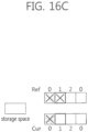
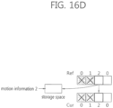
- Figs. 16a to 16g are views schematically illustrating another exemplary process of deriving motion information using motion information stored in a storage space.
- Figs. 16a to 16g illustrate an exemplary process of deriving motion information in the case where a sub prediction unit of the reference block comes from which motion information cannot be derived, followed by another sub prediction unit of the reference block from which motion information can be derived.
- Fig. 16a is a view illustrating the initial state of sub prediction units of a current block and a storage space.
- Ref denotes a reference block
- Ref 0, 1, 2, and 3 respectively denote sub prediction units in the reference block. That is, Ref 0 means sub prediction unit 0 of the reference block, Ref 1 sub prediction unit 1 of the reference block, Ref 2 sub prediction unit 2 of the reference block, and Ref 3 sub prediction unit 3 of the reference block.
- Cur denotes the current block
- Cur 0, 1, 2, and 3 respectively denote sub prediction units in the current block. That is, Cur 0 means sub prediction unit 0 of the current block, Cur 1 sub prediction unit 1 of the current block, Cur 2 sub prediction unit 2 of the current block, and Cur 3 sub prediction unit 3 of the current block.
- 'X' marked in Ref 0 of Fig. 16a denotes motion information being impossible to derive using sub prediction unit 0 of the reference block and sub prediction unit 1 of the reference block.
- Fig. 16e shows a fourth step of deriving motion information from a sub prediction unit of the reference block.
- motion information is derived using motion information 2 stored in the storage space for sub prediction unit 0 of the current block.
- motion information is derived from sub prediction unit 3 of the reference block for sub prediction unit 3 of the current block.
- motion information on sub prediction unit 3 of the reference block is stored in the storage space.
- the stored motion information on sub prediction unit 3 may be defined as motion information 3, and motion information 3 may be stored in the storage space instead of motion information 2.
- Motion information 3 may be used when motion information cannot be derived from some other sub prediction unit of the reference block.
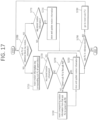
- the inter prediction module determines whether the storage space stores motion information (S1720). If the storage space stores motion information, step S1750 is performed. In this case, the storage space has been described above in detail, so has the motion information.
- the inter prediction module determines whether the sub prediction unit of the current block, which is targeted for deriving motion information, is the first sub prediction unit of the current block (S1730). If the sub prediction unit of the current block targeted for deriving motion information is the first sub prediction unit of the current block, the inter prediction module performs step S1750.
- step S1730 unless the sub prediction unit of the current block is the first sub prediction unit, the inter prediction module inserts the motion information present in the sub prediction unit of the reference block into the sub prediction unit(s) of the current block that are positioned ahead of the first sub prediction unit of the current block. For example, if the sub prediction unit of the current block. which is targeted for deriving motion information, is the third sub prediction unit, the inter prediction module inserts the motion information on the sub prediction unit of the reference block into the first and second sub prediction units of the current block.
- the inter prediction module stores (and updates the existing information in the storage space with) the motion information on the sub prediction unit of the reference block in the storage space (S1750).
- S1750 the storage space
- the inter prediction module determines whether the sub prediction unit of the reference block which is targeted for deriving motion information is the last sub prediction unit of the reference block (S1790). If the sub prediction unit of the reference block which is targeted for deriving motion information is the last sub prediction unit of the reference block, the inter prediction module terminates the motion information deriving process. Unless the sub prediction unit of the reference block which is targeted for deriving motion information is the last sub prediction unit of the reference block, the inter prediction module goes to a next sub prediction unit of the reference block for processing (S1780). Thereafter, the inter prediction module repeats steps S1700 to S1790.
- the inter prediction module determines whether a sub prediction unit of the reference block has motion information (S1700).
- the inter prediction module determines whether the storage space retains motion information (S1770). Unless the storage space retains motion information, the inter prediction module performs step S1790.
- the inter prediction module inserts the motion information stored in the storage space into the sub prediction unit of the reference block which is targeted for deriving motion information (S1750).
- the inter prediction module determines whether the sub prediction unit of the reference block which is targeted for deriving motion information is the last sub prediction unit of the reference block (S1790). If the sub prediction unit of the reference block which is targeted for deriving motion information is the last sub prediction unit of the reference block, the inter prediction module terminates the motion information deriving process. Unless the sub prediction unit of the reference block which is targeted for deriving motion information is the last sub prediction unit of the reference block, the inter prediction module goes to a next sub prediction unit of the reference block for processing (S1780). Thereafter, the inter prediction module repeats steps S1700 to S1790.
- the inter prediction module derives a prediction sample for the current block based on the motion information on the current block derived by the above steps.
- the prediction sample may mean the above-described prediction signal, and the prediction signal may mean a difference between the original signal and the residual signal as described above.
- the above-described process of deriving motion information on a sub prediction unit of a current block may specifically apply to 3D images as shown in Table 1.
- the operation shown in Table 1 may be performed by an encoder/decoder or an inter prediction module of the encoder/decoder.
- This process has the following inputs. - Position (xPb, yPb) of left and upper end of current prediction unit - Width (nPbW) and height of current prediction unit - Reference view index refViewIdx - Disparity vector mvDisp
- This process has the following outputs.
- - Flag availableFlagLXinterView for determining whether temporal inter-view motion candidate is available, where LX may be reference picture list L0 and Ll.
- 'temporal inter-view means that a picture at a different view from that of the current picture may be referenced as a picture at other time (i.e., other POC) at the same view as the current picture.
- mvLXInterView where LX may be reference picture lists L0 and L1.
- - Reference index refldxLXInterView designating a reference picture present in reference picture list RefPicListLX, where LX may be reference picture lists L0 and L1.
- LX may be reference picture lists L0 and L1.
- - Flag availableFlagLXinterView is initialized as 0.
- Motion vector mvLXInterView is initialized as (0,0).
- nSbW and nSbH are initialized as follows.
- nSbW Min(nPbW, SubPbSize)
- nSbH Min(nPbH, SubPbSize)
- Variable ivRefPic is initialized as a picture having the same ViewIdx as refviewldx in the current access unit.
- Variable curSubBlockIdx is initialized as 0, and variable lastAvailableFlag is initialized as 0. The following applies to yBlk ranging from 0 to (nPbH/nSbH-1) and xBlk ranging from 0 to (nPbW/nSbW-1).
- - Variable curAvailableFlag is initialized as 0. - The following applies to X ranging from 0 to 1. - Flag spPredFlagL1 [xBlk] [yBlk] is initialized as 0. - Motion vector spMvLX is initialized as (0,0). - Reference index spRefIdxLX[xBlk][yBlk] is initialized as -1. - Reference block position (xRef, yRef) is derived as follows.
- xRef Clip3(0, PicWidthInSamplesL-1), xPb+xBlk*nSbW+nSbW/2+((mvDisp[0]+2)>>2))
- yRef Clip3(0, PicHeightInSamplesL-1, yPb+yBlk*nSbH+nSbH/2+((mvDisp[1]+2)>>2))
- Variable ivRefPb refers to luma prediction block at (xRef, yRef) in the inter-view reference picture indicated by ivRefPic.
- - (xIvRefPb, yIvRefPb) refers to the left and upper position of the reference block indicated by ivRefPb. - Unless ivRefPb has been encoded in intra mode, the following is performed on X ranging from 0 to 1. - When X is 0 or current slice is slice B, the following is performed on Y ranging from X to (1-X).
- refPixListLYIvRef predFlagLYIvRef[x][y], mvLYIvRef[x][y], and refIdxLYIvRef[x][y], respectively, are set to RefPicListLY, PredFlagLY[x][y], MvLY[x][y], and RefIdxLY[x][y] in the picture indicated by ivRefPic.
- predFlagLYIvRef[xIvRefPb][yIvRefPb] is 1, the following is performed on i ranging from 0 to num_ref_idx_1X_active_minus1 (the number of reference pictures in reference picture list).
- curAvailableFlag 1
- curAvailableFlag 1
- curAvailableFlag 1
- curSubBlockIdx is larger than 0, the following applies to k ranging from 0 to (curSubBlockIdx-1).
- Variable lastAvailableFlag is replaced with 1.
- xBlk and yBlk are stored in variables xLastAvail and yLastAvail, respectively. - If curAvailableFlag is 0, and lastAvailableFlag is 1, the following applies to X ranging from 0 to 1.
- curSubBlockIdx is set to curSubBlockIdx+1.
- the information for identifying whether to predict motion information from the sub prediction unit of the reference block may be defined as 'curAvailableFlag.
- the sub prediction unit prediction flag may be set to 0, and the sub prediction unit prediction flag may be defined as 'spPredFlagL1.
- the sub prediction unit flag may be defined as 'spPredFlagL1[ xBlk][yBlk].
- the motion vector of the sub prediction unit is set to (0, 0), and the motion vector of the sub prediction unit may be defined as 'spMvLX.
- the reference index of the sub prediction unit may be set to -1, and the reference index of the sub prediction unit may be defined as 'spRefIdxLX.
- the reference index of the sub prediction unit may be defined as 'spRefIdxLX[ xBlk ][ yBlk ].'
- predFlagLYIvRef[xIvRefPb][yIvRefPb] 1, the following may apply to i ranging from 0 to num_ref_idx_1X_active_minus1 (the number of reference pictures in reference picture list).
- POC Physical Order Count
- refPicListLYIvRef[refIdxLYIvRef[xIvRefPb][yIvRefPb]] is the same as RefPicListLX[i] and centerPredFlag is 0, the following applies.
- curAvailableFlag - If curAvailableFlag is 0, the following applies to X ranging from 0 to 1.
- Variable curSubBlockIdx is set to curSubBlockIdx+1.
- the inter prediction module 2100 performs initialization before deriving motion information on a current sub prediction unit using a sub prediction unit of a reference block.
- the initialization is the same as that described above in connection with Table 2.
- the inter prediction module 2100 initializes the information for identifying whether to predict motion information from a sub prediction unit of the reference block, the sub prediction unit prediction flag, motion information on the sub prediction unit, and reference index of the sub prediction unit.
- the initialization is the same as that described above in connection with Table 2.
- the position (xRef, yRef) of the reference block is reset as shown in Equation 25 on a per-sub prediction unit basis.
- the inter prediction module 2100 may perform the following process on X that ranges from 0 to 1.
- each variable is reset for Y (Y ranges from X to (1-X)) as described above in connection with Table 2.
- Equation 26 may apply to i ranging from 0 to num_ref_idx_1X_active_minus1(the number of reference pictures in the reference picture list).
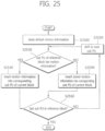
- the inter prediction module 2100 may derive motion information on the sub prediction unit of the current block from the arbitrarily set default motion information.
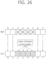
- the blocks positioned at the upper end of Fig. 26 mean sub prediction units of the reference block, and the blocks positioned at the lower end of Fig. 26 mean sub prediction units of the current block. Further, default motion information is stored in a storage space.
- the default motion information shown in Fig. 26 may mean default motion information arbitrarily set according to embodiment 3.
- the inter prediction module 2100 derives motion information using the default motion information with a value. Accordingly, the motion information deriving method according to embodiment 3 enables independent derivation of motion information on each sub prediction unit in the reference block. In other words, embodiment 3 does not require sequential discovery of sub prediction units from which motion information may be derived in order to find sub prediction units from which motion information may be derived, and in case the first sub prediction unit of the reference block is impossible to use for deriving motion information, embodiment 3 derives motion information on the sub prediction unit of the current block using predetermined motion information. As such, the motion information derivation according to embodiment 3 removes data dependency, enabling parallelized derivation of motion information on each sub prediction unit. Further, the motion information derivation according to embodiment 3 prevents additional memory access in contrast to existing motion information deriving methods, thus reducing the number of times of accessing the memory.
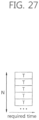
- Fig. 27 is a view schematically illustrating times required to derive motion information according to the present invention.
- the motion information derivation may be parallelized, and thus, the time of deriving motion information corresponds to T and a 3D image encoding/decoding delay is reduced.
- the above-described embodiments may have different applicable ranges depending on block sizes, coding unit (CU) depths, or transform unit (TU) depths.
- CU coding unit
- TU transform unit
- the variable for determining an applicable range a value predetermined in the encoder/decoder or a value determined according to a profile or level may be used, or if the encoder specifies a variable value in the bitstream, the decoder may obtain the variable value from the bitstream.
- an indicator may be used to indicate the same, or it may be indicated with a CU depth that the methods according to the present invention do not apply, where the CU depth may be set to be larger than the maximum depth that the CU may have.
- the methods are described based on the flowcharts with a series of steps or units, but the present invention is not limited to the order of the steps, and rather, some steps may be performed simultaneously or in different order with other steps. It should be appreciated by one of ordinary skill in the art that the steps in the flowcharts do not exclude each other and that other steps may be added to the flowcharts or some of the steps may be deleted from the flowcharts without influencing the scope of the present invention.
- the above-described methods according to the present invention may be prepared in a computer executable program that may be stored in a computer readable recording medium, examples of which include a ROM, a RAM, a CD-ROM, a magnetic tape, a floppy disc, or an optical data storage device, or may be implemented in the form of a carrier wave (for example, transmission through the Internet).
- a computer readable recording medium examples of which include a ROM, a RAM, a CD-ROM, a magnetic tape, a floppy disc, or an optical data storage device, or may be implemented in the form of a carrier wave (for example, transmission through the Internet).
- the computer readable recording medium may be distributed in computer systems connected over a network, and computer readable codes may be stored and executed in a distributive way.
- the functional programs, codes, or code segments for implementing the above-described methods may be easily inferred by programmers in the art to which the present invention pertains.
- a method of encoding a three-dimensional (3D) image comprising:
- An apparatus of encoding a three-dimensional (3D) image comprising:
- a method of decoding a three-dimensional (3D) image comprising:
- An apparatus of decoding a three-dimensional (3D) image comprising:
Landscapes
- Engineering & Computer Science (AREA)
- Multimedia (AREA)
- Signal Processing (AREA)
- Physics & Mathematics (AREA)
- General Physics & Mathematics (AREA)
- Theoretical Computer Science (AREA)
- Computer Vision & Pattern Recognition (AREA)
- Compression Or Coding Systems Of Tv Signals (AREA)
- Compression, Expansion, Code Conversion, And Decoders (AREA)
Applications Claiming Priority (4)
| Application Number | Priority Date | Filing Date | Title |
|---|---|---|---|
| KR20140000527 | 2014-01-03 | ||
| KR20140001531 | 2014-01-06 | ||
| PCT/KR2015/000050 WO2015102443A1 (ko) | 2014-01-03 | 2015-01-05 | 서브 예측 유닛 단위의 시간적인 시점 간 움직임 정보 유도의 방법 및 장치 |
| EP15733249.5A EP3091743B1 (de) | 2014-01-03 | 2015-01-05 | Verfahren und vorrichtung zur induktion von bewegungsinformationen zeitlichen punkten einer untergeordneten vorhersageeinheit |
Related Parent Applications (2)
| Application Number | Title | Priority Date | Filing Date |
|---|---|---|---|
| EP15733249.5A Division EP3091743B1 (de) | 2014-01-03 | 2015-01-05 | Verfahren und vorrichtung zur induktion von bewegungsinformationen zeitlichen punkten einer untergeordneten vorhersageeinheit |
| EP15733249.5A Division-Into EP3091743B1 (de) | 2014-01-03 | 2015-01-05 | Verfahren und vorrichtung zur induktion von bewegungsinformationen zeitlichen punkten einer untergeordneten vorhersageeinheit |
Publications (2)
| Publication Number | Publication Date |
|---|---|
| EP4518322A2 true EP4518322A2 (de) | 2025-03-05 |
| EP4518322A3 EP4518322A3 (de) | 2025-05-07 |
Family
ID=53793011
Family Applications (3)
| Application Number | Title | Priority Date | Filing Date |
|---|---|---|---|
| EP15733249.5A Active EP3091743B1 (de) | 2014-01-03 | 2015-01-05 | Verfahren und vorrichtung zur induktion von bewegungsinformationen zeitlichen punkten einer untergeordneten vorhersageeinheit |
| EP24222162.0A Pending EP4550795A1 (de) | 2014-01-03 | 2015-01-05 | Verfahren und vorrichtung zur induktion von bewegungsinformationen zeitlichen punkten einer untergeordneten vorhersageeinheit |
| EP24222383.2A Pending EP4518322A3 (de) | 2014-01-03 | 2015-01-05 | Verfahren und vorrichtung zur induzierung von bewegungsinformationen zwischen zeitlichen punkten einer untervorhersageeinheit |
Family Applications Before (2)
| Application Number | Title | Priority Date | Filing Date |
|---|---|---|---|
| EP15733249.5A Active EP3091743B1 (de) | 2014-01-03 | 2015-01-05 | Verfahren und vorrichtung zur induktion von bewegungsinformationen zeitlichen punkten einer untergeordneten vorhersageeinheit |
| EP24222162.0A Pending EP4550795A1 (de) | 2014-01-03 | 2015-01-05 | Verfahren und vorrichtung zur induktion von bewegungsinformationen zeitlichen punkten einer untergeordneten vorhersageeinheit |
Country Status (11)
| Country | Link |
|---|---|
| US (7) | US10681369B2 (de) |
| EP (3) | EP3091743B1 (de) |
| JP (6) | JP6616773B2 (de) |
| KR (10) | KR101710034B1 (de) |
| CN (6) | CN110855992B (de) |
| DK (1) | DK3091743T3 (de) |
| ES (1) | ES3041933T3 (de) |
| FI (1) | FI3091743T3 (de) |
| HU (1) | HUE072139T2 (de) |
| PL (1) | PL3091743T3 (de) |
| RU (1) | RU2680204C2 (de) |
Families Citing this family (9)
| Publication number | Priority date | Publication date | Assignee | Title |
|---|---|---|---|---|
| CN110855992B (zh) | 2014-01-03 | 2024-06-07 | 庆熙大学校产学协力团 | 导出子预测单元的时间点之间的运动信息的方法和装置 |
| CN116962717A (zh) | 2018-03-14 | 2023-10-27 | Lx 半导体科技有限公司 | 图像编码/解码方法、存储介质和发送方法 |
| CN118200541A (zh) * | 2018-04-01 | 2024-06-14 | Lg电子株式会社 | 图像编码/解码设备、数据的发送设备以及存储介质 |
| US12348762B2 (en) | 2018-06-19 | 2025-07-01 | Qualcomm Incorporated | Signaling sub-prediction unit motion vector predictor |
| US11800089B2 (en) * | 2019-01-02 | 2023-10-24 | Lg Electronics Inc. | SbTMVP-based inter prediction method and apparatus |
| WO2020141881A1 (ko) * | 2019-01-02 | 2020-07-09 | 엘지전자 주식회사 | 서브블록 단위의 움직임 정보 기반 인터 예측 방법 및 장치 |
| US12549765B2 (en) * | 2019-06-25 | 2026-02-10 | Electronics And Telecommunications Research Institute | Image encoding/decoding method and apparatus |
| KR102612539B1 (ko) * | 2019-12-17 | 2023-12-11 | 한국전자통신연구원 | 다시점 비디오 부호화 및 복호화 방법 |
| KR20240051491A (ko) | 2022-10-13 | 2024-04-22 | 엘지디스플레이 주식회사 | 표시 장치 |
Family Cites Families (27)
| Publication number | Priority date | Publication date | Assignee | Title |
|---|---|---|---|---|
| TW312770B (en) * | 1996-10-15 | 1997-08-11 | Japen Ibm Kk | The hiding and taking out method of data |
| RU2395174C1 (ru) | 2006-03-30 | 2010-07-20 | ЭлДжи ЭЛЕКТРОНИКС ИНК. | Способ и устройство для декодирования/кодирования сигнала видео |
| JP4752631B2 (ja) | 2006-06-08 | 2011-08-17 | 株式会社日立製作所 | 画像符号化装置、及び画像符号化方法 |
| CN101647279A (zh) * | 2007-01-24 | 2010-02-10 | Lg电子株式会社 | 用于处理视频信号的方法和装置 |
| CN101267556B (zh) * | 2008-03-21 | 2011-06-22 | 海信集团有限公司 | 快速运动估计方法及视频编解码方法 |
| WO2009139569A2 (ko) * | 2008-05-13 | 2009-11-19 | 엘지전자(주) | 비디오 신호 디코딩 방법 및 장치 |
| JP2010016454A (ja) * | 2008-07-01 | 2010-01-21 | Sony Corp | 画像符号化装置および方法、画像復号装置および方法、並びにプログラム |
| KR20110071047A (ko) * | 2009-12-20 | 2011-06-28 | 엘지전자 주식회사 | 비디오 신호 디코딩 방법 및 장치 |
| JP2011259040A (ja) * | 2010-06-04 | 2011-12-22 | Sony Corp | 画像処理装置および方法 |
| CN103314587B (zh) * | 2010-10-28 | 2017-02-22 | 韩国电子通信研究院 | 视频信息编码方法和解码方法 |
| HU1000640D0 (en) * | 2010-11-29 | 2011-02-28 | Holografika Hologrameloeallito Fejlesztoe Es Forgalmazo Kft | Image coding and decoding method and apparatus for efficient encoding and decoding of 3d field content |
| CN107071460B (zh) * | 2010-12-14 | 2020-03-06 | M&K控股株式会社 | 用于编码运动画面的设备 |
| JP2014501091A (ja) | 2010-12-17 | 2014-01-16 | エレクトロニクス アンド テレコミュニケーションズ リサーチ インスチチュート | インター予測方法及びその装置 |
| US9363535B2 (en) | 2011-07-22 | 2016-06-07 | Qualcomm Incorporated | Coding motion depth maps with depth range variation |
| CN104137549B9 (zh) * | 2012-01-18 | 2020-06-05 | 韩国电子通信研究院 | 对图像进行编码和解码的方法及设备 |
| US20130258052A1 (en) | 2012-03-28 | 2013-10-03 | Qualcomm Incorporated | Inter-view residual prediction in 3d video coding |
| JP2013207755A (ja) * | 2012-03-29 | 2013-10-07 | Sony Corp | 画像処理装置および方法 |
| EP2839639A4 (de) * | 2012-04-19 | 2016-01-06 | Intel Corp | 3d-videocodierung mit tiefenbasierter disparitätsvektorkalibrierung |
| CA2864002A1 (en) | 2012-04-24 | 2013-10-31 | Mediatek Inc. | Method and apparatus of motion vector derivation for 3d video coding |
| JP6039793B2 (ja) | 2012-05-10 | 2016-12-07 | エルジー エレクトロニクス インコーポレイティド | ビデオ信号処理方法及び装置 |
| US9420286B2 (en) * | 2012-06-15 | 2016-08-16 | Qualcomm Incorporated | Temporal motion vector prediction in HEVC and its extensions |
| EP2859724B1 (de) | 2012-06-22 | 2019-09-04 | MediaTek Inc. | Verfahren und vorrichtung zur adaptiven intraprädiktion für eine kodierung zwischen schichten |
| CN102984521B (zh) * | 2012-12-12 | 2015-04-08 | 四川大学 | 基于时域相关性的高性能视频编码帧间模式判决方法 |
| WO2015003383A1 (en) * | 2013-07-12 | 2015-01-15 | Mediatek Singapore Pte. Ltd. | Methods for inter-view motion prediction |
| SG11201510554RA (en) | 2013-07-24 | 2016-02-26 | Qualcomm Inc | Simplified advanced motion prediction for 3d-hevc |
| CN110855992B (zh) * | 2014-01-03 | 2024-06-07 | 庆熙大学校产学协力团 | 导出子预测单元的时间点之间的运动信息的方法和装置 |
| JP6616733B2 (ja) | 2016-05-10 | 2019-12-04 | エイチ・シー・ネットワークス株式会社 | ネットワークシステムおよびサーバ装置 |
-
2015
- 2015-01-05 CN CN201910681943.8A patent/CN110855992B/zh active Active
- 2015-01-05 CN CN201910681941.9A patent/CN110430432B/zh active Active
- 2015-01-05 HU HUE15733249A patent/HUE072139T2/hu unknown
- 2015-01-05 EP EP15733249.5A patent/EP3091743B1/de active Active
- 2015-01-05 CN CN201910682350.3A patent/CN110430433B/zh active Active
- 2015-01-05 CN CN201580003671.6A patent/CN105874798B/zh active Active
- 2015-01-05 ES ES15733249T patent/ES3041933T3/es active Active
- 2015-01-05 DK DK15733249.5T patent/DK3091743T3/da active
- 2015-01-05 CN CN202410414099.3A patent/CN118400532A/zh active Pending
- 2015-01-05 EP EP24222162.0A patent/EP4550795A1/de active Pending
- 2015-01-05 EP EP24222383.2A patent/EP4518322A3/de active Pending
- 2015-01-05 RU RU2016125782A patent/RU2680204C2/ru active
- 2015-01-05 KR KR1020150000578A patent/KR101710034B1/ko active Active
- 2015-01-05 FI FIEP15733249.5T patent/FI3091743T3/fi active
- 2015-01-05 JP JP2016544462A patent/JP6616773B2/ja active Active
- 2015-01-05 US US15/109,573 patent/US10681369B2/en active Active
- 2015-01-05 PL PL15733249.5T patent/PL3091743T3/pl unknown
- 2015-01-05 CN CN201910681940.4A patent/CN110381317B/zh active Active
-
2017
- 2017-02-20 KR KR1020170022192A patent/KR102179072B1/ko active Active
- 2017-02-20 KR KR1020170022191A patent/KR102179071B1/ko active Active
-
2019
- 2019-11-07 JP JP2019202688A patent/JP6941656B2/ja active Active
- 2019-11-07 JP JP2019202695A patent/JP6941657B2/ja active Active
-
2020
- 2020-04-24 US US16/857,519 patent/US10986359B2/en active Active
- 2020-04-24 US US16/857,531 patent/US11115674B2/en active Active
- 2020-11-10 KR KR1020200149041A patent/KR102321412B1/ko active Active
- 2020-11-10 KR KR1020200149042A patent/KR102299009B1/ko active Active
-
2021
- 2021-07-27 US US17/443,475 patent/US11711536B2/en active Active
- 2021-07-27 US US17/386,018 patent/US11627331B2/en active Active
- 2021-09-01 KR KR1020210116079A patent/KR102321413B1/ko active Active
- 2021-09-03 JP JP2021144086A patent/JP7183361B2/ja active Active
- 2021-09-03 JP JP2021144107A patent/JP7183362B2/ja active Active
- 2021-10-28 KR KR1020210145772A patent/KR102367799B1/ko active Active
-
2022
- 2022-02-22 KR KR1020220022847A patent/KR102446602B1/ko active Active
- 2022-09-20 KR KR1020220118305A patent/KR20220131215A/ko not_active Ceased
- 2022-11-15 JP JP2022182749A patent/JP7527334B2/ja active Active
-
2023
- 2023-06-05 US US18/329,014 patent/US12184882B2/en active Active
-
2024
- 2024-07-15 KR KR1020240092808A patent/KR20240115213A/ko not_active Ceased
- 2024-11-12 US US18/945,258 patent/US20250071314A1/en active Pending
Also Published As
Similar Documents
| Publication | Publication Date | Title |
|---|---|---|
| US12184882B2 (en) | Method and device for inducing motion information between temporal points of sub prediction unit | |
| CA2891672C (en) | Method and apparatus for deriving temporal inter-view motion information of sub-prediction unit |
Legal Events
| Date | Code | Title | Description |
|---|---|---|---|
| PUAI | Public reference made under article 153(3) epc to a published international application that has entered the european phase |
Free format text: ORIGINAL CODE: 0009012 |
|
| STAA | Information on the status of an ep patent application or granted ep patent |
Free format text: STATUS: THE APPLICATION HAS BEEN PUBLISHED |
|
| AC | Divisional application: reference to earlier application |
Ref document number: 3091743 Country of ref document: EP Kind code of ref document: P |
|
| AK | Designated contracting states |
Kind code of ref document: A2 Designated state(s): AL AT BE BG CH CY CZ DE DK EE ES FI FR GB GR HR HU IE IS IT LI LT LU LV MC MK MT NL NO PL PT RO RS SE SI SK SM TR |
|
| REG | Reference to a national code |
Ref country code: DE Ref legal event code: R079 Free format text: PREVIOUS MAIN CLASS: H04N0019700000 Ipc: H04N0019597000 |
|
| PUAL | Search report despatched |
Free format text: ORIGINAL CODE: 0009013 |
|
| AK | Designated contracting states |
Kind code of ref document: A3 Designated state(s): AL AT BE BG CH CY CZ DE DK EE ES FI FR GB GR HR HU IE IS IT LI LT LU LV MC MK MT NL NO PL PT RO RS SE SI SK SM TR |
|
| RIC1 | Information provided on ipc code assigned before grant |
Ipc: H04N 19/436 20140101ALN20250331BHEP Ipc: H04N 19/70 20140101ALI20250331BHEP Ipc: H04N 19/176 20140101ALI20250331BHEP Ipc: H04N 19/159 20140101ALI20250331BHEP Ipc: H04N 19/52 20140101ALI20250331BHEP Ipc: H04N 19/597 20140101AFI20250331BHEP |
|
| STAA | Information on the status of an ep patent application or granted ep patent |
Free format text: STATUS: REQUEST FOR EXAMINATION WAS MADE |
|
| 17P | Request for examination filed |
Effective date: 20251107 |