EP4518345A1 - Dienstdatenverarbeitungsverfahren und -vorrichtung - Google Patents
Dienstdatenverarbeitungsverfahren und -vorrichtung Download PDFInfo
- Publication number
- EP4518345A1 EP4518345A1 EP23814949.6A EP23814949A EP4518345A1 EP 4518345 A1 EP4518345 A1 EP 4518345A1 EP 23814949 A EP23814949 A EP 23814949A EP 4518345 A1 EP4518345 A1 EP 4518345A1
- Authority
- EP
- European Patent Office
- Prior art keywords
- code block
- code
- service data
- timeslot
- overhead
- Prior art date
- Legal status (The legal status is an assumption and is not a legal conclusion. Google has not performed a legal analysis and makes no representation as to the accuracy of the status listed.)
- Pending
Links
Images





Classifications
-
- H—ELECTRICITY
- H04—ELECTRIC COMMUNICATION TECHNIQUE
- H04J—MULTIPLEX COMMUNICATION
- H04J14/00—Optical multiplex systems
- H04J14/08—Time-division multiplex systems
-
- H—ELECTRICITY
- H04—ELECTRIC COMMUNICATION TECHNIQUE
- H04J—MULTIPLEX COMMUNICATION
- H04J3/00—Time-division multiplex systems
- H04J3/16—Time-division multiplex systems in which the time allocation to individual channels within a transmission cycle is variable, e.g. to accommodate varying complexity of signals, to vary number of channels transmitted
- H04J3/1605—Fixed allocated frame structures
- H04J3/1652—Optical Transport Network [OTN]
-
- H—ELECTRICITY
- H04—ELECTRIC COMMUNICATION TECHNIQUE
- H04J—MULTIPLEX COMMUNICATION
- H04J3/00—Time-division multiplex systems
- H04J3/02—Details
- H04J3/06—Synchronising arrangements
- H04J3/07—Synchronising arrangements using pulse stuffing for systems with different or fluctuating information rates or bit rates
-
- H—ELECTRICITY
- H04—ELECTRIC COMMUNICATION TECHNIQUE
- H04J—MULTIPLEX COMMUNICATION
- H04J2203/00—Aspects of optical multiplex systems other than those covered by H04J14/05 and H04J14/07
- H04J2203/0001—Provisions for broadband connections in integrated services digital network using frames of the Optical Transport Network [OTN] or using synchronous transfer mode [STM], e.g. SONET, SDH
- H04J2203/0073—Services, e.g. multimedia, GOS, QOS
- H04J2203/0082—Interaction of SDH with non-ATM protocols
- H04J2203/0085—Support of Ethernet
-
- H—ELECTRICITY
- H04—ELECTRIC COMMUNICATION TECHNIQUE
- H04Q—SELECTING
- H04Q2213/00—Indexing scheme relating to selecting arrangements in general and for multiplex systems
- H04Q2213/1301—Optical transmission, optical switches
Definitions
- This application relates to the optical communication field, and more specifically, to a service data processing method and an apparatus.
- the service data processing method is provided.
- the method may be performed by a transmitting end device, or may be performed by a component (for example, a chip or a circuit) of the transmitting end device.
- a component for example, a chip or a circuit
- the transmitting end device is a device that sends an OTN frame, and may be a source end processing device, or may be an intermediate device.
- the service data processing method includes: receiving service data, performing encapsulation, rate matching, and timeslot multiplexing on the service data by code block to obtain an intermediate frame, mapping the intermediate frame that carries the service data to an OTN frame, and sending the OTN frame, where a size of the code block is a plurality of bytes, the code block includes first information, the first information indicates a code block type of the code block, when the code block type of the code block is an overhead code block or a rate adaptation code block, the code block further includes second information, and the second information indicates a timeslot multiplexing layer at which the code block is located.
- the transmitting end device in a process of processing the received service data, ensures that the code block is used as a granularity in different processing procedures (for example, encapsulation, rate matching, and timeslot multiplexing) of the service data. This reduces complexity of service data processing.
- the code block carries information indicating the code block type, or may further carry information indicating the timeslot multiplexing layer at which the code block is located. This facilitates a device identifying the code blocks of different code block types, and determining whether the code block needs to be processed (for example, deleting the code block or subtracting 1 from a value of second information of the code block).
- the first information includes first indication information and second indication information
- the first indication information indicates that the code block is a data code block or a non-data code block
- the second indication information indicates that the non-data code block is an overhead code block or a rate adaptation code block
- the first information may be a field, in other words, a function of the first information may be implemented in different manners, and this improves flexibility of the solution.
- the second information occupies n bits, and a value of n is any positive integer from 1 to 8. There may be a plurality of values of the second information, and nested timeslot multiplexing of different layers is supported.
- the performing encapsulation, rate matching, and timeslot multiplexing on the service data by code block to obtain an intermediate frame includes: dividing the service data into one or more data code blocks based on the size of the code block; encapsulating the one or more data code blocks into a data frame, where the 1 st column of the data frame is a first overhead code block, and the first overhead code block is used to manage the one or more data code blocks; inserting a rate adaptation code block into the data frame for rate matching, to obtain a first code stream; and performing timeslot multiplexing based on the first code stream and at least one second code stream to obtain the intermediate frame, where the 1 st column of the intermediate frame is a second overhead code block, the second overhead code block is used to manage the first code stream and the at least one second code stream, and sizes of the data code block, the rate adaptation code block, the first overhead code block, and the second overhead code block are equal to the size of the code block.
- the sizes of the code blocks (for example, the data code block, the rate adaptation code block, and the overhead code block) involved in each service data processing procedure are equal to the defined size of the code block, so that the service data is processed at a uniform code block processing granularity, and the complexity of service data processing is reduced.
- the inserting a rate adaptation code block into the data frame for rate matching includes: determining a status of a cache allocated to the service data; when the status of the cache is empty, inserting the rate adaptation code, setting a value of second information of the inserted rate adaptation code to 0, and outputting the rate adaptation code; when a first code block is cached in the cache, determining whether the first code block is the rate adaptation code; when the first code block is the rate adaptation code, outputting the first code block after adding 1 to a value of second information of the first code block; and when the first code block is not the rate adaptation code, outputting the first code block.
- the value of the second information of the rate adaptation code block is set, indicating a device that receives the rate adaptation code block to determine whether the rate adaptation code block needs to be processed.
- a size of the code block is a plurality of bytes includes any one of the following: the size of the code block is 64, 128, 192, 240, or 256 bytes.
- the code block that is defined in the uniform size may have a plurality of possible values, to support service data transmission at different rates.
- the receiving end device After receiving the OTN frame, in a process of obtaining the service data from the OTN frame, the receiving end device ensures that the code block is used as a granularity in different processing procedures (for example, encapsulation, rate matching, and timeslot multiplexing) for obtaining the service data. This reduces complexity of obtaining the service data.
- the deleting the rate adaptation code block from the first code stream includes: determining whether a third code block in the first code stream is the rate adaptation code block; when the third code block is not a rate adaptation code, outputting the third code block; when the third code block is the rate adaptation code, determining whether a value of second information of the third code block is 0; when the value of the second information of the third code block is 0, deleting the third code block; and when the value of the second information of the third code block is not 0, outputting the third code block after subtracting 1 from the value of the second information of the third code block.
- the receiving end device may determine, based on the value of the second information in the rate adaptation code block, whether to delete the rate adaptation code block, or determine whether to transmit the rate adaptation code block to a next-hop node for processing.
- the performing timeslot demultiplexing on a plurality of code streams includes: determining whether a fourth code block in the code stream is the overhead code block; when the fourth code block is not the overhead code block, determining an identifier of a timeslot corresponding to the fourth code block, determining, based on a timeslot configuration table and the identifier of the timeslot, a cache allocated to first service data, and outputting the fourth code block to the cache; when the fourth code block is the overhead code block, determining whether a value of second information of the fourth code block is 0; when the value of the second information of the fourth code block is 0, deleting the fourth code block; and when the value of the second information of the fourth code block is not 0, outputting the fourth code block to the cache after subtracting 1 from the value of the second information of the fourth code block, where the timeslot configuration table includes a correspondence between an identifier of a timeslot and an identifier of the cache allocated to the first service data, and the first
- a service data processing apparatus is provided, and the apparatus is configured to perform the method provided in the first aspect.
- the service data processing apparatus may include units and/or modules configured to perform the method provided in any one of the first aspect or the foregoing implementations of the first aspect, for example, a processing unit and an obtaining unit.
- the service data processing apparatus is a transmitting end device.
- the obtaining unit may be a transceiver or an input/output interface, and the processing unit may be at least one processor.
- the transceiver may be a transceiver circuit.
- the input/output interface may be an input/output circuit.
- beneficial effects of the method shown in the third aspect and the possible designs of the third aspect refer to beneficial effects in the first aspect and the possible designs of the first aspect.
- the service data processing apparatus is a receiving end device.
- the obtaining unit may be a transceiver or an input/output interface, and the processing unit may be at least one processor.
- the transceiver may be a transceiver circuit.
- the input/output interface may be an input/output circuit.
- the service data processing apparatus is a chip, a chip system, or a circuit in the receiving end device.
- the obtaining unit may be an input/output interface, an interface circuit, an output circuit, an input circuit, a pin, a related circuit, or the like on the chip, the chip system, or the circuit.
- the processing unit may be at least one processor, a processing circuit, a logic circuit, or the like.
- this application provides a processor, configured to perform the method according to each of the foregoing aspects.
- Operations like sending and obtaining/receiving related to the processor may be understood as operations like outputting and receiving or inputting of the processor, or operations like transmitting and receiving performed by a radio frequency circuit and an antenna, unless otherwise specified, or provided that the operations do not contradict actual functions or internal logic of the operations in related descriptions. This is not limited in this application.
- a computer-readable storage medium stores program code executed by a device, and the program code includes the method provided in any one of the implementations of the first aspect or the second aspect.
- a computer program product including instructions is provided.
- the computer program product is run on a computer, the computer is enabled to perform the method provided in any one of the implementations of the first aspect or the second aspect.
- a chip includes a processor and a communication interface.
- the processor reads, through the communication interface, instructions stored in a memory, to perform the method provided in any one of the implementations of the first aspect or the second aspect.
- the chip further includes the memory, the memory stores a computer program or instructions, the processor is configured to execute the computer program or the instructions stored in the memory, and when the computer program or the instructions is or are executed, the processor is configured to perform the method provided in any one of the implementations of the first aspect or the second aspect.
- a communication system including a service data processing apparatus according to the third aspect and a service data processing apparatus according to the fourth aspect.
- FIG. 1 is a diagram of an application scenario to which this application is applicable.
- the technical solutions in embodiments of this application may be applied to a communication system 100 including an OTN and a plurality of customer devices (for example, a customer device #1 to a customer device #6 shown in FIG. 1 ).
- the OTN includes a plurality of interconnected OTN devices (an OTN device #1 to an OTN device #4 shown in FIG. 1 ).
- FIG. 1 shows only the OTN devices configured to connect to the customer devices.
- the OTN may further include more OTN devices, for example, another OTN device exists between the OTN devices (for example, an OTN device connected to the OTN device #1 and the OTN device #3 shown in FIG. 1 exists between the OTN device #1 and the OTN device #3), which is not shown in FIG. 1 .
- FIG. 1 does not show a specific connection relationship between the OTN devices. Specifically, for a connection manner between the OTN devices, refer to descriptions in a current related technology. Details are not described in this application.
- the OTN devices in an OTN network are connected through an optical fiber, and may form different topology types such as a linear topology, a ring topology, and a mesh topology according to a specific requirement.
- the customer device may also be referred to as a customer premise equipment (customer premise equipment, CPE).
- CPE customer premise equipment
- a specific form of the customer device is not limited in this application, and the customer device includes but is not limited to a terminal communicating with an OTN device.
- the terminal may also be referred to as a subscriber unit, a subscriber station, a mobile station, a wireless communication device, a user agent, or a user apparatus.
- the customer device may be a device that needs to transmit service data.
- OTN devices are classified into an optical-layer device, an electrical-layer device, and an electro-optical hybrid device.
- the optical-layer device is a device that can process an optical-layer signal, like an optical amplifier (optical amplifier, OA) or an optical add-drop multiplexer (optical add-drop multiplexer, OADM).
- the OA is also called an optical line amplifier (optical line amplifier, OLA), and is mainly used to amplify an optical signal to support a longer transmission distance while ensuring specific performance of the optical signal.
- OLA optical line amplifier
- the OADM is configured to perform spatial conversion on an optical signal, so that the optical signal can be output from different output ports (sometimes also referred to as directions).
- the OADMs may be classified into a fixed OADM (fixed OADM, FOADM) and a configurable OADM (reconfigurable OADM, ROADM).
- the electrical-layer device is a device that can process an electrical-layer signal, for example, a device that can process an OTN electrical signal.
- the electro-optical hybrid device is a device that has a capability of processing an optical-layer signal and an electrical-layer signal.
- FIG. 2 is a diagram of a structure of an optical transport device.
- the optical transport device shown in FIG. 2 is one of the OTN device #1 to the OTN device #4 in FIG. 1 .
- an OTN device 200 includes a power supply 201, a fan 202, and an auxiliary board 203, and may further include a tributary board 204, a line board 206, a cross-connect board 205, an optical-layer processing board 208, and a system control and communication board 207.
- a network device serving as a core node may not have the tributary board 204; and for another example, a network device serving as an edge node may have a plurality of tributary boards 204.
- the power supply 201 is configured to supply power to the OTN device 200, and may include an active power supply and a standby power supply.
- the fan 202 is configured to dissipate heat for a device.
- the auxiliary board 203 is configured to provide an auxiliary function, for example, an external alarm or accessing an external clock.
- the tributary board 204, the cross-connect board 205, and the line board 206 are mainly configured to process an electrical-layer signal of an OTN.
- the tributary board 204 is configured to implement receiving and sending of various customer services, for example, an SDH service, a packet service, an Ethernet service, and a forward service. Further, the tributary board 204 may be divided into a customer-side optical module and a signal processor.
- the customer-side optical module may be an optical transceiver, configured to receive and/or send service data.
- the signal processor is configured to map service data to a data frame and demap the service data from the data frame.
- the cross-connect board 205 is configured to implement switching of data frames, and complete switching of one or more types of data frames.
- the line board 206 mainly implements processing of a line-side data frame.
- the line board 206 may be divided into a line-side optical module and a signal processor.
- the line-side optical module may be a line-side optical transceiver, configured to receive and/or send a data frame.
- the signal processor is configured to multiplex and demultiplex, or map and demap a line-side frame.
- the system control and communication board 207 is configured to implement system control and communication. Specifically, the system control and communication board 207 may collect information from different boards by using a backplane, or send control instructions to a corresponding board.
- FIG. 2 merely provides an example of a possible structure of the OTN device, and does not constitute any limitation on the protection scope of this application.
- the structure of the OTN device is not limited in this application, and the OTN device may be an existing OTN device or an OTN device in the future when the OTN is developed.
- the method provided in embodiments of this application may be applied to an optical transport network, for example, a communication system shown in FIG. 1 .
- a scenario to which the method can be applied is not limited in embodiments of this application.
- the method is also applicable to another communication system including a device (for example, an OTN device or another communication device) that can implement a corresponding function.
- Cn represents a variable rate, which is specifically a rate that is a positive integer multiple of 100 Gbps.
- the ODU frame refers to any one of the ODUk, ODUCn, or ODUflex frame
- the OTU frame refers to any one of the OTUk, OTUCn, or FlexO frame.
- FIG. 3 is a diagram of multiplexing a low-rate service into a high-rate signal.
- a plurality of E1 signals are first mapped to a synchronous transport module-1 (synchronous transport module-1, STM-1) interface signal.
- STM-1 synchronous transport module-1, STM-1) interface signal.
- the STM-1 is a type of SDH signal.
- the STM-1 interface signal is then mapped into an ODUO, and then transmission of the STM-1 interface signal is performed in the OTN through an OTU1.
- the error tolerance capability is a capability of using a fault tolerance technology to enable a computer system to continue to run properly in the case of error occurrence.
- the error tolerance capability may also be referred to as an error correction capability.
- a specific structure of an execution body of the method provided in embodiments of this application is not particularly limited in the following embodiments, provided that a program that records code of the method provided in embodiments of this application can be run to perform communication according to the method provided in embodiments of this application.
- the execution body of the method provided in embodiments of this application may be an OTN device, or a functional module that can invoke and execute a program in the OTN device, or may be another communication device.
- indicate may include directly indicating and indirectly indicating.
- the information may directly indicate A or indirectly indicate A, but it does not indicate that the information definitely carries A.
- “at least one” shown in this application means one or more, and "a plurality of” means two or more.
- “And/or” describes an association relationship between associated objects, and three relationships may exist.
- a and/or B may represent the following three cases: Only A exists, both A and B exist, and only B exists.
- terms such as “first”, “second”, and various numbers are merely used for distinguishing and describing, for example, distinguishing between different OTN devices.
- the terms cannot be understood as an indication or implication of relative importance, or an indication or implication of a sequence.
- a word such as “example” or “for example” is used to represent giving an example, an illustration, or a description. Any embodiment or design scheme described as an “example” or “for example” in this application should not be explained as being more preferred or having more advantages than another embodiment or design scheme. Exactly, use of the term “example”, “for example”, or the like is intended to present a related concept in a specific manner.
- S410 A transmitting end device receives service data.
- the code block #1 and the code block #2 are located at a first layer (or referred to as an outermost layer) of timeslot multiplexing.
- the code block #1 and the code block #2 are respectively the rate adaptation code block and the overhead code block that are used at the first timeslot multiplexing layer.
- a procedure before timeslot multiplexing is a rate adaptation procedure, in other words, before performing timeslot multiplexing on a plurality of pieces of received service data, a device performs rate matching on a plurality of data frames obtained by encapsulating the plurality of pieces of service data. It may be understood that the device has a rate matching module and a timeslot multiplexing module, and an input of the timeslot multiplexing module is an output of the rate matching module.
- a code block participating in timeslot multiplexing is a code block obtained after rate matching.
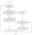
- S810 Obtain a status of a cache of a corresponding channel.
- a rate matching module When the timeslot multiplexing module needs to obtain the code block from the channel #1, a rate matching module first determines a status of a cache of the channel #1.
- S820 Determine whether the status of the cache is empty.
- S830 When the status of the cache is empty (for example, when a bandwidth of service data is less than a timeslot bandwidth allocated to the service data, a cache corresponding to the service data is intermittently empty, indicating that the service data is insufficient to fill the timeslot allocated to the service data), S830 is performed: insert an IDLE code block, and set an MLI in the IDLE code block to 0; and S840 is performed: output the code block.
- S870 is performed: add a value of the MLI in the first code block by 1; and S840 is performed.
- a value of second information in a rate adaptation code block is set, indicating a device that receives the rate adaptation code block to determine whether the rate adaptation code block needs to be processed. For example, when learning that the value of the second information of the rate adaptation code block is 0, the device that receives the rate adaptation code block determines to delete the rate adaptation code block. For another example, when learning that the value of the second information of the rate adaptation code block is not 0, the device that receives the rate adaptation code block determines that the rate adaptation code block does not need to be deleted.
- a procedure of processing the rate adaptation code block by the device that receives the rate adaptation code block is described in detail in a subsequent procedure of deleting a rate adaptation code block by a receiving end device. Details are not described herein.
- S910 Generate a frame structure of an intermediate frame.
- S950 is performed: Determine an identifier of a timeslot corresponding to the payload location, query a timeslot configuration table based on the identifier of the timeslot to obtain an identifier of a channel, and obtain a second code block from the corresponding channel.
- the second code block may be any code block obtained from the channel.
- the channel may be understood as a cache allocated to first service data, and the first service data includes service data corresponding to a code stream that participates in timeslot multiplexing.
- the first service data includes a code block stream obtained by encapsulation processing, and/or a data stream obtained by timeslot multiplexing performed by a previous-hop node.
- a value of second information in an overhead code block is set, indicating a device that receives the overhead code block to determine whether the overhead code block needs to be processed. For example, when learning that the value of the second information of the overhead code block is 0, the device that receives the overhead code block determines to delete the overhead code block. For another example, when learning that the value of the second information of the overhead code block is not 0, the device that receives the overhead code block determines that the overhead code block does not need to be deleted.
- a procedure of processing the overhead code block by the device that receives the overhead code block is described in detail in a subsequent timeslot demultiplexing procedure performed by a receiving end device. Details are not described herein.
- the transmitting end device receives the service data and performs encapsulation, rate matching, and timeslot multiplexing on the service data by code block to obtain the intermediate frame. Further, after obtaining the intermediate frame, the transmitting end device maps the intermediate frame that carries the service data to an OTN frame.
- the transmitting end device maps the intermediate frame that carries the service data to the OTN frame.
- the overhead code block, the data code block, and the rate adaptation code block included in the intermediate frame are encapsulated into a payload area of the OTN frame in a code block-by-code sequence by code block.
- a piece of first frame header location indication information (OPTR) of the intermediate frame is inserted in a first row, columns 15, and 16 in a payload overhead area of the OTN frame to indicate a location of first O code in the OTN frame.
- S440 The transmitting end device sends the OTN frame to the receiving end device, or the receiving end device receives the OTN frame from the transmitting end device.
- the OTN frame is used to carry the intermediate frame that carries service data, and the intermediate frame is obtained in a processing manner of processing the service data performed by code block.
- the foregoing has described in detail the processing manner performed by code block, and details are not described herein again.
- the receiving end device may be the sink processing device in FIG. 5 , or may be the intermediate device (for example, the switching node shown in FIG. 5 ).
- a role played by the receiving end device in the overall service data processing procedure is not limited.
- a device that needs to perform timeslot demultiplexing and rate adaptation code block deletion in the overall service data processing procedure may be understood as the receiving end device.
- the OTN frame received by the receiving end device may be understood as an OTN frame obtained by timeslot multiplexing processing performed by the transmitting end device and the intermediate device.
- the OTN frame received by the receiving end device may be understood as an OTN frame received by the intermediate device from the previous-hop node.
- the receiving end device After receiving the OTN frame, the receiving end device needs to recover the service data.
- S450 The receiving end device obtains the service data from the OTN frame by code block.
- the receiving end device after receiving the OTN frame, the receiving end device needs to perform timeslot demultiplexing, rate adaptation code block deletion, and decapsulation to obtain the service data from the OTN frame.
- the receiving end device After receiving the OTN frame, in a process of obtaining the service data from the OTN frame, the receiving end device ensures that the code block is used as a granularity in different processing procedures (for example, encapsulation, rate matching, and timeslot multiplexing) for obtaining the service data. This reduces complexity of obtaining the service data.
- That the receiving end device performs timeslot demultiplexing by code block after receiving the OTN frame may be understood as follows: A location of the second overhead code block included in the intermediate frame is obtained based on the first frame header location indication information OPTR of the intermediate frame included in the payload overhead area of the OTN frame, mapping relationships between code blocks and services in different code streams are obtained based on a multiplexing identifier MSI in the second overhead code block, and timeslot demultiplexing is performed on a plurality of code streams to obtain a first code stream and at least one second code stream.
- a rate adaptation code block deletion procedure may be separately performed on the different code streams: deleting the rate adaptation code block from the first code stream, and obtaining a data frame corresponding to the service data, where the data frame includes one or more data code blocks corresponding to the service data, the 1 st column of the data frame is a first overhead code block, and the first overhead code block is used to manage the one or more data code blocks.
- the data code blocks corresponding to the service data may be obtained only by deleting the overhead code blocks in the data frames.
- FIG. 10 is a schematic flowchart of timeslot demultiplexing according to an embodiment of this application. The method includes the following steps.
- S1010 Determine a code block in a code stream block by block.
- S1020 Determine whether a fourth code block is an overhead code block.
- the fourth code block may be any code block in the code stream.
- S1030 Determine whether an MLI in the fourth code block is 0.
- S1050 subtract 1 from the MLI in the fourth code block; and S1060 is performed: determine an identifier of a timeslot corresponding to the fourth code block, query a timeslot configuration table, and output the fourth code block to a corresponding subchannel.
- S1010 to S1060 continue to be performed, to complete timeslot demultiplexing.
- the receiving end device may determine, based on a value of second information in an overhead code block, whether to delete the overhead code block, or determine whether to transmit the overhead code block to a next-hop node for processing.
- FIG. 11 is a schematic flowchart of rate adaptation code block deletion according to an embodiment of this application. The method includes the following steps.
- S1110 Determine a code block in a code stream block by block.
- S1120 Determine whether a third code block in the code stream is a rate adaptation code block.
- the third code block may be any code block in the code stream.
- S1150 subtract the MLI in the third code block by 1; and S1160 is performed: output the code block.
- a receiving end device may determine, based on a value of second information in a rate adaptation code block, whether to delete the rate adaptation code block, or determine whether to transmit the rate adaptation code block to a next-hop node for processing.
- the processor 1201 and the memory 1203 may be located in a tributary board, or may be located in a tributary-line integrated board.
- the processor 1201 and the memory 1203 may be located in a tributary board, or may be located in a tributary-line integrated board.
- These computer program instructions may be provided for a general-purpose computer, a dedicated computer, an embedded processor, or a processor of any other programmable data processing device to generate a machine, so that the instructions executed by a computer or a processor of any other programmable data processing device generate an apparatus for implementing a specific function in one or more processes in the flowcharts and/or in one or more blocks in the block diagrams.
- These computer program instructions may also be stored in a computer-readable memory that can instruct the computer or any other programmable data processing device to work in a specific manner, so that the instructions stored in the computer-readable memory generate an artifact that includes an instruction apparatus.
- the instruction apparatus implements a specific function in one or more procedures in the flowcharts and/or in one or more blocks in the block diagrams.
- These computer program instructions may also be loaded onto a computer or another programmable data processing device, so that a series of operations and steps are performed on the computer or the another programmable device, thereby generating computer-implemented processing. Therefore, the instructions executed on the computer or the another programmable device provide steps for implementing a specific function in one or more procedures in the flowcharts and/or in one or more blocks in the block diagrams.
- the processor mentioned in embodiments of this application may be a central processing unit (central processing unit, CPU), and may further be another general-purpose processor, a digital signal processor (digital signal processor, DSP), an application-specific integrated circuit (application-specific integrated circuit, ASIC), a field programmable gate array (field programmable gate array, FPGA) or another programmable logic device, a discrete gate or a transistor logic device, a discrete hardware component, or the like.
- the general-purpose processor may be a microprocessor, or the processor may be any conventional processor or the like.
- the units described as separate parts may or may not be physically separate, and parts displayed as units may or may not be physical units, may be located in one location, or may be distributed on a plurality of network units. A part or all of the units may be selected based on actual requirements to implement the solutions provided in this application.
- All or some of the foregoing embodiments may be implemented by using software, hardware, firmware, or any combination thereof.
- software is used to implement the embodiments, all or a part of the embodiments may be implemented in a form of a computer program product.
- the computer program product includes one or more computer instructions.
- the computer may be a general-purpose computer, a dedicated computer, a computer network, or other programmable apparatuses.
- the computer may be a personal computer, a server, a network device, or the like.
- the computer instructions may be stored in a computer-readable storage medium or may be transmitted from a computer-readable storage medium to another computer-readable storage medium.
- the computer instructions may be transmitted from a website, computer, server, or data center to another website, computer, server, or data center in a wired (for example, a coaxial cable, an optical fiber, or a digital subscriber line (DSL)) or wireless (for example, infrared, radio, and microwave, or the like) manner.
- the computer-readable storage medium may be any usable medium accessible by the computer, or a data storage device, for example, a server or a data center, integrating one or more usable media.
- the usable medium may be a magnetic medium (for example, a floppy disk, a hard disk, or a magnetic tape), an optical medium (for example, a DVD), a semiconductor medium (for example, a solid state disk (solid state disk, SSD)), or the like.
- the usable medium may include but is not limited to any medium that can store program code, for example, a USB flash drive, a removable hard disk, a read-only memory (read-only memory, ROM), a random access memory (random access memory, RAM), a magnetic disk, or an optical disc.
Landscapes
- Engineering & Computer Science (AREA)
- Computer Networks & Wireless Communication (AREA)
- Signal Processing (AREA)
- Time-Division Multiplex Systems (AREA)
Applications Claiming Priority (2)
| Application Number | Priority Date | Filing Date | Title |
|---|---|---|---|
| CN202210598317.4A CN117201968A (zh) | 2022-05-30 | 2022-05-30 | 业务数据处理的方法和装置 |
| PCT/CN2023/094476 WO2023231764A1 (zh) | 2022-05-30 | 2023-05-16 | 业务数据处理的方法和装置 |
Publications (2)
| Publication Number | Publication Date |
|---|---|
| EP4518345A1 true EP4518345A1 (de) | 2025-03-05 |
| EP4518345A4 EP4518345A4 (de) | 2025-09-03 |
Family
ID=88992869
Family Applications (1)
| Application Number | Title | Priority Date | Filing Date |
|---|---|---|---|
| EP23814949.6A Pending EP4518345A4 (de) | 2022-05-30 | 2023-05-16 | Dienstdatenverarbeitungsverfahren und -vorrichtung |
Country Status (4)
| Country | Link |
|---|---|
| US (1) | US20250088301A1 (de) |
| EP (1) | EP4518345A4 (de) |
| CN (1) | CN117201968A (de) |
| WO (1) | WO2023231764A1 (de) |
Family Cites Families (8)
| Publication number | Priority date | Publication date | Assignee | Title |
|---|---|---|---|---|
| CN100590997C (zh) * | 2004-11-02 | 2010-02-17 | 华为技术有限公司 | 一种otn网络中业务复用的开销处理方法 |
| CN106301678B (zh) * | 2015-06-08 | 2020-02-14 | 华为技术有限公司 | 一种数据处理的方法、通信设备及通信系统 |
| CN105099595B (zh) * | 2015-08-04 | 2018-12-25 | 瑞斯康达科技发展股份有限公司 | 一种光传送网otn设备的业务映射方法及装置 |
| CN109478941B (zh) * | 2016-07-22 | 2020-06-26 | 华为技术有限公司 | 一种多路业务传送、接收方法及装置 |
| WO2019153253A1 (zh) * | 2018-02-09 | 2019-08-15 | 华为技术有限公司 | 一种光传送网中业务数据的处理方法及装置 |
| CN112042138B (zh) * | 2018-05-10 | 2022-02-01 | 华为技术有限公司 | 光传送网中低速业务数据的处理方法、装置和系统 |
| CN113395613B (zh) * | 2020-03-11 | 2022-08-19 | 华为技术有限公司 | 一种业务承载的方法、装置和系统 |
| CN113645524A (zh) * | 2020-04-27 | 2021-11-12 | 华为技术有限公司 | 一种业务处理的方法、装置及设备 |
-
2022
- 2022-05-30 CN CN202210598317.4A patent/CN117201968A/zh active Pending
-
2023
- 2023-05-16 EP EP23814949.6A patent/EP4518345A4/de active Pending
- 2023-05-16 WO PCT/CN2023/094476 patent/WO2023231764A1/zh not_active Ceased
-
2024
- 2024-11-27 US US18/962,475 patent/US20250088301A1/en active Pending
Also Published As
| Publication number | Publication date |
|---|---|
| WO2023231764A1 (zh) | 2023-12-07 |
| US20250088301A1 (en) | 2025-03-13 |
| CN117201968A (zh) | 2023-12-08 |
| EP4518345A4 (de) | 2025-09-03 |
Similar Documents
| Publication | Publication Date | Title |
|---|---|---|
| US11967992B2 (en) | Data transmission method and apparatus in optical transport network | |
| US11233571B2 (en) | Method for processing low-rate service data in optical transport network, apparatus, and system | |
| US11082199B2 (en) | Data transmission method in optical network and optical network device | |
| US11234055B2 (en) | Service data processing method and apparatus | |
| US11700083B2 (en) | Method and apparatus for processing service data in optical transport network | |
| EP4099712A1 (de) | Dienstträgerverfahren, vorrichtung und system | |
| US11750314B2 (en) | Service data processing method and apparatus | |
| EP3716641A1 (de) | Verfahren, vorrichtung und system zum datentransport | |
| CN111740782B (zh) | 一种业务数据的处理方法及装置 | |
| US20250286642A1 (en) | Data Transmission Method and Apparatus | |
| US20240322934A1 (en) | Service data processing method and apparatus | |
| US20250080304A1 (en) | Data transmission method and apparatus | |
| EP4518345A1 (de) | Dienstdatenverarbeitungsverfahren und -vorrichtung | |
| CN111989933B (zh) | 光传送网中的数据传输方法及装置 | |
| WO2024109349A1 (zh) | 一种传输数据的方法和装置 | |
| CN117221768B (zh) | 业务数据处理方法和装置 |
Legal Events
| Date | Code | Title | Description |
|---|---|---|---|
| STAA | Information on the status of an ep patent application or granted ep patent |
Free format text: STATUS: THE INTERNATIONAL PUBLICATION HAS BEEN MADE |
|
| PUAI | Public reference made under article 153(3) epc to a published international application that has entered the european phase |
Free format text: ORIGINAL CODE: 0009012 |
|
| STAA | Information on the status of an ep patent application or granted ep patent |
Free format text: STATUS: REQUEST FOR EXAMINATION WAS MADE |
|
| 17P | Request for examination filed |
Effective date: 20241127 |
|
| AK | Designated contracting states |
Kind code of ref document: A1 Designated state(s): AL AT BE BG CH CY CZ DE DK EE ES FI FR GB GR HR HU IE IS IT LI LT LU LV MC ME MK MT NL NO PL PT RO RS SE SI SK SM TR |
|
| A4 | Supplementary search report drawn up and despatched |
Effective date: 20250805 |
|
| DAV | Request for validation of the european patent (deleted) | ||
| DAX | Request for extension of the european patent (deleted) | ||
| RIC1 | Information provided on ipc code assigned before grant |
Ipc: H04Q 11/00 20060101AFI20250730BHEP Ipc: H04J 3/16 20060101ALI20250730BHEP |