EP4518352A1 - Haut-parleur et dispositif électronique - Google Patents
Haut-parleur et dispositif électronique Download PDFInfo
- Publication number
- EP4518352A1 EP4518352A1 EP23830232.7A EP23830232A EP4518352A1 EP 4518352 A1 EP4518352 A1 EP 4518352A1 EP 23830232 A EP23830232 A EP 23830232A EP 4518352 A1 EP4518352 A1 EP 4518352A1
- Authority
- EP
- European Patent Office
- Prior art keywords
- vibration
- coil
- component
- magnetic core
- vibration area
- Prior art date
- Legal status (The legal status is an assumption and is not a legal conclusion. Google has not performed a legal analysis and makes no representation as to the accuracy of the status listed.)
- Pending
Links
Images






Classifications
-
- H—ELECTRICITY
- H04—ELECTRIC COMMUNICATION TECHNIQUE
- H04R—LOUDSPEAKERS, MICROPHONES, GRAMOPHONE PICK-UPS OR LIKE ACOUSTIC ELECTROMECHANICAL TRANSDUCERS; ELECTRIC HEARING AIDS; PUBLIC ADDRESS SYSTEMS
- H04R9/00—Transducers of moving-coil, moving-strip, or moving-wire type
- H04R9/06—Loudspeakers
-
- H—ELECTRICITY
- H04—ELECTRIC COMMUNICATION TECHNIQUE
- H04R—LOUDSPEAKERS, MICROPHONES, GRAMOPHONE PICK-UPS OR LIKE ACOUSTIC ELECTROMECHANICAL TRANSDUCERS; ELECTRIC HEARING AIDS; PUBLIC ADDRESS SYSTEMS
- H04R11/00—Transducers of moving-armature or moving-core type
- H04R11/02—Loudspeakers
-
- H—ELECTRICITY
- H04—ELECTRIC COMMUNICATION TECHNIQUE
- H04R—LOUDSPEAKERS, MICROPHONES, GRAMOPHONE PICK-UPS OR LIKE ACOUSTIC ELECTROMECHANICAL TRANSDUCERS; ELECTRIC HEARING AIDS; PUBLIC ADDRESS SYSTEMS
- H04R9/00—Transducers of moving-coil, moving-strip, or moving-wire type
- H04R9/02—Details
- H04R9/025—Magnetic circuit
-
- H—ELECTRICITY
- H04—ELECTRIC COMMUNICATION TECHNIQUE
- H04R—LOUDSPEAKERS, MICROPHONES, GRAMOPHONE PICK-UPS OR LIKE ACOUSTIC ELECTROMECHANICAL TRANSDUCERS; ELECTRIC HEARING AIDS; PUBLIC ADDRESS SYSTEMS
- H04R2499/00—Aspects covered by H04R or H04S not otherwise provided for in their subgroups
- H04R2499/10—General applications
- H04R2499/11—Transducers incorporated or for use in hand-held devices, e.g. mobile phones, PDA's, camera's
Definitions
- This application relates to the field of acoustic technologies, and in particular, to a speaker and an electronic device.
- a speaker is a transducer that converts an electrical signal into a sound signal, and is widely used in a plurality of different types of electronic devices.
- the speaker may be used in an electronic device such as a notebook computer, a mobile phone, or a headset.
- Performance of the speaker has a great impact on sound quality, and also affects auditory experience of a user.
- There are many parameters used to evaluate the sound quality of the speaker for example, a resonance frequency and low-frequency sensitivity.
- the speaker mainly relies on vibration of a diaphragm to push air to vibrate to produce a sound. When the diaphragm has large stiffness, system stiffness of the speaker is increased. As a result, the speaker has a high resonance frequency and poor low-frequency sensitivity.
- This application provides a speaker and an electronic device that can implement small system stiffness.
- this application provides a speaker, which may include a housing, a diaphragm, a magnet component, and an electromagnetic component.
- the housing has an accommodating cavity, and the diaphragm is disposed in the accommodating cavity and divides the accommodating cavity into two cavities: a front cavity and a rear cavity.
- the diaphragm includes a fastening area and a vibration area.
- the fastening area is fixedly connected to the housing, and the vibration area is configured to be excited to generate vibration, to push surrounding air to produce a sound.
- the vibration area is connected to the fastening area through a folding ear. When the vibration area is excited to generate vibration displacement, the folding ear can provide elastic recovery force, to drive the vibration area to recover to an initial location.
- the initial location of the vibration area is a location at which the vibration displacement of the vibration area is zero.
- the magnet component and the electromagnetic component attract each other through magnetic force.
- the magnet component is fastened in the vibration area, and the electromagnetic component is fastened in the housing.
- acting force applied by the magnet component and the electromagnetic component to the vibration area is zero.
- acting force applied by the magnet component and the electromagnetic component to the vibration area is the same as a vibration displacement direction of the vibration area.
- the vibration displacement direction of the vibration area is a direction in which the initial location of the vibration area points to a vibration location of the vibration area.
- the vibration location of the vibration area may be understood as a location at which the vibration area is located at a moment when the vibration area vibrates. For example, the vibration area vibrates to an upward location that deviates from the initial location.
- the above-mentioned acting force applied by the magnet component and the electromagnetic component to the vibration area does not include acting force used to drive the vibration area to vibrate to produce a sound.
- the acting force does not include force generated when an alternating current is input into the electromagnetic component.
- the electromagnetic component may interact with the magnet component through magnetic field force, to provide negative stiffness for a component of the speaker, thereby reducing system stiffness of the component of the speaker.
- the electromagnetic component may interact with the magnet component through the magnetic field force, to excite the vibration area of the diaphragm to vibrate to produce a sound.
- heat generated by the electromagnetic component may be effectively transferred to the housing, thereby helping improve heat dissipation effect of the electromagnetic component.
- the magnet component may be a permanent magnet.
- the magnet component may include an entire permanent magnet or may include at least two permanent magnets.
- the magnet component may be a ring-shaped permanent magnet, and a pole direction of the magnet component may be consistent with a radial direction of the magnet component, thereby helping improve stability of magnetic force between the magnet component and the electromagnetic component.
- a shape of the magnet component may alternatively be a strip shape, a circular sheet shape, an elliptical ring shape, or the like. Details are not described herein.
- the electromagnetic component may include a coil and a magnetic core.
- the magnetic core may be located in a magnetic circuit of the coil, and is configured to enhance or guide a magnetic field generated by the coil, to ensure acting force between the electromagnetic component and the magnet component.
- a sum of magnetic force between the magnet component and the magnetic core may be zero.
- a sum of magnetic force between the magnet component and the magnetic core in the electromagnetic component may be zero.
- a correction current in the coil there may be a correction current in the coil, and when the vibration area is at the initial location, a sum of magnetic force between the electromagnetic component and the magnet component is zero.
- some components in the speaker may have a manufacturing precision error or an assembly error.
- the vibration displacement of the vibration area is zero, resultant force generated by the magnet component and the magnetic core on the diaphragm is not zero, and consequently the folding ear is elastically deformed.
- a correction current may be input into the electromagnetic component. After the correction current is input into the electromagnetic component, a correction magnetic field can be generated, so that when the vibration displacement of the vibration area is zero, the folding ear is not elastically deformed.
- the speaker may further include a control circuit, and the control circuit may be in signal connection to the electromagnetic component, to effectively control a current in the electromagnetic component.
- the current may be a correction current, may be an alternating current used to enable the diaphragm vibrate to produce a sound, or may be superposition of a correction current and an alternating current.
- the coil may include a first coil and a second coil
- the magnetic core may include a first magnetic core and a second magnetic core
- the first magnetic core may be located in a magnetic circuit of the first coil
- the second magnetic core may be located in a magnetic circuit of the second coil.
- the first coil and the first magnetic core are located in the first vibration displacement direction of the vibration area, and the second coil and the second magnetic core are located in the second vibration displacement direction of the vibration area.
- the first vibration displacement direction is opposite to the second vibration displacement direction.
- the first magnetic core may include a first inner core and a first outer core, the first inner core may be located in an inner ring of the first coil, and the first outer core may be located in an outer ring of the first coil, so that the first magnetic core can effectively enhance or guide a magnetic field generated by the first coil.
- the second magnetic core may include a second inner core and a second outer core, the second inner core may be located in an inner ring of the second coil, and the second outer core may be located in an outer ring of the second coil, so that the second magnetic core can effectively enhance or guide a magnetic field generated by the second coil.
- the coil and the magnetic core may be located on a same plane, and the plane is parallel to the diaphragm, so that space occupation (that is, a height size) of the coil and the magnetic core in a vibration displacement direction of the vibrated vibration area can be effectively reduced, thereby helping reduce a height size of the entire speaker.
- the magnet component may be fastened in the vibration area, and the electromagnetic component may be fastened in the housing.
- the magnetic core may include a first magnetic core and a second magnetic core
- the coil may include a first coil, a second coil, a third coil, and a fourth coil.
- the first magnetic core may be U-shaped, and the first coil and the second coil are respectively wound on two opposite cantilevers of the first magnetic core.
- the second magnetic core may be U-shaped, and the third coil and the fourth coil are respectively wound on two opposite cantilevers of the second magnetic core.
- the first magnetic core is located on a first side edge of the diaphragm, and the second magnetic core is located on a second side edge of the diaphragm. The first side edge and the second side edge are away from each other, and U-shaped openings of the first magnetic core and the second magnetic core are disposed opposite to each other, thereby helping reduce a height size of the speaker.
- projections of the first coil, the second coil, the third coil, and the fourth coil on a plane on which the diaphragm is located do not overlap the diaphragm. This helps ensure maximum vibration displacement of the diaphragm, and also helps effectively reduce a height size of the speaker.
- locations of the magnet component and the electromagnetic component may be interchanged.
- another speaker provided in this application may include a housing, a diaphragm, a magnet component, and an electromagnetic component.
- the housing has an accommodating cavity, and the diaphragm is disposed in the accommodating cavity and divides the accommodating cavity into two cavities: a front cavity and a rear cavity.
- the diaphragm includes a fastening area and a vibration area.
- the fastening area is fixedly connected to the housing, and the vibration area is configured to be excited to generate vibration, to push surrounding air to produce a sound.
- the vibration area is connected to the fastening area through a folding ear. When the vibration area is excited to generate vibration displacement, the folding ear can provide elastic recovery force, to drive the vibration area to recover to an initial location.
- the initial location of the vibration area is a location at which the vibration displacement of the vibration area is zero.
- the magnet component and the electromagnetic component attract each other through magnetic force.
- the electromagnetic component is fastened in the vibration area, and the magnet component is fastened in the housing.
- acting force applied by the magnet component and the electromagnetic component to the vibration area is zero.
- acting force applied by the magnet component and the electromagnetic component to the vibration area is the same as a vibration displacement direction of the vibration area.
- the vibration displacement direction of the vibration area is a direction in which the initial location of the vibration area points to a vibration location of the vibration area.
- the vibration location of the vibration area may be understood as a location at which the vibration area is located at a moment when the vibration area vibrates. For example, the vibration area vibrates to an upward location that deviates from the initial location.
- the above-mentioned acting force applied by the magnet component and the electromagnetic component to the vibration area does not include acting force used to drive the vibration area to vibrate to produce a sound.
- the acting force does not include force generated when an alternating current is input into the electromagnetic component.
- the electromagnetic component may interact with the magnet component through magnetic field force, to provide negative stiffness for a component of the speaker, thereby reducing system stiffness of the component of the speaker.
- the electromagnetic component may interact with the magnet component through the magnetic field force, to excite the vibration area of the diaphragm to vibrate to produce a sound.
- the magnet component may be a permanent magnet.
- the magnet component may include an entire permanent magnet or may include at least two permanent magnets.
- the magnet component may be a ring-shaped permanent magnet, and a pole direction of the magnet component may be consistent with a radial direction of the magnet component, thereby helping improve stability of magnetic force between the magnet component and the electromagnetic component.
- a shape of the magnet component may alternatively be a strip shape, a circular sheet shape, an elliptical ring shape, or the like. Details are not described herein.
- the electromagnetic component may include a coil and a magnetic core.
- the magnetic core may be located in a magnetic circuit of the coil, and is configured to enhance or guide a magnetic field generated by the coil, to ensure acting force between the electromagnetic component and the magnet component.
- a sum of magnetic force between the magnet component and the magnetic core may be zero.
- a sum of magnetic force between the magnet component and the magnetic core in the electromagnetic component may be zero.
- a correction current in the coil there may be a correction current in the coil, and when the vibration area is at the initial location, a sum of magnetic force between the electromagnetic component and the magnet component is zero.
- some components in the speaker may have a manufacturing precision error or an assembly error.
- the vibration displacement of the vibration area is zero, resultant force generated by the magnet component and the magnetic core on the diaphragm is not zero, and consequently the folding ear is elastically deformed.
- a correction current may be input into the electromagnetic component. After the correction current is input into the electromagnetic component, a correction magnetic field can be generated, so that when the vibration displacement of the vibration area is zero, the folding ear is not elastically deformed.
- the speaker may further include a control circuit, and the control circuit may be in signal connection to the electromagnetic component, to effectively control a current in the electromagnetic component.
- the current may be a correction current, may be an alternating current used to enable the diaphragm vibrate to produce a sound, or may be superposition of a correction current and an alternating current.
- the magnet component may include a first permanent magnet and a second permanent magnet, the first permanent magnet is located in the first vibration displacement direction of the vibration area, and the second permanent magnet is located in the second vibration displacement direction of the vibration area.
- the first vibration displacement direction is opposite to the second vibration displacement direction.
- the coil and the magnetic core may be located on a same plane, and the plane is parallel to the diaphragm, so that space occupation (that is, a height size) of the coil and the magnetic core in a vibration displacement direction of the vibrated vibration area can be effectively reduced, thereby helping reduce a height size of the entire speaker.
- disposing locations of the magnet component and the electromagnetic component may be adaptively adjusted based on different requirements, and therefore there is good flexibility.
- this application further provides an electronic device, which may include a controller and any one of the foregoing speakers.
- the controller may be in signal connection to the electromagnetic component in the speaker, to effectively control a current that is input into the electromagnetic component.
- the electronic device may be a mobile phone, a tablet computer, a sound box, a headset, or the like.
- a specific type of the electronic device is not limited in this application.
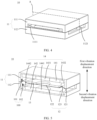
- FIG. 1 is a diagram of a three-dimensional structure of a mobile phone.
- the speaker may be used in the mobile phone. Specifically, the speaker may be disposed at a location such as a top of the mobile phone or a bottom of the mobile phone.
- the speaker may alternatively be used in an electronic device such as a tablet computer, a sound box, a headset, or a television.
- a specific application scenario of the speaker is not limited in this application.
- a speaker is an electro-acoustic transducer that can convert an electrical signal into a sound signal for playing.
- FIG. 2 shows an audio signal processing process
- An analog signal (for example, a human voice or a natural sound wave) may be recorded by using an input device (for example, a microphone), and the analog signal is converted into an electrical signal by using an audio adapter 1. Finally, the electrical signal may be stored in a storage device as an audio file.
- the electrical signal may be converted into an analog signal by using an audio adapter 2, and converted into an analog signal by using an output device (for example, a speaker) for playing.
- speakers when distinguishing is performed based on different driving force, speakers may be classified into a moving coil type, a moving iron type, a piezoelectric type, an electrostatic type, and the like.
- sound production principles of different types of speakers all are producing a sound by pushing nearby air to vibrate through diaphragm vibration.
- FIG. 3 is a sectional view of a partial structure of a moving coil speaker 01.
- the speaker 01 may include a diaphragm 011, a coil 012, and a permanent magnet 013.
- the diaphragm 011 has a folding ear 014, and the folding ear 014 divides the diaphragm into an edge area 015 for fastening and a middle area 016 for vibration.
- the edge area 015 of the diaphragm 011 is usually fixedly connected to a housing (not shown in FIG. 3 ) of the speaker 01, and the coil 012 is fastened on a surface of the middle area 016.
- the coil 012 is located in a magnetic gap 017 of the permanent magnet 013. When an alternating current is input into the coil 012, under action of Lorentz force, the coil 012 drives the middle area 016 of the diaphragm 011 to vibrate to produce a sound.
- a vibration component such as the middle area 016 of the diaphragm 011 may be referred to as a vibration system, and the folding ear 014, the edge area 015, and the like may be referred to as support systems.
- the support system such as the folding ear 014 generates elastic recovery force for the middle area 016.
- the elastic recovery force varies with vibration displacement of the middle area 016, and system stiffness Kms of the speaker 01 may be obtained.
- the vibration mass Mms and the system stiffness Kms determine a first-order resonance frequency of the vibration system of the speaker 01.
- the system stiffness Kms of the speaker 01 mainly includes two aspects.
- One aspect is a size of a rear cavity of the speaker, that is, air stiffness Kb.
- a larger rear cavity indicates lower air stiffness Kb, and on the contrary, a smaller rear cavity indicates higher air stiffness Kb.
- the other aspect is stiffness Ks of the folding ear 014 or another support system, and the stiffness is related to a Young's modulus, a thickness, and a structural design of a material of the folding ear 014.
- the support system such as the folding ear 014 generates the elastic recovery force for the middle area 016, and the elastic recovery force varies with the vibration displacement of the middle area 016. Therefore, theoretically, the system stiffness Kms can be reduced by introducing force that offsets the recovery force, thereby reducing the first-order resonance frequency fs.
- K represents new system stiffness
- Kb represents introduced negative stiffness
- a mechanism that can generate negative stiffness is introduced, so that system stiffness of the speaker can be effectively reduced, thereby helping reduce a resonance frequency of the speaker, improve low-frequency sensitivity, and so on.
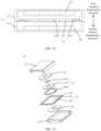
- a speaker 10 may include a housing 11, a diaphragm 12, a magnet component 13, and an electromagnetic component 14.
- the magnet component 13 and the electromagnetic component 14 may be understood as introduced mechanisms that can generate negative stiffness.
- a magnetic field for interaction between the magnet component 13 and the electromagnetic component 14 can further excite the diaphragm 12 to vibrate to produce a sound.
- the housing 11 has an accommodating cavity 100, and the diaphragm 12 is disposed in the accommodating cavity 100 and divides the accommodating cavity 100 into two cavities: a front cavity 101 and a rear cavity 102.
- the diaphragm 12 includes a fastening area 121 and a vibration area 122.
- the fastening area 121 is fixedly connected to the housing 11, and the vibration area 122 is configured to be excited to generate vibration, to push surrounding air to produce a sound.
- the vibration area 122 is connected to the fastening area 121 through a folding ear 123.
- the folding ear 123 can provide elastic recovery force, to drive the vibration area 122 to recover to an initial location.
- the initial location of the vibration area 122 is a location at which the vibration displacement of the vibration area 122 is zero.
- the magnet component 13 and the electromagnetic component 14 attract each other through magnetic force.
- the magnet component 13 is fastened in the vibration area 122, and the electromagnetic component 14 is fastened in the housing 11.
- the vibration displacement direction of the vibration area 122 is a direction in which the initial location of the vibration area 122 points to a vibration location of the vibration area 122.
- the vibration location of the vibration area may be understood as a location at which the vibration area is located at a moment when the vibration area vibrates. For example, the vibration area vibrates to an upward location that deviates from the initial location.
- the vibration area 122 may generate vibration displacement in a first vibration displacement direction or a second vibration displacement direction.
- the vibration displacement of the vibration area 122 is zero
- the folding ear 123 is not elastically deformed. Therefore, the folding ear 123 does not generate recovery force for the vibration area 122.
- magnetic force generated by the electromagnetic component 14 for the magnet component 13 is zero. Therefore, external force generated by the electromagnetic component 14 and the magnet component 13 for the vibration area 122 is zero.
- the folding ear 123 After the vibration area 122 has displacement in the first vibration displacement direction, the folding ear 123 generates recovery force in the second vibration displacement direction for the vibration area 122, to drive the vibration area 122 to recover to a location at which the vibration displacement is zero.
- the electromagnetic component 14 generates magnetic force in the first vibration displacement direction for the magnet component 13, to drive the vibration area 122 to generate displacement in the first vibration displacement direction, so that a part of the recovery force generated by the folding ear 123 can be offset, thereby reducing system stiffness of the speaker 10.
- a direction of resultant force applied by the electromagnetic component 14 and the magnet component 13 is always the same as a direction in which the vibration area 122 leaves the initial location, or the direction of the resultant force applied by the electromagnetic component 14 and the magnet component 13 is always opposite to a direction in which the vibration area 122 faces the initial location, and the resultant force can offset a part of the recovery force generated by the folding ear 123, thereby reducing system stiffness of the speaker 10.
- an alternating current may be input into the electromagnetic component 14, so that the electromagnetic component 14 generates an alternating magnetic field.
- a magnetic field of the magnet component 13 interacts with the alternating magnetic field generated by the electromagnetic component 14, so that the vibration area 122 is excited to generate vibration.
- the electromagnetic component 14 may interact with the magnet component 13 through magnetic field force, to provide negative stiffness for a component of the speaker 10, thereby reducing system stiffness of the component of the speaker 10.
- the electromagnetic component 14 may interact with the magnet component 13 through the magnetic field force, to excite the vibration area 122 of the diaphragm 12 to vibrate to produce a sound.
- heat generated by the electromagnetic component 14 may be effectively transferred to the housing 11, thereby helping improve heat dissipation effect of the electromagnetic component 14.
- an embodiment of this application further provides a diagram of comparison between frequency responses of different speakers.
- a horizontal coordinate is a frequency in units of Hz
- a vertical coordinate is a sound pressure value in units of dB.
- a solid line represents a frequency response curve of a conventional speaker
- a dashed line represents a frequency response curve of the speaker provided in this embodiment of this application. It can be clearly learned from comparison that, the speaker provided in this embodiment of this application has a lower resonance frequency and better low-frequency sensitivity.
- the magnet component 13 and the electromagnetic component 14 magnetically attract each other means the following: When a direct current or an alternating current is input into the electromagnetic component 14, acting force for mutual magnetic attraction exists between the magnet component 13 and the electromagnetic component 14; or when no current or an alternating current is input into the electromagnetic component 14, acting force for mutual magnetic attraction exists between the magnet component 13 and the electromagnetic component 14. Specifically, when no current is input or a direct current is input, the magnet component 13 and the electromagnetic component 14 may generate magnetic attraction force; and when an alternating current is input, in addition to the magnetic attraction force, force that enables the diaphragm 12 to vibrate can be further generated, to produce a sound.
- the magnet component 13 may be a permanent magnet
- the electromagnetic component 14 may include a coil and a magnetic core.
- the magnetic core can be attracted by the permanent magnet. Therefore, when no current is input into the coil, magnetic attraction force exists between the permanent magnet and the magnetic core. After a current is input into the coil, a magnetic field attracted to the magnet component 13 is generated.
- the magnetic core may be located in a magnetic circuit of the coil, and is configured to enhance or guide the magnetic field.
- the magnetic circuit of the coil may be understood as an area in which magnetic induction lines are dense in the magnetic field generated by the coil.
- the magnetic core has good magnetic permeability, which can increase magnetic induction intensity and magnetic flux density of the coil, so that the electromagnetic component 14 can generate large magnetic force.
- the magnetic core may be formed by sintering a plurality of iron oxide mixtures. A specific material of the magnetic core is not limited in this application.
- the speaker 10 may have various structure types.
- the housing 11 when the housing 11 is disposed, appearance of the housing 11 is approximately in a shape of a rectangular block.
- the housing 11 may include an upper cover 111 and a lower cover 112 that are mutually buckled.
- the diaphragm 12 is fastened between the upper cover 111 and the lower cover 112.
- shape contours of an edge of the upper cover 111, an edge of the lower cover 112, and the fastening area 121 of the diaphragm 12 are approximately the same.
- the fastening area 121 is fastened between the upper cover 111 and the lower cover 112 through clamping.
- a side wall of the upper cover 111 has a notch 1111, and a side wall of the lower cover 112 has a notch 1121.
- the notch 1111 may be used as a sound output hole of the speaker 10
- the notch 1121 may be used as a ventilation hole of the rear cavity.
- the housing 11 may alternatively be of another shape structure. This is not limited in this application.
- At least some areas of the housing 11 may be made of a magnetic material, so that a magnetic field generated by the electromagnetic component 14 can be effectively enhanced or guided.
- an area in which the electromagnetic component 14 is vertically projected onto the housing 11 may be made of a magnetic material.
- Another area of the housing 11 may be made of a material such as plastic or metal.
- the entire housing 11 may be made of a magnetic material.
- the electromagnetic component 14 when the electromagnetic component 14 is disposed, the electromagnetic component 14 includes two coils and two magnetic cores. Specifically, the two coils are respectively a first coil 141 and a second coil 142, and the two magnetic cores are respectively a first magnetic core 143 and a second magnetic core 144.
- the first magnetic core 143 is located in a magnetic circuit of the first coil 141
- the second magnetic core 144 is located in a magnetic circuit of the second coil 142.
- the first coil 141 and the first magnetic core 143 are located in the first vibration displacement direction of the vibration area 122.
- the second coil 142 and the second magnetic core 144 are located in the second vibration displacement direction of the vibration area 122.
- the first coil 141 and the second coil 142 are disposed symmetrically around the magnet component 13
- the first magnetic core 143 and the second magnetic core 144 are disposed symmetrically around the magnet component 13.
- F1 increases, and F2 decreases, that is, a direction of the resultant force of F1 and F2 is consistent with the first vibration displacement direction.
- the magnet component 13 generates displacement towards the second vibration displacement direction, so that F1 decreases, and F2 increases, that is, the direction of the resultant force of F1 and F2 is consistent with the second vibration displacement direction.
- a sum of magnetic force generated by the electromagnetic component 14 for the magnet component 13 is zero; and when the vibration displacement of the vibration area 122 is not zero, a direction of the magnetic force generated by the electromagnetic component 14 for the magnet component 13 is consistent with a vibration displacement direction of the vibration area 122.
- larger vibration displacement of the vibration area 122 indicates larger magnetic force generated by the electromagnetic component 14 for the magnet component 13.
- an embodiment of this application further provides a data diagram illustrating that resultant force of F1 and F2 varies with vibration displacement of the vibration area 122.
- a horizontal coordinate represents the vibration displacement of the vibration area 122, and the vibration displacement is in units of mm.
- a vertical coordinate represents electromagnetic force generated by the electromagnetic component 14 for the magnet component 13, and the electromagnetic force is in units of N.
- the electromagnetic force When the electromagnetic force is greater than zero, it indicates that a direction of the resultant force of F1 and F2 is consistent with the first vibration displacement direction; and when the electromagnetic force is less than zero, it indicates that the direction of the resultant force of F1 and F2 is consistent with the second vibration displacement direction.
- FIG. 9 further provides a data diagram illustrating that negative stiffness of the electromagnetic component 14 and the magnet component 13 varies with vibration displacement of the vibration area 122.
- a horizontal coordinate represents the vibration displacement of the vibration area 122, and the vibration displacement is in units of mm.
- a vertical coordinate represents the negative stiffness provided by the electromagnetic component 14 and the magnet component 13, and the negative stiffness is in units of N/mm.
- an embodiment of this application further provides a data diagram illustrating that force applied to the vibration area 122 varies with vibration displacement.
- a horizontal coordinate represents the vibration displacement of the vibration area 122, and the vibration displacement is in units of mm.
- a vertical coordinate represents the force applied to the vibration area 122, and the force is in units of N.
- S1 represents a data curve illustrating that recovery force applied by the folding ear 123 on the vibration area 122 varies with vibration displacement.
- S2 represents a data curve illustrating that magnetic attraction force applied by the electromagnetic component 14 and the magnetic attraction component to the vibration area 122 varies with vibration displacement. In this case, a current is input into neither the first coil 141 nor the second coil 142 in the electromagnetic component 14.
- the recovery force generated by the folding ear 123 increases as the vibration displacement of the vibration area 122 increases, and the magnetic attraction force between the electromagnetic component 14 and the magnet component 13 increases as the vibration displacement of the vibration area 122 increases.
- the magnetic attraction force between the electromagnetic component 14 and the magnet component 13 is less than the recovery force generated by the folding ear 123.
- a correction current may alternatively be input into the electromagnetic component 14, and may be used to adjust magnetic field force between the electromagnetic component 14 and the magnet component 13.
- some components in the speaker 10 may have a manufacturing precision error or an assembly error.
- a correction current may be input into the electromagnetic component 14.
- the correction current may be a direct current. After the correction current is input into the electromagnetic component 14, a correction magnetic field can be generated.
- S3 in FIG. 10 represents a data curve illustrating that magnetic attraction force applied by the electromagnetic component 14 and the magnet component 13 to the vibration area 122 varies with vibration displacement after a direct current of 0.5 ampere is input into both the first coil 141 and the second coil 142 in the electromagnetic component 14, and S4 represents a data curve illustrating that magnetic attraction force applied by the electromagnetic component 14 and the magnet component 13 to the vibration area 122 varies with vibration displacement after a direct current of -0.5 ampere is input into the first coil 141 and the second coil 142 in the electromagnetic component 14.
- a correction current may be input into the electromagnetic component 14, to adjust magnetic force between the electromagnetic component 14 and the magnet component 13.
- the vibration displacement of the vibration area 122 is zero, the folding ear 123 is not elastically deformed, to ensure that when the diaphragm 12 is excited to generate vibration, recovery force provided by the folding ear 123 in the first vibration displacement direction is consistent with that provided in the second vibration displacement direction.
- a correction current may alternatively be input only into the first coil 141, or a correction current may be input only into the second coil 142. Details are not described herein.
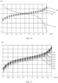
- FIG. 11 further provides a data diagram illustrating that measured acting force applied by the electromagnetic component 14 and the magnet component 13 to the vibration area 122 varies with vibration displacement of the vibration area 122 in a case of different input power of the electromagnetic component 14.
- a horizontal coordinate represents the vibration displacement of the vibration area 122, and the vibration displacement is in units of mm. When the vibration displacement is greater than zero, it indicates that the vibration area 122 generates vibration displacement towards the first vibration displacement direction; and when the vibration displacement is less than zero, it indicates that the vibration area 122 generates vibration displacement towards the second vibration displacement direction.
- a vertical coordinate represents the magnetic attraction force applied by the electromagnetic component 14 and the magnetic attraction component to the vibration area 122, and the magnetic attraction force is in units of N.
- S10 represents a data curve illustrating that magnetic attraction force applied by the electromagnetic component 14 and the magnetic attraction component to the vibration area 122 varies with vibration displacement when input power of the electromagnetic component is zero.
- S11 represents a data curve illustrating that magnetic attraction force applied by the electromagnetic component 14 and the magnetic attraction component to the vibration area 122 varies with vibration displacement when input power of the electromagnetic component is 1 watt (W).
- S12 represents a data curve illustrating that magnetic attraction force applied by the electromagnetic component 14 and the magnetic attraction component to the vibration area 122 varies with vibration displacement when input power of the electromagnetic component is 2 watts (W).
- S13 represents a data curve illustrating that magnetic attraction force applied by the electromagnetic component 14 and the magnetic attraction component to the vibration area 122 varies with vibration displacement when input power of the electromagnetic component is 3 watts (W).
- S15 represents a data curve illustrating that magnetic attraction force applied by the electromagnetic component 14 and the magnetic attraction component to the vibration area 122 varies with vibration displacement when input power of the electromagnetic component is 5 watts (W).
- S16 represents a data curve illustrating that magnetic attraction force applied by the electromagnetic component 14 and the magnetic attraction component to the vibration area 122 varies with vibration displacement when input power of the electromagnetic component is 6 watts (W).
- S17 represents a data curve illustrating that magnetic attraction force applied by the electromagnetic component 14 and the magnetic attraction component to the vibration area 122 varies with vibration displacement when input power of the electromagnetic component is 7 watts (W).
- a specific magnitude of the correction current may be set before delivery of the speaker 10.
- a manufacturer may perform force detection or debugging on the magnet component 13 or the folding ear 123, to ensure that magnetic force between the electromagnetic component 14 and the magnet component 13 is zero (or the folding ear 123 is not elastically deformed).
- a detection device may be disposed in the speaker 10. During use (after delivery) of the speaker 10, force detection may be performed on a component such as the folding ear 123, to ensure that magnetic force between the electromagnetic component 14 and the magnet component 13 is zero.
- a specific type and a detection manner of the detection device may be properly set based on an actual requirement. This is not limited in this application.
- the first magnetic core 143 and the first coil 141 may be in various shapes.
- the first magnetic core 143 includes a first inner core 1431 and a first outer core 1432.
- the first inner core 1431 is located in an inner ring of the first coil 141
- the first outer core 1432 is located in an outer ring of the first coil 141.
- a structure including the first coil 141, the first inner core 1431, and the first outer core 1432 can generate a large magnetic field.
- the first coil 141 is of a circular ring-shaped structure
- the first inner core 1431 is in a circular sheet shape
- the first outer core 1432 is in a circular ring shape.
- There is a small gap between the first coil 141 and each of the first inner core 1431 and the first outer core 1432 so that structures of the first coil 141, the first inner core 1431, and the first outer core 1432 are compact, thereby reducing space occupation.
- the first coil 141 may be an elliptical ring
- the first inner core 1431 may be an elliptical sheet
- the first outer core 1432 may be in a shape such as an elliptical ring. Specific shapes of the first coil 141, the first inner core 1431, and the first outer core 1432 are not limited in this application.
- disposing of the first inner core 1431 or the first outer core 1432 may alternatively be omitted. Details are not described herein.
- the second magnetic core 144 may include a second inner core 1441 and a second outer core 1442, the second inner core 1441 may be located in an inner ring of the second coil 142, and the second outer core 1442 is located in an outer ring of the second coil 142.
- first coil 141 and the second coil 142 may be the same or approximately the same, and the second magnetic core 144 and the first magnetic core 143 may be the same or approximately the same. Details are not described herein.
- the coil and the magnetic core when the coil and the magnetic core are specifically disposed, the coil and the magnetic core may be located on a same plane, and the plane may be parallel to the diaphragm, so that a height size of a structure including the coil and the magnetic core can be effectively reduced, thereby helping reducing a height size of the entire speaker 10.
- the first coil 141 and the first magnetic core 143 are used as an example.
- the first coil 141 and the first magnetic core 143 are located on a same plane.
- the same plane is an approximate plane, and the plane may have a specific thickness. This specifically means that in a direction perpendicular to the plane, the first coil 141 and the first magnetic core 143 do not have an obvious protruding structure or a large size.
- a height size of a structure including the first coil 141 and the first magnetic core 143 is small, so that space occupation in a vibration displacement direction of the vibration area 122 can be reduced, thereby helping reduce the height size of the speaker 10.
- the height size of the speaker 10 can be effectively reduced.
- the magnet component 13 may be a permanent magnet.
- the magnet component 13 is a circular ring-shaped permanent magnet.
- a pole direction of the magnet component 13 is consistent with a radial direction.
- an N pole of the magnet component 13 may be located in an inner ring of a circular ring shape, and an S pole is located in an outer ring; or the N pole is located in the inner ring, and the S pole is located in the inner ring.
- the N pole of the magnet component 13 is located in the outer ring, and the S pole is located in the inner ring.
- FIG. 12 After a current is input into the first coil 141 and the second coil 142, a pole direction of a structure including the first coil 141, the first inner core 1431, and the first outer core 1432 is shown in FIG. 12 , to be specific, the S pole is located at the first inner core 1431, and the N pole is located at the first outer core 1432.
- a pole direction of a structure including the second coil 142, the second inner core 1441, and the second outer core 1442 is shown in FIG. 12 , to be specific, the N pole is located at the first inner core 1431, and the S pole is located at the first outer core 1432. It can be learned from “like poles repel each other and unlike poles attract each other", in this case, magnetic field force applied to the magnet component 13 faces the second coil 142.
- a shape of the magnet component 13 may alternatively be a strip shape, a circular sheet shape, an elliptical ring shape, or the like. Details are not described herein.
- the magnet component 13 may be one permanent magnet, or may include a plurality of permanent magnets.
- the magnet component 13 may include two permanent magnets, and the two permanent magnets are respectively a permanent magnet a and a permanent magnet b.
- the permanent magnet a and the permanent magnet b each are in a semi-circular ring shape, and the permanent magnet a and the permanent magnet b may form a circular ring shape.
- the permanent magnet a and the permanent magnet b may be fixedly connected in a manner such as bonding.
- the magnet component 13 may include three or more permanent magnets.
- a quantity of permanent magnets and a shape of the permanent magnet are not limited in this application.
- the magnet component 13 may be fastened on a surface of the vibration area 122, and the electromagnetic component 14 may be fastened in the housing 11.
- locations of the magnet component 13 and the electromagnetic component 14 may alternatively be interchanged.
- the electromagnetic component 14 may be fastened on the surface of the vibration area 122, and the magnet component may be fastened in the housing 11, to help reduce a height size (that is, a size in a vibration displacement direction parallel to the vibration area 122) of a structure including the electromagnetic component 14 and the diaphragm 12.
- the magnetic field generated by the electromagnetic component 14 not only can cover the diaphragm 12, but also can store effective magnetic field strength in the first vibration displacement direction or the second vibration displacement direction, thereby helping reduce a height size of the electromagnetic component 14.
- the coil 145 in the electromagnetic component 14 is not disposed on a surface of the diaphragm 12, the coil 145 needs to extend into a magnetic gap of the magnet component (for example, a first permanent magnet 131 in FIG. 14 ), and the coil 145 needs to be always in the magnetic gap in an amplitude range of the vibration area 122. If the coil 145 is not in the magnetic gap, Lorentz force between the coil 145 and the first permanent magnet 131 fails, and the vibration area 122 cannot be effectively driven to vibrate to produce a sound. Therefore, the electromagnetic component 14 is fastened on the surface of the vibration area 122, and the magnet component is fastened in the housing 11, thereby helping reduce the height size of the structure including the electromagnetic component 14 and the diaphragm 12.
- the magnet component 13 may include the first permanent magnet 131 and a second permanent magnet 132.
- the first permanent magnet 131 is located in the first vibration displacement direction of the vibration area 122
- the second permanent magnet 132 is located in the second vibration displacement direction of the vibration area 122.
- the electromagnetic component 14 includes the coil 145 and a magnetic core 146 disposed in a magnetic circuit of the coil 145.
- the magnetic core 146 includes an inner core 1461 and an outer core 1462.
- the inner core 1461 is located in an inner ring of the coil 145
- the outer core 1462 is located in an outer ring of the coil 145.
- the magnetic core may include a first magnetic core 143 and a second magnetic core 144, and the coil includes a first coil 141, a second coil 142, a third coil 147, and a fourth coil 148.
- the magnet component 13 is a ring-shaped permanent magnet
- the first magnetic core 143 is U-shaped
- the first coil 141 and the second coil 142 are respectively wound on two opposite cantilevers of the first magnetic core 143.
- the second magnetic core 144 is U-shaped, and the third coil 147 and the fourth coil 148 are respectively wound on two opposite cantilevers of the second magnetic core 144.
- the first magnetic core 143 is located on a first side edge (for example, a left side in FIG. 16 ) of the diaphragm 12
- the second magnetic core 144 is located on a second side edge (for example, a right side in FIG. 16 ) of the diaphragm 12.
- the first side edge and the second side edge are away from each other, and U-shaped openings of the first magnetic core 143 and the second magnetic core 144 are disposed opposite to each other, thereby helping reduce a height size of the speaker 10.
- first coil 141, the second coil 142, the third coil 147, and the fourth coil 148 on a plane on which the diaphragm 12 is located do not overlap the diaphragm 12, thereby helping ensure maximum vibration displacement of the diaphragm 12.
- the first coil 141, the second coil 142, the third coil 147, and the fourth coil 148 do not occupy vibration displacement space of the vibration area 122. Therefore, a distance between the two opposite cantilevers of the first magnetic core 143 may be set to be small, and correspondingly, a distance between the two opposite cantilevers of the second magnetic core 144 may be set to be small, thereby helping reduce the height size of the speaker 10.
- an embodiment of this application further provides a data diagram illustrating that acting force applied by the electromagnetic component 14 and the magnet component 13 to the vibration area 122 varies with vibration displacement of the vibration area 122.
- a horizontal coordinate represents the vibration displacement of the vibration area 122, and the vibration displacement is in units of mm.
- a vertical coordinate represents the magnetic attraction force applied by the electromagnetic component 14 and the magnetic attraction component to the vibration area 122, and the magnetic attraction force is in units of N.
- S5 represents a data curve illustrating that magnetic attraction force applied by the electromagnetic component 14 and the magnetic attraction component to the vibration area 122 varies with vibration displacement. In this case, no current is input into the electromagnetic component 14.
- S6 represents a data curve illustrating that magnetic attraction force applied by the electromagnetic component 14 and the magnetic attraction component to the vibration area 122 varies with vibration displacement after a direct current of 1.4 ampere is input into the electromagnetic component 14
- S7 represents a data curve illustrating that magnetic attraction force applied by the electromagnetic component 14 and the magnetic attraction component to the vibration area 122 varies with vibration displacement after a direct current of -1.4 ampere is input into the electromagnetic component 14.
- the speaker 10 may further include a control circuit, and the control circuit is in signal connection to the electromagnetic component 14, to effectively control a current in the electromagnetic component 14.
- the current may be a correction current, may be an alternating current used to enable the diaphragm 12 vibrate to produce a sound, or may be superposition of a correction current and an alternating current.
- a controller 20 in the electronic device may be in signal connection to the electromagnetic component 14, to effectively control a current that is input into the electromagnetic component 14. Details are not described herein.
Landscapes
- Physics & Mathematics (AREA)
- Engineering & Computer Science (AREA)
- Acoustics & Sound (AREA)
- Signal Processing (AREA)
- Electromagnetism (AREA)
- Audible-Bandwidth Dynamoelectric Transducers Other Than Pickups (AREA)
- Obtaining Desirable Characteristics In Audible-Bandwidth Transducers (AREA)
Applications Claiming Priority (2)
| Application Number | Priority Date | Filing Date | Title |
|---|---|---|---|
| CN202210770809.7A CN117376785A (zh) | 2022-06-30 | 2022-06-30 | 一种扬声器和电子设备 |
| PCT/CN2023/102698 WO2024002055A1 (fr) | 2022-06-30 | 2023-06-27 | Haut-parleur et dispositif électronique |
Publications (2)
| Publication Number | Publication Date |
|---|---|
| EP4518352A1 true EP4518352A1 (fr) | 2025-03-05 |
| EP4518352A4 EP4518352A4 (fr) | 2025-08-20 |
Family
ID=89382981
Family Applications (1)
| Application Number | Title | Priority Date | Filing Date |
|---|---|---|---|
| EP23830232.7A Pending EP4518352A4 (fr) | 2022-06-30 | 2023-06-27 | Haut-parleur et dispositif électronique |
Country Status (4)
| Country | Link |
|---|---|
| US (1) | US20260122427A1 (fr) |
| EP (1) | EP4518352A4 (fr) |
| CN (1) | CN117376785A (fr) |
| WO (1) | WO2024002055A1 (fr) |
Families Citing this family (1)
| Publication number | Priority date | Publication date | Assignee | Title |
|---|---|---|---|---|
| WO2026020344A1 (fr) * | 2024-07-24 | 2026-01-29 | 瑞声光电科技(常州)有限公司 | Haut-parleur |
Family Cites Families (8)
| Publication number | Priority date | Publication date | Assignee | Title |
|---|---|---|---|---|
| US6574346B1 (en) * | 1999-04-26 | 2003-06-03 | Matsushita Electric Industrial Co., Ltd. | Bass reproduction speaker apparatus |
| JP3598014B2 (ja) * | 1999-04-26 | 2004-12-08 | 松下電器産業株式会社 | 低音再生スピーカ装置 |
| JP2005027286A (ja) * | 2003-06-10 | 2005-01-27 | Matsushita Electric Ind Co Ltd | スピーカ装置 |
| JP4519837B2 (ja) * | 2004-04-05 | 2010-08-04 | パナソニック株式会社 | スピーカ装置 |
| JP4822517B2 (ja) * | 2005-05-24 | 2011-11-24 | パナソニック株式会社 | スピーカ装置 |
| CN111866675B (zh) * | 2019-04-30 | 2022-08-19 | 歌尔股份有限公司 | 一种扬声器单体、扬声器模组及电子设备 |
| US12256207B2 (en) * | 2020-01-21 | 2025-03-18 | Brane Audio, LLC | Electroacoustic drivers and loudspeakers containing same |
| CN113519170A (zh) * | 2020-07-31 | 2021-10-19 | 华为技术有限公司 | 扬声器及电子设备 |
-
2022
- 2022-06-30 CN CN202210770809.7A patent/CN117376785A/zh active Pending
-
2023
- 2023-06-27 WO PCT/CN2023/102698 patent/WO2024002055A1/fr not_active Ceased
- 2023-06-27 EP EP23830232.7A patent/EP4518352A4/fr active Pending
-
2024
- 2024-12-27 US US19/003,497 patent/US20260122427A1/en active Pending
Also Published As
| Publication number | Publication date |
|---|---|
| CN117376785A (zh) | 2024-01-09 |
| EP4518352A4 (fr) | 2025-08-20 |
| WO2024002055A1 (fr) | 2024-01-04 |
| US20260122427A1 (en) | 2026-04-30 |
Similar Documents
| Publication | Publication Date | Title |
|---|---|---|
| US11968514B2 (en) | Vibration sounding device | |
| CN111937409B (zh) | 具有轴向和径向磁化电路的分布式模式扬声器电磁致动器 | |
| US12101596B2 (en) | Speaker module and portable electronic device | |
| CN118678270B (zh) | 发声装置和电子设备 | |
| US20260122427A1 (en) | Speaker and electronic device | |
| US20120308070A1 (en) | Slim type speaker and magnetic circuit therefor | |
| JP3841222B1 (ja) | 動電型電気音響変換器および電子機器 | |
| US12219338B2 (en) | Actuator module with improved damage resistance | |
| CN118678268A (zh) | 发声装置和电子设备 | |
| WO2024188062A1 (fr) | Dispositif électronique | |
| CN223194833U (zh) | 发声装置和电子设备 | |
| CN118741392A (zh) | 发声装置和电子设备 | |
| CN119421090A (zh) | 发声装置和电子设备 | |
| CN207652690U (zh) | 全频振动扬声器系统及具备本系统的电子设备 | |
| CN222814595U (zh) | 发声装置和电子设备 | |
| CN222954110U (zh) | 发声装置和电子设备 | |
| CN222814594U (zh) | 发声装置和电子设备 | |
| CN114270875B (zh) | 用于移动磁体致动器的悬挂 | |
| CN121418738A (zh) | 发声装置和电子设备 | |
| CN121418735A (zh) | 发声装置和电子设备 | |
| CN121418734A (zh) | 发声装置和电子设备 | |
| KR20250059888A (ko) | 슬림 스피커 | |
| CN121418736A (zh) | 发声装置和电子设备 | |
| CN118200804A (zh) | 扁平电动致动器 | |
| CN118200805A (zh) | 具有分布式谐振的致动器 |
Legal Events
| Date | Code | Title | Description |
|---|---|---|---|
| STAA | Information on the status of an ep patent application or granted ep patent |
Free format text: STATUS: THE INTERNATIONAL PUBLICATION HAS BEEN MADE |
|
| PUAI | Public reference made under article 153(3) epc to a published international application that has entered the european phase |
Free format text: ORIGINAL CODE: 0009012 |
|
| STAA | Information on the status of an ep patent application or granted ep patent |
Free format text: STATUS: REQUEST FOR EXAMINATION WAS MADE |
|
| 17P | Request for examination filed |
Effective date: 20241126 |
|
| AK | Designated contracting states |
Kind code of ref document: A1 Designated state(s): AL AT BE BG CH CY CZ DE DK EE ES FI FR GB GR HR HU IE IS IT LI LT LU LV MC ME MK MT NL NO PL PT RO RS SE SI SK SM TR |
|
| A4 | Supplementary search report drawn up and despatched |
Effective date: 20250717 |
|
| RIC1 | Information provided on ipc code assigned before grant |
Ipc: H04R 9/06 20060101AFI20250711BHEP Ipc: H04R 11/02 20060101ALI20250711BHEP Ipc: H04R 9/02 20060101ALI20250711BHEP |
|
| DAV | Request for validation of the european patent (deleted) | ||
| DAX | Request for extension of the european patent (deleted) |