EP4518392A2 - Verfahren und vorrichtungen zur gemeinsamen nutzung eines cot in einem unlizenzierten spektrum - Google Patents
Verfahren und vorrichtungen zur gemeinsamen nutzung eines cot in einem unlizenzierten spektrum Download PDFInfo
- Publication number
- EP4518392A2 EP4518392A2 EP24221474.0A EP24221474A EP4518392A2 EP 4518392 A2 EP4518392 A2 EP 4518392A2 EP 24221474 A EP24221474 A EP 24221474A EP 4518392 A2 EP4518392 A2 EP 4518392A2
- Authority
- EP
- European Patent Office
- Prior art keywords
- downlink transmission
- transmission opportunity
- uci
- cot
- sidelink transmission
- Prior art date
- Legal status (The legal status is an assumption and is not a legal conclusion. Google has not performed a legal analysis and makes no representation as to the accuracy of the status listed.)
- Pending
Links
Images





Classifications
-
- H—ELECTRICITY
- H04—ELECTRIC COMMUNICATION TECHNIQUE
- H04W—WIRELESS COMMUNICATION NETWORKS
- H04W16/00—Network planning, e.g. coverage or traffic planning tools; Network deployment, e.g. resource partitioning or cells structures
- H04W16/14—Spectrum sharing arrangements between different networks
-
- H—ELECTRICITY
- H04—ELECTRIC COMMUNICATION TECHNIQUE
- H04W—WIRELESS COMMUNICATION NETWORKS
- H04W24/00—Supervisory, monitoring or testing arrangements
- H04W24/08—Testing, supervising or monitoring using real traffic
-
- H—ELECTRICITY
- H04—ELECTRIC COMMUNICATION TECHNIQUE
- H04W—WIRELESS COMMUNICATION NETWORKS
- H04W72/00—Local resource management
- H04W72/04—Wireless resource allocation
- H04W72/044—Wireless resource allocation based on the type of the allocated resource
- H04W72/0446—Resources in time domain, e.g. slots or frames
-
- H—ELECTRICITY
- H04—ELECTRIC COMMUNICATION TECHNIQUE
- H04W—WIRELESS COMMUNICATION NETWORKS
- H04W72/00—Local resource management
- H04W72/12—Wireless traffic scheduling
- H04W72/1263—Mapping of traffic onto schedule, e.g. scheduled allocation or multiplexing of flows
- H04W72/1268—Mapping of traffic onto schedule, e.g. scheduled allocation or multiplexing of flows of uplink data flows
-
- H—ELECTRICITY
- H04—ELECTRIC COMMUNICATION TECHNIQUE
- H04W—WIRELESS COMMUNICATION NETWORKS
- H04W72/00—Local resource management
- H04W72/12—Wireless traffic scheduling
- H04W72/1263—Mapping of traffic onto schedule, e.g. scheduled allocation or multiplexing of flows
- H04W72/1273—Mapping of traffic onto schedule, e.g. scheduled allocation or multiplexing of flows of downlink data flows
-
- H—ELECTRICITY
- H04—ELECTRIC COMMUNICATION TECHNIQUE
- H04W—WIRELESS COMMUNICATION NETWORKS
- H04W72/00—Local resource management
- H04W72/20—Control channels or signalling for resource management
- H04W72/21—Control channels or signalling for resource management in the uplink direction of a wireless link, i.e. towards the network
-
- H—ELECTRICITY
- H04—ELECTRIC COMMUNICATION TECHNIQUE
- H04W—WIRELESS COMMUNICATION NETWORKS
- H04W72/00—Local resource management
- H04W72/20—Control channels or signalling for resource management
- H04W72/23—Control channels or signalling for resource management in the downlink direction of a wireless link, i.e. towards a terminal
-
- H—ELECTRICITY
- H04—ELECTRIC COMMUNICATION TECHNIQUE
- H04W—WIRELESS COMMUNICATION NETWORKS
- H04W74/00—Wireless channel access
- H04W74/08—Non-scheduled access, e.g. ALOHA
- H04W74/0808—Non-scheduled access, e.g. ALOHA using carrier sensing, e.g. carrier sense multiple access [CSMA]
-
- H—ELECTRICITY
- H04—ELECTRIC COMMUNICATION TECHNIQUE
- H04W—WIRELESS COMMUNICATION NETWORKS
- H04W74/00—Wireless channel access
- H04W74/08—Non-scheduled access, e.g. ALOHA
- H04W74/0866—Non-scheduled access, e.g. ALOHA using a dedicated channel for access
- H04W74/0875—Non-scheduled access, e.g. ALOHA using a dedicated channel for access with assigned priorities based access
Definitions
- This disclosure relates generally to methods and apparatuses for configured-grant transmission, and more specifically to methods and apparatuses for channel occupancy time (COT) sharing in unlicensed spectrum.
- COT channel occupancy time
- Resources are required to perform uplink and downlink communications.
- a UE may wirelessly transmit data to a base station in an uplink transmission at a particular frequency and/or during a particular slot in time.
- the frequency and time slot used are examples of resources.
- a UE wants to transmit data to a base station, the UE requests uplink resources from the base station.
- the base station grants the uplink resources, and then the UE sends the uplink transmission using the granted uplink resources.
- a transmission in such uplink resources granted by a base station is referred to as a grant-based or scheduled UL transmission.
- a UE may send uplink transmissions using certain semi-statically configured uplink resources without specifically requesting use of the resources and without being dynamically granted use of the resources by the base station. Such transmissions are referred to as grant-free, grant-less, schedule-free, schedule-less, or configured-grant uplink transmissions.
- grant-free, grant-less, schedule-free, schedule-less, or configured-grant uplink transmissions are referred to as grant-free, grant-less, schedule-free, schedule-less, or configured-grant uplink transmissions.
- a UE sending a configured-grant uplink transmission, or configured to send a configured-grant uplink transmission may be referred to as operating in grant-free mode or in configured-grant mode.
- configured-grant transmission is lower latency resulting from not having to request and receive a grant for an allocated time slot from a base station. Further, in a configured-grant transmission, scheduling overhead may be reduced. In a configured-grant scheme, the same uplink resources can be accessible to multiple configured-grant UEs served by the same base station.
- a method performed by a user equipment (UE) for configured-grant transmission comprising: transmitting, by the UE, a configured-grant uplink control information (CG-UCI) to a base station during a channel occupancy time (COT) in an unlicensed spectrum, the CG-UCI comprising an indication of a time delay to a beginning of a downlink transmission opportunity during the COT; and receiving, by the UE, a downlink transmission within the downlink transmission opportunity.
- CG-UCI configured-grant uplink control information
- COT channel occupancy time
- the CG-UCI further comprises an indication of a duration of the downlink transmission opportunity.
- the indication of the time delay indicates, at least, a number of time slots of the COT from transmission of the CG-UCI to the beginning of the downlink transmission opportunity.
- the CG-UCI comprises a value of an index, the value of the index comprising the indication of the time delay and the indication of the duration.
- the indication of the time delay indicates, at least, that the beginning of the downlink transmission opportunity is in a same time slot of the COT as an end of an uplink burst comprising the transmission of the CG-UCI.
- the indication of the time delay indicates, at least, that the beginning of the downlink transmission opportunity is in a same time slot of the COT as the transmission of the CG-UCI.
- the indication of the time delay comprises a value of at least one bit in the CG-UCI indicating an end of the uplink burst comprising the transmission of the CG-UCI.
- the indication of the time delay comprises a value of an index, the value of the index comprising the indication of the time delay, and some other values of the index identify respective combinations in an ordered set of combinations of: time delays to the beginning of the downlink transmission opportunity; and durations of the downlink transmission opportunity.
- the indication of the time delay indicates, at least, a symbol of the beginning of the downlink transmission opportunity.
- transmitting the downlink transmission comprises transmitting the downlink transmission in at least one physical downlink shared channel (PDSCH).
- PDSCH physical downlink shared channel
- receiving the CG-UCI comprises receiving a physical uplink shared channel (PUSCH) comprising the CG-UCI.
- PUSCH physical uplink shared channel
- the COT was initiated by the UE.
- the COT was initiated by the UE in a channel access priority class (CAPC), and the CG-UCI further comprises an indication of the CAPC.
- CAC channel access priority class
- a base station apparatus comprising: at least one processor; and at least one processor-readable storage device comprising stored thereon processor-executable instructions that, when executed by the at least one processor, cause the at least one processor to, at least, execute the method.
- a method performed by a user equipment (UE) for configured-grant transmission comprising transmitting, by the UE, a configured-grant uplink control information (CG-UCI) to a base station during a channel occupancy time (COT) initiated by the UE in a shared spectrum, the CG-UCI comprising COT sharing information, the COT sharing information indicating, at least, an index value corresponding to a combination of: an indication of an offset to a beginning of a downlink transmission opportunity during the COT; an indication of a duration of the downlink transmission opportunity during the COT; and an indication of a channel access priority class (CAPC) value used by the UE to initiate the COT.
- the method further comprises receiving, by the UE, a downlink transmission from the base station within the downlink transmission opportunity and in accordance with the COT sharing information in the transmitted CG-UCI.
- the indication of the duration indicates, at least, a number of time slots of the downlink transmission opportunity.
- the indication of the offset indicates, at least, a number of time slots of the COT from transmission of the CG-UCI to the beginning of the downlink transmission opportunity.
- receiving the downlink transmission comprises receiving the downlink transmission in at least one physical downlink shared channel (PDSCH).
- PDSCH physical downlink shared channel
- the index value corresponds to a row of a configured table of COT sharing combinations, the row corresponding to the combination, and at least one row of the configured table of COT sharing combinations indicates that COT sharing is not available.
- the index value corresponds to a row of a configured table of COT sharing combinations, the row corresponding to the combination, and a bitwidth of the COT sharing information in the CG-UCI is log 2 C bits , where C is a number of combinations configured in the table.
- the method further comprises, after transmitting the CG-UCI to the base station and before the beginning of the downlink transmission opportunity, transmitting, by the UE, at least one subsequent CG-UCI to the base station during the COT.
- each subsequent CG-UCI of the at least one subsequent CG-UCI comprises COT sharing information indicating, at least, the downlink transmission opportunity.
- transmitting the CG-UCI to the base station comprises transmitting the CG-UCI to the base station in an uplink burst, and a switching gap between the uplink burst and the downlink transmission is: 16 ⁇ s or 25 ⁇ s if a downlink listen-before talk (LBT) procedure after the uplink burst and before the downlink transmission is a category 2 (CAT2) downlink LBT procedure; and at most 16 ⁇ s if the downlink LBT procedure is a category 1 (CAT1) downlink LBT procedure without LBT being performed in the switching gap.
- LBT listen-before talk
- a user equipment (UE) apparatus comprising at least one processor.
- the UE further comprises at least one processor-readable storage device comprising stored thereon processor-executable instructions that, when executed by the at least one processor, cause the at least one processor to, at least, transmit a configured-grant uplink control information (CG-UCI) to a base station during a channel occupancy time (COT) initiated by the UE in a shared spectrum, the CG-UCI comprising COT sharing information, the COT sharing information indicating, at least, an index value corresponding to a combination of: an indication of an offset to a beginning of a downlink transmission opportunity during the COT; an indication of a duration of the downlink transmission opportunity during the COT; and an indication of a channel access priority class (CAPC) value used by the UE to initiate the COT.
- CG-UCI configured-grant uplink control information
- COT channel occupancy time
- the indication of the duration indicates, at least, a number of time slots of the downlink transmission opportunity.
- the indication of the offset indicates, at least, a number of time slots of the COT from transmission of the CG-UCI to the beginning of the downlink transmission opportunity.
- the processor-executable instructions that, when executed by the at least one processor, cause the at least one processor to receive the downlink transmission comprise processor-executable instructions that, when executed by the at least one processor, cause the at least one processor to receive the downlink transmission in at least one physical downlink shared channel (PDSCH).
- PDSCH physical downlink shared channel
- the index value corresponds to a row of a configured table of COT sharing combinations, the row corresponding to the combination, and at least one row of the configured table of COT sharing combinations indicates that COT sharing is not available.
- the index value corresponds to a row of a configured table of COT sharing combinations, the row corresponding to the combination, and a bitwidth of the COT sharing information in the CG-UCI is log 2 C bits , where C is a number of combinations configured in the table.
- the processor-executable instructions that, when executed by the at least one processor, cause the at least one processor to transmit the CG-UCI to the base station comprise processor-executable instructions that, when executed by the at least one processor, cause the at least one processor to transmit the CG-UCI to the base station in an uplink burst such that a switching gap between the uplink burst and the downlink transmission is: 16 ⁇ s or 25 ⁇ s if a downlink listen-before talk (LBT) procedure after the uplink burst and before the downlink transmission is a category 2 (CAT2) downlink LBT procedure; and at most 16 ⁇ s if the downlink LBT procedure is a category 1 (CAT1) downlink LBT procedure without LBT being performed in the switching gap.
- LBT listen-before talk
- the indication of the duration indicates, at least, a number of time slots of the downlink transmission opportunity.
- the indication of the offset indicates, at least, a number of time slots of the COT from detection of the CG-UCI to the beginning of the downlink transmission opportunity.
- transmitting the downlink transmission comprises transmitting the downlink transmission in at least one physical downlink shared channel (PDSCH).
- PDSCH physical downlink shared channel
- receiving the CG-UCI comprises receiving a physical uplink shared channel (PUSCH) comprising the CG-UCI.
- PUSCH physical uplink shared channel
- the index value corresponds to a row of a configured table of COT sharing combinations corresponding to the combination, and at least one row of the configured table of COT sharing combinations indicates that COT sharing is not available.
- the index value corresponds to a row of a configured table of COT sharing combinations corresponding to the combination, and a bitwidth of the COT sharing information in the CG-UCI is log 2 C bits , where C is a number of combinations configured in the table.
- the method further comprises, after receiving the CG-UCI and before the beginning of the downlink transmission opportunity, receiving, by the base station, at least one subsequent CG-UCI from the UE during the COT.
- each subsequent CG-UCI of the at least one subsequent CG-UCI comprises the COT sharing information indicating, at least, the downlink transmission opportunity.
- receiving the CG-UCI comprises receiving the CG-UCI in an uplink burst, and a switching gap between the uplink burst and the downlink transmission is: 16 ⁇ s or 25 ⁇ s if a downlink listen-before talk (LBT) procedure after the uplink burst and before the downlink transmission is a category 2 (CAT2) downlink LBT procedure; and at most 16 ⁇ s if the downlink LBT procedure is a category 1 (CAT1) downlink LBT procedure without LBT being performed in the switching gap.
- LBT listen-before talk
- a base station apparatus comprising at least one processor.
- the base station further comprises at least one processor-readable storage device comprising stored thereon processor-executable instructions that, when executed by the at least one processor, cause the at least one processor to, at least, receive a configured-grant uplink control information (CG-UCI) from a user equipment (UE) during a channel occupancy time (COT) initiated by the UE in a shared spectrum, the CG-UCI comprising COT sharing information, the COT sharing information indicating, at least, an index value corresponding to a combination of: an indication of an offset to a beginning of a downlink transmission opportunity during the COT; an indication of a duration of the downlink transmission opportunity during the COT; and an indication of a channel access priority class (CAPC) value used by the UE to initiate the COT.
- CG-UCI configured-grant uplink control information
- UE user equipment
- COT channel occupancy time
- the processor-executable instructions when executed by the at least one processor, further cause the at least one processor to, at least, transmit a downlink transmission to the UE within the downlink transmission opportunity and in accordance with the COT sharing information in the transmitted CG-UCI.
- the indication of the duration indicates, at least, a number of time slots of the downlink transmission opportunity.
- the indication of the offset indicates, at least, a number of time slots of the COT from transmission of the CG-UCI to the beginning of the downlink transmission opportunity.
- the processor-executable instructions that, when executed by the at least one processor, cause the at least one processor to transmit the downlink transmission comprise processor-executable instructions that, when executed by the at least one processor, cause the at least one processor to transmit the downlink transmission in at least one physical downlink shared channel (PDSCH).
- PDSCH physical downlink shared channel
- the processor-executable instructions that, when executed by the at least one processor, cause the at least one processor to receive the CG-UCI comprise processor-executable instructions that, when executed by the at least one processor, cause the at least one processor to receive a physical uplink shared channel (PUSCH) comprising the CG-UCI.
- PUSCH physical uplink shared channel
- the communication system 100 includes electronic devices (EDs) or user equipments (UEs) 110a-110c, radio access networks (RANs) 120a-120b, a core network 130, a public switched telephone network (PSTN) 140, the Internet 150, and other networks 160. While certain numbers of these components or elements are shown in FIG. 1 , any number of these components or elements may be included in the system 100.
- EDs electronic devices
- UEs user equipments
- RANs radio access networks
- PSTN public switched telephone network
- the RANs 120a-120b include base stations 170a-170b, respectively. Each base station 170a-170b is configured to interface wirelessly with one or more of the UEs 1 10a-1 10c to enable access to a backhaul network.
- the backhaul network in FIG. 1 includes the core network 130, the PSTN 140, the Internet 150, and/or the other networks 160.
- the backhaul network can include a 5G communication system network or a future next evolution system network.
- the base stations 170a-170b may include (or be) one or more of a base transceiver station (BTS), a Node-B (NodeB), an evolved NodeB (eNodeB), a gigabit NodeB (gNodeB), a Home NodeB, a Home eNodeB, a Home gNodeB, a site controller, an access point (AP), or a wireless router.
- BTS base transceiver station
- NodeB Node-B
- eNodeB evolved NodeB
- gNodeB gigabit NodeB
- the UEs 110a-110c are configured to interface and communicate with the Internet 150 and may access the core network 130, the PSTN 140, and/or the other networks 160.
- the base station 170a forms part of the RAN 120a, which may include other base stations, elements, and/or devices.
- the base station 170b forms part of the RAN 120b, which may include other base stations, elements, and/or devices.
- the base station 170a operates to transmit and/or receive wireless signals within a particular coverage area or cell 175a
- the base station 170b operates to transmit and/or receive wireless signals within a particular coverage area or cell 175b.
- MIMO multiple-input multiple-output
- the base stations 170a-170b communicate with one or more of the UEs 110a-110c over one or more air interfaces 190 using wireless communication links.
- the air interfaces 190 may utilize any suitable radio access technology.
- the RANs 120a-120b are in communication with the core network 130 to provide the UEs 110a-110c with voice, data, application, voice over internet protocol (VoIP), or other services.
- the RANs 120a-120b and/or the core network 130 may be in direct or indirect communication with one or more other RANs (not shown).
- the core network 130 may also serve as a gateway access for other networks (such as the PSTN 140, the Internet 150, and the other networks 160).
- some or all of the UEs 1 10a-1 10c may include functionality for communicating with different wireless networks over different wireless links using different wireless technologies and/or protocols. Instead of wireless communication (or in addition thereto), the UEs 1 10a-1 10c may communicate via wired communication channels to a service provider or switch (not shown), and to the internet 150.
- FIG. 1 illustrates one example of a communication system
- the communication system 100 could include any number of UEs, base stations, networks, or other components in any suitable configuration.
- the UE 110 includes at least one memory 208.
- the memory 208 stores instructions and data used, generated, or collected by the UE 110.
- the memory 208 could store software or firmware instructions executed by the processing unit(s) 200 and data used to reduce or eliminate interference in incoming signals.
- Each memory 208 includes any suitable volatile and/or non-volatile storage and retrieval device(s). Any suitable type of memory may be used, such as random-access memory (RAM), read-only memory (ROM), hard disk, optical disc, subscriber identity module (SIM) card, memory stick, secure digital (SD) memory card, and the like.
- the base station 170 includes at least one processing unit 250, at least one transmitter 252, at least one receiver 254, one or more antennas 256, at least one memory 258, and one or more input/output devices or interfaces 266.
- a scheduler which would be understood by one skilled in the art, could also be coupled to the processing unit 250. The scheduler could be included within or operated separately from the base station 170.
- the processing unit 250 implements various processing operations of the base station 170, such as signal coding, data processing, power control, input/output processing, or any other functionality.
- the processing unit 250 can also support the methods and teachings described in more detail below.
- Each processing unit 250 includes any suitable processing or computing device configured to perform one or more operations.
- Each processing unit 250 could, for example, include a microprocessor, microcontroller, digital signal processor, field programmable gate array, or application specific integrated circuit.
- Configured-grant transmission can be used, for example, for: ultra-reliable low latency communication (URLLC) traffic to satisfy the low latency requirement; enhanced mobile broadband (eMBB) traffic with short packets to save signaling overhead; and eMBB traffic to enhance resource utilization and spectrum efficiency.
- URLLC ultra-reliable low latency communication
- eMBB enhanced mobile broadband
- Type 1 NR TCG One type of transmission with configured grant (TCG) for new radio (NR), referred to as Type 1 NR TCG, includes using radio resource control (RRC) signaling to provide configuration information to a UE.
- RRC radio resource control
- configuration information include, but are not limited to, periodicity, offset, time-frequency allocation, UE-specific demodulation reference signals (DMRS) configuration, modulation coding scheme/transmit block size (MCS/TBS), number of repetitions (K), and power control.
- RRC radio resource control
- RRC signaling can be used to provide a UE some of the configuration information, and other configuration information is provided to the UE in activation downlink control information (DCI).
- DCI downlink control information
- Examples of the configuration information that might be provided in RRC signaling include, but are not limited to, periodicity, power control, number of repetitions (K), and MCS/TBS.
- Examples of configuration information that may be provided in the activation DCI include, but are not limited to, offset, time-frequency allocation, MCS/TBS and UE-specific DMRS configuration information.
- time-domain resource allocation for the configured grant transmission in unlicensed spectrum the following two parameters are configured through RRC signaling for both Type 1 and Type 2 identified above.
- a sub-band of an unlicensed spectrum band may include a group of frequency resources that includes one or more unlicensed channels as defined by the IEEE 802.11 standard in the geographical region of operation, or one or more bandwidth parts (BWPs) as defined by 3GPP standards, for example.
- BWPs bandwidth parts
- LBE load-based equipment
- FBE frame-based equipment
- a device attempting to access the unlicensed spectrum can start transmitting at an arbitrary time after a successful clear channel assessment (CCA).
- CCA clear channel assessment
- the CCA mechanism employed in such LBE LBT procedures may be the same CCA mechanism employed in WLAN, i.e. carrier sense multiple access with collision avoidance (CSMA/CA), or it may be based on an energy-detection-based CCA.
- CSMA/CA carrier sense multiple access with collision avoidance
- an energy-detection-based CCA may utilize a random back-off to determine the size of a contention window, and a respective maximum channel occupancy time (MCOT) that determines the maximum amount of time that a device may occupy in the unlicensed channel once it has successfully contended for a transmission opportunity.
- MCOT maximum channel occupancy time
- a device attempting to access the unlicensed spectrum can start transmitting only at periodic instants after a short successful energy-detection-based CCA.
- the minimum time between such periodic instants is the fixed frame period, which encompasses the channel occupancy time of the transmission and an idle period.
- the channel occupancy may be between 1 and 10 milliseconds (ms) and the idle period must be at least 5% of the channel occupancy time and lower bounded by 100 microseconds ( ⁇ s).
- devices employ an energy-detection-based CCA in which a channel is determined to be busy if the total energy detected in the channel is greater than a CCA threshold value that is upper bounded by a function of the transmit power of the device.
- the upper bound of the CCA threshold has been regulated as follows: CCAThreshold ⁇ ⁇ 73 dBm / MHz + 23 ⁇ maxTxEIRP dBm , CCA Threshold ⁇ -73 dBm/MHz+(23-max Tx EIRP) [dBm], where max Tx EIRP is a device's maximum transmit equivalent isotropically radiated power (EIRP).
- EIRP transmit equivalent isotropically radiated power
- UEs may either start transmitting uplink data or send a reservation signal to ensure that other devices do not occupy an unlicensed channel before they are able to transmit. In both situations, if no coordination exists between UEs in terms of aligning their CCAs, sending of the reservation signals or starting of their uplink transmissions, then the channel may appear to be busy for other UEs, which can increase the latency of uplink transmission for those other UEs.
- FIG. 3 illustrates an example of a time resource 300 for configured grant transmission by the UE 110a in an unlicensed spectrum in the cell 175a of the base station 170a according to one embodiment, although alternative embodiments may involve different UEs, different cells, and/or different base stations.
- the time resource 300 includes five time slots 302, 304, 306, 308, and 310.
- the UE 110a attempted to initiate channel occupancy time (COT) for an uplink transmission to the base station 170a in the time resource 300 by a first uplink (UL) LBT procedure 312 at the beginning of the time slot 302.
- the first UL LBT procedure 312 failed because of a "busy" assessment.
- the UE 110a attempted again to initiate COT for an uplink transmission to the base station 170a in the time resource 300 by proceeding with a second UL LBT procedure 316 towards the next potential PUSCH, the starting point of which is after a delay 314 from the beginning of the time slot 302.
- the first UL LBT procedure 312 and the second UL LBT procedure 316 are category 4 (CAT4) UL LBT procedures that involve a random back-off, but in alternative embodiments, a UE may attempt to initiate COT using other procedures.
- CAT4 category 4
- the second UL LBT procedure 316 was successful, and the UE 110a initiated COT having a MCOT 318 of four time slots 320, 322, 324, and 326 in the time resource 300.
- the COT in the MCOT 318 is therefore a COT initiated by the UE 110a.
- the UE 110a transmits an uplink transmission to the base station 170a in a physical uplink shared channel (PUSCH) 328 in the time slot 302, in a PUSCH 330 in the time slot 304, and in a PUSCH 332 in the time slot 304.
- PUSCH physical uplink shared channel
- the PUSCHs 328, 330, and 332 therefore form an uplink burst 334 in an uplink transmission from the UE 110a to the base station 170a in the time resource 300 in the unlicensed spectrum in the cell 175a of the base station 170a.
- the uplink burst 334 does not extend into the time slots 306 and 308 that are within the MCOT 318. Therefore, the uplink burst 334 includes indications of a downlink transmission opportunity 336 (or, more generally, a transmission opportunity) in the time slots 306 and 308 during the COT in the MCOT 318.
- the downlink transmission opportunity 336 begins two time slots after the time slot 302, which is one time slot after the time slot 304, and has a duration of two time slots 306 and 308.
- the PUSCH 328 in the time slot 302 includes a configured-grant uplink control information (CG-UCI) 338.
- a CG-UCI as described herein may include one or more of: a HARQ ID, a new data indicator (NDI), a redundancy version (RV), COT sharing information as described below, or other information such as a UE ID.
- an indication in a CG-UCI as described herein may be an indication encoded in one or more bit fields of the CG-UCI.
- the PUSCH 330 in the time slot 304 includes a CG-UCI 340
- This example includes three CG-UCIs 338, 340, and 342, which may avoid ambiguity if the base station 170a fails to detect some of the CG-UCIs.
- alternative embodiments may include more or fewer CG-UCIs.
- some of the CG-UCIs included in the UL burst may indicate combinations of ( l , d ) that correspond to another forthcoming DL transmission opportunity, for example when multiple DL transmission opportunities are not consecutive in time and the UE may resume the CG UL transmission between the DL transmission opportunities.
- the UE 110a attempts to resume uplink transmission in the COT of the MCOT 318 by a third UL LBT procedure 354 before the end of the time slot 308.
- the base station 170a may blank one or more downlink symbols based on the numerology or SCS of the active BWP to provide a switching gap between the downlink transmission and the uplink transmission.
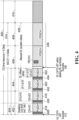
- the UE 110a may not have identified an end of the uplink burst 424 in the time slot 404 and therefore may not have identified a beginning of the downlink transmission opportunity 426 in the time slot 406. Therefore, in this example, the PUSCH 416 in the time slot 402 includes a CG-UCI 428, and the COT sharing information of the CG-UCI 428 includes a "disabling" indication indicating no downlink transmission opportunity, similar to the COT sharing information of the CG-UCI 358 shown in FIG. 3 .
- the PUSCH 418 includes a CG-UCI 430
- the COT sharing information of the CG-UCI 430 may therefore be similar to the COT sharing information of the COT sharing information of the CG-UCI 338 shown in FIG. 3 .
- the PUSCH 420 includes a CG-UCI 432, and the COT sharing information of the CG-UCI 432 may be similar to the COT sharing information of the CG-UCI 340 shown in FIG. 3 .
- the PUSCH 422 includes a CG-UCI 434, and the COT sharing information of the CG-UCI 434 may be similar to the COT sharing information of the CG-UCI 342 shown in FIG. 3 .
- the values of l and d in the embodiment of FIG. 4 are examples only, and alternative embodiments may include different indications of a time delay (or offset) to a beginning of a downlink transmission opportunity, and alternative embodiments may include different indications of a duration of the downlink transmission opportunity.
- the base station 170a initiates a downlink transmission 436 from the base station 170a to the UE 110a in the downlink transmission opportunity 426 after a DL LBT procedure 438 at the beginning of the time slot 406.
- the DL LBT procedure 438 may be similar to the DL LBT procedure 346 shown in FIG. 3
- the downlink transmission 436 may be similar to the downlink transmission 344 shown in FIG. 3 , although alternative embodiments may differ.
- a MCOT of COT initiated by a UE has N p, ⁇ time slots, where p represents the channel access priority class (CAPC) used to initiate the COT and ⁇ represents a numerology of the configured-grant time resource.
- p the channel access priority class
- the COT sharing information of the CG-UCI indicates a downlink transmission opportunity beginning in a same time slot as transmission of the CG-UCI.
- a downlink transmission in a same time slot as transmission of a CG-UCI may be described as a partial-slot downlink transmission.
- the C p, ⁇ combinations of ( l, d ) may be ordered in an ordered set of combinations of ( l, d ), and combinations in the ordered set of combinations of ( l, d ) may be identified by values of an index. Therefore, a value of an index may identify a combination in an ordered set of combinations of ( l , d ), and the value of an index therefore identifies the time delay, represented by the combination, from transmission of a CG-UCI to a beginning of a downlink transmission opportunity, and the value of an index also identifies the duration, represented by the combination, of the downlink transmission opportunity.
- each of the CG-UCIs 338, 340, 342, 358, 428, 430, 432, and 434 includes COT sharing information in addition to any other data in the CG-UCIs, and the COT sharing information includes either a "disabling" indication indicating no downlink transmission opportunity or an identifier of a combination in an ordered set of combinations of (/, d ).
- the number of possible values (or possible index values) of the COT sharing information of each of the CG-UCIs 338, 340, 342, 358, 428, 430, 432, and 434 for a particular p and for a particular ⁇ is 1 + C p , ⁇
- each of the CG-UCIs 338, 340, 342, 358, 428, 430, 432, and 434 may include COT sharing information encoded in at least B p, ⁇ bits, and the bits in the COT sharing information of the CG-UCIs may indicate an index value representing either a "disabling" indication indicating no downlink transmission opportunity or an identifier of a combination in an ordered set of combinations of ( l, d ).
- CG-UCIs according to other embodiments may differ as described below, for example.
- different configured-grant resources may be used for particular respective CAPCs.
- configured-grant resources may be used for more than one CAPC.
- COT sharing information in a CG-UCI may include an indicator of a CAPC p that the UE used to initiate the COT.
- COT sharing information of a CG-UCI may include two bits, a different number of bits, or a different indicator to indicate a CAPC p that the UE used to initiate the COT.
- an index value identified in COT sharing information of a CG-UCI may be a number encoded in B ⁇ bits and ranging from 0 to 2 B ⁇ - 1.
- an index value identified in COT sharing information of a CG-UCI may identify both a CAPC p that the UE used to initiate the COT and an identifier of a combination in an ordered set of combinations of ( l, d ) as shown in the following example.
- CIV Range Start CIV Range End CAPC p CIV Identifies 0 0 0 "Disabling" indication indicating no downlink transmission opportunity
- C 0, ⁇ 1 C 1, ⁇ 1
- One of C 1, ⁇ combinations of ( l , d ) ⁇ 1, ⁇ C 1, ⁇ + 1 C 1, ⁇ + C 2 , ⁇ 2
- One of C 2 , ⁇ combinations of ( l , d ) ⁇ 2 , ⁇ ⁇ 1, ⁇ + C 2 , ⁇ C 1, ⁇ + C 2 , ⁇ + C 3 , ⁇ 3
- One of C 3 , ⁇ combinations of ( l , d ) ⁇ 3 , ⁇ ⁇ 2 , ⁇ + C 3 , ⁇ C 1, ⁇ + C 2 , ⁇ + C 3 , ⁇ + C 4, ⁇ 4
- One of C 4, ⁇ combinations of ( l , d ) ⁇ 4 , ⁇ ⁇ 3 , ⁇ + C 4, ⁇ 2 B ⁇ - 1 None Reserved (if any)
- an index value of 0 indicates a "disabling" indication indicating no downlink transmission opportunity
- an index value from 1 to C 1 ⁇ indicates a respective combination of an ordered set of C 1, ⁇ combinations of ( l, d )
- an index value from ⁇ 1, ⁇ to C 1, ⁇ + C 2 ⁇ indicates a respective combination of an ordered set of C 2 , ⁇ combinations of ( l , d )
- p ranges from 0 to 4, so ⁇ 4, ⁇ CIV values are required.
- one or more index values or other indicators may indicate a CAPC p that the UE used to initiate the COT, a "disabling" indication indicating no downlink transmission opportunity, a time delay (or offset) to a beginning of a downlink transmission opportunity, a duration of the downlink transmission opportunity, or a combination of two or more thereof.
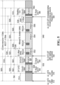
- FIG. 5 illustrates an example of a time resource 500 for configured grant by the UE 110a in an unlicensed spectrum in the cell 175a of the base station 170a according to one embodiment, although alternative embodiments may involve different UEs, different cells, and/or different base stations.
- the time resource 500 includes five time slots 502, 504, 506, 508, and 510, and the UE 110a attempted to initiate COT for an uplink transmission to the base station 170a in the time resource 500 by a first UL LBT procedure 512 at the beginning of the time slot 502.
- the first UL LBT procedure 512 failed because of a "busy" assessment.
- the UE 110a attempted again to initiate COT for an uplink transmission to the base station 170a in the time resource 500 by proceeding with a second UL LBT procedure 516 towards the next potential PUSCH starting point, which is after a delay 514 from the beginning of the time slot 502.
- the first UL LBT procedure 512 and the second UL LBT procedure 516 are CAT4 UL LBT procedures, but in alternative embodiments, a UE may attempt to initiate COT using other procedures.
- the second UL LBT procedure 516 was successful, and the UE 110a initiated COT having a MCOT 518 of four time slots 520, 522, 524, and 526 in the time resource 500.
- the COT in the MCOT 518 is therefore COT initiated by the UE 110a.
- the UE 110a transmits an uplink transmission to the base station 170a in a PUSCH 528 in the time slot 502 and in a PUSCH 530 in the time slot 504.
- the PUSCHs 528 and 530 therefore form an uplink burst 532 in an uplink transmission from the UE 110a to the base station 170a in the time resource 500 in the unlicensed spectrum in the cell 175a of the base station 170a.
- the uplink burst 532 does not occupy the entire time slot 504, and the uplink burst 532 does not extend into the time slots 506 and 508 that are within the MCOT 518. Therefore, the uplink burst 532 includes indications of a downlink transmission opportunity 534 (or, more generally, a transmission opportunity) during the COT in the MCOT 518.
- the downlink transmission opportunity 534 includes a partial-slot portion 536 of the downlink transmission opportunity 534 in a portion of the time slot 504 that is not occupied by the uplink burst 532.
- the downlink transmission opportunity 534 also includes a portion 538 of the downlink transmission opportunity 534 in the time slots 506 and 508.
- the PUSCH 528 in the time slot 502 includes a CG-UCI 540
- the COT sharing information of the CG-UCI 540 may therefore be similar to the COT sharing information of the of CG-UCI 340 or of the CG-UCI 342 as shown in FIG. 3 , except that the CG-UCI 540 also includes a "UL burst end" bit 542.
- the COT sharing information of the CG-UCI 540 also includes the "UL burst end" bit 542 indicating, with a bit value of '0' in this example, that the PUSCH 528 is not the end of the uplink burst 532.
- the PUSCH 530 in the time slot 504 includes a CG-UCI 544
- the "UL burst end” bit 546 is an indication that the beginning of the downlink transmission opportunity 534 is in the same time slot 504 of the COT in the MCOT 518 as the transmission of the CG-UCI 544
- the "UL burst end” bit 546 is an indication that the beginning of the downlink transmission opportunity 534 is in a same time slot of the COT as an end of an uplink burst including the transmission of the CG-UCI 544
- the "UL burst end” bit 546 is an indication of a time (in this example, the time being after the PUSCH 530 including the CG-UCI 544) of the beginning of the downlink transmission opportunity 534 within the same time slot 504 as the transmission of the CG-UCI 544.
- the values of l and d, and the "UL burst end" bits 542 and 546 are examples only.
- Alternative embodiments may include different indications of a time delay (or offset) to a beginning of a downlink transmission opportunity.
- Alternative embodiments may also include different indications of a duration of the downlink transmission opportunity.
- Alternative embodiments may also include different indications of whether a downlink transmission opportunity is in a same time slot of the COT as transmission of CG-UCI.
- Alternative embodiments may also include different indications of an end of an uplink burst.
- the base station 170a initiates a downlink transmission 548 from the base station 170a to the UE 110a in the downlink transmission opportunity 532 by a downlink DL LBT procedure 550 after the PUSCH 530 and in the time slot 504.
- the DL LBT procedure 550 is a CAT2 DL LBT procedure, which does not involve a random back-off, but in alternative embodiments, base station may initiate a downlink transmission using other procedures.
- the DL LBT procedure 550 was successful, and the downlink transmission 548 includes a first PDSCH 552 in the time slot 504, a second PDSCH 554 in the time slot 506, and a third PDSCH 556 in the time slot 508, although alternative embodiments may differ.
- an idle period 558 of at least 100 ⁇ s follows the downlink transmission 548, and after the idle period 558, the UE 110a attempts to resume uplink transmission in the COT of the MCOT 518 by a third UL LBT procedure 560 before the end of the time slot 508.
- the third UL LBT procedure 560 is a CAT2 UL LBT procedure, but in alternative embodiments, a UE may attempt to resume uplink transmission using other procedures.
- the third UL LBT procedure 560 was successful, and the UE 110a resumes uplink transmission in the COT of the MCOT 518 by transmitting a PUSCH 562 in the time slot 510.
- the PUSCH 562 includes a CG-UCI 564, and the COT sharing information of the CG-UCI 564 includes a "disabling” indication that may be similar to the "disabling” indication of the CG-UCI 358. Further, in the embodiment shown, in addition to the "disabling" indication, the COT sharing information of the CG-UCI 564 includes a "UL burst end” bit 566 indicating, with a bit value of '1' in this example, that the PUSCH 562 is the end of an uplink burst including the PUSCH 562.
- FIG. 6 illustrates an alternative to the embodiment of FIG. 5 .
- a time resource for configured grant by the UE 110a in an unlicensed spectrum in the cell 175a of the base station 170a includes time slots 602, 604, and 606 in COT initiated by the UE 110a and within a MCOT of the COT, although alternative embodiments may involve different UEs, different cells, and/or different base stations.
- the UE 110a transmits an uplink transmission to the base station 170a in a PUSCH 610 in the time slot 602 and in a PUSCH 612 in the time slot 602.
- the uplink burst 608 does not occupy the entire time slot 602, and the uplink burst 608 does not extend into the time slots 604 and 606 that are also within the MCOT. Therefore, the uplink burst 608 includes indications of a downlink transmission opportunity 614 (or, more generally, a transmission opportunity).
- a partial-slot portion of the downlink transmission opportunity 614 is in a portion of the time slot 602 that is not occupied by the uplink burst 606.
- Another portion of the downlink transmission opportunity 614 is in the time slots 604 and 606. Therefore, the downlink transmission opportunity 614 begins in the same time slot 602 as the PUSCHs 610 and 612.
- the portion of the downlink transmission opportunity 614 that begins after the time slot 602 has a duration of two time slots 604 and 606.
- the downlink transmission opportunity 614 has a duration of two time slots in addition to the partial-slot portion of the downlink transmission opportunity 614 in the same time slot 602 as the PUSCHs 610 and 612.
- the PUSCH 610 in the time slot 602 includes a CG-UCI 616
- the PUSCH 612 in the time slot 602 includes a CG-UCI 620
- each of the CG-UCIs 616 and 620 includes COT sharing information in addition to any other data in the CG-UCIs, and the COT sharing information includes either an identifier of a combination in an ordered set of combinations of ( l, d ) or a "disabling" indication indicating no downlink transmission opportunity, and the COT sharing information of each of the CG-UCIs 616 and 620 also includes a "UL burst end" bit. Therefore, in the embodiments of FIG.
- CG-UCIs may differ.
- a UE may blank one or more downlink symbols based on the numerology or SCS of the active BWP after the end of the last PUSCH of an uplink burst to create a switching gap between the uplink burst and a subsequent downlink transmission
- the "UL burst end" of a CG-UCI may be two or more bits to indicate a beginning of a downlink transmission opportunity for the subsequent downlink transmission after the one or more blanked downlink symbols.
- Still other CG-UCIs are described below.
- the "UL burst end" bit 546 or 622 in the COT sharing information of a CG-UCI indicates a time of a beginning of a downlink transmission opportunity within a same time slot as the transmission of the CG-UCI and indicates the time of the beginning of the downlink transmission opportunity in a same time slot of the COT as an end of an uplink burst including the transmission of the CG-UCI.
- the "UL burst end” bits require at least one additional bit in each of the CG-UCIs 616 and 620.
- the CG-UCI may indicate an index value that may indicate a beginning of a downlink transmission opportunity within a same time slot as the transmission of the CG-UCI, or in a same time slot of the COT as an end of an uplink burst including the transmission of the CG-UCI, without necessarily requiring an additional "UL burst end" bit as in the embodiment of FIG. 6 .
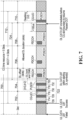
- FIG. 7 illustrates an example of a time resource 700 for configured grant by the UE 110a in an unlicensed spectrum in the cell 175a of the base station 170a according to one embodiment, although alternative embodiments may involve different UEs, different cells, and/or different base stations.
- the time resource 700 includes five time slots 702, 704, 706, 708, and 710, and the UE 110a initiated a COT having a MCOT 712 of four time slots in the time resource 700.
- the UE 110a transmits an uplink transmission to the base station 170a in a PUSCH 714 in the time slot 702, in a PUSCH 716 in the time slot 702, in a PUSCH 718 in the time slot 704, and in a PUSCH 720 in the time slot 704.
- the PUSCHs 714, 716, 718, and 720 therefore form an uplink burst 722 in an uplink transmission from the UE 110a to the base station 170a in the time resource 700 in the unlicensed spectrum in the cell 175a of the base station 170a.
- the uplink burst 722 does not occupy the entire time slot 704, and the uplink burst 722 does not extend into the time slots 706 and 708 that are within the MCOT 712. Therefore, the uplink burst 722 includes indications of a downlink transmission opportunity 724 (or, more generally, a transmission opportunity) during the COT in the MCOT 712.
- a partial-slot portion of the downlink transmission opportunity 724 is in a portion of the time slot 704 that is not occupied by the uplink burst 722.
- Another portion of the downlink transmission opportunity 724 is in the time slots 706 and 708. Therefore, the downlink transmission opportunity 724 begins in the same time slot 704 as the PUSCHs 718 and 720.
- the portion of the downlink transmission opportunity 724 that begins after the time slot 704 has a duration of two time slots 706 and 708.
- the downlink transmission opportunity 724 has a duration of two time slots in addition to the partial-slot portion of the downlink transmission opportunity 724 in the same time slot 704 as the PUSCHs 718 and 720.
- the PUSCH 714 in the time slot 702 includes a CG-UCI 726
- the PUSCH 716 in the time slot 702 includes a CG-UCI 728.
- the COT sharing information of the CG-UCIs 726 and 728 each includes an indication that the downlink transmission opportunity 724 begins one time slot after the time slot 702, and indications that the downlink transmission opportunity 702 has a duration of two time slots in addition to the partial-slot portion of the downlink transmission opportunity 724 in the same time slot 704 as the PUSCHs 718 and 720.
- the COT sharing information of the CG-UCIs 726 and 728 may therefore be similar to the COT sharing information of the CG-UCIs 340 or 342 as shown in FIG. 3 .
- the PUSCH 718 in the time slot 704 includes a CG-UCI 730
- the slot 704 includes 14 symbols, the PUSCH 718 occupied the first four symbols of the slot 704, and the PUSCH 720 occupied the first three symbols of the slot 704. Therefore, in this example, the PUSCH 720 in the time slot 704 includes a CG-UCI 732, and the COT sharing information of the CG-UCI 732 includes an indication that a beginning of the downlink transmission opportunity 724 is after the first seven symbols in the time slot 704, indicated by "UL burst end OS#6" in FIG. 7 , and the COT sharing information of the CG-UCI 732 includes an indication of a ending symbol of the UL burst 722.
- the COT sharing information of the CG-UCI 732 includes an indication of an uplink burst end symbol number N ULE indicating a symbol in the time slot 704 before the beginning of the downlink transmission opportunity 724.
- the number of symbols in a slot when a uplink burst could end may be referred to as a number of uplink burst endpoints N ULBEP .
- sharing information of a CG-UCI may indicate a PUSCH that is the last PUSCH of an uplink burst that ends in a time slot having a partial-slot downlink opportunity. For example, if a time slot includes 14 symbols, and if a PUSCH has a length of at least two symbols, then the time slot may include up to seven PUSCHs. In that example, if an uplink burst ends during the time slot and the time slot includes a partial-slot downlink opportunity, then the time slot may include up to six PUSCHs, and an indicator of a number from the set ⁇ 0, 1, ...
- 5 ⁇ may indicate which PUSCH in the time slot is the last PUSCH of the uplink burst.
- Such an indicator of a last PUSCH of an uplink burst may therefore, in addition to or alternatively to other indicators such as those described herein, indicate a symbol of a beginning of a downlink transmission opportunity.
- an index value identified by COT sharing information of a CG-UCI may identify both a CAPC p that the UE used to initiate the COT and an identifier of a combination in an ordered set of combinations of ( l, d ).
- an index value identified by COT sharing information of a CG-UCI may identify either both a CAPC p that the UE used to initiate the COT and an identifier of a combination in an ordered set of combinations of ( l , d ) or a time of the beginning of the downlink transmission opportunity in the same time slot of the COT as the transmission of the CG-UCI, as shown in the following example.
- CIV Range Start CIV Range End CAPC p CIV Identifies 0 0 0 "Disabling" indication indicating no downlink transmission opportunity
- C 0,1 1
- C 1,1 10 1
- One of C 4 , ⁇ N 4,
- a CIV may be decoded as follows.
- the COT sharing information of the CG-UCI 732 includes an indication that a beginning of the downlink transmission opportunity 724 is after the first seven symbols in the time slot 704, indicated by "UL burst end OS#6" in FIG. 7 .
- one or more index values or other indicators may indicate a CAPC p that the UE used to initiate the COT, a "disabling" indication indicating no downlink transmission opportunity, a time delay (or offset) to a beginning of a downlink transmission opportunity, a duration of the downlink transmission opportunity, a time of the beginning of the downlink transmission opportunity in the same time slot as the transmission of the CG-UCI, or a combination of two or more thereof.
- the order of transmitting the COT sharing information of the CG-UCIs 730 and 732 may be reversed without impacting the collective COT sharing information indicated to the base station 170a.
- the example of FIG. 7 may then continue with a downlink transmission in the downlink transmission opportunity from the base station 170a to the UE 110a in the downlink transmission opportunity 614 as described above with reference to FIG. 5 , for example.
- FIG. 8 illustrates an example of a time resource 800 for configured grant by the UE 110a in an unlicensed spectrum in the cell 175a of the base station 170a according to one embodiment, although alternative embodiments may involve different UEs, different cells, and/or different base stations.
- the time resource 800 includes five time slots 802, 804, 806, 808, and 810, and the UE 110a initiated a COT having a MCOT 812 of four time slots in the time resource 800.
- the UE 110a transmits an uplink transmission to the base station 170a in a PUSCH 814 in the time slot 802 and in a PUSCH 816 in the time slot 804.
- the PUSCHs 814 and 816 therefore form an uplink burst 818 in an uplink transmission from the UE 110a to the base station 170a in the time resource 800 in the unlicensed spectrum in the cell 175a of the base station 170a.
- the PUSCH 814 in the time slot 802 includes a CG-UCI 820
- the PUSCH 816 in the time slot 804 includes a CG-UCI 822.
- the COT sharing information of the CG-UCI 820 includes an indication that a beginning of a downlink transmission opportunity 824 (or, more generally, a transmission opportunity) is after the first seven symbols, indicated by "UL burst end OS#6" in FIG. 8 .
- the CG-UCI 820 is in the time slot 802, and the first six symbols of the time slot 802 have already passed, so the CG-UCI 820 indicates instead that the beginning of the downlink transmission opportunity 824 is after the first seven symbols of the next time slot, namely the time slot 804, or more generally, after the first seven symbols of a subsequent slot in the UL burst.
- the CG-UCI 820 which includes the indication of the beginning of the downlink transmission opportunity 824, may be in the PUSCH 814 before the PUSCH 816, which is the last PUSCH of the an uplink burst 818 and the last PUSCH before the beginning of the downlink transmission opportunity 824.
- the indication of the beginning of the downlink transmission opportunity 824 in the COT sharing information of the CG-UCI 820 is an indication that the beginning of the downlink transmission opportunity 824 is in a same time slot of the COT as an end of an uplink burst including the transmission of the CG-UCI 820
- the indication of the beginning of the downlink transmission opportunity 824 in the COT sharing information of the CG-UCI 820 is an indication of a time (in this example, the time being after the first seven symbols of the next time slot, namely the time slot 804) of the beginning of the downlink transmission opportunity 824.
- a base station may configure a UE to use a bit field having a configured payload size of B p, ⁇ bits for COT sharing information in CG-UCIs in addition to any bits that may be required for other data in the CG-UCIs.
- different configured-grant resources may be used for particular respective CAPCs, and B p, ⁇ may be determined without any bits to indicate the CAPC p that the UE used to initiate the COT.
- COT sharing information of a CG-UCI may include two bits, or a different number of bits, to indicate a CAPC p that the UE used to initiate the COT, and B p, ⁇ may be determined to include any bits that indicate the CAPC p that the UE used to initiate the COT.
- an index value may indicate a CAPC p that the UE used to initiate the COT, in which case B p, ⁇ may be determined without any bits to indicate the CAPC p that the UE used to initiate the COT.
- B p, ⁇ may be determined to accommodate the largest possible p, such as B 4, ⁇ for example, irrespective of the actual CAPC p that the UE used to initiate the COT, to avoid a variable size of the CG-UCI.
- a MCOT of COT initiated by a UE has N p, ⁇ time slots.
- a configured payload size B p, ⁇ may be determined as the number of bits required for all CIV values that may be required.
- the number of CIV values that may be required may be determined according to one of the examples above, or in other ways.
- N p, ⁇ is based on a reference numerology or SCS ⁇ ref
- indications of time delay l and indications of duration d represent more than one time slot and therefore have coarser granularity than when N p, ⁇ is based on a numerology or SCS ⁇ of an active BWP.
- the actual duration of the downlink transmission opportunity in the numerology or SCS ⁇ of an active BWP may be longer than the duration indicated by d, and the base station may transmit a downlink transmission having a duration of d ⁇ 2 ⁇ - ⁇ ref time slots, in addition to a partial-slot DL transmission if indicated.
- the COT sharing information may require an additional slot offset adjustment value j to indicate a slot time delay in a number of slots.
- j the COT sharing information
- FIG. 9 illustrates a time resource 900 according to one embodiment for configured grant by the UE 110a in an unlicensed spectrum in the cell 175a of the base station 170a according to one embodiment, although alternative embodiments may involve different UEs, different cells, and/or different base stations.
- the time resource 900 includes four time slots 902, 904, 906, and 908, and the UE 110a initiated a COT having a MCOT 910 of the same four time slots 902, 904, 906, and 908 in the time resource 900.
- the UE 110a transmits an uplink transmission to the base station 170a in a PUSCH 912 in the time slot 902, in a PUSCH 914 in the time slot 902, and in a PUSCH 916 in the time slot 904.
- the PUSCHs 912, 914, and 916 therefore form an uplink burst 918 in an uplink transmission from the UE 110a to the base station 170a in the time resource 900 in the unlicensed spectrum in the cell 175a of the base station 170a.
- the base station 170a initiates a downlink transmission including a PDSCH 920 in the time slot 904 by a downlink DL LBT procedure 922.
- the base station 170a may blank one or more downlink symbols based on the numerology or SCS of the active BWP and a CP extension not exceeding one symbol duration to provide a switching gap between the uplink transmission and the downlink transmission.
- the switching gap between the uplink burst 918 and the PDSCH 920 may be 16 ⁇ s or 25 ⁇ s if the DL LBT procedure 922 is a CAT2 DL LBT procedure.
- the switching gap between the uplink burst 918 and the PDSCH 920 may be 16 ⁇ s if the DL LBT procedure 922 is a category 1 (CAT1) LBT, i.e., direct transmission without LBT performed in the switching gap.
- CAT1 LBT category 1
- the UE 110a resumes uplink transmission in the COT of the MCOT 910 after a gap 924 of at least 100 ⁇ s from the PDSCH 920 to the first PUSCH 926 of the resumed uplink transmission.
- the resumed uplink transmission may be resumed by a CAT2 UL LBT procedure 928 in a switching gap, which may be 25 ⁇ s, for example.
- the UE 110a may resume uplink transmission according to one or more uplink grants that may have been received in the PDCCH 921 included in the downlink transmission including the PDSCH 920.
- Such uplink grants may indicate an LBT type and a switching gap duration for resuming the uplink transmission.
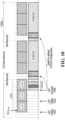
- FIG. 10 illustrates an example of a time resource 1000 for configured grant by the UE 110a in an unlicensed spectrum in the cell 175a of the base station 170a according to one embodiment, although alternative embodiments may involve different UEs, different cells, and/or different base stations.
- the UE 110a attempted to initiate COT for an uplink transmission to the base station 170a in the time resource 1000 by a first UL LBT procedure 1002 and later by a second UL LBT procedure 1004.
- the UL LBT procedures 1002 and 1004 failed.
- the UE 110a attempted to initiate COT for an uplink transmission to the base station 170a in the time resource 1000 by a third UL LBT procedure 1006, and the third UL LBT procedure 1006 succeeded. Therefore, following UL LBT procedure 1006, the UE 110a initiated COT in the time resource 1000.
- the UE 110a initiated the COT in the time resource 1000, the UE 110a switched to another configured-grant configuration, which may be a default configuration, including two seven-symbol slots per time slot, and one 14-symbol PUSCH per slot.
- the embodiment of FIG. 10 is an example only, and in alternative embodiments, a UE may switch between two or more different configured-grant configurations that may differ from the two configured-grant configurations that are shown in FIG. 10 .
- a UE may be configured with a hybrid configuration including parameters for different configured-grant configurations. For example, in some embodiments, to avoid control overhead, a UE may be configured with a CG-UCI payload size accounting for COT sharing information for only CG-PUSCHs of a default configuration. In other embodiments, a UE may be configured with a first CG-UCI payload size accounting for a first COT sharing information for a default configuration, and may be configured with a second smaller CG-UCI payload size accounting for a second COT sharing information for CG-PUSCHs of an initial configuration by reducing N p, ⁇ or eliminating some combinations of ( l, d ) to reflect shorter mini-slots per time slot.
- the CG-UCI payload size including the COT sharing information size, along with the resource mapping beta offset value may be determined based on the CG PUSCH of the smallest size, whereas rate matching may be used by the UE to map the CG-UCI payload bits to the larger resources on the larger CG PUSCHs as determined by the beta offset value.
- COT may be shared in sidelink transmissions between two UEs, such as the UEs 110a and 110b, for example. Sharing of COT in sidelink transmissions may be similar to sharing of COT for downlink transmissions as described above, except that sharing of COT in sidelink transmissions would involve sharing COT in sidelink configured grant, rather than sharing COT in configured grant from a base station.
- the sidelink configured grant resources may be determined by the base station or may be selected from a configured resource pool by the COT transmitting UE initiating the COT.
- the base station may be using a higher transmit power level than that of the UE that initiated the UL COT.
- the base station may apply one or more of the following techniques:
- a UE may flexibly indicate a time delay (or offset) to a beginning of a downlink transmission opportunity during COT, and a duration of the downlink transmission opportunity.
- the beginning and the duration of the downlink transmission opportunity may be identified for different reasons, such as allowing a switching gap as may be appropriate between an uplink transmission and a subsequent downlink transmission, or between a downlink transmission and a subsequent uplink transmission.
- COT sharing information may encode an indication of a time delay (or offset) to a beginning of a downlink transmission, a duration of the downlink transmission opportunity, a CAPC that a UE used to initiate the COT, or a combination of two or more thereof using a CIV or other indications such as those described above, for example.
- Embodiments such as those described above may facilitate multiple switching points, for example uplink-downlink-uplink or uplink-downlink-uplink-downlink.
- embodiments such as those described above may make relatively efficient use of available resources when compared to other methods and apparatuses.
Landscapes
- Engineering & Computer Science (AREA)
- Computer Networks & Wireless Communication (AREA)
- Signal Processing (AREA)
- Mobile Radio Communication Systems (AREA)
Applications Claiming Priority (4)
| Application Number | Priority Date | Filing Date | Title |
|---|---|---|---|
| US201962911161P | 2019-10-04 | 2019-10-04 | |
| US17/036,517 US11792848B2 (en) | 2019-10-04 | 2020-09-29 | Methods and apparatuses for cot sharing in unlicensed spectrum |
| PCT/CN2020/119216 WO2021063385A1 (en) | 2019-10-04 | 2020-09-30 | Methods and apparatuses for cot sharing in unlicensed spectrum |
| EP20873215.6A EP4042783B1 (de) | 2019-10-04 | 2020-09-30 | Verfahren und vorrichtungen für gemeinsame cot-nutzung in einem unlizenzierten spektrum |
Related Parent Applications (2)
| Application Number | Title | Priority Date | Filing Date |
|---|---|---|---|
| EP20873215.6A Division EP4042783B1 (de) | 2019-10-04 | 2020-09-30 | Verfahren und vorrichtungen für gemeinsame cot-nutzung in einem unlizenzierten spektrum |
| EP20873215.6A Division-Into EP4042783B1 (de) | 2019-10-04 | 2020-09-30 | Verfahren und vorrichtungen für gemeinsame cot-nutzung in einem unlizenzierten spektrum |
Publications (2)
| Publication Number | Publication Date |
|---|---|
| EP4518392A2 true EP4518392A2 (de) | 2025-03-05 |
| EP4518392A3 EP4518392A3 (de) | 2025-06-18 |
Family
ID=75275145
Family Applications (2)
| Application Number | Title | Priority Date | Filing Date |
|---|---|---|---|
| EP20873215.6A Active EP4042783B1 (de) | 2019-10-04 | 2020-09-30 | Verfahren und vorrichtungen für gemeinsame cot-nutzung in einem unlizenzierten spektrum |
| EP24221474.0A Pending EP4518392A3 (de) | 2019-10-04 | 2020-09-30 | Verfahren und vorrichtungen zur gemeinsamen nutzung eines cot in einem unlizenzierten spektrum |
Family Applications Before (1)
| Application Number | Title | Priority Date | Filing Date |
|---|---|---|---|
| EP20873215.6A Active EP4042783B1 (de) | 2019-10-04 | 2020-09-30 | Verfahren und vorrichtungen für gemeinsame cot-nutzung in einem unlizenzierten spektrum |
Country Status (7)
| Country | Link |
|---|---|
| US (4) | US11792848B2 (de) |
| EP (2) | EP4042783B1 (de) |
| JP (2) | JP7269441B2 (de) |
| KR (1) | KR102801748B1 (de) |
| CN (2) | CN114467347B (de) |
| MX (1) | MX2022003987A (de) |
| WO (1) | WO2021063385A1 (de) |
Families Citing this family (40)
| Publication number | Priority date | Publication date | Assignee | Title |
|---|---|---|---|---|
| US11677677B2 (en) * | 2018-08-13 | 2023-06-13 | Bae Systems Information And Electronic | Tiered unassisted discovery in directional RF networks |
| WO2020146833A1 (en) * | 2019-01-11 | 2020-07-16 | Apple Inc. | Cot sharing procedure for configured grants in nr systems operating on unlicensed spectrum |
| CN114745803B (zh) | 2019-10-13 | 2023-10-31 | Oppo广东移动通信有限公司 | 共享信道占用时间的方法和设备、终端设备、及网络设备 |
| CN117295180B (zh) * | 2019-11-08 | 2024-11-05 | Oppo广东移动通信有限公司 | 非授权频谱上的数据传输方法、装置、设备及存储介质 |
| CN115209560B (zh) * | 2019-11-08 | 2024-01-16 | Oppo广东移动通信有限公司 | 信息传输方法、相关设备和存储介质 |
| PH12022550970A1 (en) * | 2019-11-08 | 2023-09-25 | Qualcomm Inc | Configured grant channel occupancy time sharing procedure |
| WO2021110088A1 (en) * | 2019-12-03 | 2021-06-10 | Guangdong Oppo Mobile Telecommunications Corp., Ltd. | A method of uplink transmission in base station shared channel occupancy time |
| CN114762374A (zh) * | 2019-12-06 | 2022-07-15 | Oppo广东移动通信有限公司 | 用于信道占用时间共享的方法、用户设备、基站和计算机可读介质 |
| CN113260050B (zh) * | 2020-02-11 | 2023-04-07 | 维沃移动通信有限公司 | Iab网络的复用调度方法和iab节点 |
| US12356424B2 (en) * | 2020-02-13 | 2025-07-08 | Panasonic Intellectual Property Corporation Of America | Terminal and communication method |
| US11533753B2 (en) * | 2020-03-17 | 2022-12-20 | Qualcomm Incorporated | Adaptive time-varying frame pattern for frame based equipment (FBE) channel access |
| WO2021189340A1 (en) * | 2020-03-26 | 2021-09-30 | Qualcomm Incorporated | Continuous transmission for new radio-unlicensed (nr-u) uplink |
| WO2021207957A1 (en) * | 2020-04-15 | 2021-10-21 | Qualcomm Incorporated | Techniques for ue-to-ue channel occupancy time sharing in unlicensed spectrum |
| CN115443705B (zh) * | 2020-04-22 | 2025-12-02 | 联想(北京)有限公司 | 用于共享信道占用时间的方法及设备 |
| CN115669170B (zh) * | 2020-05-27 | 2024-08-30 | 高通股份有限公司 | 与用于侧链路通信的信道占用时间(cot)有关的多个起始点 |
| US11812474B2 (en) * | 2020-06-18 | 2023-11-07 | Qualcomm Incorporated | Sub-channel-based occupancy time sharing for unlicensed sidelink |
| US12526842B2 (en) | 2020-07-29 | 2026-01-13 | Lenovo (Singapore) Pte. Ltd. | Early termination of an uplink transmission |
| WO2022154397A1 (ko) | 2021-01-15 | 2022-07-21 | 엘지전자 주식회사 | 무선 통신 시스템에서 신호 송수신 방법 및 장치 |
| US12402170B2 (en) * | 2021-01-15 | 2025-08-26 | Qualcomm Incorporated | Receiver-side assistance information using multiple uplink transmit opportunities |
| WO2022185293A1 (en) * | 2021-03-05 | 2022-09-09 | Lenovo (Singapore) Pte. Ltd. | Channel occupancy time sharing information |
| US12250721B2 (en) | 2021-04-02 | 2025-03-11 | Qualcomm Incorporated | Starting a channel occupancy time after a directional listen-before-talk |
| EP4094469B1 (de) * | 2021-04-06 | 2025-08-27 | Apple Inc. | Verfahren zur signalisierung der klarkanalzugangsleistung in der kanalbelegungszeit |
| EP4084547B1 (de) * | 2021-04-26 | 2023-08-30 | Mitsubishi Electric R&D Centre Europe B.V. | Autonome gemeinsame funkressourcenbenutzung zwischen endgeräten für gerät-zu-gerät-kommunikation |
| CN115314174B (zh) * | 2021-05-08 | 2024-09-03 | 维沃移动通信有限公司 | 传输方法、装置、设备及可读存储介质 |
| WO2022240053A1 (ko) * | 2021-05-10 | 2022-11-17 | 엘지전자 주식회사 | 비면허 대역에서 신호를 송수신하는 방법 및 이를 위한 장치 |
| US11844108B2 (en) * | 2021-06-07 | 2023-12-12 | Nokia Technologies Oy | Channel access for semi-static uplink resources |
| US12302394B2 (en) * | 2021-08-13 | 2025-05-13 | Asustek Computer Inc. | Method and apparatus for listen before talk for sidelink transmission in a wireless communication system |
| CN117999843A (zh) * | 2021-09-24 | 2024-05-07 | 高通股份有限公司 | 信道占用时间(cot)共享 |
| CN118140581A (zh) * | 2021-12-17 | 2024-06-04 | Oppo广东移动通信有限公司 | 无线通信方法、装置、终端设备、存储介质和程序产品 |
| CN116419421B (zh) * | 2022-01-10 | 2025-11-11 | 大唐移动通信设备有限公司 | 确定数据通信的可用时间长度的方法、装置、设备及介质 |
| US20260122673A1 (en) * | 2022-02-11 | 2026-04-30 | Mediatek Singapore Pte. Ltd. | Methods and apparatus of channel occupancy time (cot) sharing in sidelink unlicensed communication systems |
| AU2023258288A1 (en) * | 2022-04-20 | 2024-10-31 | Panasonic Intellectual Property Corporation Of America | Communication device and communication method |
| US20230379921A1 (en) * | 2022-05-23 | 2023-11-23 | Qualcomm Incorporated | Uplink extended reality scheduling |
| CN115336359B (zh) * | 2022-07-13 | 2026-04-07 | 北京小米移动软件有限公司 | 辅助信息上报方法、装置、存储介质、终端以及网络侧设备 |
| US20250317965A1 (en) * | 2022-07-27 | 2025-10-09 | Qualcomm Incorporated | Communications using multiple transmission opportunities in multiple listen-before-talk (lbt) sub-bands |
| WO2024060100A1 (en) * | 2022-09-21 | 2024-03-28 | Nec Corporation | Method, device and computer readable medium for communications |
| US12538337B2 (en) | 2022-09-30 | 2026-01-27 | Electronics And Telecommunications Research Institute | Method and apparatus for sidelink communication in unlicensed band |
| WO2024250298A1 (zh) * | 2023-06-09 | 2024-12-12 | 北京小米移动软件有限公司 | 一种确定时隙数量的方法及装置 |
| JP2025054548A (ja) * | 2023-09-26 | 2025-04-08 | Kddi株式会社 | 基地局装置、端末装置及び無線通信方法 |
| WO2025065657A1 (en) * | 2023-09-28 | 2025-04-03 | Nokia Shanghai Bell Co., Ltd. | Uplink control informaiton reporting |
Family Cites Families (19)
| Publication number | Priority date | Publication date | Assignee | Title |
|---|---|---|---|---|
| CN105592478A (zh) | 2014-11-07 | 2016-05-18 | 中兴通讯股份有限公司 | 信号的检测处理方法及装置 |
| CN105992345A (zh) | 2015-01-27 | 2016-10-05 | 中兴通讯股份有限公司 | 非授权载波资源的使用方法及装置 |
| KR102658360B1 (ko) | 2015-04-09 | 2024-04-17 | 삼성전자주식회사 | 비면허 대역을 사용하는 셀룰러 네트워크에서의 자원할당 방법 및 그 장치 |
| US10687345B2 (en) | 2015-12-31 | 2020-06-16 | Lg Electronics Inc. | Method for transmitting and receiving uplink signal in wireless communication system supporting unlicensed band and apparatus for supporting same |
| WO2017171613A1 (en) * | 2016-04-01 | 2017-10-05 | Telefonaktiebolaget Lm Ericsson (Publ) | A wireless device, a network node and methods therein for improved signalling in a wireless communications network |
| US20170325216A1 (en) | 2016-05-09 | 2017-11-09 | Sharp Laboratories Of America, Inc. | User equipments, base stations and methods |
| CN107769830B (zh) | 2016-08-19 | 2022-10-11 | 中兴通讯股份有限公司 | 协同工作子状态的方法、装置及系统 |
| CN110100466B (zh) * | 2016-12-21 | 2021-06-01 | 华为技术有限公司 | 未许可频谱中分布式网络辅助基于帧的设备兼容的用户设备协作的服务质量区分方法 |
| US10362593B2 (en) | 2017-09-01 | 2019-07-23 | Huawei Technologies Co., Ltd. | Grant-free uplink transmission in unlicensed spectrum |
| US12089253B2 (en) * | 2019-02-15 | 2024-09-10 | Apple Inc. | System and method for channel occupancy time (COT) sharing in an unlicensed spectrum |
| US20220150917A1 (en) * | 2019-03-15 | 2022-05-12 | Telefonaktiebolaget Lm Ericsson (Publ) | Channel Occupancy Time Interval in Unlicensed Frequency Spectrum |
| US10945287B2 (en) * | 2019-03-29 | 2021-03-09 | Qualcomm Incorporated | Uplink (UL) to downlink (DL) channel occupancy time (COT) sharing with scheduled UL in new radio-unlicensed (NR-U) |
| JP7250958B2 (ja) * | 2019-04-29 | 2023-04-03 | アップル インコーポレイテッド | 無認可スペクトル上で動作する新無線システムにおけるアップリンク送信 |
| WO2020260584A1 (en) | 2019-06-28 | 2020-12-30 | Telefonaktiebolaget Lm Ericsson (Publ) | Signalling channel access parameters for uplink transmissions |
| US20220272754A1 (en) * | 2019-08-09 | 2022-08-25 | Lenovo (Beijing) Limited | Method and Apparatus for Sharing Channel Occupancy Time |
| US11606811B2 (en) * | 2019-08-26 | 2023-03-14 | Qualcomm Incorporated | Techniques for determining resources for communicating over an acquired channel |
| US11672034B2 (en) * | 2019-09-25 | 2023-06-06 | Qualcomm Incorporated | Channel occupancy time (COT) sharing for sidelink |
| CN115443705B (zh) * | 2020-04-22 | 2025-12-02 | 联想(北京)有限公司 | 用于共享信道占用时间的方法及设备 |
| CN115669171A (zh) * | 2020-05-29 | 2023-01-31 | 奥罗佩法国有限责任公司 | 用户设备及其在共享频谱中进行传输的方法 |
-
2020
- 2020-09-29 US US17/036,517 patent/US11792848B2/en active Active
- 2020-09-30 JP JP2022520648A patent/JP7269441B2/ja active Active
- 2020-09-30 MX MX2022003987A patent/MX2022003987A/es unknown
- 2020-09-30 WO PCT/CN2020/119216 patent/WO2021063385A1/en not_active Ceased
- 2020-09-30 KR KR1020227014378A patent/KR102801748B1/ko active Active
- 2020-09-30 CN CN202080068772.2A patent/CN114467347B/zh active Active
- 2020-09-30 CN CN202510772207.9A patent/CN120547575A/zh active Pending
- 2020-09-30 EP EP20873215.6A patent/EP4042783B1/de active Active
- 2020-09-30 EP EP24221474.0A patent/EP4518392A3/de active Pending
-
2022
- 2022-09-14 US US17/944,632 patent/US11979907B2/en active Active
-
2023
- 2023-04-21 JP JP2023069721A patent/JP7613814B2/ja active Active
-
2024
- 2024-03-15 US US18/606,858 patent/US12408201B2/en active Active
-
2025
- 2025-07-29 US US19/283,959 patent/US20260032721A1/en active Pending
Also Published As
| Publication number | Publication date |
|---|---|
| WO2021063385A1 (en) | 2021-04-08 |
| CN114467347A (zh) | 2022-05-10 |
| US20210105815A1 (en) | 2021-04-08 |
| JP2023113604A (ja) | 2023-08-16 |
| JP2022550597A (ja) | 2022-12-02 |
| US20230070645A1 (en) | 2023-03-09 |
| JP7613814B2 (ja) | 2025-01-15 |
| CN120547575A (zh) | 2025-08-26 |
| EP4042783B1 (de) | 2025-01-22 |
| US20240244660A1 (en) | 2024-07-18 |
| EP4042783A4 (de) | 2022-12-07 |
| EP4042783C0 (de) | 2025-01-22 |
| EP4042783A1 (de) | 2022-08-17 |
| JP7269441B2 (ja) | 2023-05-08 |
| KR102801748B1 (ko) | 2025-04-28 |
| US11979907B2 (en) | 2024-05-07 |
| MX2022003987A (es) | 2022-07-21 |
| US12408201B2 (en) | 2025-09-02 |
| US11792848B2 (en) | 2023-10-17 |
| CN114467347B (zh) | 2025-07-11 |
| EP4518392A3 (de) | 2025-06-18 |
| KR20220070295A (ko) | 2022-05-30 |
| US20260032721A1 (en) | 2026-01-29 |
Similar Documents
| Publication | Publication Date | Title |
|---|---|---|
| US12408201B2 (en) | Methods and apparatuses for COT sharing in unlicensed spectrum | |
| CN114009123B (zh) | 在未许可频谱中使用配置授权进行上行传输的方法和装置 | |
| CN111788856B (zh) | 用于非授权频谱中的带宽指示的方法和装置 | |
| EP3606243B1 (de) | Verfahren und vorrichtung zur anzeige des slotformats einer unlizenzierten zelle in einem drahtloskommunikationssystem | |
| US10542439B2 (en) | Multi-subframe grant with scheduling of both data and control channels | |
| EP3459314B1 (de) | Planung mehrerer unterrahmen in einem unlizenzierten spektrum | |
| US20200052865A1 (en) | Method and apparatus for slot format indication for an ending slot in unlicensed spectrum in a wireless communication system | |
| CN110447298B (zh) | 在非授权带中发送物理信道的方法、装置和系统 | |
| US20220046670A1 (en) | Method and apparatus for distributed resource allocation in a wireless communication system | |
| CN108293268A (zh) | 非授权带中的信道接入的方法、设备和系统 | |
| CN107567720A (zh) | 用于确定在通信网络中争用窗口大小的通信装置及其中的方法 | |
| CN113747599B (zh) | 用户设备、基站及其方法 | |
| CN120188424A (zh) | 在未许可频带上执行侧链路通信的方法及设备 | |
| HK40074544B (en) | Method and apparatus of indicating aggregation number in a wireless communication system |
Legal Events
| Date | Code | Title | Description |
|---|---|---|---|
| PUAI | Public reference made under article 153(3) epc to a published international application that has entered the european phase |
Free format text: ORIGINAL CODE: 0009012 |
|
| STAA | Information on the status of an ep patent application or granted ep patent |
Free format text: STATUS: THE APPLICATION HAS BEEN PUBLISHED |
|
| AC | Divisional application: reference to earlier application |
Ref document number: 4042783 Country of ref document: EP Kind code of ref document: P |
|
| AK | Designated contracting states |
Kind code of ref document: A2 Designated state(s): AL AT BE BG CH CY CZ DE DK EE ES FI FR GB GR HR HU IE IS IT LI LT LU LV MC MK MT NL NO PL PT RO RS SE SI SK SM TR |
|
| PUAL | Search report despatched |
Free format text: ORIGINAL CODE: 0009013 |
|
| AK | Designated contracting states |
Kind code of ref document: A3 Designated state(s): AL AT BE BG CH CY CZ DE DK EE ES FI FR GB GR HR HU IE IS IT LI LT LU LV MC MK MT NL NO PL PT RO RS SE SI SK SM TR |
|
| RIC1 | Information provided on ipc code assigned before grant |
Ipc: H04W 74/0808 20240101ALI20250512BHEP Ipc: H04W 16/14 20090101AFI20250512BHEP |
|
| STAA | Information on the status of an ep patent application or granted ep patent |
Free format text: STATUS: THE APPLICATION IS DEEMED TO BE WITHDRAWN |