EP4518440A1 - Kommunikationsverfahren, endgerät und wifi-vorrichtung - Google Patents
Kommunikationsverfahren, endgerät und wifi-vorrichtung Download PDFInfo
- Publication number
- EP4518440A1 EP4518440A1 EP22938909.3A EP22938909A EP4518440A1 EP 4518440 A1 EP4518440 A1 EP 4518440A1 EP 22938909 A EP22938909 A EP 22938909A EP 4518440 A1 EP4518440 A1 EP 4518440A1
- Authority
- EP
- European Patent Office
- Prior art keywords
- terminal
- channel
- signal
- frequency domain
- domain resources
- Prior art date
- Legal status (The legal status is an assumption and is not a legal conclusion. Google has not performed a legal analysis and makes no representation as to the accuracy of the status listed.)
- Pending
Links
Images


Classifications
-
- H—ELECTRICITY
- H04—ELECTRIC COMMUNICATION TECHNIQUE
- H04W—WIRELESS COMMUNICATION NETWORKS
- H04W72/00—Local resource management
- H04W72/04—Wireless resource allocation
- H04W72/044—Wireless resource allocation based on the type of the allocated resource
- H04W72/0453—Resources in frequency domain, e.g. a carrier in FDMA
-
- H—ELECTRICITY
- H04—ELECTRIC COMMUNICATION TECHNIQUE
- H04W—WIRELESS COMMUNICATION NETWORKS
- H04W74/00—Wireless channel access
- H04W74/08—Non-scheduled access, e.g. ALOHA
-
- H—ELECTRICITY
- H04—ELECTRIC COMMUNICATION TECHNIQUE
- H04W—WIRELESS COMMUNICATION NETWORKS
- H04W52/00—Power management, e.g. Transmission Power Control [TPC] or power classes
- H04W52/02—Power saving arrangements
- H04W52/0209—Power saving arrangements in terminal devices
-
- H—ELECTRICITY
- H04—ELECTRIC COMMUNICATION TECHNIQUE
- H04W—WIRELESS COMMUNICATION NETWORKS
- H04W84/00—Network topologies
- H04W84/02—Hierarchically pre-organised networks, e.g. paging networks, cellular networks, WLAN [Wireless Local Area Network] or WLL [Wireless Local Loop]
- H04W84/10—Small scale networks; Flat hierarchical networks
- H04W84/12—WLAN [Wireless Local Area Networks]
Definitions
- the present disclosure relates to the field of communication technologies, and more specifically, to a communication method, a terminal, and a Wi-Fi device.
- Terminals designed for backscatter typically have low complexity and are thus unable to generate preambles for channel sensing in a Wi-Fi system. Consequently, the terminal fails to send any preamble when performing backscatter communication on a channel of an unlicensed frequency band. As such, other Wi-Fi devices in the Wi-Fi system fail to sense that the channel has been occupied by the terminal due to a failure to detect any preamble which is actually unavailable. In this case, it is likely that the other Wi-Fi devices still transmit data over this channel, which causes interference or conflict.
- the present disclosure provides a communication method, a terminal, and a Wi-Fi device.
- a communication method includes backscattering, by a terminal, a first signal on a first channel, wherein the first signal includes a first preamble and/or a first carrier, and the first signal is sent by a Wi-Fi device.
- a communication method includes: sending, by a Wi-Fi device, a first signal on a first channel, wherein the first signal includes a first preamble and/or a first carrier, and the first signal is used to be backscattered by a terminal.
- a terminal in a third aspect, includes a backscattering unit configured to backscatter a first signal on a first channel, wherein the first signal includes a first preamble and/or a first carrier, and the first signal is sent by a Wi-Fi device.
- a Wi-Fi device in a fourth aspect, includes: a sending unit configured to send a first signal on a first channel, wherein the first signal includes a first preamble and/or a first carrier, and the first signal is used to be backscattered by a terminal.
- a terminal in a fifth aspect, includes a processor, a memory, and a communication interface, wherein the memory is configured to store one or more computer programs, and the processor, when calling and running one or more programs in the memory, is caused to perform the method described in the first aspect.
- a Wi-Fi device in a sixth aspect, includes a processor, a memory, and a communication interface, wherein the memory is configured to store one or more computer programs, and the processor, when calling and running one or more programs in the memory, is caused to perform the method described in the second aspect.
- some embodiments of the present disclosure provide a communication system, which includes the above-mentioned terminal and/or Wi-Fi device.
- the system may also include other devices that interact with the terminal or network device in the solution provided in the embodiments of the present disclosure.
- some embodiments of the present disclosure provide a computer-readable storage medium, wherein the computer-readable storage medium stores one or more programs, and the one or more programs, when loaded and run by a terminal, cause the terminal to perform the method described in the first aspect.
- some embodiments of the present disclosure provide a computer-readable storage medium, wherein the computer-readable storage medium stores one or more computer programs, and the one or more programs, when loaded and run by a Wi-Fi device, cause the Wi-Fi device to perform the method described in the second aspect.
- some embodiments of the present disclosure provide a computer program product, wherein the computer program product includes a non-transitory computer-readable storage medium storing one or more computer programs, and the one or more computer programs, when loaded and executed by a terminal, cause the computer to perform the method described in the first aspect.
- the computer program product may be a software installation package.
- some embodiments of the present disclosure provide a computer program product, wherein the computer program product includes a non-transitory computer-readable storage medium storing one or more computer programs, and one or more computer programs, when loaded and executed by a Wi-Fi device, cause the Wi-Fi device to perform the method described in the second aspect.
- the computer program product may be a software installation package.
- some embodiments of the present disclosure provide a chip, which includes a memory and a processor.
- the processor when calling and running one or more programs stored in the memory, causes a device equipped with the chip to perform the method described in the first or second aspect.
- a computer program product including one or more programs, wherein the one or more programs, when loaded and executed by a computer, cause the computer to perform the method described in the first aspect.
- a computer program product including one or more programs, wherein the one or more programs, when loaded and executed by a computer, cause the computer to perform the method described in the second aspect.
- a computer program is provided, wherein the computer program enables a computer to carry out the method described in the first aspect.
- a computer program is provided, wherein the computer program enables a computer to carry out the method described in the second aspect.
- other Wi-Fi devices determine that the first channel is occupied by detecting the first preamble based on a carrier sense method, and/or other Wi-Fi devices determine that the first channel is occupied by detecting the first carrier based on an energy detection method, thereby avoiding the situation where other Wi-Fi devices also occupy the first channel.
- wireless communication systems are integrated with various vertical industries such as logistics, manufacturing, transportation, and energy.
- wireless communication systems are integrated with industrial wireless sensor networks (IWSNs).
- IWSNs industrial wireless sensor networks
- wireless communication systems are integrated with smart logistics and smart warehousing.
- smart home networks are integrated with smart home networks.
- RFID radio frequency identification
- RFID technology uses the spatial coupling of wireless radio frequency signals to achieve contactless automatic transmission and identification of tag information.
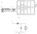
- FIG. 1 is an architecture of a zero-power communication system 100 applicable to some embodiments of the present disclosure.
- the architecture shown in FIG. 1 includes communication devices such as a network device 110 and a terminal 120.
- the network device 110 communicates with the terminal device 120.
- the network device 110 provides communication coverage for a specific geographical area and communicates with the terminal device 120 located in the coverage area.
- the network device 110 is configured to send a wireless power supply signal to the terminal 120 to supply power to the terminal. Accordingly, the terminal 120 sends data to the network device 110 or other communication devices through a backscattered signal.
- the above-mentioned wireless power supply signal also carries data or controls information from the network device 110 to the terminal 120.
- the above-mentioned wireless power supply signal is also used only for power supply, which is not limited in the embodiments of the present disclosure.
- the technical solutions of the embodiments of the present disclosure are applied to various communication systems, such as: the 5th generation (5G) system or new radio (NR), long term evolution (LTE) system, LTE frequency division duplex (FDD) system, LTE time division duplex (TDD), cellular Internet of Things, Wi-Fi communication system, etc.
- 5G 5th generation
- NR new radio
- LTE long term evolution
- FDD frequency division duplex
- TDD LTE time division duplex
- cellular Internet of Things such as Wi-Fi communication system, etc.
- the terminal in the embodiments of the present disclosure is also referred to as user equipment (UE), access terminal, user unit, user station, mobile station (MS), mobile terminal (MT), remote station, remote terminal, mobile device, user terminal, terminal device, wireless communication device, user agent or user device.
- the terminal device in the embodiments of the present disclosure provides voice and/or data connectivity to a user, and is configured to connect people, objects, and machines, such as household appliances, sensors, electronic tags with wireless connection functions, etc.
- Electronic tags are also referred to as "radio frequency tags”. In radio frequency identification (RFID) technology, electronic tags are also referred to as "RFID tags”.
- RFID radio frequency identification
- the network device in the embodiments of the present disclosure is a device for communicating with a terminal device. If the terminal is an electronic tag, the network device is a reader/writer for reading and writing the electronic tag.
- the reader/writer is a reader/writer based on RFID technology, for example.
- the network device and the terminal device may be deployed on land, including indoors or outdoors, handheld or vehicle-mounted; they may also be deployed on the water surface; they may also be deployed on aircraft, balloons, and satellites in the air.
- the embodiments of the present disclosure do not limit the scenarios in which the network device and terminal device are located.
- the terminal is an electronic tag and the network device is a reader/writer.
- the electronic tag is composed of a coupling component and a chip. Each electronic tag has a unique electronic code.
- the electronic tag is placed on a target to be detected to achieve the purpose of marking the target object.
- the reader/writer can not only read the information on the electronic tag, but also write the information on the electronic tag.
- the reader/writer provides the electronic tag with the energy required for communication. After the electronic tag enters the electromagnetic field, it receives the radio frequency signal emitted by the reader/writer.
- the electronic tag uses the energy obtained from the electromagnetic field generated in the space to transmit the information stored in the electronic tag.
- the reader/writer reads the information and decodes it to identify the electronic tag.
- the energy harvesting module 121 is configured for power harvesting.
- the harvested energy includes various forms of energy such as radio waves, solar energy, light energy, thermal energy, mechanical energy, etc.
- the energy harvested by the energy harvesting module 121 is configured to drive the device to work, thereby achieving battery-free operation.
- energy is harvested through a wireless power supply signal sent by a network device.
- the wireless power supply signal is a radio frequency signal (RF) transmitted by a network device. Therefore, the energy harvesting module is also referred to as a "radio frequency energy harvesting module” (abbreviated as "RF module”).
- RF module radio frequency energy harvesting module
- FIG. 2 shows a structure of the energy harvesting module.
- the energy harvesting module may harvest electromagnetic wave energy in space through electromagnetic induction, thereby driving the load circuit (including low-power computing, sensors, etc.).
- the energy harvesting module shown in FIG. 2 is an RF module.
- the energy harvesting module 121 stores the harvested energy in a capacitor C, which is the charging process of the capacitor C. When the charging process of the capacitor C is completed, the capacitor C starts to discharge to provide energy for the terminal's operation.
- a transport (TX) path of the network device 110 is provided with other devices for processing the signal to be sent, such as an amplifier (AMP), etc.
- a receive (RX) path of the network device 110 is provided with other devices for processing the received signal, such as a low noise amplifier (LNA), etc.
- LNA low noise amplifier
- the terminal 120 is provided with an energy harvesting unit for harvesting energy from a wireless power supply signal from the network device.
- the terminal 120 is also provided with a low-power processing module (e.g., a logic processing unit as shown in FIG. 3 ) to perform corresponding computing functions.
- the terminal 120 does not actively transmit signals, that is, backscattering communication is achieved by modulating the incoming signal. Secondly, the terminal 120 does not rely on the active power amplifier transmitter in the related art, and uses a low-power computing unit, thereby greatly reducing the hardware complexity. In addition, in backscattering communication, the terminal 120 combines energy harvesting to achieve battery-free communication.
- FIG. 3 only exemplarily shows a connection structure of a signal processing circuit, and the processing circuit of the network device 110 and/or the terminal 120 may include other components, which is not specifically limited in the embodiments of the present disclosure.
- FIG. 4 shows a circuit diagram of a terminal based on resistance load modulation technology. It should be noted that the circuit shown in FIG. 4 implements the load modulation technology in a manner similar to the implementation of the existing circuit for implementing the load modulation technology. For the sake of simplicity, the functions of the resistor R 2 , the load R L , the capacitors C 1 , C 2 , and the inductors L 1 , L 2 shown in FIG. 4 are not repeated.
- a resistor R 3 is connected in parallel to the load.
- the switch S is controlled based on the binary data stream to realize the connection or disconnection of the resistor R 3 .
- the connection and disconnection of the resistor R 3 cause the change of the circuit voltage, and the change of the circuit voltage controls the amplitude of the backscattered signal of the terminal, thereby realizing the modulation of the backscattered signal, that is, performing amplitude-shift keying (ASK) modulation on the backscattered signal.
- ASK amplitude-shift keying
- the data transmitted by the terminal is represented by different encoding methods to represent binary "1" and "0".
- encoding methods in zero-power communication technology include non-return zero (NRZ) encoding, Manchester encoding, unipolar RZ encoding, differential binary phase (DBP) encoding, Miller encoding, differential encoding, etc.
- NRZ non-return zero
- DBP differential binary phase
- Miller encoding Miller encoding
- differential encoding etc.
- different pulse signals may be used to represent "1" and "0".
- the terminal uses load modulation to modulate the incoming signal (i.e., the signal sent by the network device) to achieve the backscattering communication process. Therefore, the terminal in backscattering communication usually has the following advantages.
- the first advantage is that since the terminal does not need to actively transmit signals, there is no need to construct a complex RF path.
- the RF path does not need to include devices such as power amplifiers (PA) and RF filters, thereby reducing the cost and size of the terminal.
- PA power amplifiers
- the second advantage is that since the terminal does not need to actively generate high-frequency signals, a high-frequency crystal oscillator is not required, thereby reducing the cost and size of the terminal.
- the third advantage is that since the terminal may use the backscattering technology to communicate with the network device, the terminal consumes less energy during communication and does not even need to consume its own energy.
- zero-power terminals consume very little energy for communication, or even no energy at all. Therefore, in zero-power communication technology, terminals are divided into three categories based on their energy sources and energy usage: passive zero-power terminals, semi-passive zero-power terminals, and active zero-power terminals.
- Passive zero-power terminals usually do not need built-in batteries.
- the terminal When the terminal is close to the network device, it is in the near field formed by the antenna radiation of the network device. At this time, the antenna of the terminal generates an induced current through electromagnetic induction, which powers the terminal to achieve demodulation of the received signal and/or modulation and encoding of the signal to be transmitted.
- the passive zero-power terminal is an electronic tag (i.e., a passive electronic tag).
- the network device is a reader/writer of the electronic tag, which is used to read the content in the electronic tag and/or to change the content in the electronic tag.
- the passive electronic tag is close to the reader/writer, the electronic tag is in the near field formed by the antenna radiation of the reader/writer, and the antenna of the electronic tag generates an induced current through electromagnetic induction, and the induced current drives the chip circuit of the electronic tag.
- the chip circuit sends the identification information stored in the tag to the reader/writer through the electronic tag antenna.
- the passive zero-power terminal does not require a built-in battery to drive either the forward link or the backward link, and is a true zero-power terminal.
- the semi-passive zero-power terminal itself does not install a conventional battery, but uses the energy harvesting module 121 to harvest radio wave energy and stores the harvested energy in an energy storage unit (such as a capacitor). After the energy storage unit obtains energy, it supplies energy to the terminal to realize the demodulation of the received signal and/or the modulation and encoding of the signal to be transmitted.
- the semi-passive zero-power terminal inherits the advantages of the passive zero-power device, such as small size, light weight, low price, and long service life.
- the semi-passive zero-power device is an electronic tag (i.e., a semi-active electronic tag).
- the network device is a reader/writer of the electronic tag.
- the built-in battery of the semi-active electronic tag only provides power for a small number of circuits in the chip.
- the built-in battery supplies power to the chip (e.g., an RFID chip) to increase the reading and writing distance of the electronic tag and improve the reliability of communication.
- the semi-passive zero-power terminal does not require a built-in battery to drive either the forward link or the backward link. Although energy stored in capacitors is used during operation, the energy comes from the radio energy harvested by the energy harvesting module. Therefore, it is also a true zero-power terminal.
- Active zero-power terminals may have built-in batteries.
- the batteries are used to drive the low-power chip circuits of the zero-power terminals, thereby achieving demodulation of forward link signals and modulation of backward link signals.
- zero-power terminals use backscattering to transmit signals. Therefore, the zero-power consumption of this type of terminal is mainly reflected in the fact that the signal transmission of the backward link does not require the terminal's own power, but uses backscattering.
- Zero-power devices with built-in batteries including active zero-power terminals and semi-passive zero-power terminals are used.
- Unlicensed spectrum is a spectrum that is used for radio device communication.
- Unlicensed spectrum is considered as shared spectrum, that is, communication devices in different communication systems use the spectrum as long as they meet the regulatory requirements set by the country or region on the spectrum, without applying for exclusive spectrum authorization from the government.
- Unlicensed spectrum is also referred to as non-licensed spectrum.
- Wi-Fi communication systems Currently, systems that use unlicensed spectrum for communication include Wi-Fi communication systems, NR-U communication systems in 3GPP, etc.
- Channel sensing (or channel monitoring) is a key technology in the LBT principle. Based on the channel sensing principle, the communication device performs LBT on the carrier of the unlicensed spectrum after the service arrives, and starts sending signals on the carrier after the LBT is successful. Different communication systems using unlicensed spectrum use different channel sensing technologies, and different channel sensing technologies must meet regulatory requirements to ensure fairness for each communication system when using the unlicensed spectrum. The following takes the Wi-Fi communication system as an example to introduce channel sensing in detail.
- channel sensing adopts the carrier sensing mechanism.
- the carrier sensing mechanism is divided into physical carrier sensing and virtual carrier sensing. Physical carrier sensing and virtual carrier sensing correspond to an indicator respectively. If any indicator indicates that the channel is busy, the channel is busy and the signal cannot be sent using the channel.
- Physical carrier sensing adopts the following three channel idle detection methods: energy detection (ED), carrier sense (CS) and energy detection & carrier sense (ED & CS). These detection methods are collectively referred to as clear channel assessment (CCA). The above three detection methods will be explained below.
- the energy level of the signal received on the channel is determined.
- a first threshold for example, the threshold ED_threshold specified by the physical layer
- the channel is considered occupied.
- the power of the received signal is less than the first threshold, the channel is considered idle.
- the setting of the first threshold is related to the transmit power of the signal.
- Carrier sense is also referred to as carrier monitoring.
- the carrier sense method determines whether the channel is idle by identifying a certain part of the data frame. Taking the 802.11 standard as an example, the preamble part in the physical layer convergence protocol (PLCP) header of the 802.11 data frame is identified. The preamble is described in detail in conjunction with FIGS. 5 and 6 below, and is not repeated here.
- the preamble in 802.11 is constructed using a specific sequence. The sequence is known to both the transmitter and the receiver and is used for frame synchronization and symbol synchronization. In the actual monitoring process, the node continuously samples the channel signal and uses the preamble for correlation operation.
- the correlation operation includes autocorrelation operation and cross-correlation operation.
- Autocorrelation operation is often performed in the technology based on orthogonal frequency division multiplexing (OFDM) (such as the 802.11a standard).
- Cross-correlation operation is often performed in the technology based on direct sequence spread spectrum (DSSS) (such as the 802.11b standard).
- DSSS direct sequence spread spectrum
- the result of the correlation calculation is compared with a second threshold. If the result is greater than the second threshold, it is considered that a signal of the channel is detected, that is, the channel is occupied. If the result is less than the second threshold, it is considered that no signal of the channel is detected, that is, the channel is idle.
- the detection technology used is determined according to the technology used in the specific physical layer. For example, DSSS technology combines energy detection and carrier sense. Frequency-hopping spread spectrum (FHSS) technology only uses carrier sense technology. In hybrid detection, if any detection result is detected to be out of limit, it is considered that the channel is occupied.
- FHSS Frequency-hopping spread spectrum
- FIG. 5 and FIG. 6 are exemplary diagrams of a data frame including a preamble.
- the PPDU frame includes a physical layer header.
- STF is composed of 10 short symbols (for example, symbols t1 -t10). Each short symbol is 0.8us.
- STF a plurality of functions are realized. For example, through STF, frame synchronization and coarse frequency synchronization are realized. Based on symbols t1-t7, the main functions that are realized are signal detection, automatic gain control (AGC), and diversity selection. Based on symbols t8-t10, the main functions that are realized are coarse frequency synchronization, offset estimation, and timing synchronization.
- the first part of the physical layer header is a preamble.
- the preamble includes two parts, a synchronization part (sync) and a start of frame delimiter (SFD).
- Sync is configured to achieve frame synchronization.
- SFD is used as a start of frame identifier.
- PPDU also includes a physical service data unit (PSDU) or a message protocol data unit (MPDU).
- PSDU physical service data unit
- MPDU message protocol data unit
- unlicensed spectrum is used for free, saving the expense of purchasing spectrum and saving operating costs.
- the unlicensed devices have a large user, such as a large number of widely deployed Wi-Fi devices in homes, enterprises, shopping malls, etc., which makes it easy to promote and deploy zero-power communication systems.
- the terminal does not send a preamble when performing backscattering communication in the unlicensed frequency band
- other Wi-Fi devices in the Wi-Fi system cannot detect that the channel is used by detecting the preamble, and may also use the channel for data transmission, thereby generating interference on the channel.
- the method shown in FIG. 7 is executed by a terminal and a Wi-Fi device.
- the terminal is a device capable of performing backscattering communication.
- the terminal is a zero-power terminal.
- the naming of the zero-power terminal does not restrict the source and use of its energy.
- the energy required for the operation of the zero-power terminal may come from the external environment.
- the zero-power terminal is zero-power or low-power.
- the energy required for the operation of the zero-power terminal may come from the power supply of the terminal itself.
- the zero-power terminal is a low-power terminal.
- the definition of a zero-power terminal mainly includes features such as low complexity, support for environmental power supply, backscattering, and new waveforms.
- the name of the zero-power terminal is not unique, and it may also be other names, such as an environmentally powered terminal, a terminal based on energy harvesting, and the like.
- step S710 the Wi-Fi device sends a first signal on a first channel.
- the first channel is any channel that meets the conditions in the frequency domain resources.
- the first channel belongs to a channel in an unlicensed frequency band. After occupying the first channel, the Wi-Fi device sends the first signal on the first channel.
- the first signal includes a first preamble and/or a first carrier.
- the first preamble is a preamble included in the data frame of the Wi-Fi system described above.
- the first preamble is a preamble part in a PLCP header that meets the 802.11 standard.
- the first preamble includes one or more of STF, LTF, and other signals.
- the first preamble is generated by the terminal with the help of the Wi-Fi device.
- the information carried in the first preamble is set according to the needs of the terminal. For example, the information such as the duration of occupying the channel contained in the first preamble is set based on the needs of the terminal, and is not set based on the needs of the Wi-Fi device.
- the first preamble is consistent with the preamble part for implementing carrier sense in the Wi-Fi system. That is, channel sensing is implemented based on the first preamble. When other Wi-Fi devices detect the first preamble, they know that the first channel for transmitting the first preamble is occupied, and thus do not send data on the first channel.
- the first signal is used to be backscattered by the terminal. That is, the method shown in FIG. 7 includes step S720, in which the terminal backscatters the first signal on the first channel.
- the terminal backscatters the first signal including the first preamble on the first channel. It can be understood that even when the terminal cannot generate the preamble by itself, the terminal backscatters the first signal including the first preamble to enable the terminal to send the first preamble. For example, before sending data, the terminal backscatters the first preamble on the first channel.
- the terminal may know that the first channel is occupied, that is, they will not transmit data on the first channel, thereby avoiding conflicts.
- the first carrier occupies part of the frequency domain resources in the first channel.
- the first carrier occupies a frequency point or a frequency domain resource within a range in the first channel.
- the present disclosure does not limit the waveform of the first carrier.
- the first carrier is a sine wave.
- the terminal modulates the first carrier and transmits data by backscattering based on the first carrier.
- the terminal based on the first carrier, other devices supporting unlicensed frequency band communication (such as Wi-Fi devices) detects that the first channel is occupied by energy detection, so that data will not be transmitted on the first channel, thereby avoiding conflicts.
- Wi-Fi devices determine that the first channel is occupied by detecting the first preamble based on the carrier sense method, and/or other Wi-Fi devices determine that the first channel is occupied by detecting the first carrier based on the energy detection method, thereby avoiding the situation where other Wi-Fi devices also occupy the first channel.
- the first signal is transmitted over the first frequency domain resources. That is, the Wi-Fi device sends the first signal over the first frequency domain resources.
- the first frequency domain resources are all frequency domain resources of the first channel.
- the first frequency domain resources are all available frequency domain resources of the first channel.
- the available frequency domain resources are frequency domain resources in the first channel that are available for communication devices to communicate.
- the first channel includes available frequency domain resources and protected frequency domain resources.
- the protected frequency domain resources are used to avoid interference from other channels.
- the protected frequency domain resources are reserved.
- the protected frequency domain resources are located at the edge of the first channel.
- the protected frequency domain resources are generally not available for use by communication devices.
- the available resources are frequency domain resources in the first channel other than the protected frequency domain resources.
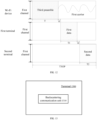
- FIG. 8 shows the first channels occupied by the Wi-Fi device and the terminal separately. In fact, the first channels occupied by the Wi-Fi device and the terminal may overlap.
- the first carrier occupies part or all of the first frequency domain resources, and the present disclosure does not limit this.
- the first carrier occupies a frequency point in the first frequency domain resources.
- the first signal includes a first preamble, and the first signal is transmitted on part of the frequency domain resources of the first channel.
- the first signal is transmitted on a second sub-band. That is, the Wi-Fi device sends the first signal to the terminal on the second sub-band.
- the second sub-band is part of the frequency domain resources in the first channel.
- a sub-band may also be referred to as a sub-channel.
- the terminal backscatters the first preamble on the first sub-band.
- the first sub-band is a frequency domain resource different from the second sub-band in the first channel. That is, the frequencies occupied by the Wi-Fi device and the terminal for sending the first preamble are different.
- the first sub-band is part of the frequency domain resources in the first channel.
- the first sub-band is part of the frequency domain resources in the first channel.
- the second sub-band is part or all of the frequency domain resources in the first channel except the first sub-band.
- the first preamble is transmitted on a part of the frequency domain resources of the first channel, and the terminal backscatters the first preamble on another part of the frequency domain resources on the first channel.
- the Wi-Fi device and the terminal each occupy half of the frequency domain resources of the first channel.
- the width of the first channel is 2 MHz.
- the first preamble transmitted by the Wi-Fi device and the first preamble backscattered by the terminal respectively occupy the upper and lower 1 MHz sub-channels of the first channel.
- FIG. 9 is a schematic diagram of resources for transmitting a first signal and resources for backscattering the first signal according to some embodiments of the present disclosure.
- the Wi-Fi device After the Wi-Fi device occupies the first channel, before the terminal transmits data, the Wi-Fi device generates a first preamble for the terminal.
- the Wi-Fi device sends the first preamble to the terminal on the second sub-band.
- the terminal sends the first preamble on the first sub-band by backscattering. That is, in FIG. 9 , the Wi-Fi device and the terminal occupy different frequency domain resources of the first channel to send the first preamble.
- the Wi-Fi device sends a first carrier. Based on the first carrier, the terminal transmits data on the first sub-band by backscattering.
- the first carrier is located in frequency domain resources other than the first sub-band in the first channel. For example, the first carrier is located in the second sub-band. It can be understood that the data signal transmitted by the terminal by backscattering is located on a different frequency domain resource of the same channel as the first carrier transmitted by the Wi-Fi device.
- the first carrier may not occupy all frequency domain resources of the second sub-band.
- the first carrier occupies a frequency point in the second carrier.
- the frequency domain resources used by the Wi-Fi device to send the first preamble are different from the frequency domain resources used by the terminal to backscatter the first preamble, which reduces interference between the signal transmitted by the Wi-Fi device and the signal transmitted by the terminal device.
- the Wi-Fi device also sends a second signal on the first sub-band.
- the second signal includes the first preamble. That is, the Wi-Fi device repeatedly sends the first preamble in two different sub-bands of the first channel.
- the terminal backscatters the first preamble in any sub-band of the first sub-band or the second sub-band. For example, the terminal backscatters the first preamble on the first sub-band based on the first preamble transmitted in the first sub-band. Alternatively, the terminal backscatters the first preamble on the first sub-band based on the first preamble transmitted in the second sub-band.
- the Wi-Fi device repeatedly sends the first preamble in different parts of the first channel (such as the first sub-band and the second sub-band). This allows the Wi-Fi device to transmit the first preamble at a higher transmit power, so that other Wi-Fi devices within a larger range can detect that the first channel is occupied by the Wi-Fi device, thereby avoiding other Wi-Fi devices from occupying the channel during the backscattering communication of the terminal. For example, it can avoid the situation where other Wi-Fi devices at a long distance cannot detect that the first channel is occupied due to the low transmit power of the terminal during backscattering.
- the Wi-Fi device For the case where the Wi-Fi device occupies part of the first channel to send the first preamble, the Wi-Fi device sends the second preamble on all frequency domain resources or all available frequency domain resources of the first channel. Since the frequency domain resources occupied by the second preamble are wider than the frequency domain resources occupied by the first preamble, the second preamble may also be referred to as a broadband preamble.
- the sub-band is narrower than the first channel. If the terminal backscatters the first preamble on a certain sub-band, the first preamble is suitable for other Wi-Fi devices working on a channel narrower than the first channel, so that these Wi-Fi devices can find that the narrower channel (such as the first sub-band or the second sub-band) is already occupied.
- the second preamble may occupy the bandwidth of the entire first channel, so that the second preamble is suitable for other Wi-Fi devices that expect to work on the complete first channel, so that these Wi-Fi devices find that the entire first channel is occupied.
- the terminal occupies the first sub-band in the first channel
- the Wi-Fi device occupies the second sub-band in the first channel.
- the width of the first channel is 2 MHz
- the first sub-band and the second sub-band are upper and lower 1 MHz sub-channels of the first channel, respectively.
- the second preamble transmitted by the Wi-Fi device occupies the entire first channel. Therefore, the second preamble is used for carrier sensing of the first channel by other Wi-Fi devices that expect to work on the 2 MHz first channel.
- the first preamble transmitted by the Wi-Fi device and the first preamble backscattered by the terminal occupies the upper and lower 1 MHz sub-channels of the first channel, respectively, and are used for carrier sensing of these sub-bands by other Wi-Fi devices that expect to work on the first sub-band and/or the second sub-band.
- the Wi-Fi device sends first indication information to the terminal.
- the first indication information instructs the terminal to backscatter the first signal.
- the first channel is obtained by the Wi-Fi device in an unlicensed frequency band.
- the Wi-Fi device obtains the first channel, for example, by LBT.
- the Wi-Fi device sends a third preamble to allow other Wi-Fi devices to know that the first channel is occupied.
- the Wi-Fi device shares the first channel with the terminal through the first indication information to instruct the terminal to perform backscattering on the first channel. For example, after obtaining the first channel, the Wi-Fi device sends an indication of channel occupancy of the first channel and shares the resources of the occupied first channel with the terminal for backscattering communication.
- the present disclosure does not limit the manner in which the Wi-Fi device shares the resources of the first channel.
- the Wi-Fi device shares the duration of occupying the first channel with the terminal.
- the Wi-Fi device also shares the acquired first channel with a plurality of terminals.
- the plurality of terminals may occupy the first channel for backscattering communication.
- the Wi-Fi device sends corresponding first indication information to the plurality of terminals respectively to indicate the allocation of the first channel.
- the backscattering unit 1310 is configured to backscatter a first signal on a first channel.
- the first signal includes a first preamble and/or a first carrier, and the first signal is sent by a Wi-Fi device.
- the first carrier is located in frequency domain resources, other than the first sub-band, in the first channel.
- the first channel is a channel obtained by the Wi-Fi device in an unlicensed frequency band.
- the first indication information includes a first transmission duration and/or a first start time.
- the first transmission duration is the transmission duration during which the terminal is capable of occupying the first channel
- the first start time is a start time when the terminal is capable of occupying the first channel.
- the first transmission duration is part of a total duration indicated by a contention transmission opportunity (TXOP) occupied by the Wi-Fi device.
- TXOP contention transmission opportunity
- the first transmission duration is all or part of the total duration except a duration occupied by the Wi-Fi device for communication.
- a time interval between a start time of backscattering communication of the terminal and an end time of communication of the Wi-Fi device is less than or equal to a first threshold.
- the first threshold is 16 microseconds.
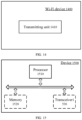
- FIG. 14 is a schematic structural diagram of a Wi-Fi device 1400 according to some embodiments of the present disclosure.
- the Wi-Fi device 1400 includes a sending unit 1410.
- the sending unit 1410 is configured to send a first signal on a first channel.
- the first signal includes a first preamble and/or a first carrier, and the first signal is used to be backscattered by a terminal.
- the first signal includes the first preamble
- the first signal is used to be backscattered by the terminal over first frequency domain resources
- the first frequency domain resources include all frequency domain resources or all available frequency domain resources of the first channel.
- the first signal occupies the first frequency domain resources for transmission.
- the first carrier is used for the terminal to transmit data over the first frequency domain resources by backscattering.
- the first signal is used to be backscattered by the terminal on a first sub-band.
- the first sub-band is part of the frequency domain resources in the first channel.
- the first signal is transmitted on a second sub-band, and the second sub-band is part or all of the frequency domain resources, except the first sub-band, in the first channel.
- the Wi-Fi device 1400 is further configured to send a second signal on the first sub-band.
- the second signal includes the first preamble.
- the first carrier is used for the terminal to transmit data on the first sub-band by backscattering.
- the first carrier is located in frequency domain resources other than the first sub-band in the first channel.
- the Wi-Fi device 1400 is further configured to send a second preamble over all frequency domain resources or all available frequency domain resources of the first channel.
- the first preamble includes a short training field (STF) and/or a long training field (LTF).
- STF short training field
- LTF long training field
- the Wi-Fi device 1400 is further configured to send first indication information to the terminal.
- the first indication information instructs the terminal to backscatter the first signal.
- the first channel is a channel obtained by the Wi-Fi device in an unlicensed frequency band.
- the first indication information includes a first transmission duration and/or a first start time.
- the first transmission duration is the transmission duration during which the terminal is capable of occupying the first channel
- the first start time is a start time when the terminal is capable of occupying the first channel.
- the first transmission duration is part of a total duration indicated by a contention transmission opportunity (TXOP) occupied by the Wi-Fi device.
- TXOP contention transmission opportunity
- the first transmission duration is all or part of the total duration except a duration occupied by the Wi-Fi device for communication.
- a time interval between a start time of backscattering communication of the terminal and an end time of communication of the Wi-Fi device is less than or equal to a first threshold.
- the first threshold is 16 microseconds.
- the device 1500 includes one or more processors 1510.
- the processor 1510 supports the device 1500 to implement the method described in the above method embodiments.
- the processor 1510 is a general-purpose processor or a special-purpose processor.
- the processor is a central processing unit (CPU).
- the processor is other general-purpose processors, digital signal processors (DSP), application specific integrated circuits (ASIC), field programmable gate arrays (FPGA) or other programmable logic devices, discrete gate or transistor logic devices, discrete hardware components, etc.
- DSP digital signal processors
- ASIC application specific integrated circuits
- FPGA field programmable gate arrays
- a general-purpose processor is a microprocessor or the processor is any conventional processor, etc.
- the device 1500 further includes a transceiver 1530.
- the processor 1510 communicates with other devices or chips through the transceiver 1530.
- the processor 1510 transmits and receives data with other devices or chips through the transceiver 1530.
- Some embodiments of the present disclosure also provide a computer-readable storage medium for storing one or more programs.
- the computer-readable storage medium is applicable to a terminal or network device according to the present disclosure, and the one or more programs, when loaded and run by a computer, cause the computer to carry out the method performed by the terminal or network device in the embodiments of the present disclosure.
- Some embodiments of the present disclosure also provide a computer program.
- the computer program is applicable to the terminal or network device according to the embodiments of the present disclosure, and the computer program, when loaded and run by a computer, causes the computer to carry out the method performed by the terminal or network device in the embodiments of the present disclosure.
- the "indication" mentioned may be a direct indication, an indirect indication, or an indication of an association relationship.
- a indicates B which can mean that A directly indicates B, for example, B may be obtained through A; it may also mean that A indirectly indicates B, for example, A indicates C, B may be obtained through C; it may also mean that there is an association relationship between A and B.
- the "protocol” refers to a standard protocol in the communication field.
- it may include an LTE protocol, an NR protocol, and related protocols used in future communication systems, and the present disclosure does not limit this.
- the term "and/or" is only a description of the association relationship of the associated objects, indicating that there may be three relationships.
- a and/or B can represent: A exists alone, A and B exist at the same time, and B exists alone.
- the character "/" in this article generally indicates that the associated objects before and after are in an "or" relationship.
- serial numbers of the above-mentioned processes does not mean the order of execution.
- the execution order of each process should be determined by its function and internal logic, and should not constitute any limitation on the implementation process of the embodiments of the present disclosure.
- the units described as separate components may or may not be physically separated, and the components shown as units may or may not be physical units, that is, they may be located in one place or distributed on a plurality of network units. Some or all of the units may be selected according to actual needs to achieve the purpose of the solution of this embodiment.
- each functional unit in each embodiment of the present disclosure may be integrated into one processing unit, or each unit may exist physically separately, or two or more units may be integrated into one unit.
- the computer program product includes one or more computer instructions.
- the computer may be a general-purpose computer, a special-purpose computer, a computer network, or other programmable device.
- the computer instructions may be stored in a computer-readable storage medium, or transmitted from one computer-readable storage medium to another computer-readable storage medium.
- the computer instructions may be transmitted from a website site, computer, server or data center by wired (e.g., coaxial cable, optical fiber, digital subscriber line (DSL)) or wireless (e.g., infrared, wireless, microwave, etc.) mode to another website site, computer, server or data center.
- the computer-readable storage medium may be any available medium that may be read by a computer or a data storage device such as a server or data center that includes one or more available media integrated.
- the available medium may be a magnetic medium (e.g., a floppy disk, a hard disk, a magnetic tape), an optical medium (e.g., a digital versatile disk (DVD)), or a semiconductor medium (e.g., a solid state drive (SSD)).
- a magnetic medium e.g., a floppy disk, a hard disk, a magnetic tape
- an optical medium e.g., a digital versatile disk (DVD)
- DVD digital versatile disk
- SSD solid state drive
Landscapes
- Engineering & Computer Science (AREA)
- Computer Networks & Wireless Communication (AREA)
- Signal Processing (AREA)
- Mobile Radio Communication Systems (AREA)
Applications Claiming Priority (1)
| Application Number | Priority Date | Filing Date | Title |
|---|---|---|---|
| PCT/CN2022/089169 WO2023206052A1 (zh) | 2022-04-26 | 2022-04-26 | 通信方法、终端以及wifi设备 |
Publications (2)
| Publication Number | Publication Date |
|---|---|
| EP4518440A1 true EP4518440A1 (de) | 2025-03-05 |
| EP4518440A4 EP4518440A4 (de) | 2026-03-04 |
Family
ID=88516432
Family Applications (1)
| Application Number | Title | Priority Date | Filing Date |
|---|---|---|---|
| EP22938909.3A Pending EP4518440A4 (de) | 2022-04-26 | 2022-04-26 | Kommunikationsverfahren, endgerät und wifi-vorrichtung |
Country Status (5)
| Country | Link |
|---|---|
| US (1) | US20250063555A1 (de) |
| EP (1) | EP4518440A4 (de) |
| CN (1) | CN119138029A (de) |
| MX (1) | MX2024013254A (de) |
| WO (1) | WO2023206052A1 (de) |
Families Citing this family (3)
| Publication number | Priority date | Publication date | Assignee | Title |
|---|---|---|---|---|
| WO2025217928A1 (zh) * | 2024-04-19 | 2025-10-23 | Oppo广东移动通信有限公司 | 通信方法、装置、设备、介质和程序产品 |
| WO2025231842A1 (zh) * | 2024-05-10 | 2025-11-13 | Oppo广东移动通信有限公司 | 无线通信的方法及通信设备 |
| WO2026076637A1 (zh) * | 2024-10-10 | 2026-04-16 | 北京小米移动软件有限公司 | 通信方法、通信设备及通信系统 |
Family Cites Families (8)
| Publication number | Priority date | Publication date | Assignee | Title |
|---|---|---|---|---|
| WO2018034439A1 (ko) * | 2016-08-16 | 2018-02-22 | 전자부품연구원 | 무선전력전송을 위한 백스캐터 의존 통신 방법 및 이를 위한 백스캐터 의존 통신 시스템 |
| EP3529902B1 (de) * | 2016-10-18 | 2021-06-09 | University of Washington | Rückstreusysteme, -vorrichtungen und -techniken unter verwendung von css-modulation und/oder kompensation von harmonischen höherer ordnung |
| EP3729754A1 (de) * | 2017-12-22 | 2020-10-28 | Telefonaktiebolaget LM Ericsson (publ) | System, netzwerkknoten, drahtlose vorrichtung, verfahren und computerprogramm für niedrigleistungs-backscatterbetrieb |
| WO2020159714A1 (en) * | 2019-01-30 | 2020-08-06 | Nec Laboratories America, Inc. | Tagging objects in indoor spaces using ambient, distributed backscatter |
| CN112087280B (zh) * | 2019-06-12 | 2025-01-10 | 华为技术有限公司 | 背反射通信方法及装置 |
| US11620462B2 (en) * | 2020-03-19 | 2023-04-04 | Nec Corporation | Reading passive wireless tags using commodity devices |
| US20210368439A1 (en) * | 2020-05-19 | 2021-11-25 | Qualcomm Incorporated | Wlan wake up radio with backscattering |
| CN114157346B (zh) * | 2022-02-08 | 2022-04-26 | 南京信息工程大学 | 协作式反向散射隐蔽通信系统及通信方法 |
-
2022
- 2022-04-26 WO PCT/CN2022/089169 patent/WO2023206052A1/zh not_active Ceased
- 2022-04-26 CN CN202280095124.5A patent/CN119138029A/zh active Pending
- 2022-04-26 EP EP22938909.3A patent/EP4518440A4/de active Pending
-
2024
- 2024-10-24 US US18/926,232 patent/US20250063555A1/en active Pending
- 2024-10-25 MX MX2024013254A patent/MX2024013254A/es unknown
Also Published As
| Publication number | Publication date |
|---|---|
| EP4518440A4 (de) | 2026-03-04 |
| WO2023206052A1 (zh) | 2023-11-02 |
| MX2024013254A (es) | 2024-12-06 |
| CN119138029A (zh) | 2024-12-13 |
| US20250063555A1 (en) | 2025-02-20 |
Similar Documents
| Publication | Publication Date | Title |
|---|---|---|
| US20250063555A1 (en) | Communication method, terminal and wifi device | |
| EP4496277A1 (de) | Drahtloskommunikationsverfahren und vorrichtungen | |
| US20250023589A1 (en) | Wireless communication method and device | |
| US20250039727A1 (en) | Communication method and communications apparatus | |
| US20250096979A1 (en) | Approaches for backscattering | |
| US20250096980A1 (en) | Approaches for backscattering | |
| US20250008497A1 (en) | Method for configuring resources, terminal, and network device | |
| WO2024050840A1 (zh) | 通信方法及通信装置 | |
| CN118805338A (zh) | 零功耗通信的方法、装置、设备及介质 | |
| EP4492894A1 (de) | Verfahren zur bestimmung einer zeitbereichsressource, endgerätevorrichtung und netzwerkvorrichtung | |
| CN105117744B (zh) | 一种采用超高频rfid读写器进行自组网通信的方法 | |
| KR101781743B1 (ko) | Wi-Fi 백스캐터 시스템 및 그것을 이용한 백스캐터 통신 방법 | |
| WO2023039730A1 (zh) | 通信方法、终端及网络设备 | |
| US20260025849A1 (en) | Wireless communication method and communication device | |
| EP4676130A1 (de) | Verfahren zur drahtlosen kommunikation sowie endgerätevorrichtung und netzwerkvorrichtung | |
| US20260012901A1 (en) | Wireless communication method, terminal device, and network device | |
| CN120224494A (zh) | 传输控制方法、装置、通信设备及存储介质 | |
| WO2024235108A1 (zh) | 传输控制方法、装置、通信设备及存储介质 | |
| WO2025231842A1 (zh) | 无线通信的方法及通信设备 | |
| WO2025227280A1 (zh) | 用于无线通信的方法及通信设备 | |
| WO2025150025A1 (en) | Configuring wireless devices for energy harvesting | |
| CN118921414A (zh) | 传输控制方法、装置、通信设备及存储介质 | |
| WO2026067259A1 (zh) | 一种通信方法及装置 | |
| WO2025156163A1 (zh) | 无线通信方法以及通信设备 | |
| WO2026030985A1 (zh) | 一种无线通信方法及装置、设备、芯片和存储介质 |
Legal Events
| Date | Code | Title | Description |
|---|---|---|---|
| STAA | Information on the status of an ep patent application or granted ep patent |
Free format text: STATUS: THE INTERNATIONAL PUBLICATION HAS BEEN MADE |
|
| PUAI | Public reference made under article 153(3) epc to a published international application that has entered the european phase |
Free format text: ORIGINAL CODE: 0009012 |
|
| STAA | Information on the status of an ep patent application or granted ep patent |
Free format text: STATUS: REQUEST FOR EXAMINATION WAS MADE |
|
| 17P | Request for examination filed |
Effective date: 20241125 |
|
| AK | Designated contracting states |
Kind code of ref document: A1 Designated state(s): AL AT BE BG CH CY CZ DE DK EE ES FI FR GB GR HR HU IE IS IT LI LT LU LV MC MK MT NL NO PL PT RO RS SE SI SK SM TR |
|
| DAV | Request for validation of the european patent (deleted) | ||
| DAX | Request for extension of the european patent (deleted) | ||
| A4 | Supplementary search report drawn up and despatched |
Effective date: 20260203 |
|
| RIC1 | Information provided on ipc code assigned before grant |
Ipc: H04W 52/02 20090101AFI20260128BHEP |