EP4518441A1 - Kommunikationsverfahren und kommunikationsvorrichtung - Google Patents
Kommunikationsverfahren und kommunikationsvorrichtung Download PDFInfo
- Publication number
- EP4518441A1 EP4518441A1 EP22939106.5A EP22939106A EP4518441A1 EP 4518441 A1 EP4518441 A1 EP 4518441A1 EP 22939106 A EP22939106 A EP 22939106A EP 4518441 A1 EP4518441 A1 EP 4518441A1
- Authority
- EP
- European Patent Office
- Prior art keywords
- information
- frame
- terminal device
- data
- field
- Prior art date
- Legal status (The legal status is an assumption and is not a legal conclusion. Google has not performed a legal analysis and makes no representation as to the accuracy of the status listed.)
- Pending
Links
Images


Classifications
-
- H—ELECTRICITY
- H04—ELECTRIC COMMUNICATION TECHNIQUE
- H04W—WIRELESS COMMUNICATION NETWORKS
- H04W52/00—Power management, e.g. Transmission Power Control [TPC] or power classes
- H04W52/02—Power saving arrangements
- H04W52/0209—Power saving arrangements in terminal devices
-
- Y—GENERAL TAGGING OF NEW TECHNOLOGICAL DEVELOPMENTS; GENERAL TAGGING OF CROSS-SECTIONAL TECHNOLOGIES SPANNING OVER SEVERAL SECTIONS OF THE IPC; TECHNICAL SUBJECTS COVERED BY FORMER USPC CROSS-REFERENCE ART COLLECTIONS [XRACs] AND DIGESTS
- Y02—TECHNOLOGIES OR APPLICATIONS FOR MITIGATION OR ADAPTATION AGAINST CLIMATE CHANGE
- Y02D—CLIMATE CHANGE MITIGATION TECHNOLOGIES IN INFORMATION AND COMMUNICATION TECHNOLOGIES [ICT], I.E. INFORMATION AND COMMUNICATION TECHNOLOGIES AIMING AT THE REDUCTION OF THEIR OWN ENERGY USE
- Y02D30/00—Reducing energy consumption in communication networks
- Y02D30/70—Reducing energy consumption in communication networks in wireless communication networks
Definitions
- This application relates to the field of communications technologies, and more specifically, to a communication method and a communications apparatus.
- a zero-power terminal is put into use in some communications systems, and the zero-power terminal has features such as low power consumption and low costs.
- the zero-power terminal has features such as low power consumption and low costs.
- design of the zero-power terminal is relatively simple, a problem may be introduced in a process of using the zero-power terminal.
- Embodiments of this application provide a communication method and a communications apparatus. Various aspects of embodiments in this application are described below.
- a communication method includes: transmitting, by a terminal device, first information to a network device, where the first information is used to indicate energy state information of the terminal device, energy corresponding to the energy state information is capable of being used by the terminal device to receive data, and the terminal device is a zero-power terminal device.
- a communication method includes: receiving, by a network device, first information transmitted by a terminal device, where the first information is used to indicate energy state information of the terminal device, energy corresponding to the energy state information is capable of being used by the terminal device to receive data, and the terminal device is a zero-power terminal device; and transmitting, by the network device, data to the terminal device based on the first information.
- a communications apparatus includes: a transmitting unit, configured to transmit first information to a network device, where the first information is used to indicate energy state information of the apparatus, energy corresponding to the energy state information is capable of being used by the apparatus to receive data, and the apparatus is a zero-power terminal device.
- a communications apparatus includes: a receiving unit, configured to receive first information transmitted by a terminal device, where the first information is used to indicate energy state information of the terminal device, energy corresponding to the energy state information is capable of being used by the terminal device to receive data, and the terminal device is a zero-power terminal device; and a transmitting unit, configured to transmit data to the terminal device based on the first information.
- a communications apparatus includes a memory, a transceiver, and a processor, where the memory is configured to store a program, the processor performs data transmission and receiving by using the transceiver, and the processor is configured to invoke the program in the memory to execute the method according to the first aspect.
- a communications apparatus includes a memory, a transceiver, and a processor, where the memory is configured to store a program, the processor performs data transmission and receiving by using the transceiver, and the processor is configured to invoke the program in the memory to execute the method according to the second aspect.
- a communications apparatus includes a processor, configured to invoke a program from a memory to execute the method according to the first aspect.
- a communications apparatus includes a processor, configured to invoke a program from a memory to execute the method according to the second aspect.
- a chip includes a processor, configured to invoke a program from a memory, to cause a device on which the chip is installed to perform the method according to the first aspect.
- a chip includes a processor, configured to invoke a program from a memory, to cause a device with the chip installed to perform the method according to the second aspect.
- a computer-readable storage medium stores a program, and the program causes a computer to execute the method according to the first aspect.
- a computer-readable storage medium stores a program, and the program causes a computer to execute the method according to the second aspect.
- a computer program product including a program, where the program causes a computer to execute the method according to the first aspect.
- a computer program product including a program, where the program causes a computer to execute the method according to the second aspect.
- a computer program is provided, where the computer program causes a computer to execute the method according to the first aspect.
- a computer program is provided, where the computer program causes a computer to execute the method according to the second aspect.
- a terminal device transmits energy state information to a network device, so that the network device can transmit data to the terminal device based on the energy state information. In this way, a case that data transmission fails due to insufficient current energy of the terminal device may be avoided, thereby improving communication efficiency.
- the wireless communications system may be integrated with an industrial wireless sensor network (industrial wireless sensor network, IWSN).
- IWSN industrial wireless sensor network
- a wireless communications system may be integrated with a smart logistics and smart warehousing.
- a wireless communications system may be integrated with an intelligent home network.
- a terminal device is generally required to have characteristics such as relatively low costs, a relatively small size (such as an ultra-thin size), maintenance-free, and long life. Therefore, to meet the foregoing condition, communication may be performed between a network device and a terminal device by using a zero-power communication technology.
- the terminal device may also be referred to as a "zero-power terminal device” or "zero-power device”.
- FIG. 1 shows an architecture of a zero-power communications system 100 to which an embodiment of this application is applicable.
- the structure shown in FIG. 1 includes a network device 110 and a terminal device 120.
- the network device 110 may be a device in communication with the terminal device 120.
- the network device 110 may provide communication coverage for a specific geographic area, and may communicate with the terminal device 120 located within the coverage.
- the network device 110 and the terminal device 120 may communicate with each other based on a backscatter (back scattering) communication technology.
- a signal used for backscatter communication is extremely important.
- the signal used for backscatter communication is a radio signal, such as a radio frequency signal.
- the signal used for backscatter communication may include, for example, an energy supply signal, a carrier signal, and the like.
- the network device 110 may transmit an energy supply signal to the terminal device 120, to supply energy to the terminal device.
- the terminal device 120 may transmit data to the network device 110 by using a carrier signal.
- the energy supply signal may further carry data or control information transmitted by the network device 110 to the terminal device 120.
- the energy supply signal may also be used only for energy supply. This is not limited in embodiments of this application.
- FIG. 1 exemplarily shows one network device and one terminal device.
- the communications system 100 may include a plurality of network devices, and another quantity of terminal devices may be included within coverage of each network device. This is not limited in embodiments of this application.
- the communications system 100 may further include another network entity such as a network controller or a mobility management entity. This is not limited in embodiments of this application.
- the terminal device in embodiments of this application may also be referred to as a user equipment (user equipment, UE), an access terminal, a subscriber unit, a subscriber station, a mobile, a mobile station (mobile station, MS), a mobile terminal (mobile Terminal, MT), a remote station, a remote terminal, a mobile device, a user terminal, a terminal, a wireless communications device, a user agent, or a user apparatus.
- the terminal device in embodiments of this application may refer to a device providing a user with voice and/or data connectivity and capable of connecting people, objects, and machines, such as a handheld device, a vehicle-mounted device, a home appliance, a sensor, or an electronic tag that has a wireless connection function.
- the terminal device in embodiments of this application may be a mobile phone (mobile phone), a tablet computer (Pad), a notebook computer, a palmtop computer, a mobile internet device (mobile internet device, MID), a wearable device, a virtual reality (virtual reality, VR) device, an augmented reality (augmented reality, AR) device, a wireless terminal in industrial control (industrial control), a wireless terminal in self-driving (self driving), a wireless terminal in remote medical surgery (remote medical surgery), a wireless terminal in a smart grid (smart grid), a wireless terminal in transportation safety (transportation safety), a wireless terminal in a smart city (smart city), a wireless terminal in a smart home (smart home), or the like. All terminal devices in embodiments of this application may be zero-power terminals.
- the network device in embodiments of this application may be a device configured to communicate with the terminal device.
- the network device may be a reader/writer (for example, a reader/writer based on a radio frequency identification (radio frequency identification, RFID) technology) that is configured to read from or write into the electronic tag.
- the network device may be alternatively an access network device or a radio access network device.
- the network device may be a base station.
- the network device in embodiments of this application may be a radio access network (radio access network, RAN) node (or device) that connects the terminal device to a wireless network.
- RAN radio access network
- the base station may broadly cover the following various names, or may be replaced with the following names, such as a NodeB, an evolved NodeB (evolved NodeB, eNB), a next generation NodeB (next generation NodeB, gNB), a relay station, an access point, a transmitting and receiving point (transmitting and receiving point, TRP), a transmitting point (transmitting point, TP), a master eNode MeNB, a secondary eNode SeNB, a multi-standard radio (MSR) node, a home base station, a network controller, an access node, a radio node, an access point (access point, AP), a transmission node, a transceiver node, a baseband unit (baseband unit, BBU), a remote radio unit (Remote Radio Unit, RRU), an active antenna unit (active antenna unit, AAU), a remote radio head (remote radio head, RRH), a central unit (central unit, CU),
- the base station may be a macro base station, a micro base station, a relay node, a donor node, or the like, or a combination thereof.
- the base station may be a communications module, a modem, or a chip disposed in the device or apparatus described above.
- the base station may be a mobile switching center, a device that functions as a base station in device-to-device (device-to-device, D2D), vehicle-to-everything (vehicle-to-everything, V2X), and machine-to-machine (machine-to-machine, M2M) communication, a network-side device in a 6G network, a device that functions as a base station in a future communications system, or the like.
- the base station may support networks with a same access technology or different access technologies. A specific technology and a specific device form used by the network device are not limited in embodiments of this application.
- the base station may be a fixed or mobile base station.
- a helicopter or an unmanned aerial vehicle may be configured to function as a mobile base station, and one or more cells may move depending on a location of the mobile base station.
- a helicopter or an unmanned aerial vehicle may be configured to serve as a device in communication with another base station.
- the network device in embodiments of this application may be a CU or a DU, or the network device includes a CU and a DU.
- the gNB may further include an AAU.
- the network device and the terminal device may be deployed on land, including being indoors or outdoors, handheld, or vehicle-mounted; may be deployed on a water surface; or may be deployed on a plane, a balloon, or a satellite in the air.
- a scenario in which the network device and the terminal device are located is not limited.
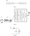
- the following describes a terminal device that supports the zero-power communication technology with reference to FIG. 2 .
- the terminal device 120 may include an energy harvesting module 121 and a backscatter communications module 122.
- the energy harvesting module 121 and the backscatter communications module 122 are described below with reference to FIG. 3 to FIG. 5 .
- the terminal device 120 may further include a low-power calculation module 123.
- the low-power calculation module 123 is configured to provide the terminal device 120 with a calculation function, for example, data processing.
- the terminal device 120 may further include a sensor 124, configured to collect external information (such as an ambient temperature and ambient humidity).
- the terminal device 120 may further include a memory 125, configured to store some information (for example, the external information collected by using the sensor or an object identifier).
- the energy harvesting module 121 is configured to harvest energy.
- energy may be harvested by using an energy supply signal transmitted by a network device.
- the energy supply signal may be a "radio frequency signal" transmitted by the network device. Therefore, the energy harvesting module is also referred to as a "radio frequency energy harvesting module”.
- FIG. 3 shows a possible structure of an energy harvesting module.
- the energy harvesting module 121 may harvest energy of a spatial electromagnetic wave of a radio frequency signal based on an electromagnetic induction principle, and store harvested energy in a capacitor C. This is a process of charging the capacitor C. After the charging process of the capacitor C ends, the capacitor C may start to discharge to supply energy to the terminal device for operation.
- the discharging of the capacitor C may be used to drive the terminal device to perform low-power demodulation on data transmitted by the network device.
- the discharging of the capacitor C may be used to drive a terminal to perform modulation on data to be transmitted.
- the discharging of the capacitor C may be used to drive a sensor of the terminal device to collect data.
- the discharging of the capacitor C may be used to drive the terminal device to read data in the memory 125, or the like.
- the backscatter communications module 122 is configured to perform backscatter communication between the terminal device 120 and the network device 110.
- a backscatter communication principle according to an embodiment of this application is described below with reference to FIG. 4 .
- the terminal device 120 receives a radio signal transmitted by the network device 110, and modulates the radio signal to load data that needs to be transmitted. Finally, a modulated signal is radiated from an antenna. This information transmission process is referred to as backscatter communication.
- the radio signal may also be referred to as a carrier signal.
- the carrier signal may be a radio signal that is not modulated.
- the carrier signal may be, for example, a sine wave signal.
- the backscatter communication is inseparable from a load modulation function.
- the load modulation function may be understood as that a circuit parameter of an oscillation loop of the terminal device is adjusted and controlled according to a beat of a data stream, such that parameters such as magnitude of impedance of the terminal device change accordingly, thereby completing a modulation process.
- another component may be further disposed on a transport (transport, TX) path of the network device 110.
- the component is configured to process a to-be-transmitted signal and may be, for example, an amplifier (amplifier, AMP).
- Another component may be further disposed on a receive (receive, RX) path of the network device 110.
- the component is configured to process a received signal and may be, for example, a low noise amplifier (low noise amplifier, LNA).
- the terminal device 120 may include an energy harvesting module, and the energy harvesting module may be configured to collect any signal in an environment.
- the energy harvesting module may be configured to harvest energy of an energy supply signal transmitted by a network device.
- a form of the energy supply signal is not specifically limited in embodiments of this application.
- the energy supply signal may be a modulated radio signal, or may be an unmodulated radio signal.
- the carrier signal described above may also be used as an energy supply signal.
- the power supply signal may also be a wireless signal of any waveform, such as a sine wave or a square wave.
- a logic processing module may be further disposed in the terminal device 120, to execute a corresponding calculation function.
- FIG. 4 only exemplarily shows a connection structure of a signal processing circuit.
- Processing circuits of the network device 110 and/or the terminal device 120 may include other components. This is not specifically limited in embodiments of this application.
- FIG. 5 shows a circuit diagram of a terminal device based on a resistive load modulation technology. It should be noted that a manner in which the circuit in FIG. 5 implements the load modulation technology is similar to a manner in which an existing circuit implements the load modulation technology. For brevity, functions of resistors R2 and R3, capacitors C1 and C2, and inductors L1 and L2 included in the circuit shown in FIG. 5 are not described again.
- a resistor RL may be connected in parallel to the load.
- the switch S may implement on/off of the resistor RL based on control of a binary data stream.
- on/off of the resistor RL causes a change in a voltage of the circuit, and the change in the voltage of the circuit may control an amplitude of a backscatter signal from the terminal device, so as to implement modulation of the backscatter signal, that is, amplitude-shift keying (amplitude-shift keying, ASK) modulation of the backscatter signal.
- amplitude-shift keying amplitude-shift keying, ASK
- on/off of a capacitor may be controlled based on a binary data stream, to change a resonance frequency of the circuit, thereby changing an operating frequency of the backscatter signal.
- frequency-shift keying frequency-shift keying, FSK
- the terminal device may perform information modulation on a received signal (namely, a carrier signal) in a manner of load modulation, to implement a backscatter communication process. Therefore, a terminal device in backscatter communication generally has the following advantages.
- a complex radio frequency path does not need to be constructed.
- components such as a power amplifier (power amplifier, PA) and a radio frequency filter may not be provided in the radio frequency path, so as to reduce costs and a volume of the terminal.
- the terminal device does not need to proactively generate a high-frequency signal, there is no need for a high-frequency crystal oscillator, so that costs and a volume of the terminal device are reduced.
- the terminal device may communicate with the network device by using a backscatter technology, energy consumed by the terminal device during communication is relatively low, and even energy of the terminal device does not need to be consumed.
- the terminal device may further have a coding function.
- Data transmitted by an encoding end (for example, a terminal device or an electronic tag) may be represented as binary "1" and "0" by using different forms of code.
- commonly used coding manners may include non-return-to-zero inverted (NRZ) encoding, Manchester (Manchester) encoding, unipolar return-to-zero (Unipolar RZ) encoding, differential bi-phase (DBP) encoding, Miller (Miller) encoding, differential encoding, and the like.
- NRZ non-return-to-zero inverted
- Manchester Manchester
- DBP differential bi-phase
- Miller (Miller) encoding Miller (Miller) encoding
- differential encoding and the like.
- an encoding process is to represent 0 and 1 by using different pulse signals.
- a terminal device in zero-power communication (also referred to as a "zero-power terminal device”) consumes little energy of the terminal device for communication, and may even not consume energy of the terminal device. Therefore, in the zero-power communication technology, terminal devices may be classified, based on an energy source and an energy use manner of the terminal devices, into three types: a passive zero-power terminal, a semi-passive zero-power terminal, and an active zero-power terminal.
- a battery usually does not need to be installed on the passive zero-power terminal.
- the terminal device When the terminal device approaches a network device, the terminal device is located within coverage of a near field formed by radiation of an antenna of the network device.
- the antenna of the terminal device may generate an induced current by using electromagnetic induction, and the induced current may supply energy to the terminal device, to implement demodulation of a received signal and/or modulation, encoding, and the like of a to-be-transmitted signal.
- the passive zero-power terminal may be an electronic tag.
- the network device may be a reader/writer in a radio frequency identification (RFID) system, and is configured to read content in the electronic tag and/or is configured to change the content in the electronic tag.
- RFID radio frequency identification
- radio wave energy may be harvested by using the energy harvesting module 121, and the harvested energy may be stored in an energy storage unit (such as a capacitor). After obtaining the energy, the energy storage unit may supply energy to the terminal device, so as to implement demodulation of a received signal, and/or modulation and encoding of a signal to be transmitted, and the like.
- the active zero-power terminal may have a built-in battery.
- the battery may supply energy to the terminal device, so as to implement demodulation of a received signal, and/or modulation and encoding of a signal to be transmitted, and the like.
- the terminal device performs communication by using a backscatter technology
- the terminal device does not need to consume energy of the battery. Therefore, for such a terminal device, "zero power" is mainly reflected in a scenario in which the terminal device performs communication by using the backscatter technology.
- the active zero-power terminal may also be supplied by a built-in battery, to increase a communication distance of the zero-power terminal and improve communication reliability.
- the active zero-power terminal may be an electronic tag
- the network device may be an RFID reader/writer.
- the built-in battery may supply power to an RFID chip in the terminal device, to increase a read/write distance between the RFID reader/writer and the electronic tag.
- the built-in battery may supply power to the RFID chip in the terminal device, so as to shorten a read/write delay of the RFID reader/writer on the electronic tag, thereby improving communication reliability.
- a zero-power terminal in embodiments of this application has features such as low complexity, supporting environmental energy supply, backscatter, and a new waveform.
- a name of the zero-power terminal in embodiments of this application does not constitute a limitation on an energy source and an energy usage manner of the terminal, provided that energy required for operation of the terminal mainly comes from an external environment.
- the terminal device may be a zero-power device or a low power device.
- the zero-power terminal may also be referred to as an environment energy-supplying terminal, an energy-harvesting-based terminal, or the like.
- a zero-power terminal is introduced to reduce power consumption and costs of the terminal.
- a zero-power terminal is introduced into a wireless fidelity (wireless fidelity, WiFi) communications system, to reduce power consumption and costs of WiFi communications devices.
- WiFi wireless fidelity
- FIG. 6 is a schematic diagram of a WiFi communications system according to an embodiment of this application.
- the system 600 shown in FIG. 6 includes an access point (access point, AP) 610 and stations (station, STA) 620 to 640.
- the AP may be a device that communicates with the STAs.
- the AP may provide communication coverage for a specific geographical area, and may communicate with a STA located in the coverage area.
- communication may also be performed between a plurality of STAs, and the communication between the plurality of STAs may also be understood as D2D communication.
- the STA 630 may communicate with the STA 640.
- the WiFi system may include one or more basic service sets (basic service set, BSS).
- BSS basic service set
- a network node of the BSS includes an AP and a STA.
- Each BSS may include one AP and a plurality of STAs associated with the AP.
- FIG. 6 exemplarily shows one AP and three STAs.
- the communications system 600 may include a plurality of APs, and another quantity of STAs may be included within coverage of each AP. This is not limited in embodiments of this application.
- the AP may also be referred to as a radio access point, a hotspot, or the like.
- the AP is an access point for a terminal device to access a wired network, and is mainly deployed in a home, a building, or a campus.
- a coverage radius of a typical AP is tens of meters to hundreds of meters. It should be understood that the AP may also be deployed outdoors.
- the AP mainly uses an institute of electrical and electronics engineers (institute of electrical and electronics engineers, IEEE) 802.11 series standard.
- the AP in embodiments of this application may support one or more of the following standards: 802.11ah, 802.11a/g, 802.11e, 802.11n, 802.11ax, 802.11be, 802.11ac, 802.11g, 802.11b, or 802.11a.
- the STA may be understood as a terminal device.
- the STA may be a wireless communications chip, a wireless sensor, or a wireless communications terminal.
- the STA may be any type of terminal device described above.
- the STA may be a mobile phone, a tablet computer, a set-top box, a smart TV, a smart wearable device, a vehicle-mounted communications device, a computer, or the like that supports a WiFi communication function.
- the STA may be a device that supports IEEE 802.11 series standards.
- the STA may support one or more of the following standards: 802.11ah, 802.11a/g, 802.11e, 802.11n, 802.11 ax, 802.11be, 802.11ac, 802.11g, 802.11b, or 802.11a.
- a WiFi device generally performs information transmission based on a physical layer protocol data unit (physical layer protocol data unit, PPDU) frame.
- PPDU physical layer protocol data unit
- the PPDU frame may include a physical layer related field and a medium access control (medium access control, MAC) layer related field.
- the MAC layer related field may also be referred to as a data part.
- FIG. 7 shows a schematic diagram of a PPDU frame structure.
- the physical layer related field may include a physical layer header (header) field and a physical layer preamble (preamble) field.
- the physical layer preamble field may include a short training field (short training field, STF) and a long training field (long training field, LTF).
- the STF in the physical layer preamble field may include 10 short symbols (symbol), and the 10 symbols may be denoted as t1 to t10. A length of each symbol may be 0.8 ⁇ s.
- Each symbol includes many functions, and is mainly used to implement frame synchronization and coarse frequency synchronization.
- t1 to t7 mainly include functions such as signal detect (signal detect), automatic gain control (automatic gain control, AGC), and diversity receiving (diversity selection).
- t8 to t10 mainly include functions such as coarse frequency (coarse frequency) synchronization, offset estimation (offset estimation), and timing synchronization (timing synchronize).
- the LTF in the physical layer preamble field is mainly used to implement fine frequency synchronization and channel estimation.
- the physical layer header field may include a signal (signal) field.
- the signal field is used to carry information related to the data part.
- the signal field may be used to carry information such as a data transmission rate, a length (length) of a data packet, a reserved bit, and a tail bit.
- FIG. 7 is only a schematic diagram of a PPDU frame, and does not constitute a limitation on the solutions in embodiments of this application.
- a manner of dividing a physical layer header may vary in different protocols.
- the 802.11a/g is used as an example.
- a physical layer header field of the PPDU frame includes a physical layer preamble field and a signal field.
- the MAC layer related field may be used to carry a MAC frame.
- a frame format of the MAC frame may include the following parts: a MAC header field, a frame body (frame body) field, and a frame check sequence (frame check sequences, FCS) field, as shown in FIG. 8 .
- the MAC header field may include the following parts: a frame control (frame control) field, a duration or identity (duration or identity, duration/ID) field, an address field (address) field, a sequence control (sequence control) field, a quality of service control (quality of service control, QoS control) field, and a high throughput control (high throughput control, HT control) field.
- the frame control field of the MAC header may include the following parts: a protocol version (protocol version) field, a type (type) field, a subtype (subtype) field, a to DS field, a from DS field, a more fragment (more fragment) field, a retry (retry) field, a power management (power management) field, a more data (more data) field, a protected frame (protected frame) field, and a +high throughput control (high throughput control, +HTC) field.
- a protocol version protocol version
- type type
- subtype subtype
- to DS field a to DS field
- a from DS field a more fragment (more fragment) field
- retry retry
- power management power management
- a more data (more data) field a protected frame (protected frame) field
- +HTC +high throughput control
- Protocol version field used to indicate a version number used for the PPDU frame.
- a value of the Protocol version field may be 0 or 1.
- Type field used to indicate a type of the PPDU frame.
- the type of the PPDU frame may include a control frame, a management frame, and a data frame.
- the control frame may be used for handshake communication and positive acknowledgement during contention, ending of a non-contention period, and the like.
- the management frame may be used to control negotiation and a relationship between a STA and an AP, such as association, authentication, and synchronization.
- the data frame may be used to transmit data in a contention period and a non-contention period.
- Subtype field used to further determine a subtype of a frame type. The following provides values and related descriptions of the type field and the subtype field with reference to Table 1.
- To DS field used to indicate that the PPDU frame is a frame transmitted from a BSS to a distribution system (distribution system, DS).
- More fragment field used to describe a case in which a long frame is fragmented. For example, when a value of this field is 1, it indicates that there is another frame that needs to be transmitted.
- Retry field used for frame retransmission, indicating that a fragment is a retransmission frame of a previously transmitted fragment.
- a receive end may cancel the retransmission frame by using the retry field.
- Power management field used to indicate a power management mode used by a STA after transmission of a frame. When a value of this field is 1, it indicates that the STA is in a power save mode. When the value of this field is 0, it indicates that the STA is in a non-power save mode.
- More data field in a case that a value of this field is 1, it indicates that there is at least one data frame that needs to be transmitted to a STA.
- Protected frame field used to indicate whether a frame body includes data processed by using a key (for example, a wired equivalent privacy (wired equivalent privacy, WEP) algorithm). If the frame body includes encrypted data, a value of this field is 1. If the frame body does not include encrypted data, the value of this field is 0.
- a key for example, a wired equivalent privacy (wired equivalent privacy, WEP) algorithm.
- the +HTC field is an indicator bit related to the HT Control field, and is used to indicate some control information.
- Duration/ID field used to indicate how long the PPDU frame and an acknowledgement frame of the PPDU frame will occupy a channel. A value of this field may be used for calculation of a network allocation vector (NAV).
- NAV network allocation vector
- Address 1 field to address 4 field used to indicate address fields.
- the address fields may indicate one or more of the following: a destination address (destination address, DA), a source address (source address, SA), a transmitting address (transmitting address, TA), a receiving address (receiving address, RA), or a BSS ID.
- Sequence control field may be used to filter out a duplicate frame.
- the Sequence control field may include a 12-bit sequence number (sequence number) representing a MAC service data unit (MAC service data unit, MSDU) or a MAC management service data unit (MAC management service data unit, MMSDU), and a 4-bit fragment number (fragment number) representing each fragment of the MSDU and the MMSDU.
- the QoS control field is a newly added field in a MAC layer in the 802.11e, and is used for priority control. This field is available only in a case that the data frame is of a QoS data subtype.
- the HT control field is a newly added field in a MAC layer in the 802.11n. Since the 802.11n, MAC starts to support a 40M bandwidth, that is, two original 20M bandwidths are combined into one 40M bandwidth. This field provides some control for high-throughput data. This field is available only in a case that the PPDU frame is a high-throughput frame.
- the frame body field is also referred to as a data field, and is used to carry transmitted or received information.
- the FCS field may include a 32-bit cyclic redundancy check (cyclic redundancy check, CRC), and is used to detect an error in the PPDU frame.
- CRC cyclic redundancy check
- Table 1 shows manners in which types and subtypes are combined.
- the control frame may be classified into different subtypes according to a value of a subtype field. For example, in a case that the value of the subtype field is 1100, it indicates that the PPDU frame is a clear to send (clear to send, CTS) frame. In a case that the value of the subtype field is 1101, it indicates that the PPDU frame is an acknowledge (acknowledge, ACK) frame. Reserved values of the subtype field are 0000 to 0110.
- the management frame may be classified into different subtypes according to a value of a subtype field. For example, in a case that the value of the subtype field is 1000, it indicates that the PPDU frame is a beacon (beacon) frame. Reserved values of the subtype field are 0110 to 0111 and 1111.
- the data frame may be classified into different subtypes according to a value of a subtype field. For example, in a case that the value of the subtype field is 0000, it indicates that the PPDU frame is a data frame. A reserved value of the subtype field is 1101.
- the PPDU frame may further include another type of frame, for example, a null data packet (null data packet, NDP) frame.
- NDP null data packet
- a main function of the NDP frame is to measure or carry control information.
- the NDP frame does not carry data.
- a structure of the NDP frame mainly includes a physical layer related field, but does not include a MAC layer related field.
- the NDP frame mainly includes a physical layer preamble field and a physical layer header field, but does not include a MAC header field and an MSDU, as shown in FIG. 10 .
- An NDP frame may include an S1G NDP sounding (Sounding) frame and an NDP carrying medium access control (carrying medium access control, CMAC) PPDU frame.
- the S1G NDP Sounding frame may be used for channel measurement.
- the NDP CMAC PPDU frame may be used to carry control information.
- a structure of the NDP CMAC PPDU frame is shown in FIG. 11 .
- the physical layer header field may include a signal field.
- a length of the signal field is related to a data transmission rate.
- FIG. 11 is a schematic structural diagram of a signal field.
- the signal field may include the following fields: an NDP CMAC PPDU body field, an NDP indication (indication) field, a CRC field, and a tail (tail) field.
- the NDP indication field may be used to indicate a type of the NDP. For example, in a case that a value of the NDP indication field is 0, it indicates that the NDP frame is an S1G NDP Sounding frame. In a case that the value of the NDP indication field is 1, it indicates that the NDP frame is an NDP CMAC PPDU frame.
- the NDP CMAC PPDU body field may be used to indicate a type of information carried in the NDP frame.
- the NDP CMAC PPDU body field may include an NDP CMAC PPDU type field and related control information.
- the NDP CMAC PPDU type field indicates that the NDP is a CTS, it indicates that the control information carried in the NDP is CTS information.
- a zero-power terminal is put into use in some communications systems, and the zero-power terminal has features such as low power consumption and low costs.
- the zero-power terminal has features such as low power consumption and low costs.
- design of the zero-power terminal is relatively simple, a problem may be introduced in a process of using the zero-power terminal.
- a technical bottleneck that a passive zero-power communication technology faces is a limited coverage distance of a forward link, and a main reason is that a communication distance of the forward link is limited by signal strength of a wireless signal that reaches a zero-power terminal.
- the zero-power terminal generally needs to consume 10 uw (microwatts) of power to drive a low-power circuit. This means that power of the signal reaching the zero-power terminal needs to be at least -20 dBm.
- transmit power of a network device usually cannot be excessively large. For example, maximum transmit power is 30 dBm in an industrial scientific medical band (industrial scientific medical band, ISM) in which RFID operates. Therefore, considering a radio propagation loss in space, a transmission distance of the passive zero-power terminal usually ranges from 10 m to tens of meters.
- the semi-passive zero-power terminal has a potential to significantly extend a communication distance because the semi-passive zero-power terminal can harvest radio waves by using an RF energy harvesting module, and can continuously obtain radio energy and store the radio energy in the energy storage unit. After obtaining enough energy, the energy storage unit may drive the low-power circuit to perform operations of demodulating a forward link signal, modulating a reverse link signal, and the like. Therefore, the semi-passive zero-power terminal is equivalent to an active terminal, and downlink coverage of the semi-passive zero-power terminal depends on sensitivity (which is usually far less than an RF energy harvesting threshold) of a receiver of a downlink signal.
- the energy harvesting module may harvest energy when strength of a received radio signal is not less than -30 dBm, and input the energy to the energy storage unit. Therefore, forward link coverage of the semi-passive zero-power terminal depends on the RF energy harvesting threshold (for example, -30 dBm). Compared with that for the passive zero-power terminal, strength of a received radio signal relaxes from -20 dBm to -30 dBm. Therefore, a link budget gain of 10 dB may be obtained, and downlink coverage may be enlarged by more than 3 times.
- the semi-passive zero-power terminal also faces a problem of a decrease in charging efficiency.
- strength of a received signal decreases, energy that can be harvested and stored by the energy harvesting module greatly decreases.
- strength of a received signal is -30 dBm, that is, 1 microwatt, energy that can be harvested and stored is far less than 1 microwatt (energy harvesting efficiency is greatly reduced).
- the low-power circuit of the zero-power terminal may need to consume average power of 10uw.
- the semi-passive zero-power terminal has an energy harvesting function.
- a strength of an energy supply signal received by the semi-passive zero-power terminal is less than a specific threshold, energy provided by the energy supply signal is less than energy consumed for communication. In this case, it needs to obtain sufficient energy through energy harvesting to drive the zero-power terminal to perform communication. In this case, the semi-passive zero-power terminal cannot always ensure continuous communication, and communication will be interrupted due to the need for energy harvesting, thereby causing communication failure.
- this application provides a communication method and a communications apparatus.
- the following describes in detail the embodiments of this application with reference to FIG. 12 .
- FIG. 12 is a schematic flowchart of a communication method according to an embodiment of this application.
- the method 1200 shown in FIG. 12 may include steps S1210 and S1220. Details are as follows.
- a terminal device transmits first information.
- a network device receives the first information.
- the terminal device may be a zero-power terminal device.
- the terminal device may be a semi-passive zero-power terminal device.
- the terminal device may be a station (station, STA) in a WiFi system.
- the terminal device may be a zero-power station.
- the network device may be an access point (access point, AP) in the WiFi system.
- the terminal device may operate in a power save mode (power save mode, PSM).
- PSM power save mode
- the AP caches downlink data corresponding to the STA.
- the STA may transmit a request to the AP, and the AP transmits downlink data corresponding to the STA.
- the terminal device may transmit first information to the network device.
- the first information may be used to indicate energy state information of the terminal device.
- Energy corresponding to the energy state information can be used by the terminal device to receive data.
- the energy corresponding to the energy state information may be energy harvested or stored by the terminal device.
- the energy state information may include at least one of the following: energy supply manner, energy storage state, an allowed length of to-be-received data, a data transmission rate, recovery duration, wake-up duration, operation duration, entering energy recovery state, or exiting energy recovery state.
- the energy supply manner may indicate a manner in which the terminal device harvests energy currently.
- the energy supply manner may determine a capability of the terminal device to receive data.
- the terminal device may harvest energy by using at least one of the following: a radio frequency signal, natural light, pressure, or heat.
- the energy storage state may indicate whether the terminal device is currently performing energy storage. For example, if energy currently stored in the terminal device is enough to perform data receiving, the terminal device may be in a non-energy storage state (that is, operation can be performed). If energy currently stored in the terminal device is not enough to perform data receiving, the terminal device may be in an energy storage state.
- the energy storage state may alternatively indicate a specific degree to which the terminal device has currently stored energy, for example, the energy storage state may indicate that the terminal device has currently stored energy to a degree of 80%.
- the allowed length of to-be-received data may indicate a length of data or a size of a data packet that can be received by using energy currently stored in the terminal device.
- the data transmission rate may indicate a data transmission rate that can be supported by energy currently stored in the terminal device.
- the recovery duration may indicate duration required for the terminal device to currently recover to an energy state that is sufficient for data reception.
- the wake-up duration may indicate duration in which the terminal device is currently in a wake-up state (non-energy storage state), or duration in which the terminal device can currently perform data reception.
- the operation duration may indicate duration in which the terminal device can currently perform data reception.
- the entering energy recovery state indicates that the terminal device has currently entered an energy recovery state or is currently in an energy recovery state.
- the exiting energy recovery state indicates that the terminal device has currently exited an energy recovery state or is currently not in an energy recovery state.
- the energy recovery state may refer to that the terminal device is recovering energy, or may be understood as that the terminal device is performing energy storage, that is, the energy recovery state may also refer to the energy storage state.
- the terminal device may transmit the first information to the network device by using a plurality of different types of frames.
- the first information may be carried in a power saving-poll (power saving-poll, PS-Poll) frame.
- the terminal device may be in the power save mode.
- an energy state (energy state) field may be added to an existing PS-Poll frame, and the energy state field may represent the first information.
- the first information may be represented by using a field in the existing PS-Poll frame (the existing PS-Poll frame is obtained by removing the energy state field from the PS-Poll frame shown in FIG. 13 ).
- the first information may be carried in a first physical layer protocol data unit PPDU frame.
- a type of the first PPDU frame may be a data frame, a control frame, or a management frame.
- the first information may be carried in a medium access control MAC layer header or a frame body field of the first PPDU frame, and a structure of the first PPDU frame may be as shown in FIG. 7 .
- the first information may be carried in a frame control field (frame control field) in the MAC layer header, in another field in the MAC layer header, or in a frame body.
- a frame control field frame control field
- the first information may be carried in a frame control field (frame control field) in a MAC header.
- frame control field for example, as shown in FIG. 9 , the first information may be carried in a power management field of the frame control field.
- a subtype field of the frame control field may indicate that the first PPDU frame carries the first information.
- reserved values of the subtype field are 0000 to 0110, and a new subtype of the control frame may be defined to indicate that the first PPDU frame carries the first information.
- the subtype of the control frame may be defined as 0000, to indicate that the PPDU frame carries the first information.
- the first information may be carried in a null data packet NDP frame, and a structure of the NDP frame may be as shown in FIG. 10 .
- the first information may be carried in a signal field of the NDP frame.
- the NDP CMAC PPDU body field of the signal field in the NDP frame may indicate the first information.
- the NDP CMAC PPDU body field includes an NDP CMAC PPDU type field and related control information, and the NDP CMAC PPDU type field may indicate that control information carried in the NDP is CTS information.
- a new NDP CMAC PPDU type may be defined to carry the first information.
- the method 1200 may further include a step S1230. Details are as follows.
- the network device transmits second information.
- the terminal device receives the second information.
- the second information may be used to indicate whether data corresponding to the terminal device is cached in the network device.
- the network device may transmit the second information by using a broadcast message.
- a broadcast message For example, in a WiFi system, an AP may periodically broadcast status of a cache area of the AP to each station within coverage of the AP, so that each station learns whether data of the station is cached in the AP.
- the second information may be carried in a beacon (beacon) frame.
- a traffic indication map (traffic indication map, TIM) in the beacon frame may indicate second information.
- the TIM may be a traffic indicator map based on a bitmap (bitmap) structure, which is used to identify cache information of the AP.
- bitmap bitmap
- each bit (bit) in the bitmap may be corresponding to an association ID (association identifier, AID) of one STA. If the bit is 1, it indicates that a STA corresponding to the AID has data that is cached; or if the bit is 0, it indicates that a STA corresponding to the AID does not have data that is cached.
- the terminal device may check whether the bit corresponding to the terminal device is 1 or 0, so as to determine whether to transmit a data request to the network device.
- the method 1200 may further include a step S1240. Details are as follows.
- the terminal device determines energy state information based on a current energy state.
- the terminal device may determine the energy state information based on the current energy state of the terminal device.
- the current energy state of the terminal device may refer to energy currently stored (harvested) by the terminal device, or energy that is currently stored by the terminal device and that can drive the terminal device to perform backscatter communication.
- the terminal device may further determine, based on the current energy state of the terminal device, whether to transmit the first information.
- the network device may determine, based on the first information, a transmission manner (of cached data corresponding to the terminal device).
- the network device transmits data based on the first information.
- the terminal device receives the data based on the first information.
- that the network device transmits data based on the first information may refer to that the network device transmits data to the terminal device based on the first information, or the network device does not transmit data to the terminal device based on the first information.
- the terminal device may receive data transmitted by the network device, or the terminal device may not receive data transmitted by the network device.
- the network device may further determine, based on the first information, a length of data transmitted to the terminal device, duration, or the like.
- the method 1200 may further include a step S 1250. Details are as follows.
- the network device determines to-be-transmitted data based on the first information. For example, the network device may determine, based on the first information, one or more of a data length, a transmission rate, transmission duration, or the like of the to-be-transmitted data.
- the network device may transmit third information to the terminal device.
- the third information may be used to indicate whether data corresponding to the terminal device is still cached in the network device after the terminal device receives data transmitted by the network device.
- the network device may transmit data to the terminal device by using a second PPDU frame, and the third information may be carried in the second PPDU frame.
- a structure of the second PPDU frame may be as shown in FIG. 9 .
- a more data (more data) field in a frame control field in the second PPDU frame may indicate the third information.
- the terminal device may continue to request data from the network device.
- the terminal device may transmit, to the network device, a PS-Poll frame that carries an energy state field, so as to request data from the network device.
- energy state information may be carried only in the first piece of data request information.
- the energy state field is carried in the first PS-Poll frame transmitted by the terminal device after waking up. If the more data field is 1, the energy state field may not be carried in a PS-Poll frame that is transmitted subsequently by the terminal device.
- a terminal device transmits energy state information to a network device, so that the network device can transmit data to the terminal device based on the energy state information. In this way, a case that data transmission fails due to insufficient current energy of the terminal device may be avoided, thereby improving communication efficiency.
- FIG. 14 is a schematic structural diagram of a communications apparatus according to an embodiment of this application.
- the communications apparatus 1400 in FIG. 14 includes a transmitting unit 1410, which is specifically as follows.
- the transmitting unit 1410 is configured to transmit first information to a network device, where the first information is used to indicate energy state information of the apparatus, energy corresponding to the energy state information is capable of being used by the apparatus to receive data, and the apparatus is a zero-power terminal device.
- the energy state information includes at least one of the following information: energy supply manner, energy storage state, an allowed length of to-be-received data, a data transmission rate, recovery duration, wake-up duration, operation duration, entering energy recovery state, or exiting energy recovery state.
- the apparatus 1400 further includes a determining unit 1430, configured to determine the energy state information based on a current energy state of the apparatus.
- the apparatus 1400 further includes a determining unit 1430, configured to determine, based on a current energy state of the apparatus, whether to transmit the first information.
- a determining unit 1430 configured to determine, based on a current energy state of the apparatus, whether to transmit the first information.
- the apparatus 1400 further includes a receiving unit 1420, configured to receive second information transmitted by the network device, where the second information is used to indicate whether data corresponding to the apparatus is cached in the network device.
- a receiving unit 1420 configured to receive second information transmitted by the network device, where the second information is used to indicate whether data corresponding to the apparatus is cached in the network device.
- the second information is carried in a beacon frame, and a traffic indication map TIM in the beacon frame indicates the second information.
- the apparatus 1400 further includes a receiving unit 1420, configured to receive third information transmitted by the network device, where the third information is used to indicate whether data corresponding to the apparatus is still cached in the network device after the apparatus receives data transmitted by the network device.
- a receiving unit 1420 configured to receive third information transmitted by the network device, where the third information is used to indicate whether data corresponding to the apparatus is still cached in the network device after the apparatus receives data transmitted by the network device.
- the data transmitted by the network device is carried in a second physical layer protocol data unit PPDU frame, and a more data field in frame control fields in the second PPDU frame indicates the third information.
- the first information is carried in a power saving-poll PS-Poll frame, and the apparatus operates in a power save mode.
- the first information is carried in a first physical layer protocol data unit PPDU frame, and a type of the first PPDU frame is a data frame, a control frame, or a management frame.
- the first information is carried in a medium access control MAC layer header or a frame body field of the first PPDU frame.
- the first information is carried in a frame control field in the MAC header.
- the first information is carried in a power management field of a frame control field.
- a subtype field of the frame control field indicates that the first PPDU frame carries the first information.
- the first information is carried in a null data packet NDP frame.
- the first information is carried in a signal field of the NDP frame.
- the apparatus 1400 is a zero-power station STA, and the network device is an access point AP.
- the receiving unit 1510 is configured to receive first information transmitted by a terminal device, where the first information is used to indicate energy state information of the terminal device, energy corresponding to the energy state information is capable of being used by the terminal device to receive data, and the terminal device is a zero-power terminal device.
- the energy state information includes at least one of the following information: energy supply manner, energy storage state, an allowed length of to-be-received data, a data transmission rate, recovery duration, wake-up duration, operation duration, entering energy recovery state, or exiting energy recovery state.
- the apparatus 1500 further includes a determining unit 1530, configured to determine to-be-transmitted data based on the first information; and the transmitting unit 1520 is further configured to transmit the data to the terminal device.
- a determining unit 1530 configured to determine to-be-transmitted data based on the first information
- the transmitting unit 1520 is further configured to transmit the data to the terminal device.
- the apparatus 1500 further includes a determining unit 1530, configured to determine, based on the first information, whether to transmit data.
- a determining unit 1530 configured to determine, based on the first information, whether to transmit data.
- the transmitting unit 1520 is further configured to transmit second information to the terminal device, where the second information is used to indicate whether data corresponding to the terminal device is cached in the apparatus.
- the data transmitted by the apparatus is carried in a second physical layer protocol data unit PPDU frame, and a more data field in frame control fields in the second PPDU frame indicates the third information.
- the first information is carried in a power saving-poll PS-Poll frame, and the terminal device operates in a power save mode.
- the first information is carried in a first physical layer protocol data unit PPDU frame, and a type of the first PPDU frame is a data frame, a control frame, or a management frame.
- the first information is carried in a medium access control MAC layer header or a frame body field of the first PPDU frame.
- the first information is carried in a frame control field in the MAC header.
- a subtype field of the frame control field indicates that the first PPDU frame carries the first information.
- the first information is carried in a null data packet NDP frame.
- the terminal device is a zero-power station STA, and the apparatus 1500 is an access point AP.
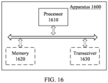
- FIG. 16 is a schematic structural diagram of an apparatus according to an embodiment of this application. Dashed lines in FIG. 16 indicate that a unit or module is optional.
- the apparatus 1600 may be used to implement the methods described in the foregoing method embodiments.
- the apparatus 1600 may be a chip or a communications apparatus.
- the apparatus 1600 may further include a transceiver 1630.
- the processor 1610 may communicate with another device or chip through the transceiver 1630.
- the processor 1610 may transmit data to and receive data from another device or chip through the transceiver 1630.
- An embodiment of this application further provides a computer-readable storage medium for storing a program.
- the computer-readable storage medium may be applied to a communications apparatus provided in embodiments of this application, and the program causes a computer to execute the methods to be executed by the communications apparatus in various embodiments of this application.
- An embodiment of this application further provides a computer program product.
- the computer program product includes a program.
- the computer program product may be applied to a communications apparatus provided in embodiments of this application, and the program causes a computer to execute the methods to be executed by the communications apparatus in various embodiments of this application.
- An embodiment of this application further provides a computer program.
- the computer program may be applied to a communications apparatus provided in embodiments of this application, and the computer program causes a computer to execute the methods to be executed by the communications apparatus in various embodiments of this application.
- B that is corresponding to A means that B is associated with A, and B may be determined based on A.
- determining B based on A does not mean determining B based only on A, but instead B may be determined based on A and/or other information.
- sequence numbers of the foregoing processes do not mean execution sequences.
- the execution sequences of the processes should be determined based on functions and internal logic of the processes, and should not be construed as any limitation on the implementation processes of embodiments of this application.
- the disclosed system, apparatus, and method may be implemented in other manners.
- the described apparatus embodiments are merely examples.
- the unit division is merely logical function division and may be other division in actual implementation.
- a plurality of units or components may be combined or integrated into another system, or some features may be ignored or not performed.
- the displayed or discussed mutual couplings or direct couplings or communication connections may be implemented through some interfaces.
- the indirect couplings or communication connections between the apparatus or units may be implemented in electronic, mechanical, or other forms.
- the units described as separate parts may or may not be physically separate, and parts displayed as units may or may not be physical units, and may be located in one place, or may be distributed on a plurality of network units. Some or all of the units may be selected according to actual needs to achieve the objective of the solutions of embodiments.
- All or some of the foregoing embodiments may be implemented by using software, hardware, firmware, or any combination thereof.
- the foregoing embodiments may be implemented completely or partially in a form of a computer program product.
- the computer program product includes one or more computer instructions.
- the computer may be a general-purpose computer, a dedicated computer, a computer network, or another programmable apparatus.
- the computer instructions may be stored in a computer-readable storage medium or transmitted from one computer-readable storage medium to another computer-readable storage medium.
- the computer instructions may be transmitted from a website, computer, server, or data center to another website, computer, server, or data center in a wired (for example, a coaxial cable, an optical fiber, and a digital subscriber line (digital subscriber line, DSL)) manner or a wireless (for example, infrared, wireless, and microwave) manner.
- the computer-readable storage medium may be any usable medium readable by the computer, or a data storage device, such as a server or a data center, integrating one or more usable media.
- the usable medium may be a magnetic medium (for example, a floppy disk, a hard disk, or a magnetic tape), an optical medium (for example, a digital video disc (digital video disc, DVD)), a semiconductor medium (for example, a solid state disk (solid state disk, SSD)), or the like.
- a magnetic medium for example, a floppy disk, a hard disk, or a magnetic tape
- an optical medium for example, a digital video disc (digital video disc, DVD)
- a semiconductor medium for example, a solid state disk (solid state disk, SSD)
Landscapes
- Engineering & Computer Science (AREA)
- Computer Networks & Wireless Communication (AREA)
- Signal Processing (AREA)
- Mobile Radio Communication Systems (AREA)
- Selective Calling Equipment (AREA)
Applications Claiming Priority (1)
| Application Number | Priority Date | Filing Date | Title |
|---|---|---|---|
| PCT/CN2022/089950 WO2023206254A1 (zh) | 2022-04-28 | 2022-04-28 | 通信方法及通信装置 |
Publications (2)
| Publication Number | Publication Date |
|---|---|
| EP4518441A1 true EP4518441A1 (de) | 2025-03-05 |
| EP4518441A4 EP4518441A4 (de) | 2026-03-04 |
Family
ID=88516786
Family Applications (1)
| Application Number | Title | Priority Date | Filing Date |
|---|---|---|---|
| EP22939106.5A Pending EP4518441A4 (de) | 2022-04-28 | 2022-04-28 | Kommunikationsverfahren und kommunikationsvorrichtung |
Country Status (4)
| Country | Link |
|---|---|
| US (1) | US20250071676A1 (de) |
| EP (1) | EP4518441A4 (de) |
| CN (1) | CN119072961A (de) |
| WO (1) | WO2023206254A1 (de) |
Families Citing this family (9)
| Publication number | Priority date | Publication date | Assignee | Title |
|---|---|---|---|---|
| US12395014B2 (en) * | 2019-11-20 | 2025-08-19 | Rutgers, The State University Of New Jersey | In-body wireless charging system |
| WO2025102342A1 (zh) * | 2023-11-17 | 2025-05-22 | Oppo广东移动通信有限公司 | 传输状态确定方法及装置、终端设备、网络设备 |
| WO2025137888A1 (zh) * | 2023-12-26 | 2025-07-03 | 北京小米移动软件有限公司 | 通信方法及装置、通信设备、通信系统、存储介质 |
| WO2025171671A1 (zh) * | 2024-02-18 | 2025-08-21 | Oppo广东移动通信有限公司 | 无线通信方法、通信设备、装置以及存储介质 |
| WO2025208300A1 (zh) * | 2024-04-01 | 2025-10-09 | 北京小米移动软件有限公司 | 通信方法及装置、通信设备、通信系统、存储介质 |
| WO2026011308A1 (zh) * | 2024-07-09 | 2026-01-15 | Oppo广东移动通信有限公司 | 无线通信的方法及通信设备 |
| US20260067812A1 (en) * | 2024-08-29 | 2026-03-05 | Huawei Technologies Co., Ltd. | Systems, apparatuses, methods, and non-transitory computer-readable storage devices for wireless communication employing energy-state reporting methods for ambient-power wireless local area network (wlan) devices |
| CN122002627A (zh) * | 2024-11-07 | 2026-05-08 | 荣耀终端股份有限公司 | 通信方法及装置 |
| CN119342451B (zh) * | 2024-12-04 | 2025-11-14 | 荣耀终端股份有限公司 | 数据传输方法及相关装置 |
Family Cites Families (4)
| Publication number | Priority date | Publication date | Assignee | Title |
|---|---|---|---|---|
| CN107408846B (zh) * | 2015-07-31 | 2020-04-14 | 华为技术有限公司 | 用于rf能量采集的无线通信设备和方法 |
| CN106604382B (zh) * | 2015-10-16 | 2020-11-27 | 华为技术有限公司 | 一种低功耗的通信方法及装置 |
| US20180255514A1 (en) * | 2017-03-06 | 2018-09-06 | Qualcomm Incorporated | Dynamic frequency selection channel friendly wake-up radio operations |
| CN108810877B (zh) * | 2017-05-05 | 2020-08-14 | 电信科学技术研究院 | 一种调整终端能力的方法、网络侧设备及终端 |
-
2022
- 2022-04-28 EP EP22939106.5A patent/EP4518441A4/de active Pending
- 2022-04-28 CN CN202280095240.7A patent/CN119072961A/zh active Pending
- 2022-04-28 WO PCT/CN2022/089950 patent/WO2023206254A1/zh not_active Ceased
-
2024
- 2024-10-25 US US18/926,418 patent/US20250071676A1/en active Pending
Also Published As
| Publication number | Publication date |
|---|---|
| WO2023206254A1 (zh) | 2023-11-02 |
| EP4518441A4 (de) | 2026-03-04 |
| CN119072961A (zh) | 2024-12-03 |
| US20250071676A1 (en) | 2025-02-27 |
Similar Documents
| Publication | Publication Date | Title |
|---|---|---|
| US20250071676A1 (en) | Communication method and communications apparatus | |
| US20250038842A1 (en) | Wireless communication method and wireless communications apparatus | |
| US20250039727A1 (en) | Communication method and communications apparatus | |
| WO2025160778A1 (zh) | 信道配置方法及装置、通信设备、通信系统、存储介质 | |
| US20250097921A1 (en) | Wireless communication methods, terminal devices, and network devices | |
| US20260122553A1 (en) | Communication method and communications apparatus | |
| US20250247837A1 (en) | Wireless communication method and device | |
| US20240147222A1 (en) | Terminal recognition method and computer device | |
| US20250212205A1 (en) | Communication method and communications apparatus | |
| US20250365662A1 (en) | Method for wireless communication, network device, and ambient power-enabled (amp) device | |
| US20250008497A1 (en) | Method for configuring resources, terminal, and network device | |
| US20240259939A1 (en) | Communication method, terminal, and network device | |
| US20250056416A1 (en) | Data transmission methods, first device and second device | |
| WO2024190562A1 (ja) | 通信制御方法 | |
| US20260032755A1 (en) | Wireless communication method and communication apparatus | |
| EP4676130A1 (de) | Verfahren zur drahtlosen kommunikation sowie endgerätevorrichtung und netzwerkvorrichtung | |
| US20260129562A1 (en) | Communication method and apparatus, communication device, chip, and computer storage medium | |
| US20260122593A1 (en) | Wireless communication methods, terminal devices and communication devices | |
| WO2024187419A1 (zh) | 无线通信方法、终端设备及网络设备 | |
| WO2025171663A1 (zh) | 无线通信的方法及通信设备 | |
| WO2026102777A1 (zh) | 无线通信方法、装置、设备及存储介质 | |
| WO2024098403A1 (zh) | 无线通信的方法及设备 | |
| WO2025171671A1 (zh) | 无线通信方法、通信设备、装置以及存储介质 | |
| WO2025171666A1 (zh) | 无线通信方法及通信设备 | |
| WO2026066690A1 (zh) | 一种数据传输方法及装置 |
Legal Events
| Date | Code | Title | Description |
|---|---|---|---|
| STAA | Information on the status of an ep patent application or granted ep patent |
Free format text: STATUS: THE INTERNATIONAL PUBLICATION HAS BEEN MADE |
|
| PUAI | Public reference made under article 153(3) epc to a published international application that has entered the european phase |
Free format text: ORIGINAL CODE: 0009012 |
|
| STAA | Information on the status of an ep patent application or granted ep patent |
Free format text: STATUS: REQUEST FOR EXAMINATION WAS MADE |
|
| 17P | Request for examination filed |
Effective date: 20241127 |
|
| AK | Designated contracting states |
Kind code of ref document: A1 Designated state(s): AL AT BE BG CH CY CZ DE DK EE ES FI FR GB GR HR HU IE IS IT LI LT LU LV MC MK MT NL NO PL PT RO RS SE SI SK SM TR |
|
| DAV | Request for validation of the european patent (deleted) | ||
| DAX | Request for extension of the european patent (deleted) | ||
| A4 | Supplementary search report drawn up and despatched |
Effective date: 20260204 |
|
| RIC1 | Information provided on ipc code assigned before grant |
Ipc: H04W 52/02 20090101AFI20260129BHEP Ipc: H04W 72/04 20230101ALI20260129BHEP Ipc: H04W 8/24 20090101ALI20260129BHEP |