EP4518452A1 - Verfahren zum senden und empfangen eines uplink-kanals und downlink-kanals sowie vorrichtung dafür - Google Patents
Verfahren zum senden und empfangen eines uplink-kanals und downlink-kanals sowie vorrichtung dafür Download PDFInfo
- Publication number
- EP4518452A1 EP4518452A1 EP23796732.8A EP23796732A EP4518452A1 EP 4518452 A1 EP4518452 A1 EP 4518452A1 EP 23796732 A EP23796732 A EP 23796732A EP 4518452 A1 EP4518452 A1 EP 4518452A1
- Authority
- EP
- European Patent Office
- Prior art keywords
- signal
- time duration
- duration
- information
- time
- Prior art date
- Legal status (The legal status is an assumption and is not a legal conclusion. Google has not performed a legal analysis and makes no representation as to the accuracy of the status listed.)
- Pending
Links
Images



Classifications
-
- H—ELECTRICITY
- H04—ELECTRIC COMMUNICATION TECHNIQUE
- H04L—TRANSMISSION OF DIGITAL INFORMATION, e.g. TELEGRAPHIC COMMUNICATION
- H04L5/00—Arrangements affording multiple use of the transmission path
- H04L5/003—Arrangements for allocating sub-channels of the transmission path
- H04L5/0044—Allocation of payload; Allocation of data channels, e.g. PDSCH or PUSCH
-
- H—ELECTRICITY
- H04—ELECTRIC COMMUNICATION TECHNIQUE
- H04L—TRANSMISSION OF DIGITAL INFORMATION, e.g. TELEGRAPHIC COMMUNICATION
- H04L5/00—Arrangements affording multiple use of the transmission path
- H04L5/003—Arrangements for allocating sub-channels of the transmission path
- H04L5/0053—Allocation of signalling, i.e. of overhead other than pilot signals
- H04L5/0057—Physical resource allocation for CQI
-
- H—ELECTRICITY
- H04—ELECTRIC COMMUNICATION TECHNIQUE
- H04B—TRANSMISSION
- H04B7/00—Radio transmission systems, i.e. using radiation field
- H04B7/02—Diversity systems; Multi-antenna system, i.e. transmission or reception using multiple antennas
- H04B7/04—Diversity systems; Multi-antenna system, i.e. transmission or reception using multiple antennas using two or more spaced independent antennas
- H04B7/06—Diversity systems; Multi-antenna system, i.e. transmission or reception using multiple antennas using two or more spaced independent antennas at the transmitting station
- H04B7/0613—Diversity systems; Multi-antenna system, i.e. transmission or reception using multiple antennas using two or more spaced independent antennas at the transmitting station using simultaneous transmission
- H04B7/0615—Diversity systems; Multi-antenna system, i.e. transmission or reception using multiple antennas using two or more spaced independent antennas at the transmitting station using simultaneous transmission of weighted versions of same signal
- H04B7/0619—Diversity systems; Multi-antenna system, i.e. transmission or reception using multiple antennas using two or more spaced independent antennas at the transmitting station using simultaneous transmission of weighted versions of same signal using feedback from receiving side
- H04B7/0621—Feedback content
- H04B7/0626—Channel coefficients, e.g. channel state information [CSI]
-
- H—ELECTRICITY
- H04—ELECTRIC COMMUNICATION TECHNIQUE
- H04L—TRANSMISSION OF DIGITAL INFORMATION, e.g. TELEGRAPHIC COMMUNICATION
- H04L5/00—Arrangements affording multiple use of the transmission path
- H04L5/003—Arrangements for allocating sub-channels of the transmission path
- H04L5/0048—Allocation of pilot signals, i.e. of signals known to the receiver
-
- H—ELECTRICITY
- H04—ELECTRIC COMMUNICATION TECHNIQUE
- H04W—WIRELESS COMMUNICATION NETWORKS
- H04W52/00—Power management, e.g. Transmission Power Control [TPC] or power classes
- H04W52/02—Power saving arrangements
- H04W52/0203—Power saving arrangements in the radio access network or backbone network of wireless communication networks
- H04W52/0206—Power saving arrangements in the radio access network or backbone network of wireless communication networks in access points, e.g. base stations
-
- H—ELECTRICITY
- H04—ELECTRIC COMMUNICATION TECHNIQUE
- H04W—WIRELESS COMMUNICATION NETWORKS
- H04W52/00—Power management, e.g. Transmission Power Control [TPC] or power classes
- H04W52/02—Power saving arrangements
- H04W52/0209—Power saving arrangements in terminal devices
- H04W52/0225—Power saving arrangements in terminal devices using monitoring of external events, e.g. the presence of a signal
- H04W52/0229—Power saving arrangements in terminal devices using monitoring of external events, e.g. the presence of a signal where the received signal is a wanted signal
- H04W52/0235—Power saving arrangements in terminal devices using monitoring of external events, e.g. the presence of a signal where the received signal is a wanted signal where the received signal is a power saving command
-
- H—ELECTRICITY
- H04—ELECTRIC COMMUNICATION TECHNIQUE
- H04W—WIRELESS COMMUNICATION NETWORKS
- H04W72/00—Local resource management
- H04W72/04—Wireless resource allocation
- H04W72/044—Wireless resource allocation based on the type of the allocated resource
- H04W72/0446—Resources in time domain, e.g. slots or frames
-
- H—ELECTRICITY
- H04—ELECTRIC COMMUNICATION TECHNIQUE
- H04W—WIRELESS COMMUNICATION NETWORKS
- H04W72/00—Local resource management
- H04W72/12—Wireless traffic scheduling
- H04W72/1263—Mapping of traffic onto schedule, e.g. scheduled allocation or multiplexing of flows
-
- H—ELECTRICITY
- H04—ELECTRIC COMMUNICATION TECHNIQUE
- H04W—WIRELESS COMMUNICATION NETWORKS
- H04W72/00—Local resource management
- H04W72/20—Control channels or signalling for resource management
- H04W72/23—Control channels or signalling for resource management in the downlink direction of a wireless link, i.e. towards a terminal
-
- H—ELECTRICITY
- H04—ELECTRIC COMMUNICATION TECHNIQUE
- H04W—WIRELESS COMMUNICATION NETWORKS
- H04W72/00—Local resource management
- H04W72/20—Control channels or signalling for resource management
- H04W72/23—Control channels or signalling for resource management in the downlink direction of a wireless link, i.e. towards a terminal
- H04W72/231—Control channels or signalling for resource management in the downlink direction of a wireless link, i.e. towards a terminal the control data signalling from the layers above the physical layer, e.g. RRC or MAC-CE signalling
-
- H—ELECTRICITY
- H04—ELECTRIC COMMUNICATION TECHNIQUE
- H04W—WIRELESS COMMUNICATION NETWORKS
- H04W72/00—Local resource management
- H04W72/20—Control channels or signalling for resource management
- H04W72/23—Control channels or signalling for resource management in the downlink direction of a wireless link, i.e. towards a terminal
- H04W72/232—Control channels or signalling for resource management in the downlink direction of a wireless link, i.e. towards a terminal the control data signalling from the physical layer, e.g. DCI signalling
-
- H—ELECTRICITY
- H04—ELECTRIC COMMUNICATION TECHNIQUE
- H04W—WIRELESS COMMUNICATION NETWORKS
- H04W76/00—Connection management
- H04W76/20—Manipulation of established connections
- H04W76/28—Discontinuous transmission [DTX]; Discontinuous reception [DRX]
-
- Y—GENERAL TAGGING OF NEW TECHNOLOGICAL DEVELOPMENTS; GENERAL TAGGING OF CROSS-SECTIONAL TECHNOLOGIES SPANNING OVER SEVERAL SECTIONS OF THE IPC; TECHNICAL SUBJECTS COVERED BY FORMER USPC CROSS-REFERENCE ART COLLECTIONS [XRACs] AND DIGESTS
- Y02—TECHNOLOGIES OR APPLICATIONS FOR MITIGATION OR ADAPTATION AGAINST CLIMATE CHANGE
- Y02D—CLIMATE CHANGE MITIGATION TECHNOLOGIES IN INFORMATION AND COMMUNICATION TECHNOLOGIES [ICT], I.E. INFORMATION AND COMMUNICATION TECHNOLOGIES AIMING AT THE REDUCTION OF THEIR OWN ENERGY USE
- Y02D30/00—Reducing energy consumption in communication networks
- Y02D30/70—Reducing energy consumption in communication networks in wireless communication networks
Definitions
- the disclosure relates to a method and apparatus for transmitting and receiving an uplink (UL) channel and a downlink (DL) channel, and more particularly, to a method and apparatus for notifying a user equipment (UE) whether each of one or more time durations is ON/OFF and transmitting and receiving a DL/UL channel based on whether each of the one or more time durations is ON/OFF, for network energy saving (NES).
- UL uplink
- DL downlink
- NES network energy saving
- a future-generation 5th generation (5G) system is required to provide an enhanced wireless broadband communication, compared to the legacy LTE system.
- 5G future-generation 5th generation
- communication scenarios are divided into enhanced mobile broadband (eMBB), ultra-reliability and low-latency communication (URLLC), massive machine-type communication (mMTC), and so on.
- eMBB enhanced mobile broadband
- URLLC ultra-reliability and low-latency communication
- mMTC massive machine-type communication
- eMBB is a future-generation mobile communication scenario characterized by high spectral efficiency, high user experienced data rate, and high peak data rate
- URLLC is a future-generation mobile communication scenario characterized by ultra-high reliability, ultra-low latency, and ultra-high availability (e.g., vehicle to everything (V2X), emergency service, and remote control)
- mMTC is a future-generation mobile communication scenario characterized by low cost, low energy, short packet, and massive connectivity (e.g., Internet of things (IoT)).
- IoT Internet of things
- An object of the disclosure is to provide a method of transmitting and receiving uplink and downlink channels and an apparatus therefor.
- a method of transmitting an uplink (UL) signal or receiving a downlink (DL) signal by a user equipment (UE) in a wireless communication system may include receiving information related to at least one unavailable first time duration, and transmitting the UL signal or receiving the DL signal during at least one second time duration other than the at least one first time duration.
- a transmission of the UL signal and a reception of the DL signal may not be performed during the at least one first time duration, and the information related to the at least one first time duration may be received through downlink control information (DCI) or a medium access control-control element (MAC-CE).
- DCI downlink control information
- MAC-CE medium access control-control element
- the at least one first time duration may be one of a plurality of unavailable first time durations, indicated by the information.
- the at least one first time duration may be at least one symbol indicated as unavailable by a slot format indicator (SFI).
- SFI slot format indicator
- the at least one second time duration may be at least one symbol that is after expiration of a timer corresponding to the at least one first time duration.
- the reception of the DL signal and the transmission of the UL signal may be performed during the at least one first time duration.
- SSB synchronization signal block
- CSI-RS channel state information-reference signal
- PRACH physical random access channel
- a periodicity of a search space (SS) set for the at least one first time duration may be greater than a periodicity of an SS set for the at least one second time duration.
- the information related to the at least one first time duration may be for indicating a pattern including the at least one first time duration and the at least one second time duration, and information about a duration during which the pattern is applied may also be received through the DCI or the MAC-CE.
- a UL transmission or a DL reception may be performed in a time resource after an ending time of the duration.
- a UE for transmitting a UL signal or receiving a DL signal in a wireless communication system may include at least one transceiver, at least one processor, and at least one memory operably connected to the at least one processor and storing instructions which when executed, cause the at least one processor to perform operations.
- the operations may include receiving information related to at least one unavailable first time duration through the at least one transceiver, and transmitting the UL signal or receiving the DL signal through the at least one transceiver during at least one second time duration other than the at least one first time duration.
- a transmission of the UL signal and a reception of the DL signal may not be performed during the at least one first time duration, and the information related to the at least one first time duration is received through DCI or a MAC-CE.
- the at least one first time duration may be one of a plurality of unavailable first time durations, indicated by the information.
- the at least one first time duration may be at least one symbol indicated as unavailable by an SFI.
- the at least one second time duration may be at least one symbol that is after expiration of a timer corresponding to the at least one first time duration.
- the reception of the DL signal and the transmission of the UL signal may be performed during the at least one first time duration.
- a periodicity of an SS set for the at least one first time duration may be greater than a periodicity of an SS set for the at least one second time duration.
- the information related to the at least one first time duration may be for indicating a pattern including the at least one first time duration and the at least one second time duration, and information about a duration during which the pattern is applied may also be received through the DCI or the MAC-CE.
- a UL transmission or a DL reception may be performed based on a pattern different from the pattern and a duration corresponding to the different pattern, after an ending time of the duration.
- a computer-readable storage medium may include at least one computer program causing at least one processor to perform operations.
- the operations may include receiving information related to at least one unavailable time duration, and transmitting the UL signal or receiving the DL signal during a time duration other than the at least one time duration.
- a transmission of the UL signal and a reception of the DL signal may not be performed during the at least one time duration, and the information related to the at least one time duration may be received through DCI or a MAC-CE.
- OFDMA may be implemented as a radio technology such as institute of electrical and electronics engineers (IEEE) 802.11 (wireless fidelity (Wi-Fi)), IEEE 802.16 (worldwide interoperability for microwave access (WiMAX)), IEEE 802.20, evolved UTRA (E-UTRA), and so on.
- IEEE institute of electrical and electronics engineers
- Wi-Fi wireless fidelity
- WiMAX worldwide interoperability for microwave access
- E-UTRA evolved UTRA
- UTRA is a part of universal mobile telecommunications system (UMTS).
- 3 rd generation partnership project (3GPP) long term evolution (LTE) is a part of evolved UMTS (E-UMTS) using E-UTRA
- LTE-advanced (LTE-A) is an evolution of 3GPP LTE.
- 3GPP new radio or new radio access technology (NR) is an evolved version of 3GPP LTE/LTE-A.
- KPI key performance indicator
- Cloud storage is one particular use case driving the growth of uplink data rates.
- 5G will also be used for remote work in the cloud which, when done with tactile interfaces, requires much lower end-to-end latencies in order to maintain a good user experience.
- Entertainment for example, cloud gaming and video streaming, is another key driver for the increasing need for mobile broadband capacity. Entertainment will be very essential on smart phones and tablets everywhere, including high mobility environments such as trains, cars and airplanes.
- Another use case is AR for entertainment and information search, which requires very low latencies and significant instant data volumes.
- the automotive sector is expected to be a very important new driver for 5G, with many use cases for mobile communications for vehicles. For example, entertainment for passengers requires simultaneous high capacity and high mobility mobile broadband, because future users will expect to continue their good quality connection independent of their location and speed.
- Other use cases for the automotive sector are AR dashboards. These display overlay information on top of what a driver is seeing through the front window, identifying objects in the dark and telling the driver about the distances and movements of the objects.
- wireless modules will enable communication between vehicles themselves, information exchange between vehicles and supporting infrastructure and between vehicles and other connected devices (e.g., those carried by pedestrians).
- Safety systems may guide drivers on alternative courses of action to allow them to drive more safely and lower the risks of accidents.
- the next stage will be remote-controlled or self-driving vehicles.
- a smart grid interconnects such sensors, using digital information and communications technology to gather and act on information. This information may include information about the behaviors of suppliers and consumers, allowing the smart grid to improve the efficiency, reliability, economics and sustainability of the production and distribution of fuels such as electricity in an automated fashion.
- a smart grid may be seen as another sensor network with low delays.
- the health sector has many applications that may benefit from mobile communications.
- Communications systems enable telemedicine, which provides clinical health care at a distance. It helps eliminate distance barriers and may improve access to medical services that would often not be consistently available in distant rural communities. It is also used to save lives in critical care and emergency situations.
- Wireless sensor networks based on mobile communication may provide remote monitoring and sensors for parameters such as heart rate and blood pressure.
- Wireless and mobile communications are becoming increasingly important for industrial applications. Wires are expensive to install and maintain, and the possibility of replacing cables with reconfigurable wireless links is a plausible opportunity for many industries. However, achieving this requires that the wireless connection works with a similar delay, reliability and capacity as cables and that its management is simplified. Low delays and very low error probabilities are new requirements that need to be addressed with 5G.
- logistics and freight tracking are important use cases for mobile communications that enable the tracking of inventory and packages wherever they are by using location-based information systems.
- the logistics and freight tracking use cases typically require lower data rates but need wide coverage and reliable location information.
- FIG. 1 illustrates physical channels and a general signal transmission method using the physical channels in a 3GPP system.
- the UE When a UE is powered on or enters a new cell, the UE performs initial cell search (S11).
- the initial cell search involves acquisition of synchronization to a BS.
- the UE receives a synchronization signal block (SSB) from the BS.
- the SSB includes a primary synchronization signal (PSS), a secondary synchronization signal (SSS), and a physical broadcast channel (PBCH).
- PSS primary synchronization signal
- SSS secondary synchronization signal
- PBCH physical broadcast channel
- the UE synchronizes its timing to the BS and acquires information such as a cell identifier (ID) based on the PSS/SSS. Further, the UE may acquire information broadcast in the cell by receiving the PBCH from the BS.
- the UE may also monitor a DL channel state by receiving a downlink reference signal (DL RS).
- DL RS downlink reference signal
- the UE may acquire more detailed system information by receiving a physical downlink control channel (PDCCH) and a physical downlink shared channel (PDSCH) corresponding to the PDCCH (S12).
- PDCCH physical downlink control channel
- PDSCH physical downlink shared channel
- the UE may perform a random access procedure with the BS (S13 to S16). Specifically, the UE may transmit a preamble on a physical random access channel (PRACH) (S13) and may receive a PDCCH and a random access response (RAR) for the preamble on a PDSCH corresponding to the PDCCH (S14). The UE may then transmit a physical uplink shared channel (PUSCH) by using scheduling information in the RAR (S15), and perform a contention resolution procedure including reception of a PDCCH and a PDSCH signal corresponding to the PDCCH (S16).
- PRACH physical random access channel
- RAR random access response
- steps S13 and S15 may be performed as one step (in which Message A is transmitted by the UE), and steps S14 and S16 may be performed as one step (in which Message B is transmitted by the BS).
- the UE may receive a PDCCH and/or a PDSCH from the BS (S17) and transmit a physical uplink shared channel (PUSCH) and/or a physical uplink control channel (PUCCH) to the BS (S18), in a general UL/DL signal transmission procedure.
- Control information that the UE transmits to the BS is generically called uplink control information (UCI).
- the UCI includes a hybrid automatic repeat and request acknowledgement/negative acknowledgement (HARQ-ACK/NACK), a scheduling request (SR), channel state information (CSI), and so on.
- the CSI includes a channel quality indicator (CQI), a precoding matrix index (PMI), a rank indication (RI), and so on.
- UCI is transmitted on a PUCCH.
- control information and data may be transmitted on a PUSCH.
- the UE may transmit the UCI aperiodically on the PUSCH, upon receipt of a request/command from a network.
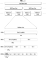
- FIG. 2 illustrates a radio frame structure
- Each radio frame has a length of 10 ms and is divided into two 5-ms half-frames. Each half-frame is divided into five 1-ms subframes. A subframe is divided into one or more slots, and the number of slots in a subframe depends on a subcarrier spacing (SCS).
- SCS subcarrier spacing
- Each slot includes 12 or 14 OFDM(A) symbols according to a cyclic prefix (CP). When a normal CP is used, each slot includes 14 OFDM symbols. When an extended CP is used, each slot includes 12 OFDM symbols.
- a symbol may include an OFDM symbol (or a CP-OFDM symbol) and an SC-FDMA symbol (or a discrete Fourier transform-spread-OFDM (DFT-s-OFDM) symbol).
- Table 1 exemplarily illustrates that the number of symbols per slot, the number of slots per frame, and the number of slots per subframe vary according to SCSs in a normal CP case.
- Table 2 illustrates that the number of symbols per slot, the number of slots per frame, and the number of slots per subframe vary according to SCSs in an extended CP case.
- the frame structure is merely an example, and the number of subframes, the number of slots, and the number of symbols in a frame may be changed in various manners.
- different OFDM(A) numerologies e.g., SCSs, CP lengths, and so on
- SCSs CP lengths
- CP lengths CP lengths, and so on
- the (absolute time) duration of a time resource e.g., a subframe, a slot, or a transmission time interval (TTI)
- TTI transmission time interval
- TU time unit
- various numerologies may be supported to support various 5 th generation (5G) services.
- 5G 5 th generation
- an SCS of 15 kHz a wide area in traditional cellular bands may be supported, while with an SCS of 30 kHz or 60 kHz, a dense urban area, a lower latency, and a wide carrier bandwidth may be supported.
- an SCS of 60 kHz or higher a bandwidth larger than 24.25 kHz may be supported to overcome phase noise.
- An NR frequency band may be defined by two types of frequency ranges, FR1 and FR2.
- FR1 and FR2 may be configured as described in Table 3 below.
- FR2 may be millimeter wave (mmW).
- mmW millimeter wave
- RNTI radio network temporary identifier
- the CRC is masked by a UE ID (e.g., cell-RNTI (C-RNTI)).
- C-RNTI cell-RNTI
- P-RNTI paging-RNTI
- SIB system information block
- SI-RNTI system information RNTI
- RA-RNTI random access-RNTI
- the PDCCH uses a fixed modulation scheme (e.g., QPSK).
- One PDCCH includes 1, 2, 4, 8, or 16 control channel elements (CCEs) according to its aggregation level (AL).
- One CCE includes 6 resource element groups (REGs), each REG being defined by one OFDM symbol by one (P)RB.
- the UE may monitor (e.g., blind-decode) a set of PDCCH candidates in the CORESET.
- the PDCCH candidates are CCE(s) that the UE monitors for PDCCH reception/detection.
- the PDCCH monitoring may be performed in one or more CORESETs in an active DL BWP on each active cell configured with PDCCH monitoring.
- a set of PDCCH candidates monitored by the UE is defined as a PDCCH search space (SS) set.
- the SS set may be a common search space (CSS) set or a UE-specific search space (USS) set.
- Table 4 lists exemplary PDCCH SSs.
- Type Search Space RNTI Use Case Type0-PDCCH Common SI-RNTI on a primary cell SIB Decoding Type0A-PDCCH Common SI-RNTI on a primary cell SIB Decoding Type1-PDCCH Common RA-RNTI or TC-RNTI on a primary cell Msg2, Msg4 decoding in RACH Type2-PDCCH Common P-RNTI on a primary cell Paging Decoding Type3-PDCCH Common INT-RNTI, SFI-RNTI, TPC-PUSCH-RNTI, TPC-PUCCH-RNTI, TPC-SRS-RNTI, C-RNTI, MCS-C-RNTI, or CS-RNTI(s) UE Specific UE Specific C-RNTI, or MCS-C-RNTI, or CS-RNTI(s) User specific PDSCH decoding
- the SS set may be configured by system information (e.g., MIB) or UE-specific higher-layer (e.g., RRC) signaling. S or fewer SS sets may be configured in each DL BWP of a serving cell. For example, the following parameters/information may be provided for each SS set.
- Each SS set may be associated with one CORESET, and each CORESET configuration may be associated with one or more SS sets.
- - searchSpaceId indicates the ID of the SS set.
- the UE may monitor PDCCH candidates in one or more SS sets in a slot based on a CORESET/SS set configuration.
- An occasion e.g., time/frequency resources
- PDCCH (monitoring) occasion is defined as a PDCCH (monitoring) occasion.
- PDCCH (monitoring) occasion may be configured in a slot.
- Table 5 illustrates exemplary DCI formats transmitted on the PDCCH.
- DCI format 0_0 may be used to schedule a TB-based (or TB-level) PUSCH
- DCI format 0_1 may be used to schedule a TB-based (or TB-level) PUSCH or a code block group (CBG)-based (or CBG-level) PUSCH
- DCI format 1_0 may be used to schedule a TB-based (or TB-level) PDSCH
- DCI format 1_1 may be used to schedule a TB-based (or TB-level) PDSCH or a CBG-based (or CBG-level) PDSCH (DL grant DCI).
- DCI format 0_0/0_1 may be referred to as UL grant DCI or UL scheduling information
- DCI format 1_0/1_1 may be referred to as DL grant DCI or DL scheduling information
- DCI format 2_0 is used to deliver dynamic slot format information (e.g., a dynamic slot format indicator (SFI)) to a UE
- DCI format 2_1 is used to deliver DL pre-emption information to a UE.
- DCI format 2_0 and/or DCI format 2_1 may be delivered to a corresponding group of UEs on a group common PDCCH which is a PDCCH directed to a group of UEs.
- DCI format 0_0 and DCI format 1_0 may be referred to as fallback DCI formats, whereas DCI format 0_1 and DCI format 1_1 may be referred to as non-fallback DCI formats.
- a DCI size/field configuration is maintained to be the same irrespective of a UE configuration.
- the DCI size/field configuration varies depending on a UE configuration in the non-fallback DCI formats.
- a UE transmits a related signal to the BS on a UL channel, which will be described later, and the BS receives the related signal from the UE through the UL channel to be described later.
- PUCCH Physical Uplink Control Channel
- the PUCCH carries UCI, HARQ-ACK and/or scheduling request (SR), and is divided into a short PUCCH and a long PUCCH according to the PUCCH transmission length.
- SR scheduling request
- the UCI includes the following information.
- Table 6 illustrates exemplary PUCCH formats.
- PUCCH formats may be divided into short PUCCHs (Formats 0 and 2) and long PUCCHs (Formats 1, 3, and 4) based on PUCCH transmission durations.
- PUCCH format 0 conveys UCI of up to 2 bits and is mapped in a sequence-based manner, for transmission. Specifically, the UE transmits specific UCI to the BS by transmitting one of a plurality of sequences on a PUCCH of PUCCH format 0. Only when the UE transmits a positive SR, the UE transmits the PUCCH of PUCCH format 0 in PUCCH resources for a corresponding SR configuration.
- PUCCH format 1 conveys UCI of up to 2 bits and modulation symbols of the UCI are spread with an orthogonal cover code (OCC) (which is configured differently whether frequency hopping is performed) in the time domain.
- OCC orthogonal cover code
- the DMRS is transmitted in a symbol in which a modulation symbol is not transmitted (i.e., transmitted in time division multiplexing (TDM)).
- PUCCH format 2 conveys UCI of more than 2 bits and modulation symbols of the DCI are transmitted in frequency division multiplexing (FDM) with the DMRS.
- the DMRS is located in symbols #1, #4, #7, and #10 of a given RB with a density of 1/3.
- a pseudo noise (PN) sequence is used for a DMRS sequence.
- frequency hopping may be activated.
- PUCCH format 3 does not support UE multiplexing in the same PRBs, and conveys UCI of more than 2 bits. In other words, PUCCH resources of PUCCH format 3 do not include an OCC. Modulation symbols are transmitted in TDM with the DMRS.
- PUCCH format 4 supports multiplexing of up to 4 UEs in the same PRBS, and conveys UCI of more than 2 bits.
- PUCCH resources of PUCCH format 3 include an OCC. Modulation symbols are transmitted in TDM with the DMRS.
- the PUSCH carries UL data (e.g., UL-shared channel transport block (UL-SCH TB)) and/or UL control information (UCI), and is transmitted based a Cyclic Prefix-Orthogonal Frequency Division Multiplexing (CP-OFDM) waveform or a Discrete Fourier Transform-spread-Orthogonal Frequency Division Multiplexing (DFT-s-OFDM) waveform.
- CP-OFDM Cyclic Prefix-Orthogonal Frequency Division Multiplexing
- DFT-s-OFDM Discrete Fourier Transform-spread-Orthogonal Frequency Division Multiplexing
- the UE transmits the PUSCH by applying transform precoding.
- the UE may transmit the PUSCH based on the CP-OFDM waveform.
- transform precoding is allowed (e.g., transform precoding is enabled)
- the UE may transmit the PUSCH based on the CP-OFDM waveform or the DFT-s-OFDM waveform.
- PUSCH transmission may be dynamically scheduled by the UL grant in the DCI or may be semi-statically scheduled based on higher layer (e.g., RRC) signaling (and/or Layer 1 (L1) signaling (e.g., PDCCH)) (configured grant).
- PUSCH transmission may be performed on a codebook basis or a non-codebook basis.
- the BS may dynamically allocate resources for DL transmission to the UE by PDCCH(s) (including DCI format 1_0 or DCI format 1_1). Further, the BS may indicate to a specific UE that some of resources pre-scheduled for the UE have been pre-empted for signal transmission to another UE, by PDCCH(s) (including DCI format 2_1). Further, the BS may configure a DL assignment periodicity by higher-layer signaling and signal activation/deactivation of a configured DL assignment by a PDCCH in a semi-persistent scheduling (SPS) scheme, to provide a DL assignment for an initial HARQ transmission to the UE.
- SPS semi-persistent scheduling
- the BS When a retransmission for the initial HARQ transmission is required, the BS explicitly schedules retransmission resources through a PDCCH.
- the UE When a DCI-based DL assignment collides with an SPS-based DL assignment, the UE may give priority to the DCI-based DL assignment.
- the BS may dynamically allocate resources for UL transmission to the UE by PDCCH(s) (including DCI format 0_0 or DCI format 0_1). Further, the BS may allocate UL resources for initial HARQ transmission to the UE based on a configured grant (CG) method (similarly to SPS).
- CG configured grant
- a configured grant does not involve a PDCCH for a PUSCH transmission.
- UL resources for retransmission are explicitly allocated by PDCCH(s).
- an operation of preconfiguring UL resources without a dynamic grant (DG) e.g., a UL grant through scheduling DCI
- CG Two types are defined for the CG.
- Dynamic slot format indication information (e.g., DCI format 2_0)
- a slot format indicates per-symbol usages in a given slot, indicating one of downlink (D), uplink (U), or flexible (F) for each symbol.
- Slot format-related information may be transmitted in one or more of the following signals:
- the static or semi-static SFI may be indicated by cell-specific RRC signaling (e.g., TDD-UL-DL-ConfigurationCommon ) or UE-specific RRC signaling (e.g., TDD-UL-DL-ConfigDedicated ) .
- the measurement-related signal may be indicated by UE-specific RRC signaling, and indicate a periodic/semi-persistent CSI-RS for CSI reporting, periodic CSI reporting, a periodic/semi-persistent SRS, or the like.
- the UE-specific data transmission-related signal may include UE-specific DCI that triggers a PDSCH, a PUSCH, or a PUCCH with A/N for a PDSCH, and DCI that triggers an aperiodic measurement-related signal such as an aperiodic CSI-RS, an aperiodic SRS, or the like.
- the slot format includes a format for zero, one, or two switching points.
- FIG. E1 illustrates various slot formats. Specifically, FIG. 14(a) illustrates a slot format for zero switching points, FIG. 14(b) illustrates a slot format for one switching point, and FIG. 14(c) illustrates a slot format for two switching points.
- the slot format for zero switching points includes 14 DL symbols, 14 flexible symbols, or 14 UL symbols.
- the slot format for one switching point is configured to start with zero or more DL symbols and end with zero or more UL symbols, with one or more flexible symbols and DL/UL symbols in between.
- the slot format for two switching points includes first seven symbols starting with zero or more DL symbols and including one or more UL symbols ending in a 7 th symbol, and second seven symbols starting with one or more DL symbols and ending with zero or more UL symbols.
- the first seven symbols and the second seven symbols may each include zero or more flexible symbols.
- Up to 256 slot formats may be defined, and their configurations are defined by a standard document such as TS 38.211.
- the UE is configured with a UE-specific SFI table based on the up to 256 slot formats by higher-layer signaling and receives a specific index value in the UE-specific SFI table through DCI format 2_0 (or a group-common PDCCH).
- the UE determines a slot format based on the following prioritization of signals carrying the above-described slot format-related information. More specifically, when the UE receives slot format-related information through a plurality of signals, the UE considers indication information in signals prioritized as follows, only for the purpose of determining the usage of a symbol indicated as a flexible symbol by a high-priority signal.
- Slot format information by cell-specific higher-layer signaling e.g., TDD-UL-DL-ConfigurationCommon
- slot format information by UE-specific higher-layer signaling e.g., TDD-UL-DL-ConfigDedicated
- slot format information through a group common PDCCH e.g., DCI format 2_0
- UE-specific data transmission scheduling information > measurement-related scheduling information.
- the UE when a specific symbol in a slot is indicated as DL/UL to the UE by cell-specific RRC signaling or UE-specific RRC signaling, the UE does not expect DCI format 2_0 (or a group-specific PDCCH including DCI format 2_0) to indicate the specific symbol as UL/DL or flexible.
- the DCI format 2_0 (or the group-specific PDCCH including DCI format 2_0) indicates the specific symbol in the slot as a flexible symbol
- the UE transmits or receives a related signal in the specific symbol only when receiving separate scheduling information (e.g., UE-specific scheduling DCI), and otherwise, does not perform the signal transmission/reception in the specific symbol.
- the DCI format 2_0 may further include information about available RB set(s), a channel occupancy time (COT) duration, and switching of a search space set group.
- the DCI format 2_0 may include one or more of the following pieces of information.
- the CRC of the DCI format 2_0 may be scrambled with a UE group-common ID (e.g., SFI-RNTI).
- the size of the DCI format 2_0 may be configurable to be up to 128 bits by a higher layer (e.g., the RRC layer).
- An RB set corresponds to frequency resources in which a channel access process (CAP) is performed individually in a shared spectrum, and includes a plurality of contiguous (P)RBs.
- An available RB set indicator indicates the index of an RB set in which DL reception is available within a cell.
- a COT duration indicator indicates a COT shared between the BS and the UE in the shared spectrum.
- a monitoring group flag indicates a search space group to be monitored by the UE among a plurality of search space groups (e.g., group #0/#1) configured for the same cell.
- DCI format 2_0 is group-common control information, and the position (e.g., start point) of information for each UE may be indicated by higher-layer (e.g., RRC) signaling.
- availableRB-SetPerCell is a UE-specific signal, and may include information about the position (e.g., start point) of an available RB set indicator for the UE in the DCI format 2_0.
- CO-DurationPerCell and searchSpaceSwitchTrigger are also UE-specific signals and may each include information about the position (e.g., start point) of information for the UE in the DCI format 2_0.
- Energy saving of BSs is considered important in wireless communication systems including 3GPP, because it may contribute to building eco-friendly networks by reducing carbon emissions and reducing the operational expenditure (OPEX) of communication industry players.
- OPEX operational expenditure
- BSs should be equipped with more antennas and provide services in wider bandwidths and frequency bands.
- the energy cost of BSs has reached 20% of the total OPEX according to a recent study. Due to this increased interest in BS energy saving, a new study item called "study on network energy savings" was approved in 3GPP NR release 18.
- the following enhancement techniques are under consideration in order to improve the energy saving capability of BSs from the perspective of transmission and reception.
- the disclosure proposes a time-domain BS energy saving method.
- a scenario is mainly considered in which a BS dynamically configures/indicates a specific ON duration during which a DL or UL signal/channel is allowed to be transmitted and an OFF duration during which a DL or UL signal/channel is not allowed to be transmitted, thereby increasing a network energy saving (NES) gain.
- the BS may preconfigure a plurality of OFF durations to turn off transmission of a specific DL signal during a specific duration (e.g., one or more slot/symbol/subframe durations), and dynamically indicates one of the plurality of OFF durations to notify a UE that the DL signal will not be transmitted during a time period corresponding to the preconfigured OFF duration. Accordingly, the power consumption of the BS and the UE may be reduced, and an interference mitigation effect may be expected as well.
- a specific duration e.g., one or more slot/symbol/subframe durations
- an OFF duration may refer to a discontinuous transmission (DTX) period of the BS.
- the BS when it is said that the BS operates in the NES mode, this may mean that an operation such as bandwidth part (BWP) switching or dynamic resource block (RB) adaptation is performed in the frequency domain as well as in the time domain.
- BWP bandwidth part
- RB dynamic resource block
- the NES mode of the BS may refer to an operation mode in which, for example, when a specific transmission (Tx)/reception (Rx) antenna port of the BS is turned off semi-statically or dynamically in the spatial domain, the BS does not transmit and/or receive through the antenna port, thereby reducing the power consumption of the BS and the UE.
- FIGS. 6 to 8 are diagrams illustrating an overall operation process of a UE and a BS according to an embodiment of the disclosure.
- FIG. 6 is a diagram illustrating an overall operation process of a UE according to the disclosure.
- the UE may receive information related to an NES operation of a BS (S601).
- the information related to the NES operation may be information related to ON/OFF of one or more time durations or information related to whether the BS operates in an NES mode.
- it may be information related to a periodicity of a DL/UL signal/channel according to the NES mode.
- the UE may receive the information related to the NES operation based on at least one of [Method #1] to [Method #7].
- the UE may receive/transmit a DL/UL channel during one or more time durations based on the information related to the NES operation (S603). For example, the UE may receive/transmit the DL/UL channel based on at least one of [Method #1] to [Method #7].
- FIG. 7 is a diagram illustrating an overall operation process of a BS according to the disclosure.
- the BS may transmit information related to an NES operation of the BS (S701).
- the information related to the NES operation may be information related to ON/OFF of one or more time durations, or information related to whether the BS operates in an NES mode.
- it may be information related to a periodicity of a DL/UL signal/channel according to the NES mode.
- the BS may transmit the information related to the NES operation based on at least one of [Method #1] to [Method #7].
- the BS may transmit/receive a DL/UL channel during one or more time durations based on the information related to the NES operation (S603). For example, the BS may transmit/receive the DL/UL channel based on at least one of [Method #1] to [Method #7].
- FIG. 8 is a diagram illustrating an overall operation process of a network according to the disclosure.
- a BS may transmit information related to an NES operation of the BS to a UE (S801).
- the information related to the NES operation may be information related to ON/OFF of one or more time durations, or information related to whether the BS operates in an NES mode. Alternatively, it may be information related to a periodicity of a DL/UL signal/channel according to the NES mode.
- the BS may transmit the information related to the NES operation to the UE based on at least one of [Method #1] to [Method #7].
- the BS may transmit/receive a DL/UL channel during one or more time durations to/from the UE based on the information related to the NES operation (S803). For example, the BS may transmit/receive the DL/UL channel to/from the UE based on at least one of [Method #1] to [Method #7].
- a specific time duration may refer to one or more slots/symbols/subframes.
- Method #1 Method of indicating OFF of a DL/UL signal/channel during a specific time duration by (group-common) downlink control information (DCI) or a medium access control-control element (MAC-CE) by a BS
- DCI downlink control information
- MAC-CE medium access control-control element
- a timer value may be preconfigured, and when OFF is indicated, DL/UL signal/channel transmission/reception may be OFF during a corresponding timer duration. Further, when a corresponding timer expires, the DL/UL signal/channel transmission/reception may be ON again.
- an additional state e.g., N
- a symbol duration for which the state (e.g., N) is indicated by the SFI may be subject to an operation for an OFF duration, proposed by the proposed methods (e.g., an operation based on any one of Method #1 to Method #7).
- a specific DL/UL signal/channel may be allowed to be transmitted/received exceptionally even during a duration in which transmission/reception of a DL/UL signal/channel is OFF according to a proposed indication method of the disclosure.
- the specific DL/UL signal/channel may be synchronization signal block (SSB) and/or channel state information-reference signal (CSI-RS) for tracking and/or physical random access channel (PRACH).
- SSB synchronization signal block
- CSI-RS channel state information-reference signal
- PRACH physical random access channel
- a search space set group (SSSG) linked to an ON duration and an SSSG linked to an OFF duration may be configured separately, or the periodicity of SS sets during the OFF duration may be configured to be greater than the periodicity of SS sets during the ON duration.
- the preconfigured OFF duration and/or timer candidate values may be common to all DL/UL signals/channels.
- OFF duration and/or timer candidate values may be configured separately for each DL/UL signal/channel.
- the DL/UL signal/channel to be turned off may be preconfigured or predefined or directly indicated by the BS.
- the associated signal/channel may also be turned off.
- the signal/channel to be turned OFF may also include a PDCCH, and when the PDCCH is turned off, the UE may not perform PDCCH monitoring during an OFF duration and/or timer duration.
- the UE may perform PDCCH monitoring during the OFF duration and/or timer duration, and receive an indication to lengthen the OFF duration or an indication to switch to an ON duration through the PDCCH.
- the starting time and length of applying the OFF duration and/or timer may be configured by a separate parameter when OFF durations and/or timer candidate values are configured, or may be configured by joint encoding with each of OFF duration and/or timer candidate values.
- the starting time and length of applying the OFF duration and/or timer may be determined as a pre-agreed value (e.g., a specific value defined in the standard), or may be configured differently for each UE in consideration of a processing time of the UE.
- the starting time and length of applying the OFF duration and/or timer may be dynamically indicated together with an OFF indication by (group-common) DCI or a MAC-CE.
- inactivity-related timers e.g., BWPinactiveTimer, SCellinactiveTimer, dataInactivityTimer, and discontinuous reception (DRX)-related timer
- DRX discontinuous reception
- the methods may be inefficient and difficult to use in delay-sensitive services such as ultra reliable low latency communication (URLLC). Therefore, there may be a need for a method of dynamically configuring/indicating an ON/OFF duration for a DL/UL signal/channel, in units of symbols which are finer in granularity than subframes/slots, to reduce the power consumption of a BS and a UE, while minimizing a decrease in the data transmission/reception rate of the UE.
- URLLC ultra reliable low latency communication
- a plurality of ON/OFF durations configurable in units of symbols may be preconfigured for each UL/DL signal/channel by higher layer signaling such as radio resource control (RRC) signaling, and OFF of a specific DL/UL signal during a specific time duration may be indicated by (group-common) DCI or a MAC-CE.
- RRC radio resource control
- an ON/OFF duration configuration may be configured as ⁇ ON duration, duration 1, duration 2, ... , infinite value ⁇ .
- ON/OFF duration candidate values for a PDSCH may be configured as ⁇ ON, 2 symbols, 4 symbols, ... , infinite ⁇ , and one of the ON/OFF duration candidate values may be indicated.
- the indication is configured to be applied after 4 symbols, and 14 symbols is indicated by a MAC-CE, the PDSCH may be turned off during 14 symbols after 4 symbols from a time when the UE receives the indication, so that the BS does not transmit the PDSCH and the UE does not receive the PDSCH, thereby reducing power consumption.
- an infinite or inapplicable value may be configured as a preconfigured OFF duration candidate value, and when the infinite/non-numerical/inapplicable value is indicated by (GC-)DCI or a MAC CE, the UE may maintain a corresponding DL/UL signal/channel in the OFF state until an ON indication is received separately from the BS.
- a plurality of candidate timer values and a DL/UL signal/channel for which a corresponding timer is applied may be preconfigured.
- the DL/UL signal/channel for which the corresponding timer is applied may be configured commonly for the plurality of candidate timer values or may be configured separately for each of the plurality of candidate timer values.
- a specific DL/UL signal/channel may be turned off (deactivated) not to be transmitted or received for the corresponding timer value, so that the BS and the UE may obtain an energy saving effect.
- the specific DL/UL signal channel may be turned on (activated) again to be transmitted or received.
- the periodic CSI-RS may be tuned off (deactivated) within a time duration during which the timer is running, and turned on again to be transmitted/received after the specific time (e.g., 1 slot) from the expiration of the timer.
- the periodic CSI-RS may be transmitted and received after the ON duration in consideration of an original transmission timing of the periodic CSI-RS in the OFF duration.
- the periodic CSI-RS may be considered as dropped or deactivated during the OFF duration.
- the periodic CSI-RS may be transmitted and received as if it were a new periodic CSI-RS, on the assumption that the transmission and reception of the periodic CSI-RS is released during the OFF duration.
- the timer may also be started after the specific time (e.g., 1 slot) from the time when the DCI or MAC-CE is received, thereby entering the OFF duration.
- the preconfigured OFF duration and/or timer candidate values described above may be common to all DL/UL signals and channels or may be configured for each DL/UL signal and channel.
- specific OFF duration and/or timer candidate values may be configured for a single DL/UL signal/channel, or a plurality of DL or UL signals/channels may be used in conjunction with the same OFF duration and/or timer candidate values.
- a specific DL/UL signal/channel to be turned off by indicating an OFF duration and/or timer value may be preconfigured/pre-agreed or defined in the standard, or may be directly indicated by (group-common) DCI or a MAC-CE. Further, association between DL/UL signals/channels may be preconfigured, and when OFF of a specific signal/channel is indicated, the associated signal/channel may also be turned off.
- P-CSI-RS periodic CSI-RS
- P-SRS periodic SRS
- the signal/channel to be turned off may also include a PDCCH, and when the PDCCH is turned off, the UE may not perform PDCCH monitoring during an OFF duration and/or timer duration. When the PDCCH is not included in the OFF signal/channel, the UE may perform PDCCH monitoring during the OFF duration and/or timer duration, and receive an indication to lengthen the OFF duration or an indication to switch to an ON duration through the PDCCH.
- the starting time and length of applying the OFF duration and/or timer may be configured by a separate parameter when OFF duration and/or timer candidate values are configured, or may be configured by joint encoding with each of OFF duration and/or timer candidate values.
- the starting time and length of applying the OFF duration and/or timer may be determined as a pre-agreed value (e.g., a specific value defined in the standard), or may be configured differently for each UE in consideration of a processing time of the UE.
- the starting time and length of applying the OFF duration and/or timer may be dynamically indicated together with an OFF indication by (group-common) DCI or a MAC-CE.
- symbols in a slot may be semi-statically configured as U/D/F by cell-specific signaling or UE-specific signaling.
- a symbol configured as F for a UE configured with DCI format 2_0 monitoring may be dynamically indicated as one of D/U/F by DCI format 2_0.
- a UE not configured with SFI monitoring may perform RRC-configured DL/UL reception/transmission in a symbol configured as F.
- an SSSG linked to an ON duration and an SSSG linked to an OFF duration may be configured separately.
- SS set configuration#1 with a relatively small PDCCH monitoring periodicity may be used during an ON duration and switched to SS set configuration#2 with a relatively large PDCCH monitoring periodicity during an OFF duration.
- the above method is applicable to all DL/UL signals/channels (e.g., semi-persistent PDSCH and CG-PUSCH) which are preconfigured and transmitted, as well as the (periodic) CSI-RS, and a plurality of periodicity candidate values may be common to all DL/UL signals/channels or configured for each DL/UL signal/channel. Further, when the periodicity of a specific DL/UL signal/channel is indicated to be changed, the DL/UL signal/channel with the periodicity to be changed may be preconfigured or predefined or may be directly indicated.
- inactivity-related timers configured for the UE may be held during a duration in which a CSI-RS/SRS is not transmitted according to the changed periodicity and resumed when the duration ends, or may be stopped during the duration and restarted when the duration ends.
- the periodicity of a DL/UL signal/channel configured with the short periodicity is to be changed to the long periodicity or the very long periodicity in order to save power by maintaining the sleep mode as long as possible.
- (periodic) CSI-RS/SRSs may be pre-grouped into a plurality of groups according to their periodicities, and the BS may adjust a periodicity by indicating a specific one of the plurality of groups by (group-common) DCI or a MAC CE.
- group-common common one of the plurality of groups by (group-common) DCI or a MAC CE.
- CSI-RSs/SRSs with a short periodicity may be configured as group index #0
- CSI-RSs/SRSs with a long periodicity may be configured as group index #1.
- the BS may dynamically change the periodicity of a (periodic) CSI-RS/SRS by indicating one of group indexes #0 and #1 as needed.
- An SSB-based RRM measurement timing configuration is a period configured with measurement resources for radio resource management (RRM), similar to a discovery measurement timing configuration (DMTC) in the Long Term Evolution (LTE) system.
- RRM radio resource management
- the DRS is a signal defined for small cell enhancement in Release-12.
- the DRS is a control signal including a PSS/SSS/CRS and is transmitted periodically every 40ms.
- the SMTC is also a time window in which measurement resources for RRM may be configured in NR. Since there is no reference signal that is always transmitted like the CRS of LTE in NR, RRM may be performed in the SSS and PBCH-demodulation reference signal (DMRS) of an SS/PBCH block, and a CSI-RS configured in an active BWP.
- An SMTC-related configuration may include an SMTC window duration, periodicity, and timing offset, and a plurality of periodicities may be set for SMTC1 and SMTC2. For example, a plurality of SMTCs may be configured, and a periodicity may be set for each of the plurality of SMTCs. In this case, SMTC1 and SMTC2 may have different periodicities but the same timing offset and SMTC window duration.
- SSB and/or SIB e.g., PDSCH and PDCCH scheduling SIB
- paging e.g., DCI and paging message
- a plurality of periodicity candidate values may be preconfigured for the SSB/broadcast data/SMTC, and the BS may change the periodicity of the SSB/broadcast data/SMTC by indicating one of the plurality of periodicity candidate values by (GC-)DCI or a MAC CE.
- the SSB/SIB is an essential signal for initial access or radio resource measurement (RRM) of a UE, thus requiring periodic transmission.
- RRM radio resource measurement
- the SSB/SIB may be required to be transmitted periodically even in a situation where there is little data to transmit. In this case, it may be necessary to configure a plurality of periodicity candidate values and allow the BS to change the periodicity more dynamically by (group-common) DCI or a MAC-CE in order to reduce the power consumption of the BS.
- the above dynamic periodicity change method may be applicable not only to the (periodic) CSI-RS or SRS but also to all DL/UL signals/channels that are preconfigured and transmitted. Further, a plurality of periodicity candidate values may be common to all DL/UL signals/channels, or may be configured for each DL/UL signal/channel. Further, when the periodicity of a specific DL/UL signal/channel is indicated to be changed, the DL/UL signal/channel with the periodicity to be changed may be preconfigured or predefined, or may be directly indicated.
- association may be configured between DL/UL signals and channels, and when the periodicity of a specific signal/channel is indicated to be changed, the periodicity of the associated signal/channel may also be changed.
- An infinite or inapplicable value may be configured as a preconfigured periodicity candidate value, and when the infinite/non-numerical/inapplicable value is indicated by (GC-)DCI or a MAC CE, the existing periodicity may be maintained until an indication is given separately.
- a plurality of periodicity candidate values may be preconfigured for a semi-persistent (SPS)-PDSCH or a configured grant (CG)-PUSCH, and the BS may indicate one of the a plurality of periodicity candidate values by (group-common) DCI or a MAC CE.
- SPS-PDSCHs or CG-PUSCHs may be pre-grouped into a plurality of groups according to their periodicities, and the BS may adjust a periodicity by indicating a specific one of the plurality of groups by (group-common) DCI or a MAC CE.
- the periodicity of a periodic DL/UL signal/channel may be dynamically changed to a relatively large periodicity, thereby maximizing a duration (e.g., the duration of the sleep mode of the BS) in which transmission and reception of the DL/UL signal/channel is not allowed, and preventing unnecessary measurements and reporting of the UE. Accordingly, the overall power consumption of the UE and the BS may be reduced.
- Method #3 Method of preconfiguring a plurality of ON/OFF patterns and indicating a specific ON/OFF pattern by (group common) DCI or a MAC-CE
- Information related to a duration or timer during which an ON/OFF pattern lasts may be additionally configured in ON/OFF pattern configuration information, or the duration or timer during which the ON/OFF pattern lasts may be configured/indicated separately from the ON/OFF pattern configuration information.
- a duration or timer during which an ON/OFF pattern lasts ends, it may be switched to an ON duration or switched to a preconfigured next ON/OFF pattern and a duration or timer corresponding to the next ON/OFF pattern.
- Inactivity-related timers configured for the UE may be held during the OFF duration and resumed when the OFF duration ends, or may be stopped during the OFF duration and restarted when the OFF duration ends.
- a method may be considered in which similar to the DRX cycle of the UE, the BS also preconfigures an ON/OFF duration semi-statically, transmits/receives a DL/UL signal/channel normally during the ON duration, and switches its operation mode to the sleep mode/power saving mode during the OFF duration to reduce power consumption.
- this method of performing transmission and reception in a semi-static ON/OFF duration may obtain the energy saving effect during the preconfigured OFF duration.
- urgent traffic such as an SR or PRACH transmission of a UE
- the BS is not able to respond immediately until the ON duration, and the resulting large delay in transmitting an RAR or UL grant may degrade the performance of the UE.
- a plurality of ON/OFF patterns may be preconfigured, and the BS may dynamically change the lengths of the ON duration and the OFF duration by indicating a specific one of the plurality of ON/OFF patterns by (group-common) DCI or a MAC-CE.
- the BS may preconfigure ⁇ Pattern 1: Always ON, Pattern 2: 1 slot ON + 9 slots OFF, Pattern 3: 2 slots ON + 8 slots off, ... ⁇ for the UE, and dynamically indicate to the UE which one of the three patterns to be used to turn a DL/UL signal/channel on/off by (group-common) DCI or a MAC-CE.
- the DL/UL signal/channel for which the ON/OFF pattern and the duration of the ON/OFF pattern are to be applied may be preconfigured or defined (in the standard).
- the BS may directly indicate the DL/UL signal/channel for which the ON/OFF pattern and the duration of the ON/OFF pattern are to be applied.
- association is preconfigured between DL/UL signals/channels and an ON/OFF pattern and the duration of the ON/OFF pattern is indicated to be applied for a specific signal/channel
- the same ON/OFF pattern and duration of the ON/OFF pattern or a predefined specific ON/OFF pattern and the duration of the ON/OFF pattern may also be applied for the associated signal/channel.
- the P-SRS may also be transmitted and received according to the ON/OFF pattern and duration, or according to a specific ON/OFF pattern predefined for the P-SRS and the duration of the ON/OFF pattern.
- the BS since the BS configures ON/OFF for a plurality of time durations by one signaling in the form of a pattern, the power consumption of the UE and the BS may be reduced while reducing the signaling overhead of indicating ON/OFF for the plurality of durations. Further, an ON/OFF pattern is dynamically changed according to an operating state of a cell, while reducing signaling overhead, thereby minimizing the scheduling delay of the UE and DL/UL performance degradation and thus enabling efficient energy saving.
- Method #4 Operation of an advanced UE when a BS operates in a power saving mode.
- the power saving mode may mean that a DL/UL signal/channel is transmitted and received based on an OFF duration/timer/pattern according to Method #1, Method #2, and/or Method #3 of the disclosure.
- a penalty for PRACH transmission failure may not be applied.
- the penalty may mean applying power ramping, a preamble counter, and/or a preamble backoff.
- PRACH transmission failure may mean that the UE does not receive an RAR from the BS.
- RACH occasions (ROs) allocated to a duration in which an RAR window and an OFF duration overlap may be processed as invalid.
- a penalty for SR transmission failure may not be applied.
- the penalty may mean applying an SR counter and/or an SR prohibit timer.
- SR transmission failure may mean that the UE does not receive a response (e.g., UL grant) to an SR transmission of the UE from the BS.
- An SSB periodicity and an RO in the power saving mode are linked so that SSB-to-RO mapping may be implicitly changed according to a change of the SSB periodicity.
- SRS/CSI report/CG-PUSCH resources that overlap or are correlated with an OFF duration may be turned off.
- a more relaxed RAN4 requirement may be applied in a normal mode.
- POs preconfigured paging occasions
- the standard defines that the UE performs a subsequent operation such as ramping the transmission power of the PRACH, retransmitting it, increasing the counter value, backing off when a specific power value (e.g., maximum power) or maximum counter value is reached, selecting another PRACH preamble, and attempting retransmission.
- a specific power value e.g., maximum power
- the BS when the BS operates in the power saving mode, it may be configured that PRACH reception itself is not allowed during an OFF duration. Therefore, when the UE transmits the PRACH during the duration, the channel itself may be turned off and the BS may make no reception attempt, rather than the BS fails to properly receive the PRACH transmitted by the UE and fails to transmit the RAR. In this case, a different criterion from the previously defined subsequent UE operation may be required.
- a subsequent UE operation such as the above Method #4 may be defined for an advanced UE capable of receiving and applying a configuration/indication related to the power saving mode of a BS as in Method #1, Method #2, and Method #3 of the disclosure.
- a legacy UE since a legacy UE may not have the capability to apply the configuration/indication related to the power saving mode of the BS, it may inevitably follow the existing procedure defined in the standard for power saving of the BS, which may result in a penalty.
- a penalty for PRACH transmission failure may not be applied within the OFF duration/timer/pattern.
- the penalty may mean applying power ramping, a preamble counter, and/or a preamble backoff as described above.
- PRACH transmission failure may mean that the UE does not receive an RAR or a contention resolution message.
- the UE may not follow the existing subsequent procedures defined for RAR reception failure, considering that the BS intentionally does not receive it due to the OFF duration/timer/pattern preconfigured/indicated by the BS. For example, the UE may not perform power ramping for the PRACH, not apply the preamble counter and backoff, wait until an ON duration, and then transmit the PRACH again. In other words, during the ON duration, the UE may retransmit the PRACH with the same power as the PRACH transmitted during the OFF duration without increasing or decreasing the preamble counter and backoff.
- the UE transmits the PRACH in a specific RO
- an RAR window linked to the RO is configured, and only when the UE receives an RAR in response to the PRACH within the corresponding duration, the Msg1 transmission is considered successful.
- the RAR window linked to the specific RO overlaps with the OFF duration/timer/pattern of the BS, the BS may not perform transmission itself during the corresponding duration, and therefore, RAR transmission may not be expected. Therefore, to prevent an unnecessary PRACH transmission in an RO allocated to a duration in which the RAR window and the OFF duration overlap, the RO may be processed as invalid.
- the UE When there is UL data to be transmitted in a buffer, the UE transmits a PUCCH using an SR resource preconfigured by the BS.
- the BS When the BS successfully receives the SR PUCCH transmitted by the UE, it may allocate resources for a UL transmission of the UE by transmitting a UL grant.
- a penalty for SR transmission failure defined in the standard similar to a penalty for PRACH transmission failure may be applied.
- the penalty may mean applying an SR counter and/or an SR prohibit timer.
- SR transmission failure may mean that the UE does not receive a response (e.g., UL grant) to an SR transmission of the UE from the BS.
- the UL grant transmission is also turned off within an OFF duration/timer/pattern configured by the BS for power saving, for the same reason as failure of an RAR for a PRACH, and thus the SR is not intentionally received, a penalty such as an SR counter or SR prohibit timer may not be applied for the SR transmission, when the BS operates in the power saving mode.
- an SSB transmission may also be included within the OFF duration/timer/pattern for the power saving mode operation. Since there is a mapping relationship between an SSB and an RO, when an SSB periodicity is changed or the number of transmitted SSBs is reduced, the SSB-to-RO mapping also needs to be changed accordingly.
- the SSB-to-RO mapping relationship to be changed may be indicated explicitly, or implicitly according to a pre-agreement (e.g., defined in the standard) or a preconfiguration of the BS rather than indicated every time an event occurs.
- the SSB may be mapped to an RO every N radio frames or every multiple of N radio frames, or only in a few radio frames near the SSB (e.g., after the SSB is transmitted), rather than an RO is mapped to the SSB in each radio frame.
- the advanced UE may turn off the resources and reporting and not transmit them even without a separate indication/configuration from the BS.
- more relaxed RAN4 requirements than in the normal mode may be applied. For example, a cell selection/reselection criterion, RRM-related requirements, and/or time and frequency tracking/offset may be more relaxed than in the normal mode.
- power saving may be achieved by treating some of preconfigured paging occasions (POs) as invalid, for NES.
- POs preconfigured paging occasions
- this method may be a little detrimental to a legacy UE, the advanced UE may recognize invalid POs, and the BS may achieve the power saving effect by not performing transmission in some POs processed as invalid.
- the BS may notify the UE whether an associated serving cell (or BS) is currently operating in the power saving mode, or that the cell may operate in the power saving mode (even if it is not currently operating in the power saving mode), by using a pre-agreed SSB pattern/SIB/PBCH/paging DCI .
- An initial access UE or an idle/inactive UE may need to know that a BS that the UE is trying to access or camped on is operating in the power saving mode or is currently operating in the normal mode but may switch to the power saving mode.
- the legacy UE may perform the existing defined penalty procedure as in the example of Method #4 and thus unnecessarily continue retransmitting the PRACH or the SR, thereby unnecessarily consuming power.
- a procedure such as BWP switching or cell reselection may be triggered unnecessarily.
- the BS needs to notify the initial access or idle/inactive mode UE that the BS is operating in the power saving mode or the cell may operate in the power saving mode through a pre-agreed SSB pattern/SIB/PBCH/paging DCI.
- a specific multiplexing pattern between an SSB and a Type0-PDCCH or a specific FR1/FR2 subcarrier spacing (SCS) combination may be indicated.
- whether the BS is operating in the power saving mode and the possibility of operation in the power saving mode may be configured by information in SIB1 or a PBCH or paging DCI.
- the interpretation of a cell barring indication or the cell barring indication itself in SIB1 may be differentiated for the legacy UE and the advanced UE, and when a configuration indicating that the BS is operating in the power saving mode or may operate in the saving mode, the legacy UE may camp on another cell without camping on the BS by performing a cell barring operation, whereas the advanced UE supporting the power saving operation of the BS may access the BS.
- the types of periodic DL/UL signals/channels to which the proposed methods of the disclosure are applicable may include not only the periodic CSI-RS/SRS, but also the SPS-PDSCH/PUSCH/CSI-RS and CG-PUSCH transmitted based on a preconfiguration of resources.
- the periodicity of a periodic DL/UL signal/channel is dynamically adjusted, or when the energy of the BS and the UE is to be saved through a plurality of preconfigured ON/OFF patterns, the corresponding ON/OFF duration/pattern in the time domain may be used only in a specific carrier/cell.
- this may be extended to a plurality of carriers/cells through an interface (e.g., X2 interface) between gNBs or an interface (e.g., S1 interface) between a gNB and a core network, so that a common time-domain ON/OFF duration/pattern may be applied for a plurality of carriers/cells.
- a duration in which the time-domain ON/OFF duration/pattern is commonly applied for the plurality of carriers/cells may be limited to a portion of an entire duration.
- cell reselection and cell barring may be applied differently, thereby preventing unnecessary cell switching and hence unnecessary concentration of a plurality of UEs in one cell, caused by determining a measurement state as in the normal mode even though it is a natural measurement state based on an OFF duration.
- Method of notifying a UE of operation mode switching e.g., switching between a non-NES mode and an NES mode
- a BS through group-common (or cell-specific) DCI or a MAC-CE
- a common common search space may be configured for monitoring an indication of switching between the non-NES mode and the NES mode.
- a new type of CSS for NES may be introduced.
- a new radio network temporary identifier may be introduced for monitoring an NES indication in the specific type of CSS.
- a UE configured with C-DRX may not expect CSI-RS reception and may not perform measurement and reporting, during an inactive time or while operating in a DRX configuration and/or DRX group for NES.
- a (group-common) DCI missing problem may be handled.
- the BS may indicate time offset information indicating an absolute or relative time interval (or spacing) from a MAC CE or DCI indication time to a time when the NES mode starts to be applied, together with operation mode switching of the BS.
- time offset information indicating an absolute or relative time interval (or spacing) from a MAC CE or DCI indication time to a time when the NES mode starts to be applied, together with operation mode switching of the BS.
- the time of starting to apply the NE mode may be preconfigured or defined (in the standard).
- a plurality of OFF durations may be preconfigured, and the BS may indicate one of the OFF durations by (group-common) DCI or a MAC-CE to indicate OFF of a DL/UL signal/channel during the specific duration.
- a plurality of periodicity candidate values for a (periodic) CSI-RS/SRS may be preconfigured, and the BS may indicate one of the periodicity values by (group-common) DCI or a MAC CE.
- a plurality of ON/OFF patterns may be preconfigured, and the BS may indicate a specific one of the plurality of ON/OFF patterns by (group common) DCI or a MAC-CE.
- the BS may configure the UE with a common CSS for receiving group-common DCI or a MAC-CE or with a new type of CSS to indicate an OFF duration, an ON/OFF pattern, or a periodicity by (group-common) DCI or a MAC-CE.
- a specific RNTI for monitoring an NES mode switching indication in a specific type of CSS may be agreed/configured.
- a plurality of common or group-based monitoring occasions may be configured in consideration of onDurations or POs of a UE configured with C-DRX or I-DRX.
- a new type of CSS for an NES indication may be introduced in addition to the existing CSS types.
- a new RNTI for NES indication reception may be introduced in addition to current RNTIs for search space monitoring.
- the UE may monitor the NES mode switching indication during a corresponding PDCCH monitoring window duration.
- the UE may operate by applying a latest received NES mode indication equally or based on a preconfigured default mode (e.g., non-NES mode).
- the BS may configure connected mode discontinuous reception (C-DRX) for the UE by configuring a duration (e.g., ON duration) during which PDCCH monitoring should be performed and an OFF duration during which PDCCH monitoring should not be performed, to enable the UE to obtain the power saving effect.
- C-DRX connected mode discontinuous reception
- the UE performs PDCCH monitoring in the ON duration to identify whether there is DL/UL data to transmit and receive.
- the UE Upon receipt of a PDCCH, the UE performs DL reception or UL transmission according to an indication.
- the UE may wake up and transmit an SR even in the sleep mode regardless of C-DRX.
- the UE may operate in idle mode DRX (I-DRX) in which it periodically monitors paging, and when it is not a target UE, goes back to sleep.
- I-DRX idle mode DRX
- the BS may switch to and operate in the energy saving mode for power saving in an OFF duration or a duration other than an active time of the UE.
- the BS when the BS configures C-DRX for the UE through RRC, it may configure two DRX groups having separate DRX parameters.
- DRX parameters that are separately configured for each DRX group are drx-onDurationTimer and drx-InactivityTimer, and the DRX parameters that are common to the DRX groups are drx-SlotOffset, drx-RetransmissionTimerDL, drx-RetransmissionTimerUL, drx-LongCycleStartOffset, drx-ShortCycle (optional), drx-ShortCycleTimer (optional), drx-HARQ-RTT-TimerDL, drx-HARQ-RTT-TimerUL, and ULHARQ-Mode (optional).
- the secondary DRX group when a secondary DRX group is not configured, all serving cells are included in only one DRX group (e.g., a default DRX group).
- each serving cell is uniquely assigned to one of the two DRX groups. Therefore, the secondary DRX group may be configured optionally, and when the secondary DRX group is not configured and only one DRX group is configured, an NES DRX group may be added to the corresponding DRX group or a parameter for NES may be configured to apply the methods described above.
- the BS may configure a DRX configuration for NES, for ES.
- the DRX configuration for NES may be group-common DRX parameters unlike parameters included in an existing UE-specific DRX configuration, in order to increase the ES of the BS.
- this may mean adjusting inactive times of UEs within a cell to suit the ES purpose of the BS by changing the ondurationtimer or inacitivitytimer of a UE.
- There may be one or more DRX configurations for NES (e.g., a plurality of DRX configurations), and a DRX group for NES may be introduced in addition to the existing primary DRX group and secondary DRX group.
- the UE may perform measurement on a configured CSI-RS resource regardless of an active time.
- the UE may perform CSI reporting only within an onDuration.
- the BS may switch to the NES mode during an inactive time of the UE to save energy.
- the BS may not transmit the CSI-RS during the inactive time of the UE, for NES in terms of energy saving of the BS.
- the UE operating in C-DRX may not perform measurement and reporting without expecting CSI-RS reception during an inactive time period or while operating in a DRX configuration/group for NES.
- the UE may not perform measurement and reporting without expecting CSI-RS reception.
- the BS may repeatedly transmit the NES mode switching indication by group-common DCI or a MAC CE. It may be actually difficult for the BS to individually receive HARQ-ACK feedbacks for the NES mode switching indication from individual UEs. Therefore, a default UE operation may be pre-agreed/preconfigured for a case where the UE fails to detect the group-common DCI or MAC-CE or misses the group-common DCI or MAC-CE transmitted by the BS.
- the default UE operation may be configured such that when the NES mode switching indication is missing, its impact on the system/UE is minimized. For example, when there is no NES plan in a situation where a CSI-RS transmission is turned off in an inactive time and the default operation of the BS is configured as CSI-RS OFF (i.e., the UE skips CSI-RS reception), the BS may indicate CSI-RS ON by DCI.
- the UE may not receive the CSI-RS according to the default operation (i.e., CSI-RS OFF).
- the BS may indicate CSI-RS ON.
- the BS may indicate CSI-RS ON by DCI and transmits a CSI-RS, when the UE misses group-common DCI or a MAC-CE transmitted by the BS, the UE may not receive the CSI-RS according to the default operation (i.e., CSI-RS OFF).
- the UE receives the NES mode switching indication, a time when the NES mode switching indication is applicable may differ for each UE. Accordingly, the NES mode switching indication indicated by group-common DCI or a MAC CE may also indicate an application time, so that it may start at the same specific time.
- relative or absolute time offset information about how soon the NES mode switching will start/operate from a MAC CE or DCI indication time may be indicated together with the NES mode switching indication, or may be preconfigured/defined in the standard.
- the relative time offset may indicate a time (e.g., the number of slots/symbols) after which the NES mode switching is to be applied from the reception of the NES mode switching indication in the GC-DCI or GC-MAC CE.
- the DRX configuration for NES or the cell-specific DRX configuration may mean a (cell-specific) DTX/DRX pattern or active/inactive pattern in which a duration in which a BS performs only minimal transmission and reception or completely turns off transmission and reception and a duration in which the BS performs a normal operation are repeated periodically during a duration pre-agreed/preconfigured (e.g., in the standard) for the purpose of energy saving of a BS.
- the UE may not perform PDCCH monitoring even during an active time within one DRX cycle, and may skip reception of a common signal/channel such as SSB/SIB1 or receive it only with a very large periodicity outside the active time. Further, even when a signal such as PDCCH/PDSCH/CSI-RS/PRS/PUCCH/PUSCH/SRS is configured to be repeatedly transmitted and received outside the active time, the signal/channel may not be transmitted and received in resources of the signal/channel.
- the NES mode/state may be defined, and it may be preconfigured that when the NES mode/state is configured/indicated, energy is saved by turning off transmission and reception of some or all DL/UL signals, reducing the amount of frequency resources to be transmitted and received, reducing the number of antenna ports used for transmission, or reducing transmission power during a specific duration in the NES mode.
- the BWP for NES may refer to a BWP including only RBs having a very small BW which is the amount of frequency resources, among BWPs configured for the UE.
- a time-domain ON/OFF pattern for a plurality of pre-agreed DL/UL signals/channels is dynamically indicated through L1 (e.g., group-common DCI)/L2 (e.g., MAC-CE) signaling.
- L1 e.g., group-common DCI
- L2 e.g., MAC-CE
- NES operation mode switching may be efficiently indicated and performed without misalignment with an indication of the BS by specifying a CSS in which the NES operation mode switching may be received or defining a time of applying NES operation mode switching and a UE operation within a DRX cycle.
- a specific DL/UL signal (e.g., SSB) may not be transmitted or may be transmitted with a very long periodicity during a specific duration, compared to when the BS operates in the non-NES mode.
- SSB a specific DL/UL signal
- this may imply that OFF of a specific DL/UL signal/channel is indicated or the periodicity of a periodic DL/UL signal/channel is dynamically adjusted, by (group-common) DCI or a MAC-CE.
- an SSB of a specific cell when an SSB of a specific cell is not transmitted during a specific duration, this may affect neighbor cell measurement for RRM of a neighbor cell and UEs.
- existing criteria e.g., an RSRP threshold
- a procedure such as cell (re)selection or handover (HO) may be unnecessarily triggered.
- the serving cell may notify a neighbor cell located near the serving cell of information about whether NES is operated, such as information about an OFF duration of a specific DL/UL signal/channel, information related to a change in the periodicity of the specific DL/UL signal/channel, or information about an ON/OFF pattern.
- the serving cell notifies the neighbor cell of the information about whether NES is operated, an unnecessary procedure may be prevented, the neighbor cell may compensate for a problem that may occur when the serving cell operates in the NES mode, or an NES gain may be increased through cooperation between the cells.
- the compensation for the problem that may occur due to the NES mode operation by the neighbor cell may be, for example, transmitting SSB/SIB1 information instead of the serving cell.
- the serving cell may notify currently camped-on UEs whether one or more neighbor cells located near the serving cell operate in NES.
- a neighbor cell may notify UEs within the serving cell of information related to a NES mode operation of the serving cell or the neighbor cell by a signal such as system information (SI), a cell-specific or UE-specific RRC signal, or group-common DCI/MAC-CE.
- the information related to the NES mode operation may include an ON/OFF pattern of a specific DL/UL signal/channel, OFF/ON of a common signal/channel such as an SSB/SIB 1, or dynamic NES mode ON/OFF of the neighbor cell.
- a common signal/channel such as an SSB/SIB 1
- dynamic NES mode ON/OFF of the neighbor cell During an SSB OFF duration of the neighbor cell based on the information, the UE may not perform RRM or the UE may perform RRM, discard/ignore the measurement result, considering it as invalid, and not report the measurement result to the serving cell.
- information about the NES mode of not only a serving cell but also a neighbor cell may be transmitted to a UE to compensate for a problem that may occur due to the NES mode of the serving cell, or a duration in which transmission and reception of a DL/UL signal/channel to and from the neighbor cell is not expected may be determined. Therefore, enhancement of the power saving effect of the UE, the neighbor cell, and the serving cell may be expected.
- FIG. 10 illustrates a communication system 1 applied to the disclosure.
- the communication system 1 applied to the disclosure includes wireless devices, BSs, and a network.
- a wireless device is a device performing communication using radio access technology (RAT) (e.g., 5G NR (or New RAT) or LTE), also referred to as a communication/radio/5G device.
- RAT radio access technology
- the wireless devices may include, not limited to, a robot 100a, vehicles 100b-1 and 100b-2, an extended reality (XR) device 100c, a hand-held device 100d, a home appliance 100e, an IoT device 100f, and an artificial intelligence (AI) device/server 400.
- RAT radio access technology
- XR extended reality
- AI artificial intelligence
- the vehicles may include a vehicle having a wireless communication function, an autonomous driving vehicle, and a vehicle capable of vehicle-to-vehicle (V2V) communication.
- the vehicles may include an unmanned aerial vehicle (UAV) (e.g., a drone).
- UAV unmanned aerial vehicle
- the XR device may include an augmented reality (AR)/virtual reality (VR)/mixed reality (MR) device and may be implemented in the form of a head-mounted device (HMD), a head-up display (HUD) mounted in a vehicle, a television (TV), a smartphone, a computer, a wearable device, a home appliance, a digital signage, a vehicle, a robot, and so on.
- AR augmented reality
- VR virtual reality
- MR mixeded reality
- the hand-held device may include a smartphone, a smartpad, a wearable device (e.g., a smartwatch or smartglasses), and a computer (e.g., a laptop).
- the home appliance may include a TV, a refrigerator, a washing machine, and so on.
- the IoT device may include a sensor, a smartmeter, and so on.
- the BSs and the network may be implemented as wireless devices, and a specific wireless device 200a may operate as a BS/network node for other wireless devices.
- the wireless devices 100a to 100f may be connected to the network 300 via the BSs 200.
- An AI technology may be applied to the wireless devices 100a to 100f, and the wireless devices 100a to 100f may be connected to the AI server 400 via the network 300.
- the network 300 may be configured using a 3G network, a 4G (e.g., LTE) network, or a 5G (e.g., NR) network.
- the wireless devices 100a to 100f may communicate with each other through the BSs 200/network 300, the wireless devices 100a to 100f may perform direct communication (e.g., sidelink communication) with each other without intervention of the BSs/network.
- the vehicles 100b-1 and 100b-2 may perform direct communication (e.g.
- V2V/vehicle-to-everything (V2X) communication may perform direct communication with other IoT devices (e.g., sensors) or other wireless devices 100a to 100f.
- Wireless communication/connections 150a, 150b, and 150c may be established between the wireless devices 100a to 100f/BS 200 and between the BSs 200.
- the wireless communication/connections may be established through various RATs (e.g., 5G NR) such as UL/DL communication 150a, sidelink communication 150b (or, D2D communication), or inter-BS communication (e.g. relay or integrated access backhaul (IAB)).
- RATs e.g., 5G NR
- UL/DL communication 150a UL/DL communication 150a
- sidelink communication 150b or, D2D communication
- inter-BS communication e.g. relay or integrated access backhaul (IAB)
- Wireless signals may be transmitted and received between the wireless devices, between the wireless devices and the BSs, and between the BSs through the wireless communication/connections 150a, 150b, and 150c.
- signals may be transmitted and receive don various physical channels through the wireless communication/connections 150a, 150b and 150c.
- various configuration information configuring processes various signal processing processes (e.g., channel encoding/decoding, modulation/demodulation, and resource mapping/demapping), and resource allocation processes, for transmitting/receiving wireless signals, may be performed based on the various proposals of the disclosure.
- various signal processing processes e.g., channel encoding/decoding, modulation/demodulation, and resource mapping/demapping
- resource allocation processes for transmitting/receiving wireless signals
- FIG. 11 illustrates wireless devices applicable to the disclosure.
- a first wireless device 100 and a second wireless device 200 may transmit wireless signals through a variety of RATs (e.g., LTE and NR).
- RATs e.g., LTE and NR
- the first wireless device 100 and the second wireless device 200 ⁇ may correspond to ⁇ the wireless device 100x and the BS 200 ⁇ and/or ⁇ the wireless device 100x and the wireless device 100x ⁇ of FIG. 10 .
- the first wireless device 100 may include one or more processors 102 and one or more memories 104, and further include one or more transceivers 106 and/or one or more antennas 108.
- the processor(s) 102 may control the memory(s) 104 and/or the transceiver(s) 106 and may be configured to implement the descriptions, functions, procedures, proposals, methods, and/or operation flowcharts disclosed in this document.
- the processor(s) 102 may process information in the memory(s) 104 to generate first information/signals and then transmit wireless signals including the first information/signals through the transceiver(s) 106.
- the processor(s) 102 may receive wireless signals including second information/signals through the transceiver(s) 106 and then store information obtained by processing the second information/signals in the memory(s) 104.
- the memory(s) 104 may be connected to the processor(s) 102 and may store various pieces of information related to operations of the processor(s) 102.
- the memory(s) 104 may store software code including instructions for performing all or a part of processes controlled by the processor(s) 102 or for performing the descriptions, functions, procedures, proposals, methods, and/or operation flowcharts disclosed in this document.
- the processor(s) 102 and the memory(s) 104 may be a part of a communication modem/circuit/chip designed to implement RAT (e.g., LTE or NR).
- the transceiver(s) 106 may be connected to the processor(s) 102 and transmit and/or receive wireless signals through the one or more antennas 108.
- Each of the transceiver(s) 106 may include a transmitter and/or a receiver.
- the transceiver(s) 106 may be interchangeably used with radio frequency (RF) unit(s).
- the wireless device may be a communication modem/circuit/chip.
- the at least one memory 104 may be a computer-readable storage medium and may store instructions or programs. The instructions or programs may cause, when executed, the at least one processor operably connected to the at least one memory to perform operations according to embodiments or implementations of the disclosure, related to the following operations.
- the processor 102 may receive information related to an NES operation of a BS through the transceiver 106.
- the information related to the NES operation may be information related to ON/OFF of one or more time durations or information related to whether the BS operates in the NES mode. Alternatively, it may be information related to the periodicity of a DL/UL signal/channel according to the NES mode.
- the processor 102 may receive the information related to the NES operation through the transceiver 106 based on at least one of [Method #1] to [Method #7].
- the processor 102 may transmit and receive a DL/UL channel during one or more time durations based on the information related to the NES operation through the transceiver 106. For example, the processor 102 may transmit and receive the DL/UL channel through the transceiver 106 based on at least one of [Method #1] to [Method #7].
- the second wireless device 200 may include one or more processors 202 and one or more memories 204, and further include one or more transceivers 206 and/or one or more antennas 208.
- the processor(s) 202 may control the memory(s) 204 and/or the transceiver(s) 206 and may be configured to implement the descriptions, functions, procedures, proposals, methods, and/or operation flowcharts disclosed in this document.
- the processor(s) 202 may process information in the memory(s) 204 to generate third information/signals and then transmit wireless signals including the third information/signals through the transceiver(s) 206.
- the processor(s) 202 may receive wireless signals including fourth information/signals through the transceiver(s) 106 and then store information obtained by processing the fourth information/signals in the memory(s) 204.
- the memory(s) 204 may be connected to the processor(s) 202 and store various pieces of information related to operations of the processor(s) 202.
- the memory(s) 204 may store software code including instructions for performing all or a part of processes controlled by the processor(s) 202 or for performing the descriptions, functions, procedures, proposals, methods, and/or operation flowcharts disclosed in this document.
- the processor(s) 202 and the memory(s) 204 may be a part of a communication modem/circuit/chip designed to implement RAT (e.g., LTE or NR).
- the transceiver(s) 206 may be connected to the processor(s) 202 and transmit and/or receive wireless signals through the one or more antennas 208.
- Each of the transceiver(s) 206 may include a transmitter and/or a receiver.
- the transceiver(s) 206 may be interchangeably used with RF unit(s).
- the wireless device may be a communication modem/circuit/chip.
- the at least one memory 204 may be a computer-readable storage medium and may store instructions or programs. The instructions or programs may cause, when executed, the at least one processor operably connected to the at least one memory to perform operations according to embodiments or implementations of the disclosure, related to the following operations.
- the processor 202 may transmit information related to an NES operation of the BS through the transceiver 206.
- the information related to the NES operation may be information related to ON/OFF of one or more time durations or information related to whether the processor 202 operates in the NES mode. Alternatively, it may be information related to the periodicity of a DL/UL signal/channel according to the NES mode.
- the processor 202 may transmit the information related to the NES operation through the transceiver 206 based on at least one of [Method #1] to [Method #7].
- the processor 202 may transmit and receive a DL/UL channel during one or more time durations based on the information related to the NES operation through the transceiver 206. For example, the processor 202 may transmit and receive the DL/UL channel through the transceiver 206 based on at least one of [Method #1] to [Method #7].
- One or more protocol layers may be implemented by, not limited to, one or more processors 102 and 202.
- the one or more processors 102 and 202 may implement one or more layers (e.g., functional layers such as physical (PHY), medium access control (MAC), radio link control (RLC), packet data convergence protocol (PDCP), RRC, and service data adaptation protocol (SDAP)).
- the one or more processors 102 and 202 may generate one or more protocol data units (PDUs) and/or one or more service data Units (SDUs) according to the descriptions, functions, procedures, proposals, methods, and/or operation flowcharts disclosed in this document.
- PDUs protocol data units
- SDUs service data Units
- the one or more processors 102 and 202 may generate messages, control information, data, or information according to the descriptions, functions, procedures, proposals, methods, and/or operation flowcharts disclosed in this document and provide the messages, control information, data, or information to one or more transceivers 106 and 206.
- the one or more processors 102 and 202 may generate signals (e.g., baseband signals) including PDUs, SDUs, messages, control information, data, or information according to the descriptions, functions, procedures, proposals, methods, and/or operation flowcharts disclosed in this document and provide the generated signals to the one or more transceivers 106 and 206.
- the one or more processors 102 and 202 may receive the signals (e.g., baseband signals) from the one or more transceivers 106 and 206 and acquire the PDUs, SDUs, messages, control information, data, or information according to the descriptions, functions, procedures, proposals, methods, and/or operation flowcharts disclosed in this document.
- signals e.g., baseband signals
- the descriptions, functions, procedures, proposals, methods, and/or operation flowcharts disclosed in this document may be implemented using firmware or software, and the firmware or software may be configured to include the modules, procedures, or functions.
- Firmware or software configured to perform the descriptions, functions, procedures, proposals, methods, and/or operation flowcharts disclosed in this document may be included in the one or more processors 102 and 202 or may be stored in the one or more memories 104 and 204 and executed by the one or more processors 102 and 202.
- the descriptions, functions, procedures, proposals, methods, and/or operation flowcharts disclosed in this document may be implemented using firmware or software in the form of code, an instruction, and/or a set of instructions.
- the one or more memories 104 and 204 may be connected to the one or more processors 102 and 202 and store various types of data, signals, messages, information, programs, code, instructions, and/or commands.
- the one or more memories 104 and 204 may be configured to include read-only memories (ROMs), random access memories (RAMs), electrically erasable programmable read-only memories (EPROMs), flash memories, hard drives, registers, cash memories, computer-readable storage media, and/or combinations thereof.
- the one or more memories 104 and 204 may be located at the interior and/or exterior of the one or more processors 102 and 202.
- the one or more memories 104 and 204 may be connected to the one or more processors 102 and 202 through various technologies such as wired or wireless connection.
- the one or more transceivers 106 and 206 may transmit user data, control information, and/or wireless signals/channels, mentioned in the methods and/or operation flowcharts of this document, to one or more other devices.
- the one or more transceivers 106 and 206 may receive user data, control information, and/or wireless signals/channels, mentioned in the descriptions, functions, procedures, proposals, methods, and/or operation flowcharts disclosed in this document, from one or more other devices.
- the one or more transceivers 106 and 206 may be connected to the one or more processors 102 and 202 and transmit and receive wireless signals.
- the one or more transceivers 106 and 206 may be connected to the one or more antennas 108 and 208 and the one or more transceivers 106 and 206 may be configured to transmit and receive user data, control information, and/or wireless signals/channels, mentioned in the descriptions, functions, procedures, proposals, methods, and/or operation flowcharts disclosed in this document, through the one or more antennas 108 and 208.
- the one or more antennas may be a plurality of physical antennas or a plurality of logical antennas (e.g., antenna ports).
- the sensor unit 140c may acquire information about a vehicle state, ambient environment information, user information, and so on.
- the sensor unit 140c may include an inertial measurement unit (IMU) sensor, a collision sensor, a wheel sensor, a speed sensor, a slope sensor, a weight sensor, a heading sensor, a position module, a vehicle forward/backward sensor, a battery sensor, a fuel sensor, a tire sensor, a steering sensor, a temperature sensor, a humidity sensor, an ultrasonic sensor, an illumination sensor, a pedal position sensor, and so on.
- IMU inertial measurement unit
- the autonomous driving unit 140d may implement technology for maintaining a lane on which the vehicle is driving, technology for automatically adjusting speed, such as adaptive cruise control, technology for autonomously driving along a determined path, technology for driving by automatically setting a route if a destination is set, and the like.
- the communication unit 110 may receive map data, traffic information data, and so on from an external server.
- the autonomous driving unit 140d may generate an autonomous driving route and a driving plan from the obtained data.
- the control unit 120 may control the driving unit 140a such that the vehicle or autonomous driving vehicle 100 may move along the autonomous driving route according to the driving plan (e.g., speed/direction control).
- the communication unit 110 may aperiodically/periodically acquire recent traffic information data from the external server and acquire surrounding traffic information data from neighboring vehicles.
- the sensor unit 140c may obtain information about a vehicle state and/or surrounding environment information.
- the autonomous driving unit 140d may update the autonomous driving route and the driving plan based on the newly obtained data/information.
- a specific operation described as performed by the BS may be performed by an upper node of the BS in some cases. Namely, it is apparent that, in a network comprised of a plurality of network nodes including a BS, various operations performed for communication with an MS may be performed by the BS, or network nodes other than the BS.
- the term 'BS' may be replaced with the term 'fixed station', 'Node B', 'enhanced Node B (eNode B or eNB)', 'access point', etc.
Landscapes
- Engineering & Computer Science (AREA)
- Signal Processing (AREA)
- Computer Networks & Wireless Communication (AREA)
- Mobile Radio Communication Systems (AREA)
Applications Claiming Priority (5)
| Application Number | Priority Date | Filing Date | Title |
|---|---|---|---|
| KR20220052413 | 2022-04-27 | ||
| KR20220053003 | 2022-04-28 | ||
| KR20220100475 | 2022-08-11 | ||
| KR20220146477 | 2022-11-04 | ||
| PCT/KR2023/005538 WO2023211085A1 (ko) | 2022-04-27 | 2023-04-24 | 상향링크 채널 및 하향링크 채널을 송수신하는 방법 및 이를 위한 장치 |
Publications (1)
| Publication Number | Publication Date |
|---|---|
| EP4518452A1 true EP4518452A1 (de) | 2025-03-05 |
Family
ID=88519376
Family Applications (1)
| Application Number | Title | Priority Date | Filing Date |
|---|---|---|---|
| EP23796732.8A Pending EP4518452A1 (de) | 2022-04-27 | 2023-04-24 | Verfahren zum senden und empfangen eines uplink-kanals und downlink-kanals sowie vorrichtung dafür |
Country Status (6)
| Country | Link |
|---|---|
| US (1) | US20250266946A1 (de) |
| EP (1) | EP4518452A1 (de) |
| JP (1) | JP7835894B2 (de) |
| KR (1) | KR20250003801A (de) |
| CN (1) | CN119174239A (de) |
| WO (1) | WO2023211085A1 (de) |
Families Citing this family (6)
| Publication number | Priority date | Publication date | Assignee | Title |
|---|---|---|---|---|
| WO2023244520A1 (en) * | 2022-06-13 | 2023-12-21 | Ofinno, Llc | Network energy saving for bandwidth part |
| US20240056964A1 (en) * | 2022-08-10 | 2024-02-15 | Qualcomm Incorporated | Network operation time interval indication |
| KR20250008510A (ko) * | 2022-08-15 | 2025-01-14 | 지티이 코포레이션 | 전력 감소 방법 및 장치 |
| WO2024207761A1 (en) * | 2023-11-27 | 2024-10-10 | Lenovo (Beijing) Limited | Devices and methods of communication |
| WO2025136395A1 (en) * | 2023-12-21 | 2025-06-26 | Nokia Technologies Oy | Rach access for energy saving |
| WO2025220540A1 (ja) * | 2024-04-17 | 2025-10-23 | 株式会社Nttドコモ | 端末及び通信方法 |
Family Cites Families (11)
| Publication number | Priority date | Publication date | Assignee | Title |
|---|---|---|---|---|
| DK3145251T3 (da) | 2014-05-15 | 2021-12-06 | Ntt Docomo Inc | Brugerterminal, trådløs basisstation og trådløs kommunikationsfremgangsmåde |
| US10334447B2 (en) | 2015-02-27 | 2019-06-25 | Qualcomm Incorporated | Discontinuous reception procedures with enhanced component carriers |
| WO2018085118A1 (en) | 2016-11-01 | 2018-05-11 | Intel IP Corporation | Downlink control information design with shorter tti |
| KR20180110458A (ko) * | 2017-03-29 | 2018-10-10 | ㈜아이렉스넷 | 저전력기반 사물인터넷 센서 장치의 동작 스케줄러 설계 시스템 |
| CN108513732B (zh) * | 2018-01-04 | 2022-07-01 | 北京小米移动软件有限公司 | 数据传输方法、装置及用户设备 |
| ES3038065T3 (en) * | 2019-01-11 | 2025-10-09 | Zte Corp | Preconfiguring dedicated resource information in idle mode |
| CN111278171B (zh) * | 2019-01-31 | 2022-05-17 | 维沃移动通信有限公司 | 一种非连续接收drx配置方法及终端 |
| EP4014689A4 (de) | 2019-08-14 | 2023-09-13 | Hannibal IP LLC | Verfahren zum überwachen eines physikalischen downlink-steuerungskanals für ein leistungssparendes signal und zugehörige vorrichtung |
| WO2021160647A1 (en) * | 2020-02-14 | 2021-08-19 | Telefonaktiebolaget Lm Ericsson (Publ) | ADDITIONAL REFERENCE SIGNALS FOR UEs IN NON-CONNECTED STATES |
| CN113709723B (zh) | 2020-05-20 | 2022-10-14 | 大唐移动通信设备有限公司 | 一种能力上报及处理方法、设备、装置及介质 |
| CN115769539B (zh) * | 2020-08-06 | 2025-01-10 | Lg电子株式会社 | 在支持半双工频分双工的无线通信系统中发送或接收数据的方法及其设备 |
-
2023
- 2023-04-24 EP EP23796732.8A patent/EP4518452A1/de active Pending
- 2023-04-24 US US18/859,514 patent/US20250266946A1/en active Pending
- 2023-04-24 CN CN202380036646.2A patent/CN119174239A/zh active Pending
- 2023-04-24 KR KR1020247037680A patent/KR20250003801A/ko active Pending
- 2023-04-24 JP JP2024563236A patent/JP7835894B2/ja active Active
- 2023-04-24 WO PCT/KR2023/005538 patent/WO2023211085A1/ko not_active Ceased
Also Published As
| Publication number | Publication date |
|---|---|
| JP2025514957A (ja) | 2025-05-13 |
| JP7835894B2 (ja) | 2026-03-25 |
| CN119174239A (zh) | 2024-12-20 |
| KR20250003801A (ko) | 2025-01-07 |
| WO2023211085A1 (ko) | 2023-11-02 |
| US20250266946A1 (en) | 2025-08-21 |
Similar Documents
| Publication | Publication Date | Title |
|---|---|---|
| US11146979B2 (en) | Method for terminal to receive downlink signal in wireless communication system and terminal for same | |
| US11350398B2 (en) | Method and apparatus for transmitting and receiving downlink data channel | |
| US12063522B2 (en) | Method and apparatus for transmitting/receiving wireless signal in wireless communication system | |
| EP4518452A1 (de) | Verfahren zum senden und empfangen eines uplink-kanals und downlink-kanals sowie vorrichtung dafür | |
| CN114208383B (zh) | 终端发送/接收执行rach过程的信号的方法和装置 | |
| US12082109B2 (en) | Method for transmitting and receiving downlink channel and device therefor | |
| KR102606133B1 (ko) | 무선 통신 시스템에서 신호 송수신 방법 및 장치 | |
| CN114145071B (zh) | 在无线通信系统中终端发送和接收用于执行随机接入信道过程的信号的方法及其装置 | |
| CN114073114B (zh) | 无线通信系统中终端执行随机接入信道过程的方法及其装置 | |
| US11930384B2 (en) | Method and apparatus for transmitting/receiving wireless signal in wireless communication system | |
| JP7389899B2 (ja) | 非免許帯域において端末が任意接続過程に基づいて下りリンク信号を受信する方法及びそのための装置 | |
| EP4383832A1 (de) | Verfahren und vorrichtung zur unterstützung von stromersparnissen in einem drahtlosen kommunikationssystem | |
| US20250031249A1 (en) | Method of transmitting or receiving broadcast channel and random access channel and device therefor | |
| EP4236478A1 (de) | Verfahren zum senden und empfangen eines downlink-steuerkanals und vorrichtung dafür | |
| EP4383833A1 (de) | Verfahren und vorrichtung zur unterstützung von stromersparnissen auf basis von xr-verkehrseigenschaften in einem drahtloskommunikationssystem | |
| EP4319351A1 (de) | Verfahren und vorrichtung zum senden und empfangen eines funksignals in einem drahtloskommunikationssystem | |
| US12432036B2 (en) | Method and apparatus for transmitting/receiving wireless signal in wireless communication system | |
| EP4236554A1 (de) | Verfahren zum senden/empfangen von downlink-steuerinformationen und vorrichtung dafür | |
| EP4093135A1 (de) | Verfahren zum senden/empfangen eines downlink-steuerkanals und vorrichtung dafür | |
| EP4351267A1 (de) | Verfahren und vorrichtung zum senden/empfangen von drahtlossignalen in einem drahtloskommunikationssystem | |
| EP4661515A1 (de) | Signalübertragungs-/empfangsverfahren und -vorrichtung in einem drahtloskommunikationssystem | |
| EP4191930A1 (de) | Verfahren und vorrichtung zum senden und empfangen eines drahtlosen signals in einem drahtloskommunikationssystem | |
| KR20250148555A (ko) | 무선 통신 시스템에서 신호 송수신 방법 및 장치 | |
| CN119999308A (zh) | 在无线通信系统中发送和接收无线信号的方法和装置 |
Legal Events
| Date | Code | Title | Description |
|---|---|---|---|
| STAA | Information on the status of an ep patent application or granted ep patent |
Free format text: STATUS: THE INTERNATIONAL PUBLICATION HAS BEEN MADE |
|
| PUAI | Public reference made under article 153(3) epc to a published international application that has entered the european phase |
Free format text: ORIGINAL CODE: 0009012 |
|
| STAA | Information on the status of an ep patent application or granted ep patent |
Free format text: STATUS: REQUEST FOR EXAMINATION WAS MADE |
|
| 17P | Request for examination filed |
Effective date: 20241125 |
|
| AK | Designated contracting states |
Kind code of ref document: A1 Designated state(s): AL AT BE BG CH CY CZ DE DK EE ES FI FR GB GR HR HU IE IS IT LI LT LU LV MC ME MK MT NL NO PL PT RO RS SE SI SK SM TR |
|
| DAV | Request for validation of the european patent (deleted) | ||
| DAX | Request for extension of the european patent (deleted) |