EP4520155A1 - Verbesserte vorrichtung zur verteilung landwirtschaftlicher produkte - Google Patents
Verbesserte vorrichtung zur verteilung landwirtschaftlicher produkte Download PDFInfo
- Publication number
- EP4520155A1 EP4520155A1 EP24197839.4A EP24197839A EP4520155A1 EP 4520155 A1 EP4520155 A1 EP 4520155A1 EP 24197839 A EP24197839 A EP 24197839A EP 4520155 A1 EP4520155 A1 EP 4520155A1
- Authority
- EP
- European Patent Office
- Prior art keywords
- outlet tube
- seeds
- disc
- housing
- inlet
- Prior art date
- Legal status (The legal status is an assumption and is not a legal conclusion. Google has not performed a legal analysis and makes no representation as to the accuracy of the status listed.)
- Pending
Links
Images




Classifications
-
- A—HUMAN NECESSITIES
- A01—AGRICULTURE; FORESTRY; ANIMAL HUSBANDRY; HUNTING; TRAPPING; FISHING
- A01C—PLANTING; SOWING; FERTILISING
- A01C7/00—Sowing
- A01C7/08—Broadcast seeders; Seeders depositing seeds in rows
- A01C7/081—Seeders depositing seeds in rows using pneumatic means
- A01C7/082—Ducts, distribution pipes or details thereof for pneumatic seeders
-
- A—HUMAN NECESSITIES
- A01—AGRICULTURE; FORESTRY; ANIMAL HUSBANDRY; HUNTING; TRAPPING; FISHING
- A01C—PLANTING; SOWING; FERTILISING
- A01C7/00—Sowing
- A01C7/04—Single-grain seeders with or without suction devices
- A01C7/042—Single-grain seeders with or without suction devices using pneumatic means
- A01C7/044—Pneumatic seed wheels
- A01C7/046—Pneumatic seed wheels with perforated seeding discs
Definitions
- the present invention relates to the field of agricultural machinery and in particular agricultural seeders.
- the invention relates more specifically to a seed distribution device for an agricultural machine such as a single-seed seeder, the distribution device comprising a housing, a seed inlet arranged in the housing, a perforated and driven disc for transporting the seeds along a circular path, an outlet tube transporting the seeds from the housing to a furrow of an agricultural plot, the seeds being transported from a reserve located in the housing to the outlet tube, using an air pressure difference on either side of the disc, the air pressure difference being interrupted in an outlet zone near the outlet tube, so that the seeds leave the disc to reach the outlet tube, the outlet tube comprising a first portion into which the seeds enter via an inlet, this first portion of the outlet tube being located inside the housing and being oriented so that the inlet is adjacent to the disc.
- a distribution device of the type mentioned above is known from the document EP 3329758 A1 .
- a tube is mounted in a pressure chamber located inside the distribution box.
- the tube inlet is arranged near the distribution disc.
- the upper portion of the tube includes its inlet.
- This tube inlet is located in an area where pressure flows are decisive.
- the mere presence of the tube in the chamber can disrupt these pressure flows significantly.
- the prominence of the tube in the chamber generates turbulence, which does not allow for optimal flow management.
- some seeds do not reach or enter the tube at the disc outlet. They accumulate in the chamber and are therefore not deposited in the soil. These seeds remain stuck between the tube and the pressure chamber and disrupt the regularity of distribution. A deterioration in pressure flows leads to a decrease in regularity and therefore in sowing quality.
- the present invention aims to reduce, or even eliminate at least one of the aforementioned drawbacks.
- a seed distribution device for an agricultural machine such as a single-seed seeder
- the distribution device comprising a housing, a seed inlet arranged in the housing, a perforated and driven disc for transporting the seeds along a circular path, an outlet tube transporting the seeds from the housing to a furrow of an agricultural plot, the seeds being transported from a reserve located in the housing to the outlet tube using a difference in air pressure on either side of the disc, the difference in air pressure being interrupted in an outlet zone near the outlet tube, so that the seeds leave the disc to reach the outlet tube, the outlet tube comprising a first portion into which the seeds enter via an inlet, this first portion of the outlet tube being located inside the housing and being oriented so that the inlet is adjacent to the disc, characterized in that the distribution device comprises a fairing element in which is provided with a first opening extending along a first fairing plane, and in that the fairing element at least partially covers the first portion of the outlet tube. Thanks to the fairing element at the tube, the seeds
- the invention also relates to an agricultural machine comprising this distribution device.
- the invention relates to a seed distribution device (1) for an agricultural machine (2) such as a single-seed seeder, the distribution device (1) comprising a housing (3), a seed inlet (4) arranged in the housing (3), a perforated and driven disc (5) for transporting the seeds along a circular path, an outlet tube (7) transporting the seeds from the housing (3) to a furrow of an agricultural plot, the seeds being transported from a reserve (8) located in the housing (3) to the outlet tube (7) using a difference in air pressure on either side of the disc (5), the difference in air pressure being interrupted in an outlet zone (18) near the outlet tube (7), so that the seeds leave the disc (5) to reach the outlet tube (7), the outlet tube (7) comprising a first portion (9) into which the seeds enter via an inlet (10), this first portion (9) of the outlet tube (7) being located inside the housing (3) and being oriented so that the inlet (10) is adjacent to the disc (5), characterized in that the distribution device (1) comprises a fairing element (11) in which a first opening (21)
- the seeds to be dosed using the dispensing device (1) are initially stored in a seed hopper (20A), visible on the Figure 12 .
- the supply of agricultural product to be dosed to the distribution device (1) can be done via a seed hopper (20A) located near the distribution device (1), or via a fertilizer hopper (20B) remote from the distribution device (1). These two hoppers (20A; 20B) are visible on the Figure 12 .
- the seed hopper (20A) is distant from the distribution device (1).
- the fertilizer hopper (20B) is located close to the distribution device (1).
- FIG. 3 represents the housing (3) of the distribution device (1) without its cover, and revealing the disc (5).
- the disc (5) is mounted and rotated inside the housing (3) around an axis of rotation (6) and allows the seeds to be transported along a circular path, using perforations forming a circle concentric with the disc (5).
- the perforations extend around the periphery of the disc (5).
- each seed is selected by the disc (5) at the reserve (8) and is transported towards the outlet tube (7) thanks to a pressure difference between the two faces of the disc (5).
- the housing (3) is formed of two removable parts, a housing base and a cover.
- the cover is fixed to the housing base by rotating, for example, one-eighth of a turn, in notches.
- the rotation for fixing the cover is done around an axis (not shown) parallel or coincident with the axis of rotation (6) of the disc (5).
- Other lockable and removable fixing solutions are also possible, such as quarter-turn screws, or latch-type fixing elements. Access to the elements present inside the housing, for example the disc (5) is possible thanks to the removable cover.
- FIG. 4 is a detailed view of the interior of the distribution device (1).
- the disc (5) has been removed to allow the inlet (4) of seeds to be seen in the housing (3). It ensures the transfer of seeds from the seed hopper (20A) to the reserve (8) located at the bottom of the housing (3).
- the seeds are transported from the reserve (8) along a circular path formed by the rotation of the disc (5).
- a pressure difference (positive or negative) on either side of the disc (5) allows the seeds to lodge on the perforations provided on the disc (5) and to be transported to the inlet (10) of the outlet tube (7).
- the pressure difference can be generated by an air source such as a hydraulically driven turbine mounted on the agricultural machine (2). This air source is then connected to each distribution device (1) via one or more dedicated pipes.
- FIG. 8 is a sectional view of the distribution device (1). It shows the step of transferring the seeds from the disc (5) to the outlet tube (7). This step takes place in an outlet zone (18) of the distribution device (1).
- the seeds leave the rotating disc (5) by means of a pressure difference interruption means (not shown).
- the interruption means may take the form of a smooth wheel mounted in the housing (3) and pressed against the disc (5).
- the interruption means interrupts the pressure difference between the two sides of the disc (5) and thus causes the seeds to fall into the outlet tube (7). Thanks to this interruption means, the seeds always leave the disc (5) at the same location, preferably above the inlet of the outlet tube (7).
- Other means of interrupting the pressure difference pressure are possible, such as a pad or a spiked wheel pressed against the disc (5).
- a first portion (9) of the outlet tube (7) is located inside the housing (3) and is oriented so that the inlet (10) is adjacent to the disc (5).
- the advantage of the position of the inlet (10) relative to the disc (5) is that it ensures efficient transfer of the seeds into the inlet (10), after they have left the disc (5).
- the proximity of the inlet (10) to the disc (5), in particular the seed ejection point ensures direct transfer of the seed into the outlet tube (7) and into the furrow, to obtain precise and regular sowing.
- the trajectory and speed of seed exit after the disc (5) are crucial to ensure regularity of sowing.
- the location of the inlet (10) of the outlet tube (7) allows for better control of the flow of product at the outlet of the disc (5).
- the seeds leaving the disc are channeled into the outlet tube (7) after passing through the inlet (10).
- the distribution device (1) comprises a fairing element (11) in which a first opening (21) is formed extending along a first fairing plane (23), and the fairing element (11) at least partially covers the first portion (9) of the outlet tube (7). Thanks to the fairing element (11) which covers the space around the inlet (10), the seeds are guided directly towards the outlet tube (7) and consequently, the precision of the sowing operation is ensured. On the other hand, if the seed should not reach the inlet (10) of the outlet tube (7), it would join the reserve (8) directly and could be reused without being damaged. In fact, the seeds that fall back into the reserve (8) do not get stuck in a space around the outlet tube (7), because this space is filled by the fairing element (11).
- the seeds slide easily and without obstacle towards the reserve (8), which guarantees that they can be used again later by the dispensing device (1).
- the combination of the location of the inlet (10) of the outlet tube (7) near the disc (5) and that of the fairing element (11) around the first portion (9) of the outlet tube (7) improves the regularity of the flow of seeds within the dispensing device (1).
- FIG. 5A is a view similar to the Figure 4 , according to another orientation.
- This figure illustrates more particularly the internal part of the distribution device (1) and in particular the fairing element (11).
- the fairing element (11) makes it possible to guide the seeds towards the inlet (10) of the outlet tube (7).
- the fairing element (11) guides the seeds directly towards the reserve (8), if the seeds do not reach the inlet (10).
- the fairing element (11) the seeds do not get stuck or damaged, since they are transferred directly to the reserve (8).
- the risk of seeds that do not reach the inlet (10) being stuck in the housing (3) or damaged is greatly reduced, or even completely eliminated.
- FIG. 6 illustrates in more detail the fairing element (11) which covers the first portion (9) of the outlet tube (7).
- the fairing element (11) is for example a profiled envelope which is intended to cover the first portion (9).
- a first opening (21) is provided in the fairing element (11) and oriented according to the first fairing plane (23). The first opening (21) is at least aligned with the inlet (10) of the tube (7) and allows the passage of seeds into the outlet tube (7), while allowing the fairing element (11) to cover the first portion (9) of the tube (7).
- the curvature and general shapes of the outlet tube (7) are visible in detail on the figures 9 And 10 .
- the angular orientation of the outlet tube (7) is designed so that the seeds entering through the inlet (10) hit the inner wall of the outlet tube (7) as little as possible. Limiting the number of times the seeds bounce as they pass through the outlet tube (7) allows for better control of their spacing and regularity when they leave the outlet tube (7) to go into the ground. Similarly, controlling the trajectory of the seeds crossing the tube also allows for better knowledge of their speed during transport. Therefore, the upper part of the outlet tube (7) is inclined, both so that the inlet (10) is as close as possible to the disc (5) and the outlet zone (18), but also so that the seeds entering the tube undergo the least shocks and/or rebounds during their subsequent journey.
- the inclination of the upper part of the tube (7) is achieved by means of a curvature relative to the main axis of the tube (7).
- the angle of this curvature is between 5 and 15° relative to the main axis of the tube (7).
- the outlet tube (7) has a generally cylindrical shape, but other profiles (not shown) are possible, for example a triangular shape, in order to guide the seeds with a chute effect.
- different diameters of outlet tubes (7) are possible, in particular depending on the variations in seed sizes depending on the plants and/or varieties to be sown.
- the first portion (9) of the outlet tube (7) is located inside the housing (3).
- the first portion (9) is an integral part of the outlet tube (7) as shown in the figures 9 And 10 .
- the fairing element (11) covers the first portion (9) of the outlet tube (7). This feature has the advantage of not allowing the outlet tube (7) to protrude alone and therefore without the fairing element (11) inside the housing (3). This allows the fairing element (11) to guide the pressure and seed flows inside the housing (3), without a protrusion of the outlet tube (7) forming an obstacle.
- the pressure flows guided by the fairing element (11) are thus free from turbulence due to the shapes of the fairing element (11), which limits the consumption of pressurized air by the distribution device (1).
- the seeds which do not fit into the inlet (10) of the outlet tube (7) are guided by the fairing element (11) directly to the reserve (8) without being damaged, which makes them usable again later during the sowing operation.
- the outlet tube (7) can be an integral part of the housing (3) and comprise an insert of a shape similar to the first portion (9) of the outlet tube (7) described above, fitted onto the outlet tube (7).
- the fairing element (11) comprises a second opening (22) extending in a second fairing plane (24), the first fairing plane (23) and the second fairing plane (24) being intersecting. Preferably, they are oriented at an angle of between 45° and 170°. This angle partly defines the shape of the fairing element.
- the second fairing plane (24) is substantially parallel to the disc (5). The presence of the second opening (22) oriented according to the second fairing plane (24) has the advantage of reducing the wear of the fairing element (11) in the event that it is in contact with the rotating disc (5). Limiting the wear of the fairing element (11) also makes it possible to limit the maintenance required on the distribution device (1), which has the advantage of reducing the number, duration, complexity and cost of maintenance operations on the distribution device (1).
- shroud element (11) Another advantage of the shroud element (11) is that it makes it possible to greatly reduce, or even completely eliminate, some of the turbulence in the pressure flows within the distribution device (1). Thanks to the shroud element (11) of the invention, the seeds ejected from the disc are guided towards the tube and do not undergo any disturbances. The pressure flows within the distribution device (1) and more particularly around the shroud element (11) do not include any or very little turbulence, due to the presence of the shroud element (11) around the first portion (9) of the outlet tube (7). This characteristic makes it possible to reduce the air consumption of the distribution device (1) and, as a result, requires a less substantial and therefore less expensive air source (such as a hydraulic turbine).
- a hydraulic turbine such as a hydraulic turbine
- the fairing element (11) is an integral part of the housing (3) of the distribution device (1).
- the fairing element (11) is integrated directly into the shape of the housing (3).
- the fairing element (11) is a separate part from the housing (3) of the distribution device (1), the fairing element (11) preferably being removable from the housing (3).
- the fairing element (11) allows easy disassembly and reassembly the fairing element (11) as part of a maintenance or cleaning operation of the distribution device (1).
- such a variant also allows the operator to use a fairing element (11) having different shapes and/or characteristics depending on the use cases of the distribution device (1).
- the different types of agricultural products that can be used have different sizes, profiles and characteristics, and depending on the configuration of the distribution device (1), it may be advantageous to have a fairing element (11) that is more or less wide or narrow, straight or curved, in order to facilitate the flow of seeds around the fairing element (11). It is thus possible to adapt the fairing element (11) to the type of seeds to be distributed, as part of an operation to modify the configuration of the distribution device (1). Usually this operation also involves changing the disc (5) in order to obtain optimal operation of the distribution device (1).
- THE figures 9 And 10 highlight another advantageous characteristic of the invention, namely that the inlet (10) is oriented according to at least two intersecting planes (13; 14). These two planes (13; 14) are distinct from each other and make it possible to form an inlet (10) of the outlet tube (7), which accommodates its inclination. These two planes (13; 14) also make it possible to promote the entry of seeds into the outlet tube (7) compared to an inlet (10) which would be inclined according to a single plane.
- the plane (14) advantageously located higher than the plane (13), makes it possible to effectively channel the seeds which may have an upwardly oriented exit trajectory, while the plane (13) allows the inlet (10) to be close to the disc (5).
- the two planes (13; 14) are oriented at an angle between 120° and 170°, ideally between 150° and 160°.
- the plane (13) is advantageously substantially horizontal and perpendicular to the disc (5).
- the fairing element (11) comprises at least one upper face (15) substantially parallel and/or coplanar with one of the planes (13; 14). This characteristic allows the fairing element (11) to best match the shapes of the first portion (9) of the outlet tube (7), and in particular the inlet (10). Thus the management of pressure and seed flows within the distribution device (1) is improved, as described previously.
- the upper face (15) of the fairing element (11) allows the seeds to be guided towards the inlet (10) of the outlet tube (7).
- the other faces of the fairing element (11) are oriented to facilitate the flow of seeds which have not entered the outlet tube (7) towards the reserve (8). Since the reserve (8) is located lower than the inlet (10) of the outlet tube (7) within the housing (3), the fairing element (11) comprises at least one face oriented substantially vertically to form a flow ramp for the seeds towards the reserve (8), in the case where they do not enter the inlet (10).
- All or some of the angles between the different faces of the fairing element (11) and the housing (3) are obtuse in order to facilitate the flow of seeds towards the inlet (10) or towards the reserve (8), while avoiding forming cavities or recesses where the seeds could remain stuck.
- All or some of the edges between the different faces of the fairing element (11) may be rounded in shape or have chamfers. Thanks to these rounded edges or chamfers, the passage of the seeds on the surfaces of the fairing element (11) is done without shocks and in an easier manner, which makes it possible to preserve their integrity and not to damage them.
- the fairing element (11) may further comprise different faces which make it possible to best match the shapes of the first portion (9) of the outlet tube (7). These faces may be flat, as seen among other things on the Figures 5A, 5B , 6 And 8 .
- some or all of the faces of the fairing element (11) may be curved, in order to form rounded, concave and/or convex surfaces.
- the inlet (10) of the outlet tube (7) it is possible for the inlet (10) of the outlet tube (7) to be oriented according to a single plane (13).
- the fairing element (11) has an upper face (15) substantially parallel and/or coplanar to the plane (13).
- the fairing element (11) comprises a rounded edge and/or a chamfer (16) adjacent to at least a portion of the circumference of the inlet (10).
- the rounded edge and/or the chamfer (16) is adjacent to the first opening (21) of the fairing element (11) and is opposite the second opening (22) of the fairing element (11). In this way, the rotation of the disc (5) will not wear the rounded edge and/or the chamfer (16).
- At least a portion of the circumference of the inlet (10) of the outlet tube (7) comprises a rounded edge and/or a chamfer (17).
- This feature also makes it easier for the seeds to enter the inlet (10) without damaging them.
- the rounded edge and/or the chamfer (17) is opposite the side (12) of the first portion (9) of the outlet tube (7). In this way, the rotation of the disc (5) will not wear out the rounded edge and/or the chamfer (17).
- FIG. 7 represents a perspective view of the distribution device (1), with the housing (3) and the disc (5), allowing the opposite side of the disc (5) to be seen, i.e. the side where the seeds engage with the perforations of the disc (5).
- the housing (3) comprises a blade (19) mounted on or forming an integral part of the housing (3).
- the blade (19) is intended to facilitate the engagement of the seeds on the disc (5), by preventing them from clogging and/or agglomerating on the perforations of the disc (5).
- the blade (19) here has an arcuate shape gradually approaching the edge of the perforations as the circular path of the seeds progresses and therefore the perforations of the rotating disc (5).
- the blade (19) prevents several seeds from agglomerating on the same perforation and forming a duplicate during sowing. Duplicates should be avoided, as they imply that two seeds are in the same position in the furrow at the time of sowing.
- the blade (19) is located close to the disc (5) or can be in contact with the disc (5) for maximum efficiency.
- the blade (19) is positioned so that it starts at the level of the reserve (8) of seeds, that is to say near the bottom of the housing (3).
- the blade (19) is positioned so as to start in a lower half of the space occupied by the disc (5).
- the blade (19) is positioned so as to stop in an upper half of the space occupied by the disc (5). This position and the shape of the blade (19) make it possible to avoid clogging or agglomeration of the seeds between them when they are waiting for the rotation of the disc (5) in the reserve (8) and when they will engage on the perforations of the disc (5).
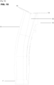
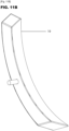
- FIGS. 11A And 11B show views of the blade (19) alone, in two orientations.
- the blade (19) may have at least one removable fixing means allowing it to be easily dismantled and reassembled in the housing (3).
- This removable fixing means may be one or more screws and/or one or more fixing clips, as well as other variants known in the field of mechanical construction.
- a removable fixing of the blade (19) makes it possible to envisage a range of several replaceable blades (19) depending on the use of the distribution device (1). Indeed, different types of agricultural products having different characteristics (dimensions, shape, adhesion, etc.) may require adapted shapes of the blade (19) for optimal efficiency.
- These adapted shapes are for example a more or less significant radius of curvature of the blade (19), a more or less progressive curvature between its two ends (for example with a radius of curvature which varies between the two ends), the general dimensions of the blade (height, width, thickness, etc.), a number of perforations of the disc (5) affected by the blade (19) on the circular path of the seeds, etc.
- FIG. 12 represents an agricultural machine (2) capable of accommodating at least one distribution device (1) having the advantageous characteristics described above.
- it is a precision seeder, also called a single-seed seeder.
- On the Figure 12 it is a seed drill with six sowing elements of the single-seed type.
- Each sowing element is equipped with at least one distribution device (1) arranged between the seed hopper and soil working and/or sowing elements which are in contact with the soil.
Landscapes
- Life Sciences & Earth Sciences (AREA)
- Soil Sciences (AREA)
- Environmental Sciences (AREA)
- Sowing (AREA)
- Pretreatment Of Seeds And Plants (AREA)
Applications Claiming Priority (1)
| Application Number | Priority Date | Filing Date | Title |
|---|---|---|---|
| FR2309518A FR3152701B1 (fr) | 2023-09-11 | 2023-09-11 | Dispositif de distribution de produit agricole amélioré |
Publications (1)
| Publication Number | Publication Date |
|---|---|
| EP4520155A1 true EP4520155A1 (de) | 2025-03-12 |
Family
ID=88965254
Family Applications (1)
| Application Number | Title | Priority Date | Filing Date |
|---|---|---|---|
| EP24197839.4A Pending EP4520155A1 (de) | 2023-09-11 | 2024-09-02 | Verbesserte vorrichtung zur verteilung landwirtschaftlicher produkte |
Country Status (3)
| Country | Link |
|---|---|
| US (1) | US20250081878A1 (de) |
| EP (1) | EP4520155A1 (de) |
| FR (1) | FR3152701B1 (de) |
Citations (3)
| Publication number | Priority date | Publication date | Assignee | Title |
|---|---|---|---|---|
| WO2010059101A1 (en) * | 2008-11-18 | 2010-05-27 | Väderstad-Verken Ab | Arrangement of a seed metering device on an agricultural machine |
| US20140182495A1 (en) * | 2013-01-02 | 2014-07-03 | Cnh America Llc | Seed Delivery System |
| US20190239425A1 (en) * | 2018-02-05 | 2019-08-08 | Deere & Company | Row unit for a seeding machine with pneumatic seed loading |
-
2023
- 2023-09-11 FR FR2309518A patent/FR3152701B1/fr active Active
-
2024
- 2024-09-02 EP EP24197839.4A patent/EP4520155A1/de active Pending
- 2024-09-10 US US18/829,406 patent/US20250081878A1/en active Pending
Patent Citations (4)
| Publication number | Priority date | Publication date | Assignee | Title |
|---|---|---|---|---|
| WO2010059101A1 (en) * | 2008-11-18 | 2010-05-27 | Väderstad-Verken Ab | Arrangement of a seed metering device on an agricultural machine |
| EP3329758A1 (de) | 2008-11-18 | 2018-06-06 | Väderstad Holding AB | Anordnung einer saatgutdosierungsvorrichtung auf einer landwirtschaftlichen maschine |
| US20140182495A1 (en) * | 2013-01-02 | 2014-07-03 | Cnh America Llc | Seed Delivery System |
| US20190239425A1 (en) * | 2018-02-05 | 2019-08-08 | Deere & Company | Row unit for a seeding machine with pneumatic seed loading |
Also Published As
| Publication number | Publication date |
|---|---|
| US20250081878A1 (en) | 2025-03-13 |
| FR3152701A1 (fr) | 2025-03-14 |
| FR3152701B1 (fr) | 2025-12-26 |
Similar Documents
| Publication | Publication Date | Title |
|---|---|---|
| EP2854499B1 (de) | Einzelkornsämaschine und kornvereinzelungsscheibe mit offenen rillen | |
| EP3813505B1 (de) | Anordnung zur ausgabe von granulatförmigen produkten | |
| EP0536768B1 (de) | Verteiler für eine Einzelkörnersämaschine | |
| EP0046709B1 (de) | Verteilvorrichtung für pneumatische Einzelkornsämaschine | |
| EP2953443B1 (de) | Einzelkornsämaschine mit wenigstens einer verbesserten säelement | |
| EP2672804B1 (de) | Verteilerkasten für einzelsämaschine mit rührklingen und sämaschine mit einem solchen kasten | |
| EP3479670A1 (de) | Öffnungsvorrichtung für sämaschine | |
| EP0037337B1 (de) | Verteilervorrichtung für Präzisionssämaschine | |
| EP4520155A1 (de) | Verbesserte vorrichtung zur verteilung landwirtschaftlicher produkte | |
| FR2566991A1 (fr) | Machine d'epandage centrifuge de produits en grains. | |
| FR2691040A1 (fr) | Dispositif régulateur de distribution des graines pour semoir. | |
| EP1430762B1 (de) | Dosiervorrichtung für eine Sämaschine | |
| EP1336332B1 (de) | Vorrichtung und Maschine zum Verteilen von Dünger oder anderem kornförmigen Material | |
| EP3300589A1 (de) | Maschine zur ausgabe durch projektion von produkten mit kurzen und langen fasersträngen | |
| EP4616692A1 (de) | Vereinzelungseinheit für eine sämaschine und zugehöriges entleerungsverfahren | |
| FR3002420A3 (fr) | Brosse pour outil de surfacage | |
| EP1038428A1 (de) | Schneidevorrichtung einer Mähmaschine | |
| EP3031312B1 (de) | Verteilungsgehäuse mit druckbeaufschlagtem bereich für einzelkornsämaschine | |
| EP4684624A1 (de) | Trennvorrichtung für ein verteilungselement und zugehörige sämaschine | |
| FR3134947A1 (fr) | Dispositif d’accélération d’au moins un élément granulaire de préférence une graine | |
| FR2570922A1 (fr) | Distributeur de graines combine a une roue a godets de plastisemeuse. | |
| FR2488480A1 (fr) | Dispositif distributeur pour semoir dit " monograine " et semoir comportant un tel dispositif | |
| FR3007741A1 (fr) | Buse de dosage pour machine de remplissage de recipients |
Legal Events
| Date | Code | Title | Description |
|---|---|---|---|
| PUAI | Public reference made under article 153(3) epc to a published international application that has entered the european phase |
Free format text: ORIGINAL CODE: 0009012 |
|
| STAA | Information on the status of an ep patent application or granted ep patent |
Free format text: STATUS: THE APPLICATION HAS BEEN PUBLISHED |
|
| AK | Designated contracting states |
Kind code of ref document: A1 Designated state(s): AL AT BE BG CH CY CZ DE DK EE ES FI FR GB GR HR HU IE IS IT LI LT LU LV MC ME MK MT NL NO PL PT RO RS SE SI SK SM TR |
|
| STAA | Information on the status of an ep patent application or granted ep patent |
Free format text: STATUS: REQUEST FOR EXAMINATION WAS MADE |
|
| 17P | Request for examination filed |
Effective date: 20250912 |