EP4520217A1 - Dispositif de boucle à déverrouillage rapide de liaison et gilet pare-balles à libération rapide - Google Patents
Dispositif de boucle à déverrouillage rapide de liaison et gilet pare-balles à libération rapide Download PDFInfo
- Publication number
- EP4520217A1 EP4520217A1 EP23822734.2A EP23822734A EP4520217A1 EP 4520217 A1 EP4520217 A1 EP 4520217A1 EP 23822734 A EP23822734 A EP 23822734A EP 4520217 A1 EP4520217 A1 EP 4520217A1
- Authority
- EP
- European Patent Office
- Prior art keywords
- buckle
- unlocking operation
- operation member
- drawstring
- connection
- Prior art date
- Legal status (The legal status is an assumption and is not a legal conclusion. Google has not performed a legal analysis and makes no representation as to the accuracy of the status listed.)
- Pending
Links
Images


Classifications
-
- F—MECHANICAL ENGINEERING; LIGHTING; HEATING; WEAPONS; BLASTING
- F41—WEAPONS
- F41H—ARMOUR; ARMOURED TURRETS; ARMOURED OR ARMED VEHICLES; MEANS OF ATTACK OR DEFENCE, e.g. CAMOUFLAGE, IN GENERAL
- F41H1/00—Personal protection gear
- F41H1/02—Armoured or projectile- or missile-resistant garments; Composite protection fabrics
-
- A—HUMAN NECESSITIES
- A44—HABERDASHERY; JEWELLERY
- A44B—BUTTONS, PINS, BUCKLES, SLIDE FASTENERS, OR THE LIKE
- A44B11/00—Buckles; Similar fasteners for interconnecting straps or the like, e.g. for safety belts
- A44B11/25—Buckles; Similar fasteners for interconnecting straps or the like, e.g. for safety belts with two or more separable parts
- A44B11/2503—Safety buckles
- A44B11/2507—Safety buckles actuated by a push-button
- A44B11/2515—Safety buckles actuated by a push-button acting parallel to the main plane of the buckle and perpendicularly to the direction of the fastening action
- A44B11/2519—Safety buckles actuated by a push-button acting parallel to the main plane of the buckle and perpendicularly to the direction of the fastening action with two buttons acting in opposite directions
-
- A—HUMAN NECESSITIES
- A44—HABERDASHERY; JEWELLERY
- A44B—BUTTONS, PINS, BUCKLES, SLIDE FASTENERS, OR THE LIKE
- A44B11/00—Buckles; Similar fasteners for interconnecting straps or the like, e.g. for safety belts
- A44B11/25—Buckles; Similar fasteners for interconnecting straps or the like, e.g. for safety belts with two or more separable parts
- A44B11/2592—Buckles; Similar fasteners for interconnecting straps or the like, e.g. for safety belts with two or more separable parts fastening by sliding in the main plane or a plane parallel to the main plane of the buckle
-
- A—HUMAN NECESSITIES
- A44—HABERDASHERY; JEWELLERY
- A44B—BUTTONS, PINS, BUCKLES, SLIDE FASTENERS, OR THE LIKE
- A44B11/00—Buckles; Similar fasteners for interconnecting straps or the like, e.g. for safety belts
- A44B11/25—Buckles; Similar fasteners for interconnecting straps or the like, e.g. for safety belts with two or more separable parts
- A44B11/26—Buckles; Similar fasteners for interconnecting straps or the like, e.g. for safety belts with two or more separable parts with push-button fastenings
- A44B11/266—Buckles; Similar fasteners for interconnecting straps or the like, e.g. for safety belts with two or more separable parts with push-button fastenings with at least one push-button acting parallel to the main plane of the buckle and perpendicularly to the direction of the fastening action
Definitions
- the present invention relates to a buckle device, and in particular, to an associated quick-release buckle device and a bulletproof quick-release vest.
- a quick-release bulletproof vest is formed by connecting a front vest plate to a back vest plate. Shoulder and waist portions of the front vest plate and the back vest plate are separately connected through connection buckles. When the vest needs to be taken off, the front vest plate and the back vest plate can be detached by unbuttoning each connection buckle. When the vest needs to be put on, connection buckles can be connected one by one. Compared with a common bulletproof vest, this quick-release bulletproof vest is more convenient to be put on and taken off, but still requires a user to unbutton the connection buckles one by one with both hands usually. Therefore, an unbuttoning method of the bulletproof vest still needs to be improved to further increase speeds of putting on and taking off the bulletproof vest.
- the present invention is intended to resolve the foregoing problem, and provides an associated quick-release buckle device and a bulletproof quick-release vest through which connection buckles at multiple different positions can be unlocked with one motion.
- the present invention provides an associated quick-release buckle device, including a first connection buckle, a second connection buckle, a quick-release buckle, a first drawstring and a second drawstring
- the first connection buckle includes a first male buckle and a first female buckle that can be locked and separated from each other
- the second connection buckle includes a second male buckle and a second female buckle that can be locked and separated from each other
- the quick-release buckle is provided with an unlocking operation member that can be operated for unlocking
- the first drawstring is connected between the first connection buckle and the quick-release buckle
- the second drawstring is connected between the second connection buckle and the quick-release buckle, where when the unlocking operation member is operated, the first connection buckle and the second connection buckle can be associated for unlocking in sequence, so that the first male buckle and the first female buckle are separated from each other and then the second male buckle and the second female buckle are separated from each other.
- the unlocking operation member includes a first unlocking operation member and a second unlocking operation member that can be pressed in opposite directions, the first unlocking operation member is connected with the first drawstring, and the second unlocking operation member is connected with the second drawstring; a first elastic member is provided between the first unlocking operation member and the quick-release buckle, a second elastic member is provided between the second unlocking operation member and the quick-release buckle, and a damping coefficient of the first elastic member is less than a damping coefficient of the second elastic member; and when the first unlocking operation member and the second unlocking operation member are pressed in opposite directions, the first connection buckle and the second connection buckle are unlocked in sequence.
- the quick-release buckle includes a shell and a base that are docked, and a partition portion is provided in the shell and/or the base; the first unlocking operation member and the second unlocking operation member are distributed on two sides of the partition portion and are spaced apart from the partition portion; the first elastic member is connected between the first unlocking operation member and the partition portion; and the second elastic member is connected between the second unlocking operation member and the partition portion.
- first unlocking operation member and the second unlocking operation member each include one pressing portion and two connection portions, and the connection portions are distributed on two sides of the pressing portion; a connection portion of the first unlocking operation member is connected with the first connection buckle through the first drawstring respectively; and a connection portion of the second unlocking operation member is connected with the second connection buckle through the second drawstring respectively.
- the pressing portion is respectively provided with a first pressing zone, a second pressing zone and a third pressing zone, and the first pressing zone and the third pressing zone are located on two sides of the second pressing zone; when first pressing zones of the first unlocking operation member and the second unlocking operation member are pressed in opposite directions, one first connection buckle can be associated for unlocking and then one second connection buckle is associated for unlocking; when third pressing zones of the first unlocking operation member and the second unlocking operation member are pressed in opposite directions, another first connection buckle can be associated for unlocking and then another second connection buckle is associated for unlocking; and when second pressing zones of the first unlocking operation member and the second unlocking operation member are pressed in opposite directions, all first connection buckles can be associated for unlocking and then all second connection buckles are associated for unlocking.
- the unlocking operation member can rotate around a fixed rotation center, a first guide surface and a second guide surface are provided on the unlocking operation member, and guiding distances of the first guide surface and the second guide surface are different;
- the first drawstring has one end connected with the unlocking operation member, and has another end protruding from the quick-release buckle along the first guide surface to be connected with the first connection buckle;
- the second drawstring has one end connected with the unlocking operation member, and has another end protruding from the quick-release buckle along the second guide surface to be connected with the second connection buckle; and when the unlocking operation member is operated to rotate around the rotation center, movement distances of the first drawstring and the second drawstring are different under guide of the first guide surface and the second guide surface, and the first connection buckle and the second connection buckle can be associated for unlocking in sequence.
- curvature of the first guide surface is greater than that of the second guide surface.
- the quick-release buckle includes a shell and a buckle base that are docked, the shell is provided with a hollow hole for movement of the unlocking operation member, a connection tab facing toward the hollow hole is provided in the buckle base, a rotation shaft is inserted into the connection tab, and the unlocking operation member is rotatably connected with the rotation shaft and can rotate around the rotation shaft.
- a returning torsion spring for driving returning of the unlocking operation member is provided between the unlocking operation member and the rotation shaft, the returning torsion spring is sleeved on the rotation shaft, and a torsion arm of the returning torsion spring is connected with the unlocking operation member, the housing and/or the buckle base.
- first male buckle and the second male buckle each are provided with a lock tongue; and the first female buckle and the second female buckle each are provided with a lock hole for inserting the lock tongue and a movably disposed locking part, the locking part can be fitted with the lock tongue penetrating through the lock hole, to engage the first male buckle with the first female buckle and engage the second male buckle with the second female buckle, and the locking part can be detached from the lock tongue under a pulling force of the first drawstring or the second drawstring to enable the first male buckle to be separated from the first female buckle and enable the second male buckle to be separated from the second female buckle.
- the locking part includes a locking portion, an actuation portion and a shoveling portion that are integrally formed or fixedly connected, the locking portion and the shoveling portion are spaced apart and disposed opposite each other, the locking portion can be engaged with the lock tongue, and the shoveling portion can drive the lock tongue to detach from the lock hole;
- the actuation portion is connected with the first drawstring or the second drawstring; and when the unlocking operation member is operated, the first drawstring and the second drawstring pull the actuation portion to enable the locking portion to detach from the lock tongue, and pull the shoveling portion to drive the lock tongue to detach from the lock hole.
- the locking part includes a locking portion, an actuation portion and a shoveling portion that can move relative to each other, the shoveling portion is movably provided on the actuation portion, a third elastic member is provided between the shoveling portion and the actuation portion, and the locking portion and the shoveling portion are spaced apart and disposed opposite each other;
- the actuation portion is connected with the first drawstring or the second drawstring; and when the unlocking operation member is operated, the first drawstring and the second drawstring pull the actuation portion to enable the shoveling portion to move to a joint portion of the lock tongue and the first female buckle or the second female buckle to tend to drive the lock tongue to detach from the lock hole; and when the actuation portion moves to a position at which the locking portion can be actuated, the locking portion is detached from the lock tongue, and the shoveling portion drives the lock tongue to detach from the lock hole.
- a second magnetic member is provided in the lock tongue
- first magnetic members are provided at positions, corresponding to the lock hole, in the first female buckle and the second female buckle
- a third magnetic member is provided on the locking portion;
- the second magnetic member can attract the first magnetic member, so that the lock tongue is aligned with and inserted into the lock hole;
- the second magnetic member can attract or repel the third magnetic member and actuate the locking portion when the lock tongue is inserted into the lock hole, so that the locking portion is engaged with the lock tongue;
- the first magnetic member can repel or attract the third magnetic member, so that the locking portion remains outside the lock hole after the lock tongue exits from the lock hole.
- a magnet base is provided at the lock hole, the second magnetic member is installed in the magnet base, and a first side opening and a second side opening communicating with the lock hole are provided on sides of the magnet base;
- the lock tongue is provided with a socket into which the locking portion can be inserted; the locking portion can be inserted into the socket through the first side opening; and the shoveling portion can be inserted between an end of the lock tongue and the magnet base through the second side opening.
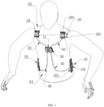
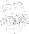
- the present invention further provides a bulletproof quick-release vest, including a front vest plate and a back vest plate, and further including the associated quick-release buckle device according to any one of claims 1 to 14, where shoulder portions on one side or two sides of the front vest plate and the back vest plate are detachably connected through the second connection buckle; waist portions on one side or two sides of the front vest plate and the back vest plate are detachably connected through the first connection buckle; the quick-release buckle is provided on the front vest plate; the first drawstring and the second drawstring are provided on the front vest plate; and when the quick-release buckle is operated, the first drawstring and the second drawstring can associate the first connection buckle with the second connection buckle for unlocking in sequence, so that waist portions of the front vest plate and the back vest plate are first unlocked and then shoulder portions of the front vest plate and the back vest plate are unlocked.
- a bulletproof quick-release vest including a front vest plate and a back vest plate, and further including the associated quick-release buckle device according to any one of claims 1 to 14, where shoulder portions
- first connection buckle and/or the second connection buckle are or is provided with a manual unlocking operation portion, and when the manual unlocking operation portion is operated, the current first connection buckle and/or the second connection buckle are or is unlocked, so that the waist portions and/or the shoulder portions of the front vest plate and the back vest plate are unlocked.
- the associated quick-release buckle device in the present invention includes a quick-release buckle, a first connection buckle, a second connection buckle, a first drawstring and a second drawstring, the quick-release buckle is associated with the first connection buckle through the first drawstring, the quick-release buckle is associated with the second connection buckle through the second drawstring, the first connection buckle and the second connection buckle can be associated for unlocking in sequence by operating the quick-release buckle, so that connection buckles at multiple different positions are unlocked through one motion.
- a user can operate the associated quick-release buckle device in the present invention with only one hand to complete unlocking of the multiple connection buckles, and therefore, the associated quick-release buckle device is easy to unlock, better customized, and very convenient to use.
- connection buckles at the waist and the shoulder can be unlocked in sequence by pressing the quick-release buckle in front of the chest, to rapidly put on or take off the bulletproof vest, and therefore, the bulletproof vest is very convenient to be put on and taken off and better satisfies use needs of the user.
- the associated quick-release buckle device in the present invention has characteristics of a novel structure and practical functions, and therefore, should be vigorously promoted due to its great practicability.
- first connection buckle 10 first male buckle 101, first female buckle 102, second connection buckle 20, second male buckle 201, second female buckle 202, quick-release buckle 30, unlocking operation member 31, first unlocking operation member 311, second unlocking operation member 312, pressing portion 313, first pressing zone 3131, second pressing zone 3132, third pressing zone 3133, connection portion 314, first guide surface 315, second guide surface 316, first drawstring hole 317, second drawstring hole 318, first rotation shaft hole 319, torsion spring groove 3110, clamping groove 3111, cover groove 3112, cover 3113, first elastic member 33, second elastic member 34, shell 35, hollow hole 351, passage groove 352, base 36, partition portion 361, buckle base 37, connection tab 371, second rotation shaft hole 372, buckle hole 373, rotation shaft 38, returning torsion spring 39, torsion arm 391, third drawstring hole 310, fourth drawstring hole 320, installation base 330, accommodation groove 3301, insertion opening 3302, restraint portion 3303, positioning portion 3304, elastic pressing portion 3305, positioning bulge
- an associated quick-release buckle device in the present invention includes a first connection buckle 10, a second connection buckle 20, a quick-release buckle 30, a first drawstring 40 and a second drawstring 50.
- the first connection buckle 10 and the second connection buckle 20 are respectively configured to connect a to-be-connected object, for example, a front vest plate 61 and a back vest plate 62 of a bulletproof vest.
- the quick-release buckle 30 is used for unlocking
- the first drawstring 40 and the second drawstring 50 are used for pulling the first connection buckle 10 and the second connection buckle 20 to implement unlocking
- the first drawstring 40 is connected between the first connection buckle 10 and the quick-release buckle 30
- the second drawstring 50 is connected between the second connection buckle 20 and the quick-release buckle 30.
- first connection buckle 10 and the second connection buckle 20 are configured to be installed at different positions.
- first connection buckle 10 is configured to be installed at a waist portion of the bulletproof vest
- second connection buckle 20 is configured to be installed at a shoulder portion of the bulletproof vest.
- the numbers of first connection buckles 10 and second connection buckles 20 can be set according to needs.
- the first connection buckle 10 and the second connection buckle 20 can be connection buckles having the same structure or different structures and can be specifically set according to needs. Shapes of the first connection buckle 10 and the second connection buckle 20 can be same or different and can be specifically set according to needs.
- the first connection buckle 10 and the second connection buckle 20 can be magnetic buckles or non-magnetic buckles, for example, insertion buckles and can be specifically set according to needs.
- the first connection buckle 10 includes a first male buckle 101 and a first female buckle 102.
- the first male buckle 101 and the first female buckle 102 can be locked together or separated from each other.
- the second connection buckle 20 includes a second male buckle 201 and a second female buckle 202.
- the second male buckle 201 and the second female buckle 202 can be locked together or separated from each other.
- Structures of the first male buckle 101 and the second male buckle 201 can be same or different and can be specifically set according to needs.
- Structures of the first female buckle 102 and the second female buckle 202 can be same or different and can be specifically set according to needs.
- the quick-release buckle 30 is provided with an unlocking operation member 31 that can be operated for unlocking.
- the first drawstring 40 is connected between the first connection buckle 10 and the quick-release buckle 30. Specifically, the first drawstring 40 is connected between the first female buckle 102 and the unlocking operation member 31. When the unlocking operation member 31 is operated, the first drawstring 40 is pulled, which can actuate the first connection buckle 10, so that the first connection buckle 10 is unlocked.
- the number of first drawstrings 40 is consistent with the number of first connection buckles 10.
- Each first connection buckle 10 can be associated with the quick-release buckle 30 through one first drawstring 40.
- the second drawstring 50 is connected between the second connection buckle 20 and the quick-release buckle 30.
- the second drawstring 50 is connected between the second female buckle 202 and the unlocking operation member 31.
- the unlocking operation member 31 When the unlocking operation member 31 is operated, the second drawstring 50 is pulled, which can actuate the second connection buckle 20, so that the second connection buckle 20 is unlocked.
- the number of second drawstrings 50 is consistent with the number of second connection buckles 20.
- Each second connection buckle 20 can be associated with the quick-release buckle 30 through one second drawstring 50.
- Well-known rope structures such as wire ropes can be selected as the first drawstring 40 and the second drawstring 50.
- the first drawstring 40 and the second drawstring 50 are preferably sheath structures, including an external sheath 71 and a core drawstring 72 inside the sheath 71, and the core drawstring 72 can be moved relative to the sheath 71.
- Core drawstrings 72 in the first drawstring 40 and the second drawstring 50 are connected with the unlocking operation member 31. When the unlocking operation member 31 is operated, the core drawstring 72 is pulled and moved relative to the fixed sheath 71.
- the first drawstring 40 and the second drawstring 50 are pulled simultaneously, but the first drawstring 40 and the second drawstring 50 are pulled to different degrees, which can actuate the first connection buckle 10 and the second connection buckle 20 to be unlocked in sequence:
- the first connection buckle 10 is first unlocked, and after the first male buckle 101 and the second female buckle 202 are separated from each other, the second connection buckle 20 is further unlocked, so that the second male buckle 201 and the second female buckle 202 are separated from each other.
- unlocking operation members 31 include a first unlocking operation member 311 and a second unlocking operation member 312 that can be pressed in opposite directions.
- the first unlocking operation member 311 and the second unlocking operation member 312 are movably provided on the quick-release buckle 30.
- the first unlocking operation member 311 is connected with an end of the first drawstring 40
- the second unlocking operation member 312 is connected with an end of the second drawstring 50.
- the first elastic member 33 is provided between the first unlocking operation member 311 and the quick-release buckle 30, a second elastic member 34 is provided between the second unlocking operation member 312 and the quick-release buckle 30, and a damping coefficient of the first elastic member 33 is less than a damping coefficient of the second elastic member 34.
- first elastic member 33 and the second elastic member 34 are also used for returning of the first unlocking operation member 311 and the second unlocking operation member 312:
- first elastic member 33 and the second elastic member 34 are compressed, and when the first unlocking operation member 311 and the second unlocking operation member 312 are released, to recover their original states, the first elastic member 33 and the second elastic member 34 can actuate the first unlocking operation member 311 and the second unlocking operation member 312 to return.
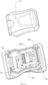
- the quick-release buckle 30 may include a shell 35 and a base 36 that are docked, and a partition portion 361 is provided in the shell 35 and/or the base 36.
- the first unlocking operation member 311 and the second unlocking operation member 312 are distributed on two sides of the partition portion 361, and the first unlocking operation member 311 and the second unlocking operation member 312 are respectively spaced apart from the partition portion 361.
- the first elastic member 33 is connected between the first unlocking operation member 311 and the partition portion 361
- the second elastic member 34 is connected between the second unlocking operation member 312 and the partition portion 361.
- the first unlocking operation member 311 and the second unlocking operation member 312 each include one pressing portion 313 and two connection portions 314.
- the connection portions 314 are distributed on two sides of the pressing portion 313.
- the pressing portion 313 and the connection portion 314 can be integrally formed or fixedly connected.
- the pressing portion 313 and the connection portion 314 are preferably integrally formed.
- the pressing portion 313 is used for pressing by a user to implement unlocking.
- connection portion 314 is configured to connect the first drawstring 40 or the second drawstring 50, a connection portion 314 of the first unlocking operation member 311 is connected with the first connection buckle 10 through the first drawstring 40, and a connection portion 314 of the second unlocking operation member 312 is connected with the second connection buckle 20 through the second drawstring 50.
- all second connection buckles 20 can be associated for unlocking after all first connection buckles 10 are associated for unlocking.
- the pressing portion 313 is respectively provided with a first pressing zone 3131, a second pressing zone 3132 and a third pressing zone 3133.
- the first pressing zone 3131 and the third pressing zone 3133 are located on two sides of the second pressing zone 3132.
- first connection buckle 10 When first pressing zones 3131 of the first unlocking operation member 311 and the second unlocking operation member 312 are pressed in opposite directions, one first connection buckle 10 can be associated for unlocking and then one second connection buckle 20 is associated for unlocking.
- first connection buckle 10 on a left waist portion of the bulletproof vest can be associated for unlocking first, and then a second connection buckle 20 on a left shoulder portion is associated for unlocking.
- first connection buckle 10 can be associated for unlocking and then another second connection buckle 20 is associated for unlocking.
- first connection buckle 10 on a right waist portion of the bulletproof vest can be associated for unlocking first, and then a second connection buckle 20 on a right shoulder portion is associated for unlocking.
- first connection buckles 10 can be associated for unlocking and then all second connection buckles 20 are associated for unlocking. That is, first connection buckles 10 on left and right waist portions are associated for unlocking first, and then second connection buckles 20 on left and right shoulder portions are associated for unlocking.
- the first elastic member 33 and the second elastic member 34 are disposed between the connection portion 314 and the partition portion 361, so that the first drawstring 40 or the second drawstring 50 can be always associated when the first pressing zone 3131, the second pressing zone 3132 and the third pressing zone 3133 are pressed.
- the first elastic member 33 has an end abutting against the connection portion 314 of the first unlocking operation member 311 and has another end abutting against the partition portion 361; and the second elastic member 34 has an end abutting against the connection portion 314 of the second unlocking operation member 312 and has another end abutting against the partition portion 361.
- the unlocking operation member 31 can rotate around a fixed rotation center.
- a first guide surface 315 and a second guide surface 316 are provided on the unlocking operation member 31. Guiding distances of the first guide surface 315 and the second guide surface 316 are different, so that the first drawstring 40 and the second drawstring 50 travel different distances.
- the first drawstring 40 is connected with the unlocking operation member 31, and is connected with the first connection buckle 10 along the first guide surface 315.
- the second drawstring 50 is connected with the unlocking operation member 31, and is connected with the second connection buckle 20 along the second guide surface 316.
- the first connection buckle 10 and the second connection buckle 20 can be associated for unlocking in sequence.
- curvature of the first guide surface 315 is greater than that of the second guide surface 316.
- a pulling degree of the first drawstring 40 is greater than that of the second drawstring 50, so that the first connection buckle 10 connected with the first drawstring 40 can be unlocked prior to the second connection buckle 20 connected with the second drawstring 50, thereby unlocking the first connection buckle 10 and the second connection buckle 20 successively.
- a curved surface can be set as the first guide surface 315
- a plane can be set as the second guide surface 316
- the first guide surface 315 is more protuberant than the second guide surface 316, so that the first connection buckle 10 and the second connection buckle 20 can be unlocked in sequence.
- the first drawstring hole 317 and the second drawstring hole 318 are provided on the unlocking operation member 31.
- the first drawstring hole 317 is adjacent to the first guide surface 315
- the second drawstring hole 318 is adjacent to the second guide surface 316.
- the first drawstring 40 has one end confined to the first drawstring hole 317 and has another end connected with the first connection buckle 10 along the first guide surface 315.
- the second drawstring 50 has one end confined to the second drawstring hole 318 and has another end connected with the second connection buckle 20 along the second guide surface 316. In this case, when the unlocking operation member 31 is rotated, the first drawstring 40 and the second drawstring 50 move along the first guide surface 315 and the second guide surface 316.
- first drawstring hole 317 and the second drawstring hole 318 are located at the same ends of the first guide surface 315 and the second guide surface 316, and the first drawstring 40 and the second drawstring 50 are extended from the same end of the unlocking operation member 31 to be respectively connected with the first connection buckle 10 and the second connection buckle 20, so that drawstring distribution can be neater, which facilitates sewing and fixation of the drawstrings.
- the number of unlocking operation members 31 can be set according to needs. As shown in FIG. 6 , one unlocking operation member 31 can be disposed. As shown in FIG. 9 , multiple unlocking operation members 31 can be disposed. When the multiple unlocking operation members 31 are disposed, the first guide surface 315 and the second guide surface 316 are disposed on each unlocking operation member 31.
- the unlocking operation member 31 in order that the unlocking operation member 31 rotates around a fixed rotation center, the unlocking operation member 31 is rotatably connected within the housing.
- the housing includes a shell 35 and a buckle base 37 that are docked. Installation space for installing the unlocking operation member 31 is formed between the shell 35 and the buckle base 37.
- the shell 35 is provided with a hollow hole 351 for movement of the unlocking operation member 31, and a connection tab 371 facing toward the hollow hole 351 is provided in the buckle base 37.
- a shape of the connection tab 371 is not limited, a second rotation shaft hole 372 is provided in the connection tab 371, and a rotation shaft 38 is inserted into the second rotation shaft hole 372.
- the rotation shaft 38 can be inserted into the buckle base 37 or the shell 35, and can be specifically disposed according to needs. Preferably, the two ends of the rotation shaft 38 are inserted into the shell 35.
- the unlocking operation member 31 is provided with a first rotation shaft hole 319, and the rotation shaft 38 is sleeved into the first rotation shaft hole 319 and located at the hollow hole 351. The unlocking operation member 31 can rotate around the rotation shaft 38. In this way, the rotation shaft 38 forms the rotation center of the unlocking operation member 31.
- a returning torsion spring 39 is provided between the unlocking operation member 31 and the rotation shaft 38.
- the returning torsion spring 39 is sleeved on the rotation shaft 38, and a torsion arm 391 of the returning torsion spring 39 is connected with the unlocking operation member 31, the housing and/or the buckle base 37.
- the unlocking operation member 31 tightly fits the buckle base 37 by default.
- the unlocking operation member 31 is pulled outward away from the buckle base 37, to rotate the unlocking operation member 31, so that the first drawstring 40 and the second drawstring 50 can be pulled to different degrees.
- the torsion arm 391 of the returning torsion spring 39 is in a stressed state.
- the torsion arm 391 of the returning torsion spring 39 returns to drive the unlocking operation member 31 to move toward the buckle base 37, so that the unlocking operation member 31 automatically returns.
- structures of the first male buckle 101 and the second male buckle 201 can be same or different and can be specifically set according to needs.
- Structures of the first female buckle 102 and the second female buckle 202 can be same or different and can be specifically set according to needs.
- the first male buckle 101 and the second male buckle 201 each are provided with a lock tongue 81; and the first female buckle 102 and the second female buckle 202 each are provided with a lock hole 921 for inserting the lock tongue 81 and a movably disposed locking part 93.
- the locking part 93 can fit the lock tongue 81, so that the first male buckle 101 and the first female buckle 102 are locked together and the second male buckle 201 and the second female buckle 202 are locked together.
- the locking part 93 is respectively connected with the corresponding first drawstring 40 or second drawstring 50, and can be detached from the lock tongue 81 under a pulling force of the corresponding first drawstring 40 or second drawstring 50, so that the first male buckle 101 and the first female buckle 102 are separated from each other and the second male buckle 201 and the second female buckle 202 are separated from each other.
- the locking part 93 includes a locking portion 931, an actuation portion 932 and a shoveling portion 933 that are integrally formed or fixedly connected.
- the locking portion 931, the actuation portion 932 and the shoveling portion 933 cannot move relative to each other.
- the locking portion 931 and the shoveling portion 933 are spaced apart and disposed opposite each other.
- the locking portion 931 is configured to be engaged with the lock tongue 81, so that a male buckle structure 80 is maintained in a female buckle structure 90.
- the shoveling portion 933 is configured to drive the lock tongue 81 to detach from the lock hole 921.
- the actuation portion 932 is connected with the corresponding first drawstring 40 and second drawstring 50, to drive the locking portion 931 and the shoveling portion 933 to move under a pulling force of the first drawstring 40 and the second drawstring 50.
- the first drawstring 40 and the second drawstring 50 pull the actuation portion 932, to drive the locking portion 931 and the shoveling portion 933 to move, movement of the locking portion 931 drives the locking portion 931 to detach from the lock tongue 81, and movement of the shoveling portion 933 drives the lock tongue 81 to detach from the lock hole 921.
- the locking part includes a locking portion 931, an actuation portion 932 and a shoveling portion 933 that can move relative to each other.
- the shoveling portion 933 is movably provided on the actuation portion 932, a third elastic member 934 is provided between the shoveling portion 933 and the actuation portion 932, and the locking portion 931 and the shoveling portion 933 are spaced apart and disposed opposite each other.
- the locking portion 931 is configured to be engaged with the lock tongue 81, so that a male buckle structure 80 is maintained in a female buckle structure 90.
- the shoveling portion 933 is configured to drive the lock tongue 81 to detach from the lock hole 921.
- the actuation portion 932 is connected with the corresponding first drawstring 40 and second drawstring 50, to drive the locking portion 931 and the shoveling portion 933 to move under a pulling force of the first drawstring 40 and the second drawstring 50.
- the first drawstring 40 and the second drawstring 50 pull the actuation portion 932 to enable the shoveling portion 933 to first move to a joint portion of the lock tongue 81 and the first female buckle 102 or the second female buckle 202 to tend to drive the lock tongue 81 to detach from the lock hole 921.
- the shoveling portion 933 only acts on the lock tongue 81, and because the lock tongue 81 is still engaged with the locking portion 931 at this moment, the shoveling portion 933 cannot directly drive the lock tongue 81 to detach from the lock hole 921.
- the actuation portion 932 moves, under a pulling force of the corresponding first drawstring 40 or second drawstring 50, to a position at which the locking portion 931 can be actuated, the locking portion 931 is detached from the lock tongue 81, and the shoveling portion 933 can drive the lock tongue 81 to detach from the lock hole 921.
- a second magnetic member 82 is provided in the lock tongue 81, first magnetic members 94 are provided at positions, corresponding to the lock hole 921, in the first female buckle 102 and the second female buckle 202, and a third magnetic member 95 is provided on the locking portion 931;
- the second magnetic member 82 can attract the first magnetic member 94, so that the lock tongue 81 is aligned with and inserted into the lock hole 921;
- the second magnetic member 82 can attract or repel the third magnetic member 95 and actuate the locking portion 931 when the lock tongue 81 is inserted into the lock hole 921, so that the locking portion 931 is engaged with the lock tongue 81;
- the first magnetic member 94 can repel or attract the third magnetic member 95, so that the locking portion 931 remains outside the lock hole 921 after the lock tongue 81 exits from the lock hole 921.
- a magnet base 922 is provided at the lock hole 921, a first magnetic member 94 is installed in the magnet base 922, and a first side opening 9222 and a second side opening 9223 communicating with the lock hole 921 are provided on sides of the magnet base 922.
- the lock tongue 81 is provided with a socket 811 into which the locking portion 931 can be inserted; the locking portion 931 can be inserted into the socket 811 through the first side opening 9222; and the shoveling portion 933 can be inserted between an end of the lock tongue 81 and the magnet base 922 through the second side opening 9223.
- the associated quick-release buckle device in the present invention is formed, and operating the quick-release buckle 30 can unlock the first connection buckle 10 and the second connection buckle 20 successively, to achieve an effect of unlocking multiple connection buckles with one motion, making the associated quick-release buckle device convenient for the user to use.
- the shell 35 and the base 36 are docked, and the base 36 can be configured to be fixed on a used object such as a bulletproof vest. Shapes of the shell 35 and the base 36 are not limited.
- the shell 35 and the base 36 are docked to form an installation space that can be used to install the first unlocking operation member 311, the second unlocking operation member 312, the first elastic member 33 and the second elastic member 34.
- a partition portion 361 is provided in the base 36 and/or the shell 35.
- the partition portion 361 is provided at the center of the base 36.
- the partition portion 361 is integrated with the base 36 and protrudes from a surface of the base 36.
- the first unlocking operation member 311 and the second unlocking operation member 312 are movably disposed between the shell 35 and the base 36, and the first unlocking operation member 311 and the second unlocking operation member 312 are distributed on two sides of the partition portion 361.
- the first unlocking operation member 311 and the second unlocking operation member 312 each include one pressing portion 313 and two connection portions 314.
- the connection portion 314 is formed by extending ends of the pressing portion 313 toward two sides of the pressing portion 313, so that the pressing portion 313 and the connection portion 314 form a T-shape structure.
- the pressing portion 313 is used for pressing and is partially or completely located outside the shell 35 and the base 36.
- the connection portion 314 is located between the shell 35 and the base 36.
- connection portions 314 are respectively disposed in the connection portions 314 and are configured to pull and tie a wire rope.
- the two connection portions 314 of the first unlocking operation member 311 can be connected with two first drawstrings 40 respectively through rope holes.
- the two connection portions 314 of the second unlocking operation member 312 can be connected with two second drawstrings 50 respectively through rope holes.
- the first elastic member 33 and the second elastic member 34 are in a compressed state or a natural state by default.
- the first elastic member 33 and the second elastic member 34 can be compressed, and a compression volume of the first elastic member 33 is greater than that of the second elastic member 34.
- the two first connection buckles 10 are first unlocked, and then the two second connection buckles 20 are unlocked. That is, 2 connection buckles can be simultaneously associated for unlocking by applying pressing forces in opposite directions.
- the quick-release buckle 30 in this embodiment includes a shell 35, a base 36, a first unlocking operation member 311, a second unlocking operation member 312, a first elastic member 33 and a second elastic member 34.
- the shell 35 and the base 36 are docked, and the base 36 can be configured to be fixed on a used object such as a bulletproof vest. Shapes of the shell 35 and the base 36 are not limited.
- the shell 35 and the base 36 are docked to form an installation space that can be used to install the first unlocking operation member 311, the second unlocking operation member 312, the first elastic member 33 and the second elastic member 34.
- the first unlocking operation member 311 and the second unlocking operation member 312 are movably disposed between the shell 35 and the base 36, and the first unlocking operation member 311 and the second unlocking operation member 312 are distributed on two sides of the partition portion 361.
- the first unlocking operation member 311 and the second unlocking operation member 312 each include one pressing portion 313 and two connection portions 314.
- connection portion 314 is formed by extending ends of the pressing portion 313 toward two sides of the pressing portion 313, so that the pressing portion 313 and the connection portion 314 form a T-shape structure.
- the connection portion 314 is located between the shell 35 and the base 36.
- the pressing portion 313 is used for pressing and is partially or completely located outside the shell 35 and the base 36.
- connection portions 314 are respectively disposed in the connection portions 314 and are configured to pull and tie a wire rope.
- the two connection portions 314 of the first unlocking operation member 311 can be connected with two first drawstrings 40 respectively through rope holes.
- the two connection portions 314 of the second unlocking operation member 312 can be connected with two second drawstrings 50 respectively through rope holes.
- the pressing portion 313 is respectively provided with a first pressing zone 3131, a second pressing zone 3132 and a third pressing zone 3133.
- the first pressing zone 3131 and the third pressing zone 3133 are distributed on two sides of the second pressing zone 3132.
- the first pressing zone 3131 and the third pressing zone 3133 are symmetrical relative to the second pressing zone 3132, and the second pressing zone 3132 is located at the center of the pressing portion 313.
- corresponding signs can be disposed at corresponding positions of the first pressing zone 3131, the second pressing zone 3132 and the third pressing zone 3133.
- the sign may be a word sign, a pattern sign or a graph sign.
- the first pressing zone 3131, the second pressing zone 3132 and the third pressing zone 3133 in a slightly concave shape are disposed.
- the first elastic member 33 and the second elastic member 34 are movably disposed between the shell 35 and the base 36.
- Two first elastic members 33 are provided and each have an end abutting against the connection portion 314 of the first unlocking operation member 311 respectively and have another end abutting against the partition portion 361 respectively.
- Two second elastic members 34 are provided and each have an end abutting against the connection portion 314 of the second unlocking operation member 312 respectively and have another end abutting against the partition portion 361 respectively.
- springs are selected as the first elastic member 33 and the second elastic member 34, a damping coefficient of the first elastic member 33 is smaller than that of the second elastic member 34, and a compression degree of the first elastic member 33 is greater than that of the second elastic member 34 under equivalent pressure.
- the first elastic member 33 and the second elastic member 34 are in a compressed state or a natural state by default. When the first unlocking operation member 311 and the second unlocking operation member 312 are pressed in opposite directions, the first elastic member 33 and the second elastic member 34 can be compressed, and a compression volume of the first elastic member 33 is greater than that of the second elastic member 34.
- the entire first unlocking operation member 311 moves toward the partition portion 361, to ensure that displacement degrees of the two first drawstrings 40 are consistent or basically the same, so that two corresponding first connection buckles 10 are associated for unlocking.
- the entire second unlocking operation member 312 also moves toward the partition portion 361, to ensure that displacement degrees of the two second drawstrings 50 are consistent or basically the same, so that two corresponding second connection buckles 20 are associated for unlocking.
- the two first connection buckles 10 are unlocked prior to the two second connection buckles 20, thereby achieving an effect of unlocking the first connection buckle 10 and the second connection buckle 20 in sequence.
- connection portion 314 closer to the first pressing zone 3131 moves sufficient distance toward the partition portion 361 to associate the corresponding first drawstring 40 or second drawstring 50 to cause sufficient displacement, so that the first connection buckle 10 and the second connection buckle 20 are pulled for unlocking; and a connection portion 314 farther away from the first pressing zone 3131 remains unmoved or cannot cause sufficient displacement for associating the first connection buckle 10 and the second connection buckle 20 for unlocking. Therefore, when the first pressing zones 3131 of the first unlocking operation member 311 and the second unlocking operation member 312 are pressed in the opposite directions, one first connection buckle 10 and one second connection buckle 20 can be associated for unlocking in sequence.
- connection portion 314 closer to the third pressing zone 3133 moves sufficient distance toward the partition portion 361 to associate the corresponding first drawstring 40 or second drawstring 50 to cause sufficient displacement, so that the first connection buckle 10 and the second connection buckle 20 are pulled for unlocking; and a connection portion 314 farther away from the third pressing zone 3133 remains unmoved or cannot cause sufficient displacement for associating the first connection buckle 10 and the second connection buckle 20 for unlocking. Therefore, when the third pressing zones 3133 of the first unlocking operation member 311 and the second unlocking operation member 312 are pressed in the opposite directions, another first connection buckle 10 and another second connection buckle 20 can be associated for unlocking in sequence.
- first connection buckles 10 and second connection buckles 20 can be associated for unlocking in sequence by pressing second pressing zones 3132 in opposite directions, but also the single first connection buckle 10 and second connection buckle 20 can be associated for unlocking in sequence by pressing the first pressing zone 3131 and the second pressing zone 3132 in opposite directions, thereby satisfying use needs in particular scenarios.
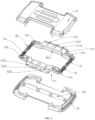
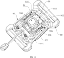
- the quick-release buckle 30 in this embodiment includes an unlocking operation member 31, a housing and an installation base 330.
- One unlocking operation member 31 is provided and one first drawstring 40 and one second drawstring 50 are separately provided.
- the unlocking operation member 31 is integrally formed and is a block-shaped structure.
- First rotation shaft holes 319 are provided in middle and lower parts of the unlocking operation member 31 and are configured to be rotatably connected with the rotation shaft 38.
- a first guide surface 315 and a second guide surface 316 are provided at the back of the unlocking operation member 31. Distances along the first guide surface 315 and the second guide surface 316 are different.
- the first drawstring hole 317 and the second drawstring hole 318 are provided on the unlocking operation member 31.
- the first drawstring hole 317 and the second drawstring hole 318 are at the same height and are spaced apart from each other.
- Through holes can be preferably set as the first drawstring hole 317 and the second drawstring hole 318, to facilitate threading.
- the number of first drawstring holes 317 is consistent with the number of first drawstrings 40, and in this embodiment, one first drawstring hole 317 is disposed.
- the number of second drawstring holes 318 is consistent with the number of second drawstrings 50, and in this embodiment, one second drawstring hole 318 is disposed.
- Shapes of the first drawstring hole 317 and the second drawstring hole 318 are not limited, provided that the ends of the first drawstring 40 and the second drawstring 50 can be restrained to connect the first drawstring 40 and the second drawstring 50 with the unlocking operation member 31.
- the first drawstring hole 317 is adjacent to the first guide surface 315, so that the first drawstring 40 is extended outward along the first guide surface 315.
- the second drawstring hole 318 is adjacent to the second guide surface 316, so that the second drawstring 50 is extended outward along the second guide surface 316.
- a plane is set as the first guide surface 315
- a curved surface is set as the second guide surface 316
- the second guide surface 316 is more protuberant than the first guide surface 315, so that distances along the first guide surface 315 and the second guide surface 316 are different and curvature of the first guide surface 315 is greater than that of the second guide surface 316.
- a torsion spring groove 3110 is disposed on one or two sides of the unlocking operation member 31.
- the torsion spring groove 3110 communicates with the first rotation shaft hole 319, and a clamping groove 3111 abutting against the torsion arm 391 of the torsion spring is disposed in a side wall of the torsion spring groove 3110.
- a rope hole can also be disposed at one end, farther away from the first rotation shaft hole 319, of the unlocking operation member 31, so that the rope can be disposed and the user easily drives the unlocking operation member 31 to rotate by pulling the rope.
- a cover groove 3112 is disposed on one side, farther away from the first guide surface 315 and the second guide surface 316, of the unlocking operation member 31, and the cover groove 3112 communicates with the first drawstring hole 317 and the second drawstring hole 318.
- a detachable cover 3113 is installed in the cover groove 3112. The cover 3113 can seal one end of the first drawstring hole 317 and the second drawstring hole 318.
- the housing includes a shell 35 and a buckle base 37 that are docked.
- the docking between the shell 35 and the buckle base 37 can be a positioning connection through a positioning column and is not necessarily a tight connection.
- several protuberant positioning columns are disposed on one side, facing toward the buckle base 37, of the shell 35
- several positioning holes are disposed on one side, facing toward the shell 35, of the buckle base 37
- the shell 35 and the buckle base 37 can be docked by inserting the positioning columns into the positioning holes.
- the shell 35 and the buckle base 37 are not fastened, to facilitate disassembly and assembly.
- the shell 35 is provided with hollow holes 351 occupying a large area, and the area of the hollow holes 351 matches the shape of the unlocking operation member 31, to allow for activity of the unlocking operation member 31.
- connection tab 371 is provided on the buckle base 37.
- the connection tab 371 is convex and faces toward the hollow hole 351 in the shell 35.
- the number of connection tabs 371 can be set according to needs.
- a second rotation shaft hole 372 is provided in the connection tab 371.
- the rotation shaft 38 is inserted into the second rotation shaft hole 372 of the connection tab 371, and two ends of the rotation shaft 38 are lapped on the shell 35.
- the unlocking operation member 31 is rotatably connected with the rotation shaft 38 through the first rotation shaft hole 319 and can rotate around the rotation shaft 38.
- the rotation center of the unlocking operation member 31 is formed at a position at which a central axis of the rotation shaft 38 is located.
- the unlocking operation member 31 when the unlocking operation member 31 is rotatably connected with the rotation shaft 38, the first guide surface 315 and the second guide surface 316 on the unlocking operation member 31 face toward the buckle base 37, and the unlocking operation member 31 can rotate away from the buckle base 37.
- the returning torsion spring 39 is sleeved on the rotation shaft 38 and is located in the torsion spring groove 3110.
- the torsion arm 391 of the returning torsion spring 39 is located in the clamping groove 3111.
- the third drawstring hole 310 and the fourth drawstring hole 320 are provided in the bottom of the housing.
- the third drawstring hole 310 is located at one end, opposite the first drawstring hole 317, of the first guide surface 315
- the fourth drawstring hole 320 is located at one end, opposite the second drawstring hole 318, of the second guide surface 316.
- the third drawstring hole 310 and the fourth drawstring hole 320 penetrate the housing throughout.
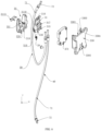
- the first drawstring 40 and the second drawstring 50 are both sheath structures, an end of the core drawstring 72 of the first drawstring 40 is disposed in the first drawstring hole 317, an end of the sheath 71 of the first drawstring 40 is disposed in the third drawstring hole 310, and the core drawstring 72 between the end of the core drawstring 72 of the first drawstring 40 and the end of the sheath 71 partially passes through the first guide surface 315.
- An end of the core drawstring 72 of the second drawstring 50 is disposed in the second drawstring hole 318, an end of the sheath 71 of the second drawstring 50 is disposed in the fourth drawstring hole 320, and the core drawstring 72 between the end of the core drawstring 72 of the second drawstring 50 and the end of the sheath 71 partially passes through the second guide surface 316.
- the installation base 330 is configured to install the quick-release buckle 30 onto equipment such as a bulletproof vest.
- the installation base 330 is provided with a screw hole for fixing the installation base 330 at a use position.
- an accommodation groove 3301 is provided in the installation base 330.
- One end of the accommodation groove 3301 is opened to form an insertion opening 3302.
- Restraint portions 3303 spaced apart from the bottom of the accommodation groove 3301 are provided on two sides of the accommodation groove 3301.
- the restraint portions 3303 are spaced apart from each other to form a first opening.
- a direction of the first opening is consistent with an opening direction of the hollow hole 351 and perpendicular to a direction of the insertion hole 3302.
- a shape and a size of the accommodation groove 3301 match a shape and a size of the housing.
- the housing may be inserted into the accommodation groove 3301 through the insertion opening 3302 and is restrained by the restraint portion 3303, so that the housing is confined to the accommodation groove 3301. Because the shell 35 of the housing and the buckle base 37 are not fastened, when the housing is installed into the accommodation groove 3301, the restraint portion 3303 can also tightly compress the shell 35 and the buckle base 37 to avoid loosening.
- a passage groove 352 is provided in the surface, facing toward the restraint portion 3303, of the shell 35, and a protruding positioning portion 3304 is provided on the restraint portion 3303.
- the positioning portion 3304 fits the passage groove 352, and has an extension direction consistent with the insertion direction of the housing.
- the positioning portion 3304 fits the passage groove 352, which can facilitate linear and smoother movement of the housing.
- an elastic pressing portion 3305 is provided at the bottom of the accommodation groove 3301, that is, one end opposite the insertion opening 3302.
- the elastic pressing portion 3305 has one end connected with the installation base 330 and has another elastic end extended to form a cantilever end.
- a hole can be provided between the installation base 330 and the elastic pressing portion 3305, so that one end of the elastic pressing portion 3305 forms the cantilever end and the elastic pressing portion 3305 can further have elasticity and be pressed.
- a shape of the elastic pressing portion 3305 is not limited.
- a positioning bulge portion 3306 is provided on the elastic pressing portion 3305.
- a buckle hole 373 is provided in the buckle base 37.
- a first guide slope 3307 is provided on the positioning bulge portion 3306.
- the first guide slope 3307 faces toward the insertion opening 3302 and has one end adjacent to the bottom of the accommodation groove 3301 and another end higher than the bottom of the accommodation groove 3301.
- a second guide slope matching the first guide slope 3307 can be provided in the buckle hole 373. An inclination manner of the second guide slope is consistent with that of the first guide slope 3307.
- the housing not only easily presses against the elastic pressing portion 3305, but also easily reversely detaches from the accommodation groove 3301.
- the elastic pressing portion 3305 is pressed, to remove the positioning bulge portion 3306 from the buckle hole 373, so that the housing can be moved along the direction of the insertion opening 3302 to be removed from the accommodation groove 3301.
- the quick-release buckle 30 in this embodiment is formed:
- the unlocking operation member 31 is rotatably connected with the rotation shaft 38, the rotation shaft 38 is installed on the connection tab 371 of the buckle base 37, and the buckle base 37 is docked to the shell 35 and installed in the accommodation groove 3301 of the installation base 330.
- the first drawstring 40 has one end connected with the unlocking operation member 31 and another end extended outside the unlocking operation member 31 along the first guide surface 315; and the second drawstring 50 has one end connected with the unlocking operation member 31 and another end extended outside the unlocking operation member 31 along the second guide surface 316.
- the first drawstring 40 and the second drawstring 50 move along the first guide surface 315 and the second guide surface 316, to drive the first connection buckle 10 and the second connection buckle 20 connected with the first drawstring 40 and the second drawstring 50 to unlock in sequence.
- the unlocking operation member 31 is rotated toward the buckle base 37 to return under action of the returning torsion spring 39.
- a basic structure of the quick-release buckle 30 in this embodiment is the same as that in Embodiment 3 except that, as shown in FIG. 9 and FIG. 10 , two unlocking operation members 31 are provided in this embodiment, including the first unlocking operation member 311 and the second unlocking operation member 312.
- the first unlocking operation member 311 and the second unlocking operation member 312 have the same basic structures as the unlocking operation member 31 in the embodiments, and are both provided with the first guide surface 315 and the second guide surface 316.
- the first unlocking operation member 311 and the second unlocking operation member 312 are rotatably connected with the rotation shaft 38.
- the first unlocking operation member 311 is provided with an extension portion extending toward the second unlocking operation member 312, and the extension portion is located between the second unlocking operation member 312 and the buckle base 37.
- the second unlocking operation member 312 can be driven by the extension portion to synchronously rotate around the rotation shaft 38, and in this way, the first unlocking operation member 311 can be pulled to jointly rotate the first unlocking operation member 311 and the second unlocking operation member 312.
- the connection buckles connected with the second unlocking operation member 312 can be associated for unlocking in sequence.
- the first connection buckle 10 and the second connection buckle 20 in this embodiment have the same structure and principle, but have slightly different external shapes and sizes.
- the first male buckle 101 and the second male buckle 201 are collectively referred to as the male buckle structures 80
- the first female buckle 102 and the second female buckle 202 are collectively referred to as the female buckle structures 90.
- the first male buckle 101 and the second male buckle 201 each are provided with a lock tongue 81.
- the lock tongue 81 protrudes from a joint surface on which the male buckle structure 80 is engaged with the female buckle structure 90.
- a shape of the lock tongue 81 is not limited, and in this embodiment, the entire lock tongue is a rectangular block-shaped structure. In other embodiments, a structure such as a column may also be set as the lock tongue 81.
- a socket 811 is provided in the lock tongue 81, and the locking part 93 of the female buckle structure 90 can be inserted into the socket 811 to fit the male buckle structure 80 with the female buckle structure 90.
- the socket 811 is located at the side surface of the lock tongue 81, and therefore, an opening direction of the socket 811 is perpendicular to the direction in which the lock tongue 81 is inserted into the female buckle structure 90.
- the shape of the socket 811 can be set according to needs, and in this embodiment, the socket 811 is a rectangular groove structure.
- a second magnetic member 82 is provided in the lock tongue 81.
- a rectangular block-shaped magnet is selected as the second magnetic member 82.
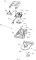
- the female buckle structures 90 namely, the first female buckle 102 and the second female buckle 202, each include the first housing 91, the second housing 92 and the locking part 93.
- the first housing 91 and the second housing 92 are docked to form installation space for installing the locking part 93.
- the second housing 92 is provided with a lock hole 921, and a shape of the lock hole 921 matches the shape of the lock tongue 81, so that the lock tongue 81 can be inserted.
- a magnet base 922 is provided in the second housing 92, and the position of the magnet base 922 corresponds to that of the lock hole 921.
- the magnet base 922 is provided with a magnet installation hole 9221, and a first magnetic member 94 is provided in the magnet installation hole 9221.
- a rectangular block-shaped magnet is selected as the first magnetic member 94, and the magnet installation hole 9221 is a rectangular groove.
- the position of the first magnetic member 94 corresponds to that of the lock hole 921, and the first magnetic member 94 attracts the second magnetic member 82. Therefore, when the lock tongue 81 faces toward the lock hole 921, the first magnetic member 94 and the second magnetic member 82 attract each other, so that the lock tongue 81 can be quickly inserted into the lock hole 921.
- a first side opening 9222 and a second side opening 9223 are provided in the side walls of the magnet base 922, and the first side opening 9222 and the second side opening 9223 are opposite each other and both communicate with the lock hole 921.
- the first side opening 9222 is used for moving the locking portion 931 to enter and exit the socket 811 of the lock tongue 81.
- the second side opening 9223 is used for moving the shoveling portion 933 to enter and exit an end of the lock tongue 81.
- the locking part 93 is movably located between the first housing 91 and the second housing 92, and has one end connected with the first drawstring 40 and the second drawstring 50 and another end that can be inserted into the socket 811 of the lock tongue 81 to be fitted with the lock tongue 81, so that the male buckle structure 80 and the female buckle structure 90 are locked together.
- the locking part 93 is pulled through the first drawstring 40 and the second drawstring 50, the locking part 93 can exit from the socket 811 of the lock tongue 81, so that the male buckle structure 80 and the female buckle structure 90 can be separated from each other.
- the locking part 93 includes an actuation portion 932, a locking portion 931 and a shoveling portion 933 that are integrally formed.
- the actuation portion 932 encircles the periphery of the magnet base 922, and can be used for restraining a displacement range of the locking part 93, so that the locking part 93 moves along a straight line.
- the actuation portion 932 is a rectangular frame-shaped structure.
- the locking portion 931 protrudes from an inner side of the actuation portion 932, and can be inserted into the socket 811 of the lock tongue 81 to be fitted with the lock tongue 81.
- a shape of the locking portion 931 matches that of the socket 811, and in this embodiment, the locking portion 931 is a rectangular block-shaped structure.
- a rectangular groove is disposed in the locking portion 931, and is embedded with a third magnetic member 95.
- the shoveling portion 933 protrudes from an inner side of the actuation portion 932, and is spaced apart from and disposed opposite the locking portion 931.
- the shoveling portion 933 is used for pushing out the lock tongue 81, so that the male buckle structure 80 and the female buckle structure 90 are separated from each other.
- the shoveling portion 933 directly faces the second side opening 9223 of the magnet base 922, and has an end that can be extended into the lock hole 921.
- the shoveling portion 933 can move toward the lock tongue 81 and act on the lock tongue 81.
- an end of the shoveling portion 933 is wedge-shaped.
- the shoveling portion 933 When the locking portion 93 is inserted into the socket 811, the shoveling portion 933 is spaced apart from the lock tongue 81. When the locking part 93 is pulled and moves in the direction of exiting the socket 811, the shoveling portion 933 moves towards the lock tongue 81 and gradually pushes out the lock tongue 81 in a direction opposite to the direction of inserting the lock tongue 81 into the lock hole 921, so that the male buckle structure 80 and the female buckle structure 90 are separated from each other.
- the shoveling portion 933 and the second side opening 9223 can also be configured to compel the locking part 93 to move in a straight line.
- the first magnetic member 94 repels the third magnetic member 95, and therefore, the locking part 93 can remain outside the lock hole 921 under a magnetic repulsion force of the first magnetic member 94 and the third magnetic member 95, to help insert the lock tongue 81 into the lock hole 921.
- the first magnetic member 94 attracts the second magnetic member 82, so that the lock tongue 81 is quickly inserted into the lock hole 921.
- the second magnetic member 82 in the lock tongue 81 and the third magnetic member 95 in the locking part 93 attract each other and actuate the locking part 93 to drive the locking part 93 to move toward the socket 811 of the lock tongue 81 and enter the socket 811, to be fitted with the lock tongue 81, so that the male buckle structure 80 remains on the female buckle structure 90 and cannot be removed.
- the first drawstring 40 and the second drawstring 50 are used for pulling the locking part 93, and in this embodiment, a wire rope is selected.
- the first drawstring 40 has one end connected with the unlocking operation member 31 and another end connected with the locking part 93 in the second female buckle 202, that is, specifically, a front end of the actuation portion 932 of the locking part 93.
- the second drawstring 50 has one end connected with the unlocking operation member 31 and another end connected with the locking part 93 in the second female buckle 202, that is, specifically, a front end of the actuation portion 932 of the locking part 93.
- the associated quick-release buckle device in this embodiment is formed.
- pressing portions 313 of the first unlocking operation member 311 and the second unlocking operation member 312 of the quick-release buckle 30 are pressed in opposite directions or the unlocking operation member 31 is rotated away from the buckle base 37, the first drawstring 40 and the second drawstring 50 are pulled to different degrees, at a certain moment, pulling displacement of the first drawstring 40 is greater than that of the second drawstring 50, and therefore, the locking part 93 in the first connection buckle 10 first completely exits from the socket 811 of the lock tongue 81 to unlock the first connection buckle 10; and as the first drawstring 40 and the second drawstring 50 continuously move, the locking part 93 in the second connection buckle 20 can also completely exit from the socket 811 to unlock the second connection buckle 20, thereby achieving an effect of unlocking the first connection buckle 10 and the second connection buckle 20 in sequence by pressing the first unlocking operation member 311 and the second unlocking operation member 312 in the opposite directions or rotating the unlocking operation member 31.
- the first connection buckle 10 and the second connection buckle 20 in this embodiment have the same structure and principle, but have slightly different external shapes and sizes.
- the first male buckle 101 and the second male buckle 201 are collectively referred to as the male buckle structures 80
- the first female buckle 102 and the second female buckle 202 are collectively referred to as the female buckle structures 90.
- the first male buckle 101 and the second male buckle 201 each are provided with a lock tongue 81.
- the lock tongue 81 protrudes from a joint surface on which the male buckle structure 80 is engaged with the female buckle structure 90.
- a shape of the lock tongue 81 is not limited, and in this embodiment, a cylindrical lock tongue 81 is disposed.
- a socket 811 is provided in the lock tongue 81, and the locking part 93 of the female buckle structure 90 can be inserted into the socket 811 to fit the male buckle structure 80 with the female buckle structure 90.
- the socket 811 is located at the side surface of the lock tongue 81, and therefore, an opening direction of the socket 811 is perpendicular to the direction in which the lock tongue 81 is inserted into the female buckle structure 90.
- the shape of the socket 811 can be set according to needs, and in this embodiment, the socket 811 is an annular groove.
- a second magnetic member 82 is provided in the lock tongue 81.
- a circular block-shaped magnet is selected as the second magnetic member 82.
- the female buckle structures 90 namely, the first female buckle 102 and the second female buckle 202, each include the first housing 91, the second housing 92 and the locking part 93.
- the first housing 91 and the second housing 92 are docked to form installation space for installing the locking part 93.
- the second housing 92 is provided with a lock hole 921, and a shape of the lock hole 921 matches the shape of the lock tongue 81, so that the lock tongue 81 can be inserted.
- a magnet base 922 is provided in the second housing 92, and the position of the magnet base 922 corresponds to that of the lock hole 921.
- the magnet base 922 is provided with a magnet installation hole 9221, and a first magnetic member 94 is provided in the magnet installation hole 9221.
- a rectangular block-shaped magnet is selected as the first magnetic member 94, and the magnet installation hole 9221 is a rectangular groove.
- the position of the first magnetic member 94 corresponds to that of the lock hole 921, and the first magnetic member 94 attracts the second magnetic member 82. Therefore, when the lock tongue 81 faces toward the lock hole 921, the first magnetic member 94 and the second magnetic member 82 attract each other, so that the lock tongue 81 can be quickly inserted into the lock hole 921.
- a first side opening 9222 and a second side opening 9223 are provided in the side walls of the magnet base 922, and the first side opening 9222 and the second side opening 9223 are opposite each other and both communicate with the lock hole 921.
- the first side opening 9222 is used for moving the locking portion 931 to enter and exit the socket 811 of the lock tongue 81.
- the second side opening 9223 is used for moving the shoveling portion 933 to enter and exit an end of the lock tongue 81.
- the locking part 93 is movably located between the first housing 91 and the second housing 92, and has one end connected with the first drawstring 40 and the second drawstring 50 and another end that can be inserted into the socket 811 of the lock tongue 81 to be fitted with the lock tongue 81, so that the male buckle structure 80 and the female buckle structure 90 are locked together.
- the locking part 93 is pulled through the first drawstring 40 and the second drawstring 50, the locking part 93 can exit from the socket 811 of the lock tongue 81, so that the male buckle structure 80 and the female buckle structure 90 can be separated from each other.
- the locking part 93 includes an actuation portion 932, a locking portion 931 and a shoveling portion 933 that can move relative to each other.
- the locking portion 931 can move relative to the actuation portion 932, and the shoveling portion 933 can move relative to the actuation portion 932.
- the actuation portion 932 encircles the periphery of the magnet base 922, and can be used for restraining a displacement range of the locking part 93, so that the locking part 93 moves along a straight line.
- the actuation portion 932 is a rectangular frame-shaped structure.
- the locking portion 931 is configured to be engaged with the lock tongue 81, is an independent structure relative to the actuation portion 932, is specifically spaced apart from the actuation portion 932, faces toward the actuation portion 932, and can move under the drive of the actuation portion 932.
- the locking portion 931 includes a main locking body and an upper convex column portion that are integrated.
- the main locking body is plate-shaped and has an arc-shaped end that can be inserted into the socket 811 of the lock tongue 81.
- the upper convex column portion protrudes from the main locking body, and is configured to interact with the actuation portion 932.
- the locking portion 931 and the actuation portion 932 are stacked and can be subjected to translation relative to each other.
- the upper convex column portion and the actuation portion 932 are spaced apart and disposed opposite each other.
- the actuation portion 932 can move toward the upper convex column portion and actuate the upper convex column portion under a pulling force of the corresponding first drawstring 40 or second drawstring 50, so that the main locking body can move away from the lock tongue 81 to detach the locking portion 931 from the lock tongue 81.
- a third magnetic member 95 is provided on the locking portion 931.
- the third magnetic member 95 can interact with the first magnetic member 94 and the second magnetic member 82 to implement functions such as locking and unlocking.
- the third magnetic member 95 and the second magnetic member 82 can repel and attract each other, which can be specifically set according to needs.
- the third magnetic member 9533 can be disposed in the following manner.
- the shoveling portion 933 is movably provided on an inner side of the actuation portion 932, and is spaced apart from and disposed opposite the locking portion 931.
- the shoveling portion 933 is used for pushing out the lock tongue 81, so that the male buckle structure 80 and the female buckle structure 90 are separated from each other.
- the shoveling portion 933 directly faces the second side opening 9223 of the magnet base 922, and has an end that can be extended into the lock hole 921.
- the shoveling portion 933 can move toward the lock tongue 81 and act on the lock tongue 81.
- an end of the shoveling portion 933 is wedge-shaped.
- a third elastic member 934 is provided between the shoveling portion 933 and the actuation portion 932.
- the third elastic member 934 is provided within the actuation portion 932.
- a restraint groove is provided in a portion, facing toward the locking portion 931, of the actuation portion 932, one end of the shoveling portion 933 is movably confined to the restraint groove and cannot escape from the restraint groove, and another end of the shoveling portion 933 is extended out of the restraint groove and forms a free end.
- the third elastic member 934 is provided in the restraint groove, and has one end abutting against the shoveling portion 933 and another end abutting against an inner wall of the restraint groove.
- the shoveling portion 933 only tends to drive the lock tongue 81 to detach from the lock hole 921, but cannot directly detach the lock tongue 81 from the lock hole 921.
- the actuation portion 932 can actuate the locking portion 931, to push the locking portion 931 away from the lock hole 921, so that the locking portion 931 detaches from the lock tongue 81.
- the shoveling portion 933 can drive the lock tongue 81 to detach from the lock hole 921, so that the male buckle structure 80 and the female buckle structure 90 are separated from each other.
- an abutting portion 935 is provided on an outer wall of the actuation portion 932, and a fourth elastic member 936 is provided between the abutting portion 935 and the female buckle.
- the fourth elastic member is compressed or stretched and therefore, has an ability of returning.
- the first drawstring 40 has one end connected with the unlocking operation member 31 and another end connected with the locking part 93 in the first female buckle 102, that is, specifically, a front end of the actuation portion 932 of the locking part 93.
- the second drawstring 50 has one end connected with the unlocking operation member 31 and another end connected with the locking part 93 in the second female buckle 202, that is, specifically, a front end of the actuation portion 932 of the locking part 93.
- the associated quick-release buckle device in this embodiment is formed.
- pressing portions 313 of the first unlocking operation member 311 and the second unlocking operation member 312 of the quick-release buckle 30 are pressed in opposite directions or the unlocking operation member 31 is rotated away from the buckle base 37, the first drawstring 40 and the second drawstring 50 are pulled to different degrees, at a certain moment, pulling displacement of the first drawstring 40 is greater than that of the second drawstring 50, and therefore, a movement degree of the actuation portion 932 in the first connection buckle 10 is greater than that of the actuation portion 932 in the second connection buckle 20, so that the locking portion 931 in the first connection buckle 10 is first actuated to detach from the lock tongue 81, thereby separating the first male buckle 101 from the first female buckle 102; and as the first drawstring 40 and the second drawstring 50 continuously move, the actuation portion 932 in the second connection buckle 20 can also actuate a corresponding locking portion 931, to detach the locking portion 931 from the lock tongue 81
- the quick-release buckles 30 in Embodiment 1 to Embodiment 4 can be used in combination with the first connection buckles 10 and the second connection buckles 20 in Embodiment 5 and Embodiment 6 respectively.
- Structures of the first connection buckle 10 and the second connection buckle 20 can be the same or different.
- the first connection buckle 10 can be designed with the structure in Embodiment 5 and the second connection buckle 20 is designed with the structure in Embodiment 6.
- the present invention further provides a bulletproof quick-release vest, including a front vest plate 61 and a back vest plate 62 and the foregoing associated quick-release buckle device.
- the front vest plate 61 and the back vest plate 62 can be connected with each other to be put on the upper body, and can be detached from each other to be easily taken off.
- one or two side shoulder portions of the front vest plate 61 and the back vest plate 62 are detachably connected through the second connection buckle 20.
- the two side shoulder portions of the front vest plate 61 and the back vest plate 62 are connected through two second connection buckles 20.
- a second female buckle 202 is fixed at each of the two shoulder portions of the front vest plate 61
- a second male buckle 201 is fixed at each of the two shoulder portions of the back vest plate 62
- the second female buckles 202 and the second male buckles 201 are fitted, so that the shoulder portions of the front vest plate 61 and the shoulder portions of the back vest plate 62 are connected together. Unlocking the second female buckle 202 and the second male buckle 201 can detach the shoulder portions of the front vest plate 61 from the shoulder portions of the back vest plate 62.
- One or two side waist portions of the front vest plate 61 and the back vest plate 62 are detachably connected through the first connection buckle 10.
- the first female buckles 102 are respectively fixed at the left waist portion and the right waist portion of the front vest plate 61
- the first male buckles 101 are respectively fixed at the left waist portion and the right waist portion of the back vest plate 62
- the first female buckles 102 and the first male buckles 101 are fitted, so that the waist portions of the front vest plate 61 and the waist portions of the back vest plate 62 are connected together. Unlocking the first female buckle 102 and the first male buckle 101 can detach the waist portions of the front vest plate 61 from the waist portions of the back vest plate 62.
- the quick-release buckle 30 is fixed on the front vest plate 61.
- a structure of the quick-release buckle 30 refer to Embodiment 1 to Embodiment 4.
- the first drawstring 40 and the second drawstring 50 are provided on the front vest plate 61.
- the first connection buckle 10 is first unlocked to first unlock the waist portions of the front vest plate 61 and the back vest plate 62, and then the second connection buckle 20 is unlocked to unlock the shoulder portions of the front vest plate 61 and the back vest plate 62, so that the front vest plate 61 and the back vest plate 62 are completely detached, thereby implementing quick release.
- the first connection buckle 10 is first unlocked to first unlock the waist portions of the front vest plate 61 and the back vest plate 62, and then the second connection buckle 20 is unlocked to unlock the shoulder portions of the front vest plate 61 and the back vest plate 62, so that the front vest plate 61 and the back vest plate 62 are completely detached, thereby implementing quick release.
- the waist portions of the front vest plate 61 and the back vest plate 62 are first unlocked and then the shoulder portions are unlocked, so that the second connection buckle 20 at the shoulder portion can be unlocked with assistance of self-weight of the bulletproof vest.
- the waist portions are unlocked after the shoulder portions, due to the self-weight of the bulletproof vest, the unlocked bulletproof vest falls down and gets stuck between legs.
- manual unlocking operation portions 96 are provided on the first connection buckle 10 and the second connection buckle 20.
- the manual unlocking operation portion 96 is operated, the corresponding first connection buckle 10 and second connection buckle 20 are unlocked.
- the manual unlocking operation portion 96 can be provided on the actuation portion 932, and is partly or completely exposed outside the female buckle, and the user can push or pull the manual unlocking operation portion 96 to move the actuation portion 932, to drive the locking portion 931 and the shoveling portion 933 to move, thereby implementing unlocking.
- a rope extended to the outside of the female buckle can be connected to the actuation portion 932, a pulling direction of the rope is consistent with that of the first drawstring 40 and the second drawstring 50, and the rope serves as the manual unlocking operation portion 96.
- the actuation portion 932 can move away from the lock hole 921 to drive the locking portion 931 and the shoveling portion 933 to move, thereby implementing unlocking.
Landscapes
- Engineering & Computer Science (AREA)
- General Engineering & Computer Science (AREA)
- Buckles (AREA)
- Professional, Industrial, Or Sporting Protective Garments (AREA)
Applications Claiming Priority (3)
| Application Number | Priority Date | Filing Date | Title |
|---|---|---|---|
| CN202210675780.4A CN115024562B (zh) | 2022-06-15 | 2022-06-15 | 联动快解扣装置及防弹快解马甲 |
| CN202310303927.1A CN116326891B (zh) | 2023-03-27 | 2023-03-27 | 快解扣 |
| PCT/CN2023/084545 WO2023241163A1 (fr) | 2022-06-15 | 2023-03-28 | Dispositif de boucle à déverrouillage rapide de liaison et gilet pare-balles à libération rapide |
Publications (2)
| Publication Number | Publication Date |
|---|---|
| EP4520217A1 true EP4520217A1 (fr) | 2025-03-12 |
| EP4520217A4 EP4520217A4 (fr) | 2026-01-07 |
Family
ID=89192154
Family Applications (1)
| Application Number | Title | Priority Date | Filing Date |
|---|---|---|---|
| EP23822734.2A Pending EP4520217A4 (fr) | 2022-06-15 | 2023-03-28 | Dispositif de boucle à déverrouillage rapide de liaison et gilet pare-balles à libération rapide |
Country Status (6)
| Country | Link |
|---|---|
| US (1) | US20250082073A1 (fr) |
| EP (1) | EP4520217A4 (fr) |
| JP (1) | JP2025524302A (fr) |
| KR (2) | KR20260046519A (fr) |
| TW (1) | TWI869887B (fr) |
| WO (1) | WO2023241163A1 (fr) |
Family Cites Families (15)
| Publication number | Priority date | Publication date | Assignee | Title |
|---|---|---|---|---|
| US8196273B2 (en) * | 2009-11-03 | 2012-06-12 | National Molding Llc | Quick release buckle assembly |
| CA2939765C (fr) * | 2013-09-16 | 2018-11-06 | Mku Pvt Ltd | Gilet se retirant rapidement |
| CN204757817U (zh) * | 2015-07-03 | 2015-11-11 | 北京润泽金松科技发展有限责任公司 | 快脱式防弹背心 |
| CN205642155U (zh) * | 2016-05-05 | 2016-10-12 | 广州市康珀宜凯贸易有限公司 | 一种快拆扣具及采用该快拆扣具的防弹服 |
| CN207351294U (zh) * | 2017-08-16 | 2018-05-11 | 北京鑫源荣海装备科技有限公司 | 一种快解式防弹背心 |
| KR101892018B1 (ko) * | 2018-04-13 | 2018-09-28 | 주식회사 산청 | 방탄조끼 |
| CN210773680U (zh) * | 2019-06-21 | 2020-06-16 | 江苏安华警用装备制造有限公司 | 一种快拆式防弹防刺服 |
| CN211012667U (zh) * | 2019-08-01 | 2020-07-14 | 广州市康珀宜凯贸易有限公司 | 一种快拆装模组化防弹服 |
| CN211178142U (zh) * | 2019-11-15 | 2020-08-04 | 深圳市鑫创达安全设备制造有限公司 | 一种便捷式防弹衣 |
| TWM591777U (zh) * | 2019-12-31 | 2020-03-11 | 國防部軍備局生產製造中心第205廠 | 快速拆卸背心 |
| JP7491181B2 (ja) | 2020-10-20 | 2024-05-28 | 王子ホールディングス株式会社 | 感熱記録体 |
| CN114027582B (zh) * | 2021-04-18 | 2023-09-15 | 联扬塑胶(深圳)有限公司 | 磁性扣具 |
| CN215337977U (zh) * | 2021-05-17 | 2021-12-28 | 北京安龙科技集团有限公司 | 快拆式防弹衣 |
| KR102296586B1 (ko) * | 2021-05-20 | 2021-09-01 | 우일무역(주) | 개량 원터치 버클 |
| CN115024562B (zh) * | 2022-06-15 | 2025-06-03 | 联扬塑胶(深圳)有限公司 | 联动快解扣装置及防弹快解马甲 |
-
2023
- 2023-03-28 KR KR1020267008802A patent/KR20260046519A/ko active Pending
- 2023-03-28 EP EP23822734.2A patent/EP4520217A4/fr active Pending
- 2023-03-28 KR KR1020247039585A patent/KR102951121B1/ko active Active
- 2023-03-28 WO PCT/CN2023/084545 patent/WO2023241163A1/fr not_active Ceased
- 2023-03-28 JP JP2024569624A patent/JP2025524302A/ja active Pending
- 2023-06-15 TW TW112122495A patent/TWI869887B/zh active
-
2024
- 2024-11-24 US US18/957,763 patent/US20250082073A1/en active Pending
Also Published As
| Publication number | Publication date |
|---|---|
| KR20250002682A (ko) | 2025-01-07 |
| US20250082073A1 (en) | 2025-03-13 |
| EP4520217A4 (fr) | 2026-01-07 |
| TWI869887B (zh) | 2025-01-11 |
| WO2023241163A1 (fr) | 2023-12-21 |
| KR20260046519A (ko) | 2026-04-07 |
| TW202400039A (zh) | 2024-01-01 |
| JP2025524302A (ja) | 2025-07-29 |
| KR102951121B1 (ko) | 2026-04-10 |
Similar Documents
| Publication | Publication Date | Title |
|---|---|---|
| KR102208912B1 (ko) | 자기 버클링 어셈블리 | |
| US8539652B2 (en) | Latching fastener with locking feature | |
| US10202790B2 (en) | Closure device for connecting two parts | |
| US20130000084A1 (en) | Self-actuating magnetic locking system | |
| CN211632015U (zh) | 磁性扣具 | |
| AU2024216384A1 (en) | Child safety seat and detachable side impact protection block | |
| CN108669712A (zh) | 一种自动插合分离锁扣 | |
| EP4520217A1 (fr) | Dispositif de boucle à déverrouillage rapide de liaison et gilet pare-balles à libération rapide | |
| CN114027592B (zh) | 拉动解锁的扣具装置 | |
| WO2020154132A1 (fr) | Techniques de récepteur de bouton à pression | |
| EP3867165B1 (fr) | Système de raccordement de récipient | |
| CN115024562B (zh) | 联动快解扣装置及防弹快解马甲 | |
| KR101878701B1 (ko) | 버클 조립체 | |
| CN107125855A (zh) | 安全扣具、安全扣具组、安全防护装置及安全服衣襟 | |
| RU2023631C1 (ru) | Центральный замок подвесной системы | |
| CN213621201U (zh) | 一种置物袋锁扣及包含其的助行车置物袋 | |
| US10932530B2 (en) | Container connection system | |
| TWM673731U (zh) | 快拆結構 | |
| HK40089357A (en) | Child safety seat and detachable side collision protective block |
Legal Events
| Date | Code | Title | Description |
|---|---|---|---|
| STAA | Information on the status of an ep patent application or granted ep patent |
Free format text: STATUS: THE INTERNATIONAL PUBLICATION HAS BEEN MADE |
|
| PUAI | Public reference made under article 153(3) epc to a published international application that has entered the european phase |
Free format text: ORIGINAL CODE: 0009012 |
|
| STAA | Information on the status of an ep patent application or granted ep patent |
Free format text: STATUS: REQUEST FOR EXAMINATION WAS MADE |
|
| 17P | Request for examination filed |
Effective date: 20241202 |
|
| AK | Designated contracting states |
Kind code of ref document: A1 Designated state(s): AL AT BE BG CH CY CZ DE DK EE ES FI FR GB GR HR HU IE IS IT LI LT LU LV MC ME MK MT NL NO PL PT RO RS SE SI SK SM TR |
|
| RIC1 | Information provided on ipc code assigned before grant |
Ipc: A44B 11/26 20060101AFI20250804BHEP Ipc: F41H 1/02 20060101ALI20250804BHEP |
|
| DAV | Request for validation of the european patent (deleted) | ||
| DAX | Request for extension of the european patent (deleted) | ||
| STAA | Information on the status of an ep patent application or granted ep patent |
Free format text: STATUS: EXAMINATION IS IN PROGRESS |
|
| A4 | Supplementary search report drawn up and despatched |
Effective date: 20251208 |
|
| RIC1 | Information provided on ipc code assigned before grant |
Ipc: A44B 11/26 20060101AFI20251202BHEP Ipc: F41H 1/02 20060101ALI20251202BHEP |
|
| 17Q | First examination report despatched |
Effective date: 20251219 |