EP4520222A1 - Applikatorkopf zum auftragen eines kosmetischen produkts - Google Patents
Applikatorkopf zum auftragen eines kosmetischen produkts Download PDFInfo
- Publication number
- EP4520222A1 EP4520222A1 EP24190381.4A EP24190381A EP4520222A1 EP 4520222 A1 EP4520222 A1 EP 4520222A1 EP 24190381 A EP24190381 A EP 24190381A EP 4520222 A1 EP4520222 A1 EP 4520222A1
- Authority
- EP
- European Patent Office
- Prior art keywords
- applicator
- thermal member
- applicator head
- distal
- thermal
- Prior art date
- Legal status (The legal status is an assumption and is not a legal conclusion. Google has not performed a legal analysis and makes no representation as to the accuracy of the status listed.)
- Pending
Links
Images





Classifications
-
- A—HUMAN NECESSITIES
- A45—HAND OR TRAVELLING ARTICLES
- A45D—HAIRDRESSING OR SHAVING EQUIPMENT; EQUIPMENT FOR COSMETICS OR COSMETIC TREATMENTS, e.g. FOR MANICURING OR PEDICURING
- A45D40/00—Casings or accessories specially adapted for storing or handling solid or pasty toiletry or cosmetic substances, e.g. shaving soaps or lipsticks
- A45D40/26—Appliances specially adapted for applying pasty paint, e.g. using roller, using a ball
-
- A—HUMAN NECESSITIES
- A45—HAND OR TRAVELLING ARTICLES
- A45D—HAIRDRESSING OR SHAVING EQUIPMENT; EQUIPMENT FOR COSMETICS OR COSMETIC TREATMENTS, e.g. FOR MANICURING OR PEDICURING
- A45D34/00—Containers or accessories specially adapted for handling liquid toiletry or cosmetic substances, e.g. perfumes
- A45D34/04—Appliances specially adapted for applying liquid, e.g. using roller or ball
- A45D34/042—Appliances specially adapted for applying liquid, e.g. using roller or ball using a brush or the like
- A45D34/045—Appliances specially adapted for applying liquid, e.g. using roller or ball using a brush or the like connected to the cap of the container
-
- A—HUMAN NECESSITIES
- A45—HAND OR TRAVELLING ARTICLES
- A45D—HAIRDRESSING OR SHAVING EQUIPMENT; EQUIPMENT FOR COSMETICS OR COSMETIC TREATMENTS, e.g. FOR MANICURING OR PEDICURING
- A45D33/00—Containers or accessories specially adapted for handling powdery toiletry or cosmetic substances
-
- A—HUMAN NECESSITIES
- A45—HAND OR TRAVELLING ARTICLES
- A45D—HAIRDRESSING OR SHAVING EQUIPMENT; EQUIPMENT FOR COSMETICS OR COSMETIC TREATMENTS, e.g. FOR MANICURING OR PEDICURING
- A45D40/00—Casings or accessories specially adapted for storing or handling solid or pasty toiletry or cosmetic substances, e.g. shaving soaps or lipsticks
- A45D40/26—Appliances specially adapted for applying pasty paint, e.g. using roller, using a ball
- A45D40/262—Appliances specially adapted for applying pasty paint, e.g. using roller, using a ball using a brush or the like
- A45D40/265—Appliances specially adapted for applying pasty paint, e.g. using roller, using a ball using a brush or the like connected to the cap of the container
-
- A—HUMAN NECESSITIES
- A45—HAND OR TRAVELLING ARTICLES
- A45D—HAIRDRESSING OR SHAVING EQUIPMENT; EQUIPMENT FOR COSMETICS OR COSMETIC TREATMENTS, e.g. FOR MANICURING OR PEDICURING
- A45D2200/00—Details not otherwise provided for in A45D
- A45D2200/15—Temperature
-
- A—HUMAN NECESSITIES
- A45—HAND OR TRAVELLING ARTICLES
- A45D—HAIRDRESSING OR SHAVING EQUIPMENT; EQUIPMENT FOR COSMETICS OR COSMETIC TREATMENTS, e.g. FOR MANICURING OR PEDICURING
- A45D2200/00—Details not otherwise provided for in A45D
- A45D2200/15—Temperature
- A45D2200/152—Walls with thermally insulating properties, i.e. preventing the exposure of cosmetics to the exterior temperature
-
- A—HUMAN NECESSITIES
- A45—HAND OR TRAVELLING ARTICLES
- A45D—HAIRDRESSING OR SHAVING EQUIPMENT; EQUIPMENT FOR COSMETICS OR COSMETIC TREATMENTS, e.g. FOR MANICURING OR PEDICURING
- A45D2200/00—Details not otherwise provided for in A45D
- A45D2200/15—Temperature
- A45D2200/155—Heating or cooling means, i.e. for storing or applying cosmetic products at a predetermined temperature
-
- A—HUMAN NECESSITIES
- A45—HAND OR TRAVELLING ARTICLES
- A45D—HAIRDRESSING OR SHAVING EQUIPMENT; EQUIPMENT FOR COSMETICS OR COSMETIC TREATMENTS, e.g. FOR MANICURING OR PEDICURING
- A45D2200/00—Details not otherwise provided for in A45D
- A45D2200/15—Temperature
- A45D2200/155—Heating or cooling means, i.e. for storing or applying cosmetic products at a predetermined temperature
- A45D2200/157—Heating means for mascara applicators
Definitions
- Embodiments of the present disclosure generally relate to an applicator head for applying a product including a cosmetic, care or pharmaceutical product onto human skin or keratinous fibers, such as, for example, hair, eyebrows, nails and/or eyelashes.
- the product includes viscous liquid, semisolid or powder product.
- Cosmetic applicators such as dip or wand applicators are known in the cosmetic industry. Cosmetic packages often include such applicators for dispensing a particular cosmetic contained in the package reservoir.
- the cosmetic applicator generally includes a stem with a cap at one end and an applicator head in the form of a brush, spatula or other applicator structure suitable for applying a cosmetic or a care product including viscous cosmetics, mascara, eye liner, lip gloss, hair color, wound care, skin care, under eye cosmetics, pharmaceutical and like products.
- One such applicator is disclosed in U.S. Pat. No. 10,888,145 B2 for applying a cosmetic product to a user's skin.
- the applicator head comprises a first applicator member and a second applicator member.
- the first applicator member is cylindrical in shape and has a cavity extending throughout a length of the first applicator member.
- the non-thermal member is received within the cavity of the first applicator member.
- U.S. Pat. No. 7,481,591 discloses an applicator comprising a rod and an application surface formed of a plurality of cones. These cones have a certain elasticity and movability and can therefore massage the cosmetic product, which is stored between them into wrinkles and uneven areas of the skin of a user.
- U.S. Application No. 20,200,329,846 A1 discloses an applicator head comprising a first applying member, a second applying member and a locking part.
- the first applying member at least partially encompasses the second applying member and wherein at least a portion of the second applying member is made of a heat transfer material to transfer the heat or cold on contact with the keratinous substrate of a user.
- an applicator head configured to apply a cosmetic product and capable of providing cooling or heating sensation on a user's skin.
- the technical task underlying the present invention is to provide an applicator head capable of substantially obviating at least some of the aforementioned drawbacks.
- the applicator head has a reservoir which insulates at least one portion of the thermal storage material, thereby preventing the possibility of 360 degrees contact of an outer surface of the heat transfer material with the skin. Limiting the outer surface of the thermal storage material which makes contact with the skin increases the time of heating or cooling sensation on the skin.
- an applicator head used to apply a product including a cosmetic or a care product.
- the applicator head elongates along a longitudinal axis.
- the applicator head comprises a thermal member and a secondo or non-thermal member.
- the thermal member is made of a thermal storage material such as metal, ceramic, metal alloy, or a stone.
- the thermal member may be used for massaging the user's skin.
- the thermal member defines at least a sidewall of the applicator head and the non-thermal member defines at least a distal surface of the applicator head.
- the thermal member has a cavity that extends through at least a portion of a length of the thermal member.
- the cosmetic or care product includes viscous cosmetics, mascara, eyebrow powder, lip gloss, hair color, skin care, under eye cosmetics, pharmaceutical and like products.
- the applicator head is intended to be retained at a distal end of the stem.
- the thermal member comprises a proximal portion and a distal portion.
- the proximal portion is formed as a shank portion that is configured to be received within a cavity of a stem.
- the distal portion of the thermal member is configured to be located outside the stem and is formed as a first applicator portion that is accessible to the user for application purpose.
- the first applicator portion of the thermal member includes at least two main faces i.e. a front face, and a rear face. Further, the first applicator portion also comprises a right-side face, and a left side face.
- the front face includes a proximal surface and a distal surface. The distal surface extends from a distal end of thermal member and/the applicator head towards a front side of the applicator head.
- the distal surface is an inclined surface that extends along at least 50% of a length of the front face.
- the distal surface of the front face of thermal member is concave and the proximal surface of the front face is convex.
- the rear face of the first applicator portion of the thermal member provides a large convex surface that can be used for massaging. More particularly, the rear face of the first applicator portion is curved along the longitudinal axis of the applicator head as well as in a direction orthogonal to the longitudinal axis of the applicator head.
- the distal end of the thermal member is slightly off-centred with respect to the longitudinal axis towards the rear face of the first applicator portion.
- the distal end of the thermal member and/or the applicator head may or may not be located at the longitudinal axis.
- the distal surface of the first applicator portion has a drop shape with an apex forming at the distal end thereof.
- the distal surface of the first applicator portion may have any other desirable shape.
- an opening for the cavity is defined on the distal surface of the first applicator portion of the thermal member.
- the distal surface is curved and inclined, the opening is also extends oblique with respect to the central longitudinal axis of the applicator head.
- the opening may have any desirable shape including spatulate, obovate, elliptic, oblong, deltoid, a cross, rectangular, square, triangular, heart or an irregular shape for example.
- the first applicator portion of the thermal member may include at least one application element adapted to convey and apply cosmetic product.
- the application element may be tine, projection, bristle, flocking, rib, groove, disc, slit, cut, hole, dimple, foam or other surface features or surface treatments (e.g., abrading) that are suitable for combing and/or loading, transporting and applying cosmetic product.
- the non-thermal member is an insulator fabricated from a group of materials consisting of plastic, wood, rubber, sintered or porous material and/or combinations thereof.
- the non-thermal member comprises an elongated rod portion and a second applicator portion.
- the second applicator portion projects or extends out from the opening of the cavity at the concave distal surface of the first applicator portion of the thermal member, and a major portion of the elongated rod portion is housed within the cavity of the thermal member.
- the second applicator portion is connected (e.g. fixedly) to, or molded integrally with the elongated rod portion.
- the elongated rod portion of the non-thermal member has a length greater than the length of the cavity of the thermal member and therefore, the elongated rod portion extends out from a proximal end of the cavity of the thermal member.
- the second applicator portion extends along a plane.
- the plane is a curved plane.
- the plane of the second applicator portion enables it to closely match the plane of the distal surface of the first applicator portion and provides a better fit once assembled.
- the second applicator portion is provided an upper surface and a bottom surface, and wherein the upper surface is a continuously concavely curved surface and the bottom surface is a convexly curved surface.
- the bottom surface is designed and dimensioned to closely contact the distal surface of the first applicator portion of the thermal member.
- the second applicator portion is drop-shaped similar to the size of the distal surface.
- the second applicator portion is shaped and dimensioned to fit over and cover the distal surface of the first applicator portion.
- the elongated rod portion extends downwards from the bottom surface.
- the upper surface of the second applicator portion of the non-thermal member is configured to apply/spread the product on the user's skin.
- the wiper cleans the applicator head in a manner such that an optimal amount of product is retained on the upper surface of the second applicator portion so that a user may use the second applicator portion of the non-thermal member to transfer product to a human keratinous surface.
- the upper surface of the second applicator portion creates a volume reservoir.
- This volume reservoir serves as a reservoir for the cosmetic product.
- a significant quantity of the cosmetic product may be accommodated in said volume reservoir which is available to be applied to the user's skin or keratinous substrate.
- At least a part of the upper surface of the second applicator portion comprises flocking.
- the upper surface of the second applicator portion may not be flocked.
- the concavely curved upper surface of the second applicator portion may comprise projections, ribs, grooves, other surface features or surface treatments (e.g., abrading) that are suitable for loading, transporting and applying cosmetic product.
- the elongated rod portion of the non-thermal member can be retained within the cavity of the thermal member, by locking means known in art such as a j-lock, a threaded engagement, an interference engagement, magnetic engagement or the like.
- the thermal member and the non-thermal member are secured to each other by snap-fitment.
- the thermal member may include an annular projection on its inner surface and the elongated rod portion of the non-thermal member may include an annular recess and an annular flange adjacent to said annular recess.
- the elongated rod portion of the non-thermal member is inserted into the cavity of the thermal member through the concave distal portion of the thermal member, the annular projection of the thermal member is snap fitted into the corresponding annular recess of the non-thermal member, and thus the further insertion of the non-thermal member with respect to the thermal member is limited. Further, the annular flange of the non-thermal member is locked against the annular projection making removal of the non-thermal member difficult towards the opening.
- the annular projection may be on the non-thermal member in which case, the annular recess is on the thermal member.
- the non-thermal member is so oriented that an apex of the non-thermal member is always in line with an apex of the thermal member.
- the elongated rod portion has a rectangular portion located close to the second applicator portion that corresponds to a rectangular portion of the cavity near the opening which helps to orient and prevent the rotation of the second applicator portion with respect to the thermal member.
- a cosmetic package associated with the applicator head and comprises a receptacle for holding a product and an applicator assembly.
- the applicator assembly comprises the applicator head, a stem, and a cap.
- the cap of the applicator assembly has threads that can be screwed onto threads, formed on a neck of the receptacle.
- the applicator head is retained at a distal end of the stem for applying the product; and the cap at a proximal end of the stem.
- distal and proximal are supposed to mean that the distal side/end is the side/end facing towards the inside of the storage receptacle, whereas the proximal side/end is the side/end facing towards the opening of the receptacle.
- the distal end of the stem includes an interior longitudinal cavity for receiving and retaining the applicator head.
- a wiper Inserted in the neck of the receptacle is a wiper for wiping off excess product from the applicator assembly.
- the applicator head of the applicator assembly may be used to apply the product including a cosmetic or care product.
- the cosmetic or care product includes viscous cosmetics, mascara, eyebrow powder, lip gloss, hair color, skin care, under eye cosmetics, pharmaceutical and like products.
- the applicator head and the stem may be fit together by friction fit, snap fit, by gluing, crimping, magnetic engagement and the like.
- the applicator head and the stem are fitted together by snap fitment.
- the shank portion of the thermal member includes at least one annular bead and the inner surface of the stem cavity includes a corresponding annular recess. When the shank portion of the applicator head is inserted into the interior longitudinal cavity of the stem, the at least one annular bead is snap-fitted into the corresponding annular recess.
- An applicator head is provided according to a second embodiment of the present disclosure,
- the applicator head of the second embodiment is similar to the applicator head in the first embodiment, with the exception that the shapes of the thermal member and non-thermal member differ between these two embodiments.
- a thermal member of the second embodiment forms part of a sidewall of the applicator head, while the non-thermal member of the second embodiment contributes to a distal surface of the applicator head.
- a distal portion the thermal member is a first applicator portion which is located outside the stem for user application. Further, the first applicator portion of the thermal member consists of a front face, rear face, right-side face, and left-side face.
- a wiper 60 for wiping off excess product from the applicator assembly 30.
- the applicator head 10 elongates along a longitudinal axis X.
- the applicator head 10 preferably comprises a thermal member 2 and a second member 12.
- the thermal member 2 defines at least a portion of a sidewall of the applicator head 10 and the second member 12 defines a portion of a distal surface of the applicator head 10.
- the thermal member 2 is configured to receive and retain at least a portion of the second member 12.
- the thermal member 2 is preferably made of a thermal storage material such as metal, ceramic, metal alloy, or a stone. Therefore, the thermal member 2 may be used for massaging the user's skin.
- a diameter of the shank portion 3 is less than a maximum diameter of the distal portion 2b of the thermal member 2.
- the upper surface 14a of the second applicator portion 14 of the non-thermal member 12 is preferably configured to apply/spread the product on the user's skin.
- the wiper 60 cleans the applicator head 10 in a manner such that an optimal amount of product is retained on the upper surface 14a of the second applicator portion 14 so that a user may use the second applicator portion 14 of the non-thermal member 12 to transfer product to a human keratinous surface.
- the upper surface 14a of the second applicator portion 14 creates a volume reservoir. This volume reservoir serves as a reservoir for the cosmetic product. A significant quantity of the cosmetic product may be accommodated in said volume reservoir which is available to be applied to the user's skin or keratinous substrate.
- the annular projection 15 may be on the non-thermal member 12 in which case, the annular recess 16 is on the thermal member 2.
- the applicator head 10 and the stem 40 may be fit together by friction fit, snap fit, by gluing, crimping, magnetic engagement and the like.
- the application head 10 and the stem 40 are fitted together by snap fitment.
- the shank portion 2a of the thermal member 2 includes at least one annular bead 2c and the inner surface of the stem cavity 42 includes corresponding annular recess 43.
- the shank portion 2a of the applicator head 10 is inserted into the interior longitudinal cavity 42 of the stem 40, the at least one annular bead 2c is snap-fitted into a corresponding annular recess 43.
- the non-thermal member 12 preferably is a non-thermal material and preferably it is fabricated from a material selected from a group consisting of plastic, wood, rubber, sintered or porous material and/or combinations thereof and it is preferably a polymer and mor preferably a thermoplastic polymer.
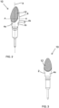
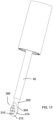
- FIG. 10 illustrates a longitudinal sectional view of a cosmetic package 1000 including an applicator head 200 according to a second embodiment of the present disclosure.
- the applicator head 200 is similar to the applicator head 10 in the first embodiment, preferably with the exception that the shapes of the thermal member and non-thermal member differ between these two embodiments.
- a thermal member 202 forms part of a sidewall of the applicator head 200, while the non-thermal member 212 contributes to a distal surface of the applicator head 200.
- a proximal portion of the thermal member 202 is a shank portion 203 which is configured to be fitted into a cavity 42 of the stem 40.
- a distal portion the thermal member 202 is a first applicator portion 204 which is located outside the stem for user application.
- the first applicator portion 204 of the thermal member 202 consists of a front face 204a, rear face 204b, right-side face 204c, and left-side face 204d as seen in FIG. 13 and FIG. 15 .
- the front face 204a includes a proximal surface 205a, and a distal surface 205b.
- the proximal surface 205a is a convex surface.
- the distal surface 205b is a slanted and flat surface that extends along at least 40% of a length of the first applicator portion 204.
- the rear face 204b is lip-shaped along the length direction of the applicator head 200. More particularly, the rear face 204b includes a proximal convex portion 207 followed by a central recessed area 208 and a distal convex portion 209 as seen in FIG. 15 .
- the distal surface 205b of the first applicator portion 204 has a drop shape with an apex at the distal end 211 as seen in FIG. 11 .
- a cavity 206 runs through at least a portion of the thermal member 202, with at least a portion of the non-thermal member 212 fitting inside it.
- the non-thermal member 212 consists of an elongated rod portion 213 and a second applicator portion 214. When the non-thermal member 212 is placed inside the cavity 206 of the thermal member 202, the second applicator portion 214 extends out from the opening 207 of the cavity 206 on the distal surface 205b of the first applicator portion 204.
- the second applicator portion 214 has preferably an upper surface 214a and a bottom surface 214b. Unlike the first embodiment, the second applicator portion 214 in the second embodiment is a flat surface instead of a concave surface. Both the upper surface 214a and the bottom surface 214b of the second applicator portion 214 are flat surfaces.
- FIG.16 illustrates a longitudinal sectional view of a cosmetic package 2000 including an applicator head 300 according to a third embodiment of the present disclosure.
- the applicator head 300 is preferably rounded and oval-shaped.
- the applicator head 300 includes one or more through cavities 315 as seen in FIG. 17 . These one or more through cavities serve to optimize product application, control product release, enhance flexibility, and contribute to the overall aesthetics.
- the applicator head 300 includes a thermal member 302, which forms part of a sidewall of the applicator head 300, and a non-thermal member 312 which contributes to a distal surface of the applicator head 300.
- a cavity 306 runs through at least a portion of the thermal member 302, with at least a portion of the non-thermal member 312 fitting inside it.
- An opening 307 for the cavity 306 is situated on the distal surface 305 of the first applicator portion 304.
- the non-thermal member 312 consists of an elongated rod portion 313 and a second applicator portion 314. When the non-thermal member 312 is placed inside the cavity 306 of the thermal member 302, the second applicator portion 314 extends out from the opening 307 of the cavity 306 on the distal surface 305 of the first applicator portion 304.
- the second applicator portion 314 has a convex body that aligns with the distal surface 305 of the first applicator portion 304 to form an oval and rounded applicator head 300.
- the second applicator portion 314 preferably includes one or more through cavities 315 which extend transverse to a length direction of the applicator head 300, refer FIGS. 18-20 .
- the one or more cavities 315 may differ in their sizes or shapes. However, it is within the scope of the current disclosure that the one or more cavities 315 may have same sizes or shapes.
- At least a portion of the second applicator portions 14, 214, 314 of the applicator heads 10, 200, 300 of the present disclosure may or may not include flocking.
Landscapes
- Coating Apparatus (AREA)
Applications Claiming Priority (1)
| Application Number | Priority Date | Filing Date | Title |
|---|---|---|---|
| IT102023000018615A IT202300018615A1 (it) | 2023-09-11 | 2023-09-11 | Testa di applicatore per applicare un prodotto cosmetico |
Publications (1)
| Publication Number | Publication Date |
|---|---|
| EP4520222A1 true EP4520222A1 (de) | 2025-03-12 |
Family
ID=88778518
Family Applications (1)
| Application Number | Title | Priority Date | Filing Date |
|---|---|---|---|
| EP24190381.4A Pending EP4520222A1 (de) | 2023-09-11 | 2024-07-23 | Applikatorkopf zum auftragen eines kosmetischen produkts |
Country Status (3)
| Country | Link |
|---|---|
| US (1) | US20250082088A1 (de) |
| EP (1) | EP4520222A1 (de) |
| IT (1) | IT202300018615A1 (de) |
Families Citing this family (1)
| Publication number | Priority date | Publication date | Assignee | Title |
|---|---|---|---|---|
| CN120859266A (zh) * | 2024-04-30 | 2025-10-31 | 洽兴包装工业(中国)有限公司 | 分体式涂抹器以及包含该涂抹器的包装容器 |
Citations (5)
| Publication number | Priority date | Publication date | Assignee | Title |
|---|---|---|---|---|
| US7481591B2 (en) | 2005-08-11 | 2009-01-27 | Geka Brush Gmbh | Application for cosmetic product |
| US20200329846A1 (en) | 2019-04-20 | 2020-10-22 | Toly Management Ltd. | Cosmetic applicator with heat transfer component |
| US10888145B2 (en) | 2017-04-04 | 2021-01-12 | Toly Management Ltd. | Cosmetic applicator |
| US11412832B2 (en) * | 2020-02-12 | 2022-08-16 | Toly Management Ltd. | Cosmetic applicator with rotatable application surface |
| US11653739B1 (en) * | 2022-01-31 | 2023-05-23 | APR Beauty Group, Inc. | Applicator head for a fluid product |
Family Cites Families (2)
| Publication number | Priority date | Publication date | Assignee | Title |
|---|---|---|---|---|
| FR3136639B1 (fr) * | 2022-06-15 | 2026-02-06 | Oreal | Tête d'applicateur, dispositif applicateur et procédé cosmétique |
| US20240358141A1 (en) * | 2023-04-27 | 2024-10-31 | Elc Management Llc | Partially treated cosmetic product applicator |
-
2023
- 2023-09-11 IT IT102023000018615A patent/IT202300018615A1/it unknown
-
2024
- 2024-07-23 EP EP24190381.4A patent/EP4520222A1/de active Pending
- 2024-09-09 US US18/828,608 patent/US20250082088A1/en active Pending
Patent Citations (5)
| Publication number | Priority date | Publication date | Assignee | Title |
|---|---|---|---|---|
| US7481591B2 (en) | 2005-08-11 | 2009-01-27 | Geka Brush Gmbh | Application for cosmetic product |
| US10888145B2 (en) | 2017-04-04 | 2021-01-12 | Toly Management Ltd. | Cosmetic applicator |
| US20200329846A1 (en) | 2019-04-20 | 2020-10-22 | Toly Management Ltd. | Cosmetic applicator with heat transfer component |
| US11412832B2 (en) * | 2020-02-12 | 2022-08-16 | Toly Management Ltd. | Cosmetic applicator with rotatable application surface |
| US11653739B1 (en) * | 2022-01-31 | 2023-05-23 | APR Beauty Group, Inc. | Applicator head for a fluid product |
Also Published As
| Publication number | Publication date |
|---|---|
| IT202300018615A1 (it) | 2025-03-11 |
| US20250082088A1 (en) | 2025-03-13 |
Similar Documents
| Publication | Publication Date | Title |
|---|---|---|
| US10888145B2 (en) | Cosmetic applicator | |
| CN220876187U (zh) | 涂抹化妆品的涂抹器头 | |
| KR101938505B1 (ko) | 2 개의 조립된 부분을 포함하는 도포기 부재 | |
| CA2760849C (en) | Compressible cosmetic applicator | |
| US20190125059A1 (en) | Cosmetic applicator | |
| US10172435B2 (en) | Cosmetic applicator | |
| US11882926B2 (en) | Adjustable applicator | |
| EP3462977B1 (de) | Kosmetischer applikator mit einer geformten und einer nichtgeformten bürste | |
| JP3782979B2 (ja) | 化粧品等のための包装および塗布装置 | |
| US20200329847A1 (en) | Cosmetic applicator with separate brush and molded applicator structures | |
| US11412832B2 (en) | Cosmetic applicator with rotatable application surface | |
| JP7181384B2 (ja) | 製品、特に化粧品を塗布するためのアプリケータ | |
| US12042035B2 (en) | Cosmetic applicator with heat transfer component | |
| US9516939B2 (en) | Cosmetic applicator | |
| EP4520222A1 (de) | Applikatorkopf zum auftragen eines kosmetischen produkts | |
| US11925250B2 (en) | Cosmetic applicator | |
| EP3197314B1 (de) | Applikator zum auftragen eines kosmetischen oder pflegenden produkts | |
| US12193554B2 (en) | Applicator head for applying a cosmetic product | |
| US11758997B1 (en) | Applicator head for applying a cosmetic product | |
| KR20210097605A (ko) | 페이스 어플리케이션 부재 및 펌프를 갖는 화장품 어플리케이터 | |
| US11684136B1 (en) | Cosmetic package and an applicator head for applying a fluid product | |
| JP2023531499A (ja) | 支持用アームによって支持された空洞を有する化粧品適用具 | |
| CN220545955U (zh) | 涂抹化妆品的涂抹器头 | |
| KR200492534Y1 (ko) | 마스카라 | |
| JP7148104B1 (ja) | 化粧料塗布具 |
Legal Events
| Date | Code | Title | Description |
|---|---|---|---|
| PUAI | Public reference made under article 153(3) epc to a published international application that has entered the european phase |
Free format text: ORIGINAL CODE: 0009012 |
|
| STAA | Information on the status of an ep patent application or granted ep patent |
Free format text: STATUS: THE APPLICATION HAS BEEN PUBLISHED |
|
| STAA | Information on the status of an ep patent application or granted ep patent |
Free format text: STATUS: REQUEST FOR EXAMINATION WAS MADE |
|
| AK | Designated contracting states |
Kind code of ref document: A1 Designated state(s): AL AT BE BG CH CY CZ DE DK EE ES FI FR GB GR HR HU IE IS IT LI LT LU LV MC ME MK MT NL NO PL PT RO RS SE SI SK SM TR |
|
| 17P | Request for examination filed |
Effective date: 20250228 |
|
| GRAP | Despatch of communication of intention to grant a patent |
Free format text: ORIGINAL CODE: EPIDOSNIGR1 |
|
| STAA | Information on the status of an ep patent application or granted ep patent |
Free format text: STATUS: GRANT OF PATENT IS INTENDED |
|
| RIC1 | Information provided on ipc code assigned before grant |
Ipc: A45D 40/26 20060101AFI20260227BHEP |