EP4520409A1 - Piscine à courant - Google Patents
Piscine à courant Download PDFInfo
- Publication number
- EP4520409A1 EP4520409A1 EP23195288.8A EP23195288A EP4520409A1 EP 4520409 A1 EP4520409 A1 EP 4520409A1 EP 23195288 A EP23195288 A EP 23195288A EP 4520409 A1 EP4520409 A1 EP 4520409A1
- Authority
- EP
- European Patent Office
- Prior art keywords
- reservoir
- swimming pool
- turbine
- liquid line
- section
- Prior art date
- Legal status (The legal status is an assumption and is not a legal conclusion. Google has not performed a legal analysis and makes no representation as to the accuracy of the status listed.)
- Granted
Links
Images

Classifications
-
- A—HUMAN NECESSITIES
- A63—SPORTS; GAMES; AMUSEMENTS
- A63B—APPARATUS FOR PHYSICAL TRAINING, GYMNASTICS, SWIMMING, CLIMBING, OR FENCING; BALL GAMES; TRAINING EQUIPMENT
- A63B69/00—Training appliances or apparatus for special sports
- A63B69/12—Arrangements in swimming pools for teaching swimming or for training
- A63B69/125—Devices for generating a current of water in swimming pools
-
- A—HUMAN NECESSITIES
- A63—SPORTS; GAMES; AMUSEMENTS
- A63B—APPARATUS FOR PHYSICAL TRAINING, GYMNASTICS, SWIMMING, CLIMBING, OR FENCING; BALL GAMES; TRAINING EQUIPMENT
- A63B24/00—Electric or electronic controls for exercising apparatus of preceding groups; Controlling or monitoring of exercises, sportive games, training or athletic performances
- A63B24/0021—Tracking a path or terminating locations
- A63B2024/0025—Tracking the path or location of one or more users, e.g. players of a game
-
- A—HUMAN NECESSITIES
- A63—SPORTS; GAMES; AMUSEMENTS
- A63B—APPARATUS FOR PHYSICAL TRAINING, GYMNASTICS, SWIMMING, CLIMBING, OR FENCING; BALL GAMES; TRAINING EQUIPMENT
- A63B71/00—Games or sports accessories not covered in groups A63B1/00 - A63B69/00
- A63B71/06—Indicating or scoring devices for games or players, or for other sports activities
- A63B2071/0675—Input for modifying training controls during workout
-
- A—HUMAN NECESSITIES
- A63—SPORTS; GAMES; AMUSEMENTS
- A63B—APPARATUS FOR PHYSICAL TRAINING, GYMNASTICS, SWIMMING, CLIMBING, OR FENCING; BALL GAMES; TRAINING EQUIPMENT
- A63B2220/00—Measuring of physical parameters relating to sporting activity
- A63B2220/10—Positions
- A63B2220/13—Relative positions
-
- A—HUMAN NECESSITIES
- A63—SPORTS; GAMES; AMUSEMENTS
- A63B—APPARATUS FOR PHYSICAL TRAINING, GYMNASTICS, SWIMMING, CLIMBING, OR FENCING; BALL GAMES; TRAINING EQUIPMENT
- A63B2220/00—Measuring of physical parameters relating to sporting activity
- A63B2220/80—Special sensors, transducers or devices therefor
- A63B2220/805—Optical or opto-electronic sensors
-
- A—HUMAN NECESSITIES
- A63—SPORTS; GAMES; AMUSEMENTS
- A63B—APPARATUS FOR PHYSICAL TRAINING, GYMNASTICS, SWIMMING, CLIMBING, OR FENCING; BALL GAMES; TRAINING EQUIPMENT
- A63B2225/00—Miscellaneous features of sport apparatus, devices or equipment
- A63B2225/02—Testing, calibrating or measuring of equipment
-
- A—HUMAN NECESSITIES
- A63—SPORTS; GAMES; AMUSEMENTS
- A63B—APPARATUS FOR PHYSICAL TRAINING, GYMNASTICS, SWIMMING, CLIMBING, OR FENCING; BALL GAMES; TRAINING EQUIPMENT
- A63B2225/00—Miscellaneous features of sport apparatus, devices or equipment
- A63B2225/09—Adjustable dimensions
- A63B2225/093—Height
Definitions
- the invention refers to a swimming pool equipped for swimming on the spot by means of generated compensating counterflow, i.e. the propulsive swimming motion of the swimmer is counterbalanced by the generated counterflow such that the swimmer remains on the spot.
- Such swimming pools are commonly known.
- Known advantages include limited dimensions and thus limited associated space requirements and amount of liquid for athletic swimming and/or bathing. This lowers the barrier to placing these pools in covered areas and/or private gardens and avoids the barriers people face to swimming in public pools, such as the trip, the reservation, and the lack of comfort and privacy.
- US 1731554 showing a swimming pool having an inflow opening, an outflow opening, and a connection between outflow opening and inflow opening extending below the basin.
- the water flow circulates from inflow opening to outflow opening in the pool and then from outflow opening to inflow opening through the connection.
- the water flow is generated by driven propellers positioned in the part of the connection below the swimming pool where the drive shafts are parallel to the longitudinal direction of the swimming pool.
- the use of propellers generates a turbulent flow, making it difficult for the swimmer to maintain his position partly because the resulting lateral forces exerted on the swimmer push him to the side of the swimming pool and as such make swimming more difficult.
- US2015/0074895A1 discloses a swimming pool where propellers are placed directly in front of the inflow opening.
- the propellers generate a turbulent flow.
- Between the propellers and the inflow opening is a structure intended to reduce turbulence of the generated flow and as such inject a more laminar flow into the swimming pool.
- the outflow opening is provided on the same side of the swimming pool as the inflow opening.
- the configuration results in two flows being present in the swimming pool in opposite directions, namely, on the one hand, the generated flow injected into the swimming pool and, on the other hand, a flow in the opposite direction due to the suction of the propellers through the outflow opening. This gives rise to increased turbulence.
- the invention comprises a swimming pool equipped for swimming on the spot by means of generated compensating counterflow.
- the swimming pool for swimming on the spot comprises:
- the surface area of the outflow opening is greater than or equal to the surface area of the inflow opening. And in operational state, the inflow opening and outflow opening are located completely below the level of liquid present in the reservoir. First, it avoids or at least suppresses the creation of flows in directions deviating from the laminar main flow at the outflow end of the reservoir. Such flows would negatively affect the laminar main flow and may occur, for example, due to reflection. It also increases the efficiency of circulation and therefore reduces energy consumption.
- the turbine extends substantially over the entire length of the liquid line.
- the turbine extends substantially over the entire width of the liquid line.
- the blades of the turbine may be curved.
- the ratio of turbine diameter to length has a value in the range of 0.4 to 0.6 inclusive.
- the width of the ascending section of the liquid line has a value in the range of 0.9 m to 1.6 m inclusive.
- the turbine can be provided with a drive shaft which is completely inside the liquid line and is driven at one end by the drive unit which, in its operational state, is immersed in the liquid.
- the drive unit may include a hydraulic motor.
- 1 turbine 2 turbines can be used transversally placed behind each other with a hydraulic motor between them driving both turbines simultaneously.
- both turbines have the same diameter.
- the assembly with the drive unit and 1 or more turbines extends substantially across the entire width of the liquid line.
- the drive unit may be mounted in the core of the turbine or turbines so that the circumference of the turbine forms an almost continuous assembly.
- the fluid guiding element is configured in a way that the cross section of the fluid guiding element increases with decreasing distance to the ascending section of the liquid line. In particular, this contributes to the suppression or prevention of any turbulence generation.
- the inflow opening and outflow opening can be configured to each have a width greater than their height. This allows the cross section of the fluid mass moving in the reservoir to be optimally matched to the swimmer so that they only move in a laminar flow.
- the swimming pool can be further configured in a way that the position in the reservoir of the inflow opening and the outflow opening, respectively, is adjustable in height. This allows the position of the moving mass of water to be adjusted to the swimming style of the swimmer. Indeed, the swimmer's position in the swimming pool depends on the swimming style.
- the position of the turbine can also be made adjustable in height. Furthermore, it can be opted for the turbine and the inflow opening to be made simultaneously adjustable in height.
- the inflow opening and the outflow opening are each covered by a slatted grid configured in a way that the fluid can flow through the respective slatted grid from the ascending section of the liquid line to the reservoir and from the reservoir to the descending section of the liquid line.
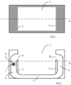
- Figure 1 shows in top view a swimming pool according to the invention.
- Figure 2 shows in side view a vertical longitudinal cross section of a swimming pool according to the invention in accordance with the dotted line A as shown in Figure 1 .
- Figure 3 shows in top view a horizontal longitudinal cross section of a swimming pool according to the invention in accordance with the dotted line B as shown in Figure 2 .
- a swimming pool to swim on the spot ideally has dimensions that allow for the necessary swimming movements without getting too close to the edge or bottom. Taking into account the dimensions of an adult human being, this means already a minimum length of 3 m, a minimum width of 2m and a minimal depth of 90 cm. To make it somewhat more comfortable but also taking into account running costs, mainly determined by energy consumption and water consumption, transport, and space required for installation, typical practical dimensions of a swimming pool for swimming on the spot are 4 m to 4.5 m long by 2.2 m to 2.5 m wide and 1.5 m to 1.8 m deep. Of course, the invention is by no means limited to these typical practical dimensions and these swimming pools can also be made larger or smaller.
- Figure 1 shows a top view of a swimming pool with these typical dimensions.
- the reservoir In the central part of the swimming pool reservoir 1 is located, which, when the swimming pool is operational, i.e. ready for use, is filled with water.
- the reservoir has metal or plastic walls.
- the reservoir is longitudinally provided with an inflow opening in a first end 2 and an outflow opening in a second opposite end 3. In operational state, the inflow opening and outflow opening are located completely below the surface level of the water present in the reservoir.
- the inflow opening and the outflow opening are preferably located centrally in the respective ends (sidewalls widthwise) of the reservoir.
- the upper edge of the inflow opening and outflow opening are located 5 cm to 25 cm below the water surface, preferably 10 cm to 15 cm.
- a counterflow is generated that counteracts the forward motion of the swimmer. This involves introducing water under pressure into the reservoir through the inflow opening and then this flows longitudinally towards the outflow opening through which the water is drained. The drained water is fed back to the inflow opening through a liquid connection.
- the surface area of the outflow opening is greater than or equal to the surface area of the inflow opening. Taking into account the average width of an adult human being of approximately 50 cm, the inflow opening is 60 cm to 90 cm high and 90 cm to 150 cm wide. The outflow opening is typically 10 cm to 20 cm wider and/or higher.
- the liquid connection of outflow opening 10 back to inflow opening 9 consists of a liquid line as shown for example in Figure 2 .
- the liquid line comprises a descending section 4 in connection with the reservoir via the outflow opening and located adjacent to the second end 3 of the reservoir 1, an ascending section 6 located at the first end 2 of the reservoir and in connection with the reservoir via the inflow opening, and a flow-through section 5 located under the reservoir between the ascending and descending section.
- a turbine 7 In the ascending section of the liquid line transversal relative to the longitudinal direction is located a turbine 7.
- the upper edge of the turbine is lower than or equal to the lower edge of the inflow opening. With a drive, an upward laminar flow is created by rotation of the turbine in the direction of the inflow opening.
- the generated laminar flow is injected into the reservoir through the inflow opening and then moves to the opposite end of the reservoir where the outflow opening is located.
- the rotation of the turbine simultaneously creates an underpressure below the turbine which draws water from the reservoir via the outflow opening and the liquid line. As such, continuous fluid circulation is created in the pool and the counterflow in the reservoir is maintained.
- the use, the orientation associated therewith, and the installation of a turbine 7 to generate counterflow offers significant advantages.
- the rotation axis of the turbine is perpendicular to the direction of propulsion which, unlike a screw or propeller, for example, generates a laminar flow in the direction of propulsion.
- the rotation axis of the turbine is also perpendicular to the longitudinal direction of the reservoir which ensures that the cross section of the mass of water can be better matched to the position, more specifically the swimming zone, of the swimmer in the pool for optimal comfort of the swimmer.
- the swimming zone is the space occupied in the swimming pool by the swimmer during swimming.
- the propelled mass of water can, after all, be routed through a rectangular or oval inflow opening.
- the inflow opening has a width greater than the height so that the swimmer throughout his swimming zone is in a laminar flow in which the water moves at substantially the same speed and in the same direction. This keeps the swimmer on the spot and he does not have to correct his position all the time. If the swimmer wishes to adjust his swimming speed, he can do so, for example, by adjusting the setting of the turbine rotation speed on a control panel, possibly using a remote control.
- proximity sensors e.g. optical sensors
- the turbine 7 is installed in the ascending section 6 of the liquid line so that the upper edge of the turbine does not protrude above the lower edge of the inflow opening 9. This ensures that the turbine is fully submerged in the operational state and by rotation propels a mass in an upward direction. Moreover, the turbine extends completely over the entire width and length of the liquid line in the ascending section. This ensures an optimal efficiency and avoids the generation of turbulence in the space between the turbine and the wall of the liquid line.
- the shortest distance between the turbine and the wall of the liquid line is 10 cm or smaller in length and width, preferably 5 cm or smaller.
- An additional advantage of a turbine is that due to the relatively large contact area between blades and water compared to, for example, propellers, the same flow rate can be realised with a lower rotational speed. This will benefit energy consumption.
- the blades are equidistantly and with equal angles attached to a cylindrically shaped central part. The efficiency can further be improved by using curved blades 8 and as such increase the contact surface with the water, and where the blades are also positioned so that the concave side of the blades supports the propulsive movement of the water.
- the turbine 7, as shown in Fig. 3 is provided with a drive shaft 11 protruding at the ends through openings in the wall in the ascending section 6 of the liquid line.
- waterproof bearings are provided in which the drive shaft is installed.
- a space 13 is provided in which a drive unit 12 is installed to rotate the turbine with adjustable speed so that, in operational state, a laminar flow is generated in ascending direction.
- This space 13 is hidden from view but still easily accessible from above or via the side and is located in the dry area of the swimming pool. The latter not only makes it cheaper and easier to maintain, but in addition it reduces the cost of acquisition of the motor as it is not submerged in the liquid.
- the drive unit 12 comprises an electric motor connected via a belt, chain and/or gears to one end of the turbine drive shaft.
- the electric motor can typically deliver maximum power between 1 kW and 5 kW.
- the electric motor can be fitted with a frequency converter that allows stepless control of the rotation speed of the turbine from a speed that is virtually zero to the maximum set range corresponding to a predetermined maximum achievable swimming speed. This also allows the rotation speed of the turbine to be dynamically controlled depending on the detected position of the swimmer if he speeds up or slows down.
- the maximum rotation speed of the turbine is typically between 1000 and 2000 rpm.
- the liquid line extends in the descending section 4 and largely in the flow-through section 5 across substantially the entire width of the reservoir.
- the height of the liquid line is typically 10 cm to 20 cm, such as 15 cm, for example.
- the width of the ascending section 6 of the liquid line is typically 90 cm to 160 cm, such as 120 cm, for example.
- the length of the ascending section of the liquid line is typically 40 cm to 90 cm, such as 65 cm, for example. Because the cross section of the ascending section is different from the cross section of the flow-through section, the width of the flow-through section decreases progressively and the height of the flow-through section increases progressively towards the ascending section to achieve a smooth and appropriate connection between the flow-through section and the ascending section.
- a fluid guiding element is provided in the flow-through section 5 of the liquid line, which, in particular, focuses the fluid supply to the turbine on the sides of the turbine after which it can distribute optimally along the length of the turbine.
- the fluid guiding element is made of metal or plastic and is centrally positioned at the end of the flow-through section adjacent to the ascending section.
- the fluid element is configured in a way that a first and a second fluid passage are formed at the side edges of the liquid line. The fluid can only flow from the flow-through section to the ascending section via these passages.
- the fluid guiding element is configured in a way that the cross section of the fluid guiding element increases with decreasing distance to the ascending section of the liquid line.
- Grids can be installed in the inflow opening and in the outflow opening. This provides shielding and, in particular, prevents objects from entering the liquid line or hurting people, for example due to entrapment in the fluid line or accidental contact with the rotating turbine.
- these grids are slatted grids.
Landscapes
- Health & Medical Sciences (AREA)
- General Health & Medical Sciences (AREA)
- Physical Education & Sports Medicine (AREA)
- Other Liquid Machine Or Engine Such As Wave Power Use (AREA)
Priority Applications (1)
| Application Number | Priority Date | Filing Date | Title |
|---|---|---|---|
| EP23195288.8A EP4520409B1 (fr) | 2023-09-05 | 2023-09-05 | Piscine à courant |
Applications Claiming Priority (1)
| Application Number | Priority Date | Filing Date | Title |
|---|---|---|---|
| EP23195288.8A EP4520409B1 (fr) | 2023-09-05 | 2023-09-05 | Piscine à courant |
Publications (2)
| Publication Number | Publication Date |
|---|---|
| EP4520409A1 true EP4520409A1 (fr) | 2025-03-12 |
| EP4520409B1 EP4520409B1 (fr) | 2025-12-10 |
Family
ID=88207755
Family Applications (1)
| Application Number | Title | Priority Date | Filing Date |
|---|---|---|---|
| EP23195288.8A Active EP4520409B1 (fr) | 2023-09-05 | 2023-09-05 | Piscine à courant |
Country Status (1)
| Country | Link |
|---|---|
| EP (1) | EP4520409B1 (fr) |
Citations (5)
| Publication number | Priority date | Publication date | Assignee | Title |
|---|---|---|---|---|
| US1731554A (en) | 1927-07-11 | 1929-10-15 | Milton I Wheeler | Swimming pool |
| KR20040051875A (ko) * | 2002-12-13 | 2004-06-19 | 박광순 | 스위밍 머신 |
| EP1878477A1 (fr) * | 2006-07-13 | 2008-01-16 | Chun-Ming Kuo | Appareil et procédé de circulation de l'eau pour une piscine |
| US8702387B2 (en) * | 2009-11-06 | 2014-04-22 | Vision Aquatics, Inc. | Propulsion system |
| US20150074895A1 (en) | 2013-09-18 | 2015-03-19 | Lmi Ip, Llc | Laminar Flow Swim Spa |
Family Cites Families (1)
| Publication number | Priority date | Publication date | Assignee | Title |
|---|---|---|---|---|
| US5005228A (en) * | 1985-09-10 | 1991-04-09 | Swimex Systems, Inc. | Flow controlling |
-
2023
- 2023-09-05 EP EP23195288.8A patent/EP4520409B1/fr active Active
Patent Citations (5)
| Publication number | Priority date | Publication date | Assignee | Title |
|---|---|---|---|---|
| US1731554A (en) | 1927-07-11 | 1929-10-15 | Milton I Wheeler | Swimming pool |
| KR20040051875A (ko) * | 2002-12-13 | 2004-06-19 | 박광순 | 스위밍 머신 |
| EP1878477A1 (fr) * | 2006-07-13 | 2008-01-16 | Chun-Ming Kuo | Appareil et procédé de circulation de l'eau pour une piscine |
| US8702387B2 (en) * | 2009-11-06 | 2014-04-22 | Vision Aquatics, Inc. | Propulsion system |
| US20150074895A1 (en) | 2013-09-18 | 2015-03-19 | Lmi Ip, Llc | Laminar Flow Swim Spa |
Also Published As
| Publication number | Publication date |
|---|---|
| EP4520409B1 (fr) | 2025-12-10 |
Similar Documents
| Publication | Publication Date | Title |
|---|---|---|
| CN100491677C (zh) | 波浪发生装置 | |
| US5005228A (en) | Flow controlling | |
| US10221582B2 (en) | Surface gravity wave generator and wave pool | |
| US20050170936A1 (en) | Swim trainer | |
| US11946277B2 (en) | Exercise pool with circulating flow | |
| CA1288551C (fr) | Regulation de debit | |
| EP2312981A1 (fr) | Piscine à vagues avec générateur de vagues à récif mobile | |
| US20250043582A1 (en) | Surface gravity wave generator and wave pool | |
| EP4520409A1 (fr) | Piscine à courant | |
| EA011460B1 (ru) | Встроенная установка для плавательного бассейна | |
| WO2014190314A2 (fr) | Système et procédé de génération de vagues pour des masses d'eau à forme libre | |
| BE1030294B1 (nl) | Zwembad | |
| AU2018200273B2 (en) | Surface gravity wave generator and wave pool | |
| US4845787A (en) | High flow, low turbulence swim-in-place pool operation method | |
| CN2849034Y (zh) | 用于游泳池可调整出水速度的连续循环水流产生装置 | |
| CH707912A2 (de) | Verstellbare Gegenstromanlage. | |
| AU2008203823A1 (en) | Swimflow generator | |
| JP2610543B2 (ja) | 強制還流式水流プール | |
| JPS6139501Y2 (fr) | ||
| RU2849442C1 (ru) | Бассейн для водных развлечений с искусственным течением | |
| US20230089423A1 (en) | Inlet for a hydrodynamic screw | |
| CN210508541U (zh) | 一种多功能循环水流游泳池 | |
| CA3219356A1 (fr) | Systemes et procedes de propulsion par jet de spa de nage | |
| RU2004681C1 (ru) | Водоприемник турбинного водовода гидроэлектростанции | |
| JP2023105480A (ja) | 流水プール設備 |
Legal Events
| Date | Code | Title | Description |
|---|---|---|---|
| STAA | Information on the status of an ep patent application or granted ep patent |
Free format text: STATUS: EXAMINATION IS IN PROGRESS |
|
| PUAI | Public reference made under article 153(3) epc to a published international application that has entered the european phase |
Free format text: ORIGINAL CODE: 0009012 |
|
| 17P | Request for examination filed |
Effective date: 20240827 |
|
| AK | Designated contracting states |
Kind code of ref document: A1 Designated state(s): AL AT BE BG CH CY CZ DE DK EE ES FI FR GB GR HR HU IE IS IT LI LT LU LV MC ME MK MT NL NO PL PT RO RS SE SI SK SM TR |
|
| GRAP | Despatch of communication of intention to grant a patent |
Free format text: ORIGINAL CODE: EPIDOSNIGR1 |
|
| STAA | Information on the status of an ep patent application or granted ep patent |
Free format text: STATUS: GRANT OF PATENT IS INTENDED |
|
| INTG | Intention to grant announced |
Effective date: 20250325 |
|
| GRAJ | Information related to disapproval of communication of intention to grant by the applicant or resumption of examination proceedings by the epo deleted |
Free format text: ORIGINAL CODE: EPIDOSDIGR1 |
|
| STAA | Information on the status of an ep patent application or granted ep patent |
Free format text: STATUS: EXAMINATION IS IN PROGRESS |
|
| GRAS | Grant fee paid |
Free format text: ORIGINAL CODE: EPIDOSNIGR3 |
|
| STAA | Information on the status of an ep patent application or granted ep patent |
Free format text: STATUS: GRANT OF PATENT IS INTENDED |
|
| GRAP | Despatch of communication of intention to grant a patent |
Free format text: ORIGINAL CODE: EPIDOSNIGR1 |
|
| INTC | Intention to grant announced (deleted) | ||
| INTG | Intention to grant announced |
Effective date: 20250801 |
|
| GRAA | (expected) grant |
Free format text: ORIGINAL CODE: 0009210 |
|
| STAA | Information on the status of an ep patent application or granted ep patent |
Free format text: STATUS: THE PATENT HAS BEEN GRANTED |
|
| AK | Designated contracting states |
Kind code of ref document: B1 Designated state(s): AL AT BE BG CH CY CZ DE DK EE ES FI FR GB GR HR HU IE IS IT LI LT LU LV MC ME MK MT NL NO PL PT RO RS SE SI SK SM TR |
|
| REG | Reference to a national code |
Ref country code: CH Ref legal event code: F10 Free format text: ST27 STATUS EVENT CODE: U-0-0-F10-F00 (AS PROVIDED BY THE NATIONAL OFFICE) Effective date: 20251210 Ref country code: GB Ref legal event code: FG4D |
|
| REG | Reference to a national code |
Ref country code: DE Ref legal event code: R096 Ref document number: 602023009495 Country of ref document: DE |
|
| REG | Reference to a national code |
Ref country code: IE Ref legal event code: FG4D |
|
| REG | Reference to a national code |
Ref country code: NL Ref legal event code: FP |
|
| PG25 | Lapsed in a contracting state [announced via postgrant information from national office to epo] |
Ref country code: ES Free format text: LAPSE BECAUSE OF FAILURE TO SUBMIT A TRANSLATION OF THE DESCRIPTION OR TO PAY THE FEE WITHIN THE PRESCRIBED TIME-LIMIT Effective date: 20251210 |
|
| REG | Reference to a national code |
Ref country code: LT Ref legal event code: MG9D |
|
| PG25 | Lapsed in a contracting state [announced via postgrant information from national office to epo] |
Ref country code: NO Free format text: LAPSE BECAUSE OF FAILURE TO SUBMIT A TRANSLATION OF THE DESCRIPTION OR TO PAY THE FEE WITHIN THE PRESCRIBED TIME-LIMIT Effective date: 20260310 |
|
| PG25 | Lapsed in a contracting state [announced via postgrant information from national office to epo] |
Ref country code: FI Free format text: LAPSE BECAUSE OF FAILURE TO SUBMIT A TRANSLATION OF THE DESCRIPTION OR TO PAY THE FEE WITHIN THE PRESCRIBED TIME-LIMIT Effective date: 20251210 Ref country code: HR Free format text: LAPSE BECAUSE OF FAILURE TO SUBMIT A TRANSLATION OF THE DESCRIPTION OR TO PAY THE FEE WITHIN THE PRESCRIBED TIME-LIMIT Effective date: 20251210 |
|
| PG25 | Lapsed in a contracting state [announced via postgrant information from national office to epo] |
Ref country code: RS Free format text: LAPSE BECAUSE OF FAILURE TO SUBMIT A TRANSLATION OF THE DESCRIPTION OR TO PAY THE FEE WITHIN THE PRESCRIBED TIME-LIMIT Effective date: 20260310 |