EP4520423A1 - Module de filtration - Google Patents
Module de filtration Download PDFInfo
- Publication number
- EP4520423A1 EP4520423A1 EP24195954.3A EP24195954A EP4520423A1 EP 4520423 A1 EP4520423 A1 EP 4520423A1 EP 24195954 A EP24195954 A EP 24195954A EP 4520423 A1 EP4520423 A1 EP 4520423A1
- Authority
- EP
- European Patent Office
- Prior art keywords
- filter
- filter module
- transverse wall
- transverse
- module according
- Prior art date
- Legal status (The legal status is an assumption and is not a legal conclusion. Google has not performed a legal analysis and makes no representation as to the accuracy of the status listed.)
- Granted
Links
Images





Classifications
-
- B—PERFORMING OPERATIONS; TRANSPORTING
- B01—PHYSICAL OR CHEMICAL PROCESSES OR APPARATUS IN GENERAL
- B01D—SEPARATION
- B01D46/00—Filters or filtering processes specially modified for separating dispersed particles from gases or vapours
- B01D46/10—Particle separators, e.g. dust precipitators, using filter plates, sheets or pads having plane surfaces
-
- B—PERFORMING OPERATIONS; TRANSPORTING
- B01—PHYSICAL OR CHEMICAL PROCESSES OR APPARATUS IN GENERAL
- B01D—SEPARATION
- B01D46/00—Filters or filtering processes specially modified for separating dispersed particles from gases or vapours
- B01D46/0002—Casings; Housings; Frame constructions
- B01D46/0005—Mounting of filtering elements within casings, housings or frames
-
- B—PERFORMING OPERATIONS; TRANSPORTING
- B01—PHYSICAL OR CHEMICAL PROCESSES OR APPARATUS IN GENERAL
- B01D—SEPARATION
- B01D46/00—Filters or filtering processes specially modified for separating dispersed particles from gases or vapours
- B01D46/56—Filters or filtering processes specially modified for separating dispersed particles from gases or vapours with multiple filtering elements, characterised by their mutual disposition
- B01D46/62—Filters or filtering processes specially modified for separating dispersed particles from gases or vapours with multiple filtering elements, characterised by their mutual disposition connected in series
-
- B—PERFORMING OPERATIONS; TRANSPORTING
- B05—SPRAYING OR ATOMISING IN GENERAL; APPLYING FLUENT MATERIALS TO SURFACES, IN GENERAL
- B05B—SPRAYING APPARATUS; ATOMISING APPARATUS; NOZZLES
- B05B14/00—Arrangements for collecting, re-using or eliminating excess spraying material
- B05B14/40—Arrangements for collecting, re-using or eliminating excess spraying material for use in spray booths
- B05B14/43—Arrangements for collecting, re-using or eliminating excess spraying material for use in spray booths by filtering the air charged with excess material
-
- B—PERFORMING OPERATIONS; TRANSPORTING
- B01—PHYSICAL OR CHEMICAL PROCESSES OR APPARATUS IN GENERAL
- B01D—SEPARATION
- B01D2273/00—Operation of filters specially adapted for separating dispersed particles from gases or vapours
- B01D2273/10—Allowing a continuous bypass of at least part of the flow, e.g. of secondary air, vents
Definitions
- the present invention relates to a filter module for separating particles from contaminated air.
- Filter modules are used for a variety of applications. For example, they can be used in spray booths to capture paint overspray.
- the filter modules serve to clean the air discharged from the spray booth. Paint particles that do not adhere to the object being sprayed can be separated by the filter modules.
- Such filter modules can therefore also be referred to as separators or separator modules.
- Filter modules typically have an inlet side designed for the entry of the air stream to be cleaned.
- An outlet side is preferably arranged on an opposite side, which serves as the exit for the cleaned air stream.
- filter modules can be arranged next to each other or on top of each other to create a continuous surface, which can be positioned, for example, below or to the side of the object to be sprayed. All inlet sides are arranged on one side of the continuous surface.
- a negative pressure is created behind the filter modules, so that an air flow through the filter modules is created, flowing from the inlet side towards the outlet side.
- the air flow Air is passed through the filter modules and cleaned by the particles adhering to the filter modules or being separated from the filter modules.
- Filter modules made of paper stock are known from the prior art. At least two walls are arranged within the filter module, which are arranged transversely to the direction of the incoming airflow and form baffles. The walls each have openings, whereby the openings in the walls become smaller from the inlet side towards the outlet side and/or can be arranged offset from one another. The walls create chambers within the base body. The airflow to be cleaned is guided in a meandering pattern through the differently arranged openings in the successively arranged walls.
- a stabilizing wall arranged perpendicular to the walls.
- cleaning structures can be arranged one behind the other within the hollow body, thus forming the filter module.
- the air to be cleaned is directed through the openings in the walls and the stabilizing wall in a meandering pattern, alternating between the walls and the stabilizing walls, and through the filter module.
- Another disadvantage is that part of the flow area is covered by an air-impermeable material, whereby particles can adhere to the surface of the so-called baffles, but the air is deflected.
- the present invention is based on the object of providing an improved filter module with an improved service life.
- the object of the invention is to provide a filter module with improved separation behavior while requiring less energy for operation.
- a filter module for separating particles from contaminated air in particular for separating paint particles from an air stream, with a receiving element which has an inlet side for the inlet of an air stream to be cleaned, and an outlet side for the outlet of the cleaned air stream, wherein the inlet side and the outlet side are arranged opposite one another on the receiving element, at least one filter insert which is received in the receiving element, wherein the filter insert has at least one transverse wall, and the transverse wall is formed from an at least partially air-permeable filter element, wherein an open partial area is formed in the filter element or next to the filter element, so that the air stream from the inlet side in the direction the outlet side can flow through the filter element on the one hand and through the open part area on the other.
- the finding underlying the present invention is that by omitting baffles, a durable and effective filter module can be formed.
- the idea underlying the present invention is not to abruptly slow or divert the air flow, but instead to form it without deflection, and/or in particular laminarly, between the inlet side and the outlet side in order to enable balanced adhesion of the particles to all transverse walls within the receiving element.
- This implements the idea of an open air duct without baffles, with the air flow flowing through a filter element on the one hand and through an open sub-area on the other.
- a transverse wall can be formed that is essentially completely permeable to air, namely from an at least partially permeable material, the filter element, and an opening, the open sub-area.
- the air flow within the receiving element can be influenced by the open partial area.
- the filter element can influence the shape of the open part solely through its shape.
- the filter element can be cut to any desired size to achieve different geometries.
- the open partial area can therefore be formed as a recess in the filter element or next to, in particular adjacent to, the filter element.
- Adjacent specifically means that the open section is formed in a plane of the transverse wall by tailoring the transverse wall accordingly, so that the filter element does not span an entire cross-sectional plane in the receiving element.
- the open section can therefore be manufactured easily and cost-effectively.
- the ratio of the area of the open partial area to the area of the entire transverse wall can be 1:2 to 1:20, in particular 1:2 to 1:10, preferably 1:5 to 1:12.
- the open partial area can form half of the transverse wall, or even 1/4 or 1/5 of the area of the transverse wall.
- a transverse wall is an element arranged transversely to the air flow within the receiving element.
- the transverse wall is designed to be completely permeable to air, with different areas with different air permeability levels being able to be customized as required. Therefore, the transverse wall preferably consists of a filter medium, with no baffle being implemented.
- the air flow can pass through the cross wall at any point.
- the differences in the flow velocities of the flows passing through the open section and through the filter element are small, so that a particularly laminar flow can be achieved.
- the separation performance can be increased enormously compared to designs with cross walls and multiple through-openings from the state of the art.
- the separation performance can be improved by more than 100% compared to known filter modules. This can be achieved in particular by the open air flow from the inlet side to the outlet side.
- the airflow is not deflected by baffles.
- the air flows through the air-permeable filter element, allowing particles to settle on the filter element. This can continue until the filter element is saturated with particles and no more air can flow through.
- the open section prevents the cross-wall from becoming "clogged,” ensuring a continuous flow of air through the open section.
- transverse walls With several such transverse walls arranged one behind the other, a more uniform separation can occur, whereby even a transverse wall positioned very far toward the outlet side can contribute significantly to the separation of particles.
- the transverse walls are saturated with particles one after the other, with the air reaching the last transverse wall through the open section in each transverse wall, so that even the transverse wall positioned furthest toward the outlet side can be saturated with particles. Therefore, the service life can be increased by at least 100% compared to filter modules with state-of-the-art impact walls.
- the open airflow allows the airflow to be directed to the outlet side without deflection, especially over long periods of time when the filter modules are in operation. This also reduces energy consumption.
- energy savings of at least 30% can be achieved compared to state-of-the-art filter modules, which are particularly designed with baffles. For example, energy savings of 40% to 50% can be achieved compared to state-of-the-art designs.
- the filter element can be formed from or contain a filament.
- the filter element can contain a natural fiber, for example, hemp, jute, and/or bast.
- the filament can contain a plastic.
- the filament is particularly characterized by a continuous fiber that can be connected as a three-dimensional structure. A 3D printing process can be used for this purpose. Other air-permeable materials are also conceivable.
- the filter element can have a woven or finely structured structure, which is particularly three-dimensional.
- the thickness of the filter element can be, for example, 10 mm to 200 mm or 50 mm to 200 mm, in particular 10 mm to 50 mm or 10 mm to 20 mm. This allows a three-dimensional filter element to be formed.
- the woven structure or filament can have interconnected fiber sections, with air-permeable spaces arranged between the fibers.
- the filter element can have varying degrees of fine or coarse mesh.
- such a filter module has a single filter insert that does not need to be replaced over the entire service life of the filter module, whereby all elements of the filter insert can be used until they become unusable, i.e. until they become clogged with separated particles.
- the at least one transverse wall can have at least two open partial areas, so that the air flow from the inlet side toward the outlet side can flow, on the one hand, through the filter element and, on the other hand, through an open portion of the opening.
- the open portions can be formed as recesses in the filter element.
- at least one open portion can be formed next to the filter element, wherein the geometry of the filter element can be adapted such that the open portion can form a residual area in a cross-sectional plane of the filter module that the filter element does not span.
- the open partial regions can be mirrored to one another in the filter element.
- two open partial regions are mirrored with respect to a central axis of the transverse wall.
- the open partial regions are arranged in particular on a first half of the transverse wall, so that one half of the transverse wall has no open partial regions in a second half of the transverse wall.
- the at least one open partial area can have the shape of a triangle, a rectangle, or a freeform.
- open partial areas can be formed in, particularly opposite, corner areas of the transverse wall.
- the filter element can, for example, have the shape of a partial circle and the open partial area a shape, which remains outside the partial circle shape up to a rectangular shape.
- the elements can, for example, be connected to one another or to one another in a force-fitting or material-fitting manner.
- holding elements such as clamps can be used.
- the elements can be glued together.
- complex folding or transverse walls can be dispensed with.
- the open portion may be partially bounded by the frame element and partially by the filter element.
- the open portion may be adjacent to the frame element and/or located in a corner area of the transverse wall.
- the at least one transverse wall can have at least two openings, wherein at least one opening is partially covered with a filter element, so that the air flow from the inlet side towards the outlet side can flow through the openings, firstly through the filter element and secondly through an open portion of the opening.
- the further opening can be completely covered with the filter element, so that the air flow must flow through the filter element.
- the filter element of the openings can be formed in one piece, so that the filter element completely covers one opening and is only partially arranged to cover another opening.
- the transverse wall can therefore have a frame element with a web.
- the remaining web between the two openings is formed, in particular, with a small width in relation to the width of the opening, in particular in a ratio of 1:10 or greater than 1:10, preferably 1:40 to 1:50, in particular greater than 1:30 or greater than 1:40.
- the web between the openings can therefore also serve to minimally absorb the particles, but preferably the web serves to stabilize the filter element if the latter has a special geometry, such as a partial circle or a circular shape. However, an embodiment without such a web is preferable.
- the web therefore does not form a baffle, so that the air flow is essentially unaffected by the web, i.e., can flow through the filter element unaffected by the web.
- the web and the frame element can be formed as a single piece from a paper material. so that the openings can be easily punched or cut out.
- a plurality of transverse walls can be arranged parallel to one another in the receiving element, wherein, in the case of transverse walls arranged one behind the other, at least one open partial region of a transverse wall is arranged offset from an open partial region of an adjacent transverse wall.
- the open partial region of the first transverse wall can be formed in a left-hand partial region, in particular in a first half, of the transverse wall
- the open partial region of the second transverse wall can be formed in a right-hand partial region, in particular in a second half, of the transverse wall.
- the open partial region can be formed in an upper partial region of the transverse wall, which can in particular overlap the left and right partial regions.
- the open partial region can be formed in a lower partial region of the transverse wall, which can in particular overlap the left and right partial regions.
- a fifth transverse wall can correspond to the first transverse wall, wherein the arrangement can be repeated as often as desired.
- identical cross walls can be arranged one behind the other, rotated by 90° to each other, in order to distribute the open sections within the filter module all around.
- transverse walls are arranged one behind the other in such a way that the open partial area is formed at different positions on the transverse wall.
- the positions can be arranged next to one another and/or overlap. This allows the air flow to be decelerated differently at different positions.
- a less thoroughly cleaned partial area of the air flow can reach a transverse wall arranged further toward the outlet side, so that the efficiency of the filter module can be optimized. All transverse walls can therefore contribute significantly to the cleaning of the air flow.
- the filter insert can have at least three, in particular three to twelve, transverse walls.
- the transverse walls can all have the same open sections, but arranged offset from one another.
- the open sections can decrease in size so that a desired degree of purification or efficiency of the filter module can be achieved.
- Such an arrangement can be referred to as a progressive design.
- the transverse walls can be arranged at different distances from one another, at least in part.
- the transverse walls located closer to the inlet side are preferably arranged at a greater distance from one another than the transverse walls located closer to the outlet side.
- a reverse arrangement is also conceivable.
- the filter module can be adapted to the number of particles encountered, thereby avoiding clogging.
- the respective at least one open partial area of adjacent transverse walls can be arranged at different positions on the transverse wall.
- the different positions can overlap when the transverse walls are stacked one above the other.
- the different positions can be adjacent to one another when the transverse walls are stacked one above the other.
- the open sections of consecutively arranged transverse walls can become smaller from the inlet side to the outlet side.
- the filtration efficiency can be adjusted from the inlet side to the outlet side solely through openings in the filter element, and thus, in particular, solely through the geometry of the filter element, without the need to adjust the geometry of a transverse wall made of an air-impermeable material in terms of openings or the like.
- the open sections of consecutively arranged transverse walls are aligned at a 180° angle to one another, allowing the achievement of a filter optimized in terms of filter performance, particularly in terms of separation behavior, service life, and energy consumption.
- the at least one transverse wall can be oriented transversely to a connecting plane between the inlet side and the outlet side.
- the transverse wall can be oriented transversely to an air flow.
- the transverse wall is oriented orthogonally to the air flow.
- the transverse walls can be connected to one another on at least one side edge via a longitudinal connection, so that a coherent filter insert is formed.
- a longitudinal connection can be pivotally attached to the transverse walls so that the filter insert can be pushed together so that the transverse walls are arranged parallel and touch each other for transport.
- two longitudinal connections can be arranged on two opposite sides, into which the transverse walls are inserted.
- the frame elements in particular can serve for fastening to the longitudinal connection.
- the transverse walls can extend over a complete length between the inlet side and the outlet side and/or the at least one longitudinal wall can extend over a complete width of the receiving element, so that only one filter insert spans an interior space of the receiving element.
- the receiving element and/or the filter insert can contain a recyclable material and/or the filter module can be designed as a paper filter module.
- the receiving element is preferably made of cardboard.
- Such a filter module can be easily disposed of, especially incinerated, even with adhering particles. Furthermore, the manufacturing costs are minimal.
- the filter element can be made of a filament, a nonwoven, and/or a natural fiber.
- the filter element can contain a woven fabric, nonwoven fabric, or the like, which is also recyclable.
- the filter element can have a woven or finely structured structure, which is particularly three-dimensional and can contain the aforementioned materials.
- At least one sensor for measuring the velocity of the purified airflow and/or for measuring a resistance value can be arranged at the outlet opening. This advantageously makes it possible to determine when a filter module needs to be replaced. If, for example, the velocity of the purified airflow is below a threshold value, it can be assumed that the filter module is so contaminated that hardly any more air can flow through it.
- a chamber for accommodating a filter element can be arranged on the outlet side within the receiving element. This creates a fine filtration stage that filters out the smallest particles from the air stream.
- the receiving element can be resealable or reopenable, with at least one closure element formed on a side surface of the receiving element.
- the closure element can be completely recessed within the side wall of the receiving element, so that it does not hinder the arrangement of multiple filter modules on top of one another or next to one another to form a continuous surface.
- a method for assembling a filter module can be provided.
- a substantially two-dimensional structure without cavities can be present by full-surface contact of the at least one longitudinal connection with the transverse walls.
- This structure is transformed into a three-dimensional structure with spaced-apart transverse walls during assembly, without the transverse walls or the at least one longitudinal connection being bent.
- the receiving element can also be designed as a substantially two-dimensional structure, similar to a cardboard box. This allows both elements—the receiving element and the filter insert—to be transported in a space-saving manner. Assembly of the filter module is also time-saving and can be done without prior knowledge.
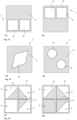
- the Figures 1 to 4 show different embodiments of transverse walls 7 of a filter insert 6.
- the transverse walls 7 each have an opening 8 in a frame element 11, wherein the opening 8 forms almost the entire surface of the transverse wall 7.
- two open partial areas 10 are formed, which in this embodiment are arranged symmetrically with respect to a horizontal or a vertical axis. It is also conceivable to form the openings asymmetrically.
- only one open partial area 10 can be formed in each transverse wall 7, as shown by way of example in Fig. 13 or 14 shown.
- the open sections 10 are shown as square, triangular or rectangular openings in the filter element 9. Other geometries, for example as in Fig. 13 or Fig. 14 , are also conceivable.
- the embodiments show a filter element 9 that is attached to a frame element 11.
- the filter element 9 can be glued to the frame element, for example, in particular pointwise or continuously.
- fixing means such as clamps, can be used.
- the filter element 99 can have a frame section, in particular in the area of the open partial areas 10, which can be contacted with the frame element 11.
- the frame section can run along the frame element 11.
- the frame section of the filter element 9 can serve as a fastening surface of the filter element, so that the filter element can be fastened all around to the frame element.
- a design without the frame element 11 is also conceivable, as in Figs. 13 and 14 shown as an example.
- Fig. 1 shows, for example, a transverse wall 7 with large open sections 10, the size of the sections in the Fig. 2 to 4 decreases in size.
- cross walls with a coarse filter, for example Fig. 2 a medium filtering, for example Fig. 3 , and fine filtering, for example Fig. 4 , be trained.
- the transverse walls of the Fig. 1 to 4 have a filter element 9 in which two open partial areas 10 are formed.
- the open partial area 10 can be formed next to the filter element 9, as in Fig. 11 , 15 or 17 shown.
- receptacles 23 and recesses 24 can be arranged on the lateral edge sections of the transverse wall 7, in particular on the frame element 11 or also on the filter element 9.
- the transverse walls 7 can therefore be connected to one another via longitudinal connections 14, as shown for example in Fig. 7 shown. Therefore, longitudinal connections 14 can be attached to opposite side areas of the transverse walls 7.
- four longitudinal connections 14 can be arranged, wherein the transverse walls, for example, have receptacles 23 and recesses 24 as in Fig. 4 (b) can have.
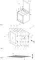
- FIG. 5 An arrangement of the transverse walls is shown one behind the other, so that a filter element can be formed.
- the filter properties can be arranged one behind the other from coarse to fine, as shown by way of example.
- at least one embodiment according to Fig. 1 be arranged in front of the transverse wall 7 shown on the left.
- the air initially flows through all transverse walls 7, as these are made of a filter material that is, in particular, at least partially permeable to air.
- the entire surface of the transverse wall can therefore be flowed through, whereby the filter module has no baffles. Therefore, the entire cross-section of the transverse wall can also be used to separate particles.
- the baffle can be formed from separated particles.
- the open partial area 10 advantageously enables air to be guided through the transverse wall even when the transverse wall is saturated, so that the transverse walls 7 arranged behind it also receive a continuous flow and contribute to the separation. This allows the entire filter element to become gradually saturated.
- the filter modules can therefore be replaced much later than with conventional filter modules that have baffles from the outset.
- the filter according to the invention can therefore absorb a much larger amount of particles.
- transverse walls are arranged rotated 90° to each other, so that the open partial areas 10 of adjacent transverse walls 7 are either arranged next to each other or partially overlap.
- the Fig. 5 The transverse walls shown can also have receptacles 23 and recesses 24 as in Fig. 4 (a) or 4 (b) shown.
- the arrangement of the transverse walls 7 from Fig. 1 to Fig. 4 can be just as in Fig. 12 shown so that the transverse walls are arranged rotated 180° to each other.
- Fig. 6 shows a filter module 1 with a receiving element 2 and a filter insert 6 with an open cover 29.
- an opening 13 is arranged, which can, for example, correspond to the opening 8 (not shown) of the transverse wall 7, which is arranged closest to the inlet side 3.
- an outlet side 5 is arranged on the receiving element 2, which has an opening 28.
- the opening 28 is preferably formed over almost the entire side surface of the receiving element 2 in order to ensure that the purified air 4b is discharged as quickly as possible.
- Fig. 7 shows an isometric view of a filter insert 6.
- the transverse walls 7 are essentially perpendicular to each other arranged.
- the transverse walls 7 can be connected to one another via longitudinal connections 14, also referred to as centering clamps.
- each of the transverse walls 7 can have receptacles 23 and recesses 24, in particular on the frame element 11 or also on the filter element 9.
- the three-dimensional structure can be produced by the longitudinal connections 14.
- the longitudinal connection 14 can, for example, have recesses 22 into which an operator can reach with their fingers. This makes it easier to set the longitudinal connections 14.
- the longitudinal connection 14 also has a fold 25 that extends over the length of the longitudinal connection 14.
- the longitudinal connection 14 folds along the fold 25, making it easier to place.
- the longitudinal connection 14 is preferably slightly longer than the distance between the two receptacles 23 so that it can be securely clamped between them.
- Fig. 8 shows a side view of the filter attachment 6 from Fig. 10 in a folded state. It can be seen that the transverse walls 7 are tilted relative to the longitudinal connections 14 in order to convert a two-dimensional structure according to Fig. 8 a three-dimensional structure according to Fig. 7 When the filter insert 6 is assembled into a three-dimensional structure with rectangular or square cavities 19, the transverse walls 7 are therefore not bent. Overall, the filter insert 6 therefore has a high level of stability. Furthermore, the folded filter insert can be easily transported. This allows a volume reduction of > 30%, in particular between 30% and 80%, depending on the design and configuration of the transverse walls.
- Fig. 9 shows two plan views of two further embodiments.
- the direction of the air flow 4 is shown by the arrows.
- Each of the air flows 4 is a laminar flow, with no meandering diversion to adjacent air flows, i.e. parallel or transverse to the transverse walls 7, and accordingly no deflection of the air flow to the left or right in the illustration.
- An open air flow can thus be implemented, with the air flow being able to be guided completely through air-permeable material within the filter insert 6.
- the receiving element 2 has a chamber 15 on the outlet side 5, in which chamber a filter element 16, in particular referred to as a post-filter, is arranged. In this way, the air 4a to be cleaned can be finely cleaned in a final step.
- Fig. 10 (a) and 10 (b) each show a plan view of a further embodiment.
- the transverse walls 7 are arranged at different distances from one another.
- the transverse walls 7 are arranged at a greater distance from one another in the region of the inlet side 3, since in this region most of the particles from the air to be cleaned adhere to the filter insert 6.
- the transverse walls 7 are arranged closer together. This allows for fine cleaning of the air flow.
- a distribution of the particles over the entire filter insert 6 can be specially adapted so that the filter module 1 can be used effectively over a particularly long period of time.
- Each transverse wall of the Figs. 9 and 10 can be used, for example, as in Fig. 1 to 4 11 to 15 or 17 be trained.
- a web is provided, which can be connected to the frame element 11, in particular in one piece.
- the web is comparatively thin, so that it only serves to stabilize the filter element 9, but is not designed to separate particles. Accordingly, the open air flow is not impaired by the web.
- the web can form a fraction of the surface of the transverse wall 7, in particular in a ratio of 1:20 to 1:50, preferably 1:20 to 1:25 or 1:30 to 1:40.
- the filter element 9 is circular in shape, so that each opening 8 is partially covered by a partially circular filter element 9. At the corners, an open air flow through the open sections 10 is therefore possible.
- Fig. 11 (b) the upper opening 8 is designed without a filter element 9, while the lower opening is covered with a filter element 9.
- Fig. 12 shows side-by-side arranged transverse walls 7 with open partial areas 10 in a further embodiment according to Fig. 13
- the open partial areas 10 of each transverse wall 7 are arranged in different positions on the transverse wall 7, wherein in this embodiment the open partial areas 10 of the transverse walls 7 do not overlap in an assembled state of the filter insert 6.
- the air to be cleaned can thereby be Fig. 5 describe, whereby a high degree of efficiency can be achieved.
- transverse walls 7 can be arranged between them or at the end, in which no open part 10 is provided, but the transverse wall 7 is completely covered by the filter element 9.
- a progressive structure can be implemented.
- transverse walls 7 can be arranged one behind the other. A different number is also conceivable. The spacing of the transverse walls 7 can become smaller toward the outlet side.
- Fig. 16 shows an embodiment of a filter module 6 in an isometric representation with a detailed view of a closure element 18.
- the closure elements 18 are arranged on the upper side 20 of the receiving element 2.
- the upper side 20 has four elements that together form a cover 29.
- Two closure elements 18 are arranged on each of the elements.
- Two further elements of the cover 29 each have two slots 27.
- the slots 27 are arranged offset from one another. Consequently, the closure elements 18 are also arranged offset from one another in the same way.
- the closure element 18 consists of a tab 26, which can engage in a slot 27 in another element of the lid 29.
- the tab 26 is inserted into the slot 27 from above and bent in the direction of the arrow.
- the receiving element 2 has a flat upper side 20.
- the upper side 20 is designed similarly to a packaging carton, having two inner tabs and two outer tabs, which together form a lid 29.
- the receiving element 2 has four substantially rectangular openings 13 on the side surface forming an inlet side 3. Before using the filter module 1, these openings can be closed by removable elements. to prevent contamination of the filter insert 6. These removable elements can be easily removed manually via access holes or recesses. For this purpose, the shape of the openings 13 is preferably pre-marked by a perforation. Likewise, the opening 13 on the outlet side 5 can be designed as shown in Fig. 6 and initially closed by a removable element.
- FIG. 17 A further embodiment of a transverse wall 7 is shown, wherein the filter element 9 has a triangular shape or a distorted quadrilateral shape.
- the open partial area 10 can therefore be arranged adjacent to the filter element, i.e., next to the filter element 9.
- a frame element 11 is preferably provided, so that the open partial area 10 is partially delimited by the frame element 11 and partially by the filter element 9.
- the filter element 9 can be attached to the frame element.
- the open partial areas 10 described above can have different configurations.
- the shape can also differ from the illustrated form.
- the arrangement of the open partial areas 10 can differ from the illustrated manner.
Landscapes
- Chemical & Material Sciences (AREA)
- Chemical Kinetics & Catalysis (AREA)
- Filtering Of Dispersed Particles In Gases (AREA)
Applications Claiming Priority (1)
| Application Number | Priority Date | Filing Date | Title |
|---|---|---|---|
| DE102023124274.1A DE102023124274A1 (de) | 2023-09-08 | 2023-09-08 | Filtermodul |
Publications (2)
| Publication Number | Publication Date |
|---|---|
| EP4520423A1 true EP4520423A1 (fr) | 2025-03-12 |
| EP4520423B1 EP4520423B1 (fr) | 2026-04-22 |
Family
ID=92538440
Family Applications (1)
| Application Number | Title | Priority Date | Filing Date |
|---|---|---|---|
| EP24195954.3A Active EP4520423B1 (fr) | 2023-09-08 | 2024-08-22 | Module de filtration |
Country Status (2)
| Country | Link |
|---|---|
| EP (1) | EP4520423B1 (fr) |
| DE (1) | DE102023124274A1 (fr) |
Citations (4)
| Publication number | Priority date | Publication date | Assignee | Title |
|---|---|---|---|---|
| WO2007028176A1 (fr) * | 2005-09-09 | 2007-03-15 | Dexwet Usa Llc | Module filtrant |
| DE102011050915A1 (de) * | 2011-06-08 | 2012-12-13 | Neufilter Gmbh | Papiergelegefiltermodul, Verfahren zur Herstellung eines solchen Papiergelegefiltermoduls und Papiergelegefiltermodulwand aus einer Mehrzahl derartiger Papiergelegefiltermodule |
| DE202015104109U1 (de) * | 2015-08-06 | 2015-08-18 | Jens Neumann | Partikelfilter- oder Partikelabscheidemodul |
| KR20210009725A (ko) * | 2019-07-17 | 2021-01-27 | 조한재 | 집진장치 |
Family Cites Families (7)
| Publication number | Priority date | Publication date | Assignee | Title |
|---|---|---|---|---|
| US3744222A (en) * | 1970-12-16 | 1973-07-10 | A Delao | Corrugated board paint filter |
| AT515431B1 (de) * | 2014-04-07 | 2015-09-15 | Brain Flash Patententwicklungs Gmbh | Reinigungssystem für Lackpartikel |
| DE102015112113A1 (de) * | 2015-07-24 | 2017-01-26 | Dürr Systems Ag | Filterstrukturkörper und Filtermodul zum Abscheiden von Verunreinigungen aus einem Rohgasstrom |
| EP4019146A1 (fr) * | 2020-12-23 | 2022-06-29 | IPCS GmbH Innovative Paint & Conveyor Systems | Module filtrant et utilisation d'un module filtre pour la séparation de peinture et/ou de résidus de peinture, en particulier de l'excédent de peinture dans une cabine de peinture |
| DE102021206818A1 (de) * | 2021-06-30 | 2023-01-05 | Jens Neumann | Abscheidevorrichtung |
| DE102021211593A1 (de) * | 2021-10-14 | 2023-04-20 | Jürgen Kara | Filtermodul |
| DE202022105864U1 (de) * | 2022-10-18 | 2022-11-10 | Neufilter Gmbh | Luftstromabscheideelement |
-
2023
- 2023-09-08 DE DE102023124274.1A patent/DE102023124274A1/de active Pending
-
2024
- 2024-08-22 EP EP24195954.3A patent/EP4520423B1/fr active Active
Patent Citations (4)
| Publication number | Priority date | Publication date | Assignee | Title |
|---|---|---|---|---|
| WO2007028176A1 (fr) * | 2005-09-09 | 2007-03-15 | Dexwet Usa Llc | Module filtrant |
| DE102011050915A1 (de) * | 2011-06-08 | 2012-12-13 | Neufilter Gmbh | Papiergelegefiltermodul, Verfahren zur Herstellung eines solchen Papiergelegefiltermoduls und Papiergelegefiltermodulwand aus einer Mehrzahl derartiger Papiergelegefiltermodule |
| DE202015104109U1 (de) * | 2015-08-06 | 2015-08-18 | Jens Neumann | Partikelfilter- oder Partikelabscheidemodul |
| KR20210009725A (ko) * | 2019-07-17 | 2021-01-27 | 조한재 | 집진장치 |
Also Published As
| Publication number | Publication date |
|---|---|
| DE102023124274A1 (de) | 2025-03-13 |
| EP4520423B1 (fr) | 2026-04-22 |
Similar Documents
| Publication | Publication Date | Title |
|---|---|---|
| EP2675547B1 (fr) | Élément de filtre à air, carter de filtre à air et système de filtre à air | |
| EP0514412B1 (fr) | Garniture de filtre | |
| EP3837036B1 (fr) | Corps à structure filtrante et module filtrant servant à séparer des impuretés d'un flux de gaz brut | |
| EP1481200A2 (fr) | Systeme de filtrage pour hotte aspirante | |
| DE102014009026A1 (de) | Filterelement mit wenigstens einem Führungssteg, Filter mit einem Filterelement und Filtergehäuse eines Filters | |
| DE102015112113A1 (de) | Filterstrukturkörper und Filtermodul zum Abscheiden von Verunreinigungen aus einem Rohgasstrom | |
| DE102014009803A1 (de) | Filterelement mit Griffelementen und Filter mit einem Filterelement | |
| DE102015004641A1 (de) | Filterelement, insbesondere zur Gasfiltration | |
| EP4415850B1 (fr) | Étage filtrant | |
| EP4349449A1 (fr) | Filtre avec coulisse de filtre améliorée | |
| EP2987546B1 (fr) | Élement de filtre destine a la separation de particules dans un flux de gaz brut charge en particules | |
| DE102019001309A1 (de) | Filtervorrichtung | |
| DE102022203975B4 (de) | Filterstufe | |
| EP4415851B1 (fr) | Module de filtre | |
| EP4520423A1 (fr) | Module de filtration | |
| DE19848774A1 (de) | Filtereinheit zum auswechselbaren Einsetzen in das Gehäuse einer Filteranlage | |
| AT514845A1 (de) | Rotorelement und Rotor für eine Siebvorrichtung | |
| DE102023124277B4 (de) | Filtermodul | |
| WO2023274834A1 (fr) | Dispositif de séparation | |
| EP4267275B1 (fr) | Unité de pré-séparation | |
| DE1955789B2 (de) | Filter aus zickzackfoermig gefaltetem, streifenfoermigen filterpapier | |
| DE102024108406A1 (de) | Oversprayfiltermedium | |
| DE102017110266A1 (de) | Vorrichtung zur Abscheidung von Farbpartikeln aus einem Luftstrom | |
| DE29714914U1 (de) | Siebvorrichtung zum Sortieren von nassen schmutzstoffhaltigen Faserstoffen | |
| DE202014004898U1 (de) | Schräg duchströmtes Filterelement |
Legal Events
| Date | Code | Title | Description |
|---|---|---|---|
| PUAI | Public reference made under article 153(3) epc to a published international application that has entered the european phase |
Free format text: ORIGINAL CODE: 0009012 |
|
| STAA | Information on the status of an ep patent application or granted ep patent |
Free format text: STATUS: THE APPLICATION HAS BEEN PUBLISHED |
|
| AK | Designated contracting states |
Kind code of ref document: A1 Designated state(s): AL AT BE BG CH CY CZ DE DK EE ES FI FR GB GR HR HU IE IS IT LI LT LU LV MC ME MK MT NL NO PL PT RO RS SE SI SK SM TR |
|
| STAA | Information on the status of an ep patent application or granted ep patent |
Free format text: STATUS: REQUEST FOR EXAMINATION WAS MADE |
|
| 17P | Request for examination filed |
Effective date: 20250912 |
|
| GRAP | Despatch of communication of intention to grant a patent |
Free format text: ORIGINAL CODE: EPIDOSNIGR1 |
|
| STAA | Information on the status of an ep patent application or granted ep patent |
Free format text: STATUS: GRANT OF PATENT IS INTENDED |
|
| RIC1 | Information provided on ipc code assigned before grant |
Ipc: B01D 46/00 20220101AFI20251106BHEP Ipc: B01D 46/10 20060101ALI20251106BHEP Ipc: B01D 46/62 20220101ALI20251106BHEP Ipc: B05B 14/43 20180101ALI20251106BHEP |
|
| INTG | Intention to grant announced |
Effective date: 20251114 |
|
| GRAS | Grant fee paid |
Free format text: ORIGINAL CODE: EPIDOSNIGR3 |
|
| GRAA | (expected) grant |
Free format text: ORIGINAL CODE: 0009210 |
|
| STAA | Information on the status of an ep patent application or granted ep patent |
Free format text: STATUS: THE PATENT HAS BEEN GRANTED |
|
| AK | Designated contracting states |
Kind code of ref document: B1 Designated state(s): AL AT BE BG CH CY CZ DE DK EE ES FI FR GB GR HR HU IE IS IT LI LT LU LV MC ME MK MT NL NO PL PT RO RS SE SI SK SM TR |
|
| REG | Reference to a national code |
Ref country code: CH Ref legal event code: F10 Free format text: ST27 STATUS EVENT CODE: U-0-0-F10-F00 (AS PROVIDED BY THE NATIONAL OFFICE) Effective date: 20260422 Ref country code: GB Ref legal event code: FG4D Free format text: NOT ENGLISH |