EP4520452A2 - Matériau d'extrémité de canette résistant au craquelage - Google Patents
Matériau d'extrémité de canette résistant au craquelage Download PDFInfo
- Publication number
- EP4520452A2 EP4520452A2 EP25152784.2A EP25152784A EP4520452A2 EP 4520452 A2 EP4520452 A2 EP 4520452A2 EP 25152784 A EP25152784 A EP 25152784A EP 4520452 A2 EP4520452 A2 EP 4520452A2
- Authority
- EP
- European Patent Office
- Prior art keywords
- metal strip
- end stock
- crazing
- polymer film
- stock
- Prior art date
- Legal status (The legal status is an assumption and is not a legal conclusion. Google has not performed a legal analysis and makes no representation as to the accuracy of the status listed.)
- Pending
Links
Images


Classifications
-
- B—PERFORMING OPERATIONS; TRANSPORTING
- B32—LAYERED PRODUCTS
- B32B—LAYERED PRODUCTS, i.e. PRODUCTS BUILT-UP OF STRATA OF FLAT OR NON-FLAT, e.g. CELLULAR OR HONEYCOMB, FORM
- B32B37/00—Methods or apparatus for laminating, e.g. by curing or by ultrasonic bonding
- B32B37/06—Methods or apparatus for laminating, e.g. by curing or by ultrasonic bonding characterised by the heating method
-
- B—PERFORMING OPERATIONS; TRANSPORTING
- B21—MECHANICAL METAL-WORKING WITHOUT ESSENTIALLY REMOVING MATERIAL; PUNCHING METAL
- B21D—WORKING OR PROCESSING OF SHEET METAL OR METAL TUBES, RODS OR PROFILES WITHOUT ESSENTIALLY REMOVING MATERIAL; PUNCHING METAL
- B21D35/00—Combined processes according to or processes combined with methods covered by groups B21D1/00 - B21D31/00
- B21D35/002—Processes combined with methods covered by groups B21D1/00 - B21D31/00
- B21D35/005—Processes combined with methods covered by groups B21D1/00 - B21D31/00 characterized by the material of the blank or the workpiece
- B21D35/007—Layered blanks
-
- B—PERFORMING OPERATIONS; TRANSPORTING
- B21—MECHANICAL METAL-WORKING WITHOUT ESSENTIALLY REMOVING MATERIAL; PUNCHING METAL
- B21D—WORKING OR PROCESSING OF SHEET METAL OR METAL TUBES, RODS OR PROFILES WITHOUT ESSENTIALLY REMOVING MATERIAL; PUNCHING METAL
- B21D51/00—Making hollow objects
- B21D51/16—Making hollow objects characterised by the use of the objects
- B21D51/26—Making hollow objects characterised by the use of the objects cans or tins; Closing same in a permanent manner
-
- B—PERFORMING OPERATIONS; TRANSPORTING
- B32—LAYERED PRODUCTS
- B32B—LAYERED PRODUCTS, i.e. PRODUCTS BUILT-UP OF STRATA OF FLAT OR NON-FLAT, e.g. CELLULAR OR HONEYCOMB, FORM
- B32B15/00—Layered products comprising a layer of metal
- B32B15/04—Layered products comprising a layer of metal comprising metal as the main or only constituent of a layer, which is next to another layer of the same or of a different material
- B32B15/08—Layered products comprising a layer of metal comprising metal as the main or only constituent of a layer, which is next to another layer of the same or of a different material of synthetic resin
- B32B15/09—Layered products comprising a layer of metal comprising metal as the main or only constituent of a layer, which is next to another layer of the same or of a different material of synthetic resin comprising polyesters
-
- B—PERFORMING OPERATIONS; TRANSPORTING
- B32—LAYERED PRODUCTS
- B32B—LAYERED PRODUCTS, i.e. PRODUCTS BUILT-UP OF STRATA OF FLAT OR NON-FLAT, e.g. CELLULAR OR HONEYCOMB, FORM
- B32B15/00—Layered products comprising a layer of metal
- B32B15/20—Layered products comprising a layer of metal comprising aluminium or copper
-
- B—PERFORMING OPERATIONS; TRANSPORTING
- B32—LAYERED PRODUCTS
- B32B—LAYERED PRODUCTS, i.e. PRODUCTS BUILT-UP OF STRATA OF FLAT OR NON-FLAT, e.g. CELLULAR OR HONEYCOMB, FORM
- B32B37/00—Methods or apparatus for laminating, e.g. by curing or by ultrasonic bonding
- B32B37/0046—Methods or apparatus for laminating, e.g. by curing or by ultrasonic bonding characterised by constructional aspects of the apparatus
- B32B37/0053—Constructional details of laminating machines comprising rollers; Constructional features of the rollers
-
- B—PERFORMING OPERATIONS; TRANSPORTING
- B32—LAYERED PRODUCTS
- B32B—LAYERED PRODUCTS, i.e. PRODUCTS BUILT-UP OF STRATA OF FLAT OR NON-FLAT, e.g. CELLULAR OR HONEYCOMB, FORM
- B32B37/00—Methods or apparatus for laminating, e.g. by curing or by ultrasonic bonding
- B32B37/08—Methods or apparatus for laminating, e.g. by curing or by ultrasonic bonding characterised by the cooling method
-
- B—PERFORMING OPERATIONS; TRANSPORTING
- B32—LAYERED PRODUCTS
- B32B—LAYERED PRODUCTS, i.e. PRODUCTS BUILT-UP OF STRATA OF FLAT OR NON-FLAT, e.g. CELLULAR OR HONEYCOMB, FORM
- B32B38/00—Ancillary operations in connection with laminating processes
- B32B38/0036—Heat treatment
-
- B—PERFORMING OPERATIONS; TRANSPORTING
- B32—LAYERED PRODUCTS
- B32B—LAYERED PRODUCTS, i.e. PRODUCTS BUILT-UP OF STRATA OF FLAT OR NON-FLAT, e.g. CELLULAR OR HONEYCOMB, FORM
- B32B38/00—Ancillary operations in connection with laminating processes
- B32B38/0036—Heat treatment
- B32B2038/0048—Annealing, relaxing
-
- B—PERFORMING OPERATIONS; TRANSPORTING
- B32—LAYERED PRODUCTS
- B32B—LAYERED PRODUCTS, i.e. PRODUCTS BUILT-UP OF STRATA OF FLAT OR NON-FLAT, e.g. CELLULAR OR HONEYCOMB, FORM
- B32B2309/00—Parameters for the laminating or treatment process; Apparatus details
- B32B2309/02—Temperature
-
- B—PERFORMING OPERATIONS; TRANSPORTING
- B32—LAYERED PRODUCTS
- B32B—LAYERED PRODUCTS, i.e. PRODUCTS BUILT-UP OF STRATA OF FLAT OR NON-FLAT, e.g. CELLULAR OR HONEYCOMB, FORM
- B32B2311/00—Metals, their alloys or their compounds
- B32B2311/24—Aluminium
-
- B—PERFORMING OPERATIONS; TRANSPORTING
- B32—LAYERED PRODUCTS
- B32B—LAYERED PRODUCTS, i.e. PRODUCTS BUILT-UP OF STRATA OF FLAT OR NON-FLAT, e.g. CELLULAR OR HONEYCOMB, FORM
- B32B2367/00—Polyesters, e.g. PET, i.e. polyethylene terephthalate
-
- B—PERFORMING OPERATIONS; TRANSPORTING
- B32—LAYERED PRODUCTS
- B32B—LAYERED PRODUCTS, i.e. PRODUCTS BUILT-UP OF STRATA OF FLAT OR NON-FLAT, e.g. CELLULAR OR HONEYCOMB, FORM
- B32B2435/00—Closures, end caps, stoppers
- B32B2435/02—Closures, end caps, stoppers for containers
-
- B—PERFORMING OPERATIONS; TRANSPORTING
- B32—LAYERED PRODUCTS
- B32B—LAYERED PRODUCTS, i.e. PRODUCTS BUILT-UP OF STRATA OF FLAT OR NON-FLAT, e.g. CELLULAR OR HONEYCOMB, FORM
- B32B2439/00—Containers; Receptacles
- B32B2439/40—Closed containers
- B32B2439/66—Cans, tins
-
- B—PERFORMING OPERATIONS; TRANSPORTING
- B32—LAYERED PRODUCTS
- B32B—LAYERED PRODUCTS, i.e. PRODUCTS BUILT-UP OF STRATA OF FLAT OR NON-FLAT, e.g. CELLULAR OR HONEYCOMB, FORM
- B32B37/00—Methods or apparatus for laminating, e.g. by curing or by ultrasonic bonding
- B32B37/02—Methods or apparatus for laminating, e.g. by curing or by ultrasonic bonding characterised by a sequence of laminating steps, e.g. by adding new layers at consecutive laminating stations
-
- B—PERFORMING OPERATIONS; TRANSPORTING
- B65—CONVEYING; PACKING; STORING; HANDLING THIN OR FILAMENTARY MATERIAL
- B65D—CONTAINERS FOR STORAGE OR TRANSPORT OF ARTICLES OR MATERIALS, e.g. BAGS, BARRELS, BOTTLES, BOXES, CANS, CARTONS, CRATES, DRUMS, JARS, TANKS, HOPPERS, FORWARDING CONTAINERS; ACCESSORIES, CLOSURES, OR FITTINGS THEREFOR; PACKAGING ELEMENTS; PACKAGES
- B65D25/00—Details of other kinds or types of rigid or semi-rigid containers
- B65D25/14—Linings or internal coatings
Definitions
- the present disclosure relates generally to metalworking and, more specifically, to laminated metal strips suitable for use as can end stock and to their production.
- beverage cans may require or otherwise benefit from a protective layer between the metal and its contents.
- beverage cans often must provide sufficient protection between the metal of the beverage can and the beverage contained therein to avoid damage to the metal from harsh beverages, such as sodas and colas, as well as to avoid undesirable effects to the beverage, such as discoloration or change in taste.
- the protective layer must adequately adhere to the metal product.
- Conventional protective layers have been found to demonstrate undesirable susceptibility to damage, such as by crazing and/or feathering. Thus, conventional protective layers are ineffective.
- the present disclosure provides a process for preparing a crazing-resistant can end stock, comprising: applying a pretreatment coating to a first side of a metal strip; laminating a polymer film to the first side of the metal strip to form a laminated metal strip, wherein the polymer film is adhered to at least a portion of the pretreatment coating; and annealing the laminated metal strip at an annealing temperature, wherein the annealing temperature is less than 250 °C.
- the can end stock exhibits no visible crazing.
- the first side of the metal strip corresponds to an interior-facing side of a can end formed from the metal strip.
- the metal strip is an aluminum strip.
- the polymer film comprises a polyethylene terephthalate film.
- the pretreatment coating comprises a polymer or co-polymer.
- the annealing temperatures is less than 230 °C. In some cases, the annealing temperature is greater than 150 °C.
- the present disclosure provides a can end stock product prepared according to any of the process described herein.
- the first side of the metal strip corresponds to an exterior-facing side of the can end stock product.
- the polymer film has a thickness less than 50 ⁇ m.
- the present disclosure provide a beverage can comprising a body piece and an end cap, wherein the end cap is formed from can end stock prepared according to any of the process described herein.
- the present disclosure provides a can end stock, comprising: a metal strip; a pretreatment composition; and a polymer film, wherein the can end stock exhibits no visible crazing.
- the can end stock exhibits no visible crazing within 24 hours after a strain test, wherein the strain test comprises application of a 2% strain with a 10 N/mm2 ⁇ s force.
- the can end stock exhibits no visible crazing under UV light within 24 hours after the strain test, wherein the strain test further comprises coating the samples with a fluorescent marker.
- the metal strip is an aluminum strip.
- the polymer film comprises a polyethylene terephthalate.
- the pretreatment composition is a polymer or co-polymer.
- the polymer film exhibits an FTIR absorbance peak intensity ratio (A/B) greater than 0.4, wherein A indicates a first absorbance peak at a wavenumber from 1330 cm 1 to 1350 cm 1 and B indicates a second absorbance peak at a wavenumber from 1400 cm 1 to 1420 cm-1.
- the absorbance peak intensity ratio (A/B) is greater than 1.0.
- the present disclosure provides a system, comprising: a lamination system for accepting a metal strip and applying a polymer film to a first side of the metal strip; and an annealing furnace positioned downstream of the lamination system for accepting a laminated metal strip and heating the laminated metal strip at an annealing temperature, wherein the annealing temperature is less than 250 °C.
- the metal strip is an aluminum strip.
- the system further comprises a pretreatment coating application system for applying a pretreatment coating to the metal strip, wherein the lamination system is configured to apply the polymer film to the pretreatment coating.
- the lamination system is coupled to a supply of polyethylene terephthalate film.
- the annealing temperature is less than 230 °C. In some cases, the annealing temperature is greater than 150 °C.
- the present disclosure provides a method for assessing the susceptibility of a can end stock to crazing, the method comprising: stamping a can end stock to produce a test sample; applying a strain to the test sample to produce a stressed sample; and observing the stressed sample for crazing.
- applying a strain comprises applying a 2% strain with a 10 N/mm2 ⁇ s force.
- observing the stressed sample comprises shining a light on the stressed sample.
- the method further comprises coating the test sample and/or the stressed sample with a fluorescent marker, and wherein observing the stressed sample comprises shining a UV light on the stressed sample.
- Described herein are processes and systems for producing can end stock from a metal strip, such as an aluminum strip.
- a polymer film such as a polyethylene terephthalate film
- the resultant can end stock can be used, for example, in beverage cans.
- the can end stock produced according the methods described herein advantageously exhibit improved properties.
- the can end stock exhibits resistance to crazing (as defined below).
- the can end stock described herein also exhibits low feathering.
- the methods described herein also provide a more efficient means of applying protective film(s) to a metal strip.
- conventional polymer films such as polyethylene terephthalate
- Conventional polymer films are particularly prone to crazing during a seaming process, whereby can end stock and can body stock are joined. It has been found that seaming processes initiate, encourage, or otherwise exacerbate crazing of the polymer films.
- process conditions impact the susceptibility of polymer films to crazing.
- annealing laminated metal strips at lower temperatures beneficially reduces the susceptibility of the produced can end stock to crazing.
- conventional processes encourage high annealing temperatures to produce a polymer film with higher adhesion and resistance to feathering
- the novel processes described herein anneal at relatively lower temperatures and produce a can end stock with good adhesion as well as resistance to crazing.
- the present disclosure provides processes for producing crazing-resistant can end stock.
- invention As used herein, the terms "invention,” “the invention,” “this invention” and “the present invention” are intended to refer broadly to all of the subject matter of this patent application and the claims below. Statements containing these terms should be understood not to limit the subject matter described herein or to limit the meaning or scope of the patent claims below.
- Aluminum alloys are described herein in terms of their elemental composition in weight percentage (wt. %) based on the total weight of the alloy. In certain examples of each alloy, the remainder is aluminum, with a maximum wt. % of 0.15 % for the sum of the impurities.
- brazing refers to the formation and/or propagation of small cracks on or close to the surface of and/or on the opposite face of a protective layer (e.g., polymer film) on the metal strip, especially during a process for seaming, e.g., of a can end stock to a can body stock.
- the cracks extend through the protective layer (e.g., polymer film). i.e., from the surface of the protect layer to the surface facing the metal strip.
- feathering refers to the elongation and delamination of in a protective layer (e.g., polymer film) on the metal strip, especially at breaks in the metal, such as the orifice created when opening a beverage can.
- a protective layer e.g., polymer film
- An F condition or temper refers to an aluminum alloy as fabricated.
- An O condition or temper refers to an aluminum alloy after annealing.
- a T1 condition or temper refers to an aluminum alloy cooled from hot working and naturally aged (e.g., at room temperature).
- a T2 condition or temper refers to an aluminum alloy cooled from hot working, cold worked, and naturally aged.
- a T3 condition or temper refers to an aluminum alloy solution heat treated, cold worked, and naturally aged.
- a T4 condition or temper refers to an aluminum alloy solution heat treated and naturally aged.
- a T5 condition or temper refers to an aluminum alloy cooled from hot working and artificially aged (at elevated temperatures).
- a T6 condition or temper refers to an aluminum alloy solution heat treated and artificially aged.
- a T7 condition or temper refers to an aluminum alloy solution heat treated and artificially overaged.
- a T8x condition or temper refers to an aluminum alloy solution heat treated, cold worked, and artificially aged.
- a T9 condition or temper refers to an aluminum alloy solution heat treated, artificially aged, and cold worked.
- room temperature can include a temperature of from about 15 °C to about 30 °C, for example about 15 °C, about 16 °C, about 17 °C, about 18 °C, about 19 °C, about 20 °C, about 21 °C, about 22 °C, about 23 °C, about 24 °C, about 25 °C, about 26 °C, about 27 °C, about 28 °C, about 29 °C, or about 30 °C.
- the present disclosure provides processes and systems for producing can end stock from a metal strip. More specifically, the methods described herein include applying a pretreatment coating to a first side of a metal strip and laminating a polymer film to the first side of the metal strip.
- the composition of the metal strip on which the polymer film is laminated is not limited.
- the methods described herein are particularly well suited for, but not limited to, aluminum strips.
- the polymer film may be applied, for example, to any suitable aluminum alloy, such as a continuous coil of an aluminum alloy.
- Suitable aluminum alloys include, for example, 1xxx series aluminum alloys, 2xxx series aluminum alloys, 3xxx series aluminum alloys, 4xxx series aluminum alloys, 5xxx series aluminum alloys, 6xxx series aluminum alloys, 7xxx series aluminum alloys, and 8xxx series aluminum alloys.
- exemplary 1xxx series aluminum alloys for use as the metal strip can include AA1100, AA1100A, AA1200, AA1200A, AA1300, AA1110, AA1120, AA1230, AA1230A, AA1235, AA1435, AA1145, AA1345, AA1445, AA1150, AA1350, AA1350A, AA1450, AA1370, AA1275, AA1185, AA1285, AA1385, AA1188, AA1190, AA1290, AA1193, AA1198, or AA1199.
- the aluminum alloy is at least 99.9 % pure aluminum (e.g., at least 99.91 %, at least 99.92 %, at least 99.93 %, at least 99.94 %, at least 99.95 %, at least 99.96 %, at least 99.97 %, at least 99.98 %, or at least 99.99 % pure aluminum).
- Non-limiting exemplary 2xxx series aluminum alloys for use as the metal strip can include AA2001, AA2002, AA2004, AA2005, AA2006, AA2007, AA2007A, AA2007B, AA2008, AA2009, AA2010, AA2011, AA2011A, AA2111, AA2111A, AA2111B, AA2012, AA2013, AA2014, AA2014A, AA2214, AA2015, AA2016, AA2017, AA2017A, AA2117, AA2018, AA2218, AA2618, AA2618A, AA2219, AA2319, AA2419, AA2519, AA2021, AA2022, AA2023, AA2024, AA2024A, AA2124, AA2224, AA2224A, AA2324, AA2424, AA2524, AA2624, AA2724, AA2824, AA2025, AA2026,
- Non-limiting exemplary 3xxx series aluminum alloys for use as the metal strip can include AA3002, AA3102, AA3003, AA3103, AA3103A, AA3103B, AA3203, AA3403, AA3004, AA3004A, AA3104, AA3204, AA3304, AA3005, AA3005A, AA3105, AA3105A, AA3105B, AA3007, AA3107, AA3207, AA3207A, AA3307, AA3009, AA3010, AA3110, AA3011, AA3012, AA3012A, AA3013, AA3014, AA3015, AA3016, AA3017, AA3019, AA3020, AA3021, AA3025, AA3026, AA3030, AA3130, or AA3065.
- Non-limiting exemplary 4xxx series aluminum alloys for use as the metal strip can include AA4004, AA4104, AA4006, AA4007, AA4008, AA4009, AA4010, AA4013, AA4014, AA4015, AA4015A, AA4115, AA4016, AA4017, AA4018, AA4019, AA4020, AA4021, AA4026, AA4032, AA4043, AA4043A, AA4143, AA4343, AA4643, AA4943, AA4044, AA4045, AA4145, AA4145A, AA4046, AA4047, AA4047A, or AA4147.
- Non-limiting exemplary 5xxx series aluminum alloys for use as the metal strip can include AA5182, AA5183, AA5005, AA5005A, AA5205, AA5305, AA5505, AA5605, AA5006, AA5106, AA5010, AA5110, AA5110A, AA5210, AA5310, AA5016, AA5017, AA5018, AA5018A, AA5019, AA5019A, AA5119, AA5119A, AA5021, AA5022, AA5023, AA5024, AA5026, AA5027, AA5028, AA5040, AA5140, AA5041, AA5042, AA5043, AA5049, AA5149, AA5249, AA5349, AA5449, AA5449A, AA5050, AA5050A, AA5050C, AA5150, AA5051, AA
- Non-limiting exemplary 6xxx series aluminum alloys for use as the metal strip can include AA6101, AA6101A, AA6101B, AA6201, AA6201A, AA6401, AA6501, AA6002, AA6003, AA6103, AA6005, AA6005A, AA6005B, AA6005C, AA6105, AA6205, AA6305, AA6006, AA6106, AA6206, AA6306, AA6008, AA6009, AA6010, AA6110, AA6110A, AA6011, AA6111, AA6012, AA6012A, AA6013, AA6113, AA6014, AA6015, AA6016, AA6016A, AA6116, AA6018, AA6019, AA6020, AA6021, AA6022, AA6023, AA6024, AA6025, AA6026, AA6027, AA6028,
- Non-limiting exemplary 7xxx series aluminum alloys for use as the metal strip can include AA7011, AA7019, AA7020, AA7021, AA7039, AA7072, AA7075, AA7085, AA7108, AA7108A, AA7015, AA7017, AA7018, AA7019A, AA7024, AA7025, AA7028, AA7030, AA7031, AA7033, AA7035, AA7035A, AA7046, AA7046A, AA7003, AA7004, AA7005, AA7009, AA7010, AA7011, AA7012, AA7014, AA7016, AA7116, AA7122, AA7023, AA7026, AA7029, AA7129, AA7229, AA7032, AA7033, AA7034, AA7036, AA7136, AA7037, AA70
- Non-limiting exemplary 8xxx series aluminum alloys for use as the metal strip can include AA8005, AA8006, AA8007, AA8008, AA8010, AA8011, AA8011A, AA8111, AA8211, AA8112, AA8014, AA8015, AA8016, AA8017, AA8018, AA8019, AA8021, AA8021A, AA8021B, AA8022, AA8023, AA8024, AA8025, AA8026, AA8030, AA8130, AA8040, AA8050, AA8150, AA8076, AA8076A, AA8176, AA8077, AA8177, AA8079, AA8090, AA8091, or AA8093.
- the metal strip comprises AA3104, AA5006, AA5182, or combinations thereof.
- the metal strip is aluminum, an aluminum alloy, magnesium, a magnesium-based material, titanium, a titanium-based material, copper, a copper-based material, steel, a steel-based material, bronze, a bronze-based material, brass, a brass-based material, a composite, a sheet used in composites, or any other suitable metal or combination of materials.
- the product may include monolithic materials, as well as non-monolithic materials such as roll-bonded materials, clad materials, composite materials, or various other materials.
- the metal article is a metal coil, a metal strip, a metal plate, a metal sheet, a metal billet, a metal ingot, or the like.
- the metal strip can be prepared from an alloy of any suitable temper.
- the alloys can be used in F, O, T3, T4, T6, or T8x tempers.
- the alloys can be produced by direct chill casting (including direct chill co-casting) or semi-continuous casting, continuous casting (including, for example, by use of a twin belt caster, a twin roll caster, a block caster, or any other continuous caster), electromagnetic casting, hot top casting, or any other casting method.
- the processes described herein, and the can end stock produced therefrom comprise applying a pretreatment coating to the metal strip.
- the processes of the present disclosure include applying the pretreatment coating on a side (e.g., the first side) of the metal strip and laminating a polymer film thereon. Said another way, the polymer film may be adhered to at least a portion of the pretreatment coating.
- the pretreatment coating is applied to a side of the metal strip that corresponds to an interior-facing side of a can end formed from the metal strip.
- the pretreatment coating forms a portion of the product side of the can end stock.
- the pretreatment coating can provide improved feathering performance.
- the adhesion of the polymer film to the metal strip can be controlled (e.g., improved) by the selection of an appropriate pretreatment coating and by controlling process parameters (such as the annealing temperature, described below).
- the pretreatment coating is a pretreatment applied to the metal strip, e.g., a pretreatment suited to the metal strip.
- the pretreatment coating may comprise a polymer or co-polymer, e.g., a poly(vinylphosphonic acid-co-acrylic acid) co-polymer.
- suitable pretreatments include Addibond 712 - CP 30 from Solvay (Brussels, Belgium).
- the pretreatment coating has an average thickness of from 5 nm to 100 nm, e.g., from 5 nm to 95 nm, from 5 nm to 90 nm, from 5 nm to 85 nm, from 5 nm to 80 nm, from 5 nm to 75 nm, from 6 nm to 100 nm, from 6 nm to 95 nm, from 6 nm to 90 nm, from 6 nm to 85 nm, from 6 nm to 80 nm, from 6 nm to 75 nm, from 8 nm to 100 nm, from 8 nm to 95 nm, from 8 nm to 90 nm, from 8 nm to 85 nm, from 8 nm to 80 nm, from 8 nm to 75 nm, from 10 nm to 100 nm, from 10 nm to 95 nm, from 10 nm to 90 nm, from 10 nm to 100
- the pretreatment coating may have an average thickness greater than 5 nm, e.g., greater than 6 nm, greater than 8 nm, greater than 10 nm, or greater than 12 nm. In terms of upper limits, the pretreatment coating may have an average thickness less than 100 nm, e.g., less than 95 nm, less than 90 nm, less than 85 nm, less than 80 nm, or less than 75 nm.
- the processes described herein, and the can end stock produced therefrom comprise laminating a polymer film to the metal strip.
- the processes of the present disclosure include laminating the polymer film on a side (e.g., the first side) of the metal strip that corresponds to an interior-facing side of a can end formed from the metal strip.
- the polymer film forms a portion of the product side of the can end stock.
- the use of a polymer film on an interior-facing side of a can end e.g., as opposed to a lacquer
- the polymer films described herein e.g., produced according to the described process conditions
- lamination of a polymer film on the metal strip is more reproducible and cleaner because impurities are typically rare in polymer films.
- the polymer film is not particularly limited and may comprise any polymer suitable for the desired use of the can end stock (e.g., as a beverage can).
- Suitable polymers for the polymer film include, for example, polyethylene, polypropylene, and polyethylene terephthalate (PET).
- PET polyethylene terephthalate
- the polymer film laminated to the metal strip is a biaxially oriented polymer, such as a biaxially-oriented polyethylene terephthalate (BoPET) film.
- Commercial suppliers of polymer films suitable for use herein include, for example, Toray Plastics (Front Royal, VA), Mitsubishi Polyester Film (Greer, SC), and DuPont Performance Polymers (Wilmington, DE).
- the polymer film further comprises a colorant, such as a dye or a pigment.
- a colorant such as a dye or a pigment.
- the polymer film may be a colored polymer film (e.g., a colored PET film).
- the colorant used in the colored polymer film is not particularly limited. Suitable colorants include, for example, titanium dioxide (e.g., to produce a white polymer film).
- the polymer film has an average thickness of from 5 ⁇ m to 50 ⁇ m, e.g., from 5 ⁇ m to 48 ⁇ m, from 5 ⁇ m to 46 ⁇ m, from 5 ⁇ m to 44 ⁇ m, from 5 ⁇ m to 42 ⁇ m, from 5 ⁇ m to 40 ⁇ m, from 6 ⁇ m to 50 ⁇ m, from 6 ⁇ m to 48 ⁇ m, from 6 ⁇ m to 46 ⁇ m, from 6 ⁇ m to 44 ⁇ m, from 6 ⁇ m to 42 ⁇ m, from 6 ⁇ m to 40 ⁇ m, from 8 ⁇ m to 50 ⁇ m, from 8 ⁇ m to 48 ⁇ m, from 8 ⁇ m to 46 ⁇ m, from 8 ⁇ m to 44 ⁇ m, from 8 ⁇ m to 42 ⁇ m, from 8 ⁇ m to 40 ⁇ m, from 10 ⁇ m to 50 ⁇ m, from 10 ⁇ m to 48 ⁇ m, from 10 ⁇ m to 46 ⁇ m, from 10 ⁇ m to 48
- the polymer film may have an average thickness greater than 5 ⁇ m, e.g., greater than 6 ⁇ m, greater than 8 ⁇ m, greater than 10 ⁇ m, or greater than 12 ⁇ m.
- the polymer film may have an average thickness less than 50 ⁇ m, e.g., less than 48 ⁇ m, less than 46 ⁇ m, less than 44 ⁇ m, less than 42 ⁇ m, or less than 40 ⁇ m.
- suitable average thicknesses of the polymer film include 5 ⁇ m, 6 ⁇ m, 7 ⁇ m, 8 ⁇ m, 9 ⁇ m, 10 ⁇ m, 11 ⁇ m, 12 ⁇ m, 13 ⁇ m, 14 ⁇ m, 15 ⁇ m, 16 ⁇ m, 17 ⁇ m, 18 ⁇ m, 19 ⁇ m, 20 ⁇ m, 21 ⁇ m, 22 ⁇ m, 23 ⁇ m, 24 ⁇ m, 25 ⁇ m, 26 ⁇ m, 27 ⁇ m, 28 ⁇ m, 29 ⁇ m, 30 ⁇ m, 31 ⁇ m, 32 ⁇ m, 33 ⁇ m, 34 ⁇ m, 35 ⁇ m, 36 ⁇ m, 37 ⁇ m, 38 ⁇ m, 39 ⁇ m, and 40 ⁇ m, and any thickness there between.
- the process of the present disclosure includes laminating multiple layers of polymer film on the metallic strip.
- each layer of polymer film may independently be a polymer film as described above.
- multiple layers of polymer film are laminated on the metallic strip, and one or more of the layers are identical (e.g., in terms of composition and/or thickness).
- multiple layers of polymer film are laminated on the metallic strip, and the layers are not identical (e.g., in terms of composition and/or thickness).
- conventional can end stock products preferentially include polymer films that have been temperature treated (e.g., a high temperature treatment, such as pretreatment). It was believed that high temperature treatment was necessary to provide certain properties, such as high adhesion and low feathering.
- temperature treated polymer films are highly susceptible to crazing. In particular, crazing is seen close to or on the surface of amorphous polymer films (e.g., PET films) that are laminated on an interior-facing (e.g., product) side of a can end stock. It has been found that temperature treatment (e.g., high temperature treatment) alters the conformation of polymer films. The modified conformation of the polymer films may be more susceptible to crazing.
- the polymer film does not comprise a high temperature treated polymer. Said another way, in some embodiments, the conformation of the polymer film is not substantially modified. In some cases, the polymer film has a similar conformation before and after production of the can end stock. In some cases, the polymer film has the same conformation before and after production. In some embodiments, this is accomplished by preventing or limiting the melting of the polymer film during lamination.
- this is accomplished by preventing or limiting the exposure of the polymer film to high temperatures, e.g., temperatures greater than 200 °C, greater than 210 °C, greater than 220 °C, greater than 230 °C, greater than 240 °C, or greater than 250 °C.
- high temperatures e.g., temperatures greater than 200 °C, greater than 210 °C, greater than 220 °C, greater than 230 °C, greater than 240 °C, or greater than 250 °C.
- the suitability of a polymer film for the can end stock may be assessed by a Fourier-transform infrared spectroscopy (FTIR) test developed by the present inventors.
- FTIR is a technique used in various quantitative analyses to obtain an infrared spectrum of absorbance or emission of a solid, liquid, or gas.
- an FTIR absorbance spectrum of the polymer film is analyzed to determine the suitability of the polymer film for use in the can end stock.
- the FTIR test assesses the ratio (A/B) of the absorbance peak intensity at a first wavenumber (A) to the absorbance peak intensity at a second wavenumber (B).
- the FTIR absorbance spectrum may be obtained by commercially available spectrometers, including, for example, the model 670 from Varian, Inc. (Palo Alto, CA).
- the FTIR spectrometer may include an attenuated total reflectance (ATR) attachment, such as a diamond ATR.
- ATR attenuated total reflectance
- the FTIR absorbance spectrum is obtained by measuring at one location on the polymer film.
- the FTIR absorbance spectrum is obtained by measuring at multiple locations (e.g., at least two, at least three, or at least four locations) on the polymer film and averaging the outputs from the spectra.
- the suitability of the polymer film for the can end stock may be determined by evaluating and comparing the relative intensity of two absorbance peaks. That is, the suitability of the polymer film may be determined from the ratio (A/B) of the FTIR absorbance peak intensity at a first wavenumber (A) to the absorbance peak intensity at a second wavenumber (B). In some cases, the suitability of the polymer film (as used herein) refers to the susceptibility of the polymer film to crazing before and/or after annealing.
- the first absorbance peak (A) of the FTIR ratio is a peak at a wavenumber from 1330 cm -1 to 1350 cm -1 .
- the first absorbance peak (A) may be a peak at a wavenumber greater than 1330 cm -1 , e.g., greater than 1332 cm -1 , greater than 1334 cm -1 , greater than 1336 cm -1 , or greater than 1338 cm -1 .
- the first absorbance peak (A) may be a peak at a wavenumber less than 1350 cm -1 , e.g., less than 1348 cm -1 , less than 1346 cm -1 , less than 1344 cm -1 , or less than 1342 cm -1 .
- the first absorbance peak (A) may be at wavenumber 1330 cm -1 , 1331 cm -1 , 1332 cm -1 , 1333 cm -1 , 1334 cm -1 , 1335 cm -1 , 1337 cm -1 , 1338 cm -1 , 1339 cm -1 , 1340 cm -1 , 1341 cm -1 , 1342 cm -1 , 1343 cm -1 , 1344 cm -1 , 1345 cm -1 , 1346 cm -1 , 1347 cm -1 , 1348 cm -1 , 1349 cm -1 , or 1345 cm -1 , or at any wavenumber there between.
- the second absorbance peak (B) of the FTIR ratio is a peak at a wavenumber from 1400 cm -1 to 1420 cm -1 .
- the second absorbance peak (B) may be a peak at a wavenumber greater than 1400 cm -1 , e.g., greater than 1402 cm -1 , greater than 1404 cm -1 , greater than 1406 cm -1 , or greater than 1408 cm -1 .
- the second absorbance peak (B) may be a peak at a wavenumber less than 1420 cm -1 , e.g., less than 1418 cm -1 , less than 1416 cm -1 , less than 1414 cm -1 , or less than 1412 cm -1 .
- the second absorbance peak (B) may be at wavenumber 1400 cm -1 , 1401 cm -1 , 1402 cm -1 , 1403 cm -1 , 1404 cm -1 , 1405 cm -1 , 1407 cm -1 , 1408 cm -1 , 1409 cm -1 , 1410 cm -1 , 1411 cm -1 , 1412 cm -1 , 1413 cm -1 , 1414 cm -1 , 1415 cm -1 , 1416 cm -1 , 1417 cm -1 , 1418 cm -1 , 1419 cm -1 , or 1415 cm -1 , or at any wavenumber therebetween.
- Polymer films that exhibit a high FTIR ratio are particularly suitable for can end stock described herein.
- utilizing a polymer film having a high FTIR ratio produces a can end stock with low susceptibility to crazing.
- the polymer film exhibits an absorbance peak intensity ratio (A/B) greater than 0.4, e.g., greater than 0.5, greater than 0.6, greater than 0.8, greater than 1.0, greater than 1.1, greater than 1.2, greater than 1.3, greater than 1.4, or greater than 1.5.
- the absorbance peak intensity ratio (A/B) of the polymer film may be less than 2.0, e.g., less than 1.9, less than 1.8, less than 1.7, or less than 1.6.
- the can end stock produced according the present disclosure comprises a layer of lacquer.
- a layer of lacquer may be applied to a surface of the metal strip, e.g., the external-facing surface.
- the lacquer forms a protective layer between the metal strip and the contents of the can end stock (e.g., the contents of a beverage can formed from can end stock).
- composition of the lacquer suitable for use in the processes described herein is not particularly limited.
- the lacquer comprises a water-based and/or solvent-based composition, which preferably may be sprayed, poured, or otherwise applied to a surface of the metal strip.
- the lacquer applied to a surface of the metal strip comprises an epoxy-based solution.
- a commercial example of a composition suitable for use as a lacquer for the present disclosure includes packaging coatings from AkzoNobel (Amsterdam, Netherlands).
- the layer of lacquer has an average thickness of from 2 ⁇ m to 20 ⁇ m, e.g., from 2 ⁇ m to 18 ⁇ m, from 2 ⁇ m to 16 ⁇ m, from 2 ⁇ m to 14 ⁇ m, from 2 ⁇ m to 12 ⁇ m, from 2 ⁇ m to 10 ⁇ m, from 3 ⁇ m to 20 ⁇ m, from 3 ⁇ m to 18 ⁇ m, from 3 ⁇ m to 16 ⁇ m, from 3 ⁇ m to 14 ⁇ m, from 3 ⁇ m to 12 ⁇ m, from 3 ⁇ m to 10 ⁇ m, from 4 ⁇ m to 20 ⁇ m, from 4 ⁇ m to 18 ⁇ m, from 4 ⁇ m to 16 ⁇ m, from 4 ⁇ m to 14 ⁇ m, from 4 ⁇ m to 12 ⁇ m, from 4 ⁇ m to 10 ⁇ m, from 5 ⁇ m to 20 ⁇ m, from 5 ⁇ m to 18 ⁇ m, from 5 ⁇ m to 16 ⁇ m, from 5 ⁇ m to
- the layer of lacquer may have an average thickness greater than 2 ⁇ m, e.g., greater than 3 ⁇ m, greater than 4 ⁇ m, greater than 5 ⁇ m, or greater than 6 ⁇ m.
- the layer of lacquer may have an average thickness less than 20 ⁇ m, e.g., less than 18 ⁇ m, less than 16 ⁇ m, less than 14 ⁇ m, less than 12 ⁇ m, or less than 10 ⁇ m.
- Examples of suitable average thicknesses of the layer of lacquer include 2 ⁇ m, 3 ⁇ m, 4 ⁇ m, 5 ⁇ m, 6 ⁇ m, 7 ⁇ m, 8 ⁇ m, 9 ⁇ m, 10 ⁇ m, 11 ⁇ m, 12 ⁇ m, 13 ⁇ m, 14 ⁇ m, 15 ⁇ m, 16 ⁇ m, 17 ⁇ m, 18 ⁇ m, 19 ⁇ m, and 20 ⁇ m, and any thickness therebetween.
- the thickness of the layer of lacquer may be expressed in terms of basis weight.
- the layer of lacquer has a basis weight of from 1 g/m 2 to 15 g/m 2 , e.g., from 1 g/m 2 to 14 g/m 2 , from 1 g/m 2 to 12 g/m 2 , from 1 g/m 2 to 10 g/m 2 , from 1 g/m 2 to 8 g/m 2 , from 1 g/m 2 to 6 g/m 2 , from 1.5 g/m 2 to 15 g/m 2 , from 1.5 g/m 2 to 14 g/m 2 , from 1.5 g/m 2 to 12 g/m 2 , from 1.5 g/m 2 to 10 g/m 2 , from 1.5 g/m 2 to 8 g/m 2 , from 1.5 g/m 2 to 6 g/m 2 , from 2 g/m 2 to 15 g/m 2 , from 2 g/m 2 to
- the layer of lacquer may have a basis weight greater than 1 g/m 2 , e.g., greater than 1.5 g/m 2 , greater than 2 g/m 2 , greater than 2.5 g/m 2 , or greater than 3 g/m 2 .
- the layer of lacquer may have a basis weight less than 15 g/m 2 , e.g., less than 14 g/m 2 , less than 12 g/m 2 , less than 10 g/m 2 , less than 8 g/m 2 , or less than 6 g/m2.
- suitable basis weight of the layer of lacquer examples include 1 g/m 2 , 1.5 g/m 2 , 2 g/m 2 , 2.5 g/m 2 , 3 g/m 2 , 3.5 g/m 2 , 4 g/m 2 , 4.5 g/m 2 , 5 g/m 2 , 5.5 g/m 2 , 6 g/m 2 , 6.5 g/m 2 , 7 g/m 2 , 7.5 g/m 2 , 8 g/m 2 , 9 g/m 2 , 10 g/m 2 , 11 g/m 2 , 12 g/m 2 , 13 g/m 2 , 14 g/m 2 , 15 g/m 2 , and any thickness therebetween.
- the can end stock produced according the present disclosure comprises an adhesion coating between the metal strip and the layer of lacquer.
- an adhesion coating may be applied to the metal strip, and the lacquer may be applied thereon.
- the adhesion coating beneficially fixes the lacquer to the metal strip.
- the adhesion coating is a pretreatment applied to the metal strip, e.g., a pretreatment suited to the metal strip.
- the adhesion coating between the metal strip and layer of lacquer may be the same as or different from the adhesion coating between the polymer film and the metal strip.
- suitable pretreatments that can be employed as the adhesion coating between the metal strip and the lacquer include titanium zirconium (Ti-Zr) based pretreatments or chromium (Cr3) based pretreatments, such as Bonderite from Henkel Adhesive Technologies (Düsseldorf, Germany).
- the present disclosure provides processes for preparing can end stock.
- the processes described herein advantageously produce crazing-resistant can end stock.
- the processes described herein produce a laminated can end stock that also exhibits high performance in other testing parameters, such as in an acetic acid test which can assess the corrosion resistance of the laminate against acidic conditions that can result in delamination.
- These processes can include applying a pretreatment coating to a metal strip, laminating a polymer film to the metal strip, and annealing the laminated metal strip at an annealing temperature (T A ).
- annealing the laminated metal strip comprises heating to a temperature T A that is less than 250 °C. Annealing at this temperature prevents the polymer film from becoming amorphous (e.g., by melting) and thereby greatly improves the performance characteristics of the produced can end stock.
- the metal strip is coated on both sides.
- a metal strip can be laminated on one side and lacquered on an opposite side.
- a metal strip can be laminated on an interior-facing side and lacquered on an exterior-facing side, although other configurations can be used.
- This hybrid laminated/lacquered metal strip can provide improved functional performance on the interior of the can end stock through use of the polymer film while maintaining high cosmetic and functional performance on the exterior of the can end stock through use of a lacquer.
- the laminated metal stock is passed directly from a lamination process into an annealing process (e.g., into an annealing oven). In some cases, the laminated metal stock is passed directly from a lamination process into a lacquer application system and then into an annealing process (e.g., into an annealing oven). In some cases, the laminated metal stock is quenched (e.g., air quenched or water quenched) before entering into the lacquer application system.
- an annealing process e.g., into an annealing oven
- the laminated metal stock is quenched (e.g., air quenched or water quenched) before entering into the lacquer application system.
- FIG. 1 is a schematic diagram of a system 100 for preparing can end stock according to certain aspects of the present disclosure.
- a metal strip 102 is passed into a pretreatment coating application system 112 that applies a pretreatment coating to the metal strip 102.
- the pretreatment coating application system 112 can be any suitable system for applying a pretreatment coating to the metal strip 102.
- the metal strip 102 may be processed before entering the pretreatment coating application system.
- the surface of the metal strip 102 may be degreased (e.g., using an acid solution) to clean the surface.
- the metal strip 102 may be preheated before entering the pretreatment coating application system.
- the pretreated metal strip 104 passes into a lamination system 114.
- the metal strip 102 as a pretreated metal strip 104, is passed through a lamination system 114 that applies a polymer film 120 to one side of the metal strip 102.
- polymer film can be applied to both sides of the metal strip 102.
- the lamination system 114 can be any suitable system for laminating a polymer film 120 to the metal strip 102.
- the lamination system 114 is a hot melt lamination system.
- a laminated metal strip 106 exits the lamination system 114, combining the metal strip 102 with a polymer film 120.
- the laminated metal strip 106 can pass into an optional lacquer application system 116.
- Lacquer 124 is applied to the metal strip 102 by the lacquer application system 116.
- the lacquer application system 116 can be any suitable system for applying lacquer 124 to the metal strip 102.
- a lacquer application system 116 can include an oven for heating or curing the lacquer 124 onto the metal strip 102.
- the lacquer application system 116 is downstream of (e.g., after) the lamination system 114.
- the lacquer application system 116 is upstream of (e.g., before) the annealing oven 118.
- the lacquer application system 116 is upstream of the lamination system 114 or the pre-heating oven 112. In some cases, the lacquer application system 116 is downstream of both the lamination system 114 and the annealing oven 118. In the embodiment shown in FIG. 1 , the lacquer application system 116 is located between the lamination system 114 and the annealing oven 118. A laminated, lacquered metal strip 108 can exit the lacquer application system 116.
- laminated, lacquered metal strip 108 can pass into an annealing oven 118.
- laminated metal strip 106 can pass into the annealing oven.
- the annealing oven 118 can be positioned downstream of (e.g., after) the lamination system 114 and optionally the lacquer application system 116. In some cases, the annealing oven 118 is positioned immediately downstream of the lacquer application system 116, such that the lacquered, laminated metal strip 108 exiting the lacquer application system 116 passes into the annealing oven 118 before passing or coming into contact with other machinery or systems.
- the annealing oven 118 raises the temperature of the lacquered, laminated metal strip 108 to an annealing temperature (T A ).
- the annealing temperature T A may be lower than the melting temperature (T m ) of the polymer film 120.
- the annealing temperature T A is a temperature from 175 °C to 250 °C, e.g., from 175 °C to 245 °C, from 175 °C to 240 °C, from 175 °C to 235 °C, from 175 °C to 230 °C, from 175 °C to 225 °C, from 180 °C to 250 °C, from 180 °C to 245 °C, from 180 °C to 240 °C, from 180 °C to 235 °C, from 180 °C to 230 °C, from 180 °C to 225 °C, from 185 °C to 250 °C, from 185 °C to 245 °C, from 185 °C to 240 °C, from 185 °C to 235 °C, from 185 °C to 230 °C, from 185 °C to 230 °C, from 185 °C to 230 °
- T 2 may be greater than 175 °C, e.g., greater than 180 °C, greater than 185 °C, greater than 190 °C, greater than 195 °C, or greater than 200 °C.
- T A may be less than 250 °C, e.g., less than 245 °C, less than 240 °C, less than 235 °C, less than 230 °C, or less than 225 °C.
- the lacquered, laminated metal strip 108 spends a duration in the annealing oven 118 of sufficient length to impart the desired properties on the lacquered, laminated metal strip 108, including annealing of the metal strip 102 and desired adhesion of the polymer film 120.
- the duration within the annealing oven 118 can be based on oven length and the speed of the metal strip. In some cases, the duration can be within the range of approximately 2 seconds to approximately 30 seconds, approximately 9 seconds to approximately 15 seconds, approximately 10 seconds to approximately 14 seconds, or approximately 12 seconds. In some cases, the duration can be adjusted (e.g., by adjusting the metal strip speed) as necessary to compensate for changes in the temperature within the annealing oven 118.
- the can end stock 110 (e.g., annealed, lacquered and laminated metal strip) may optionally be quenched, such as in air or a volume of quenching liquid (e.g., water) or by application of coolant to the can end stock 110.
- the can end stock 110 can be cooled immediately after exiting the annealing oven 118, through quenching or otherwise.
- the can end stock 110 produced by system 100 can include a metal strip 102 to which a layer of laminated polymer film 120 has been applied to a first side and to which an optional layer of lacquer 124 has been applied to a second side, as shown in FIGs. 1 and 2 .
- FIG. 2 is a close-up side view of the can end stock 110 of FIG. 1 .
- the can end stock 110 includes metal strip 102 sandwiched between a laminated polymer film 120 and an optional layer of lacquer 124. Sandwiched between the laminated polymer film 120 and the metal strip 102 and between the optional layer of lacquer 124 and the metal strip 102 is the pretreatment coating 202.
- FIGs. 3A-3D are axonometric depictions of can end stock 302 in various stages of production.
- the can end stock 302 is the can end stock as described herein, including laminated polymer film and lacquer.
- FIG. 3A is a sheet of can end stock 302 according to certain aspects of the present disclosure.
- the sheet of can end stock 302 can be can end stock 110 depicted in FIG. 1 , or a similar can end stock.
- FIG. 3B depicts the sheet of can end stock 302 of FIG. 3A after it is cut.
- the sheet of can end stock 302 can be die cut, punched, or otherwise cut to produce can end blanks 306 as shown in FIG. 3C.
- FIG. 3C depicts a set of can end blanks 306 produced from the sheet of can end stock of FIG. 3A.
- FIG. 3D depicts a beverage can 310 including a can end 308 formed by the can end blank 306 from FIG. 3C to a can body.
- the can end 308 includes an exterior-facing side (e.g., visible in FIG. 3D ) and an interior-facing side (e.g., facing the interior of the beverage can 310). As described herein, the can end 308 can be formed such that a laminated polymer film is present on the interior-facing side.
- a conventional seaming process may be used to form the beverage can of FIG. 3D from the can end blank 306 of FIG. 3C and a can body.
- the present disclosure provides methods for preparing a beverage can comprising seaming a can end blank, formed from the can end stock described herein, to a can body.
- the seaming process may include the steps of placing the can end blank over the can body, and applying a seaming chuck to the can end.
- the method may also include a step of seaming the can end and the can body, optionally with a seaming roll.
- the seaming roll may form and/or engage a curl in the can end, which may be compressed the peripheral curl against the chuck to form a seal between the can end and the can body.
- conventional can end stock e.g., those including a polymer film in an amorphous state
- the can end stock of the present disclosure is crazing resistant.
- the can end stock exhibits no visible crazing before and/or after a seaming process.
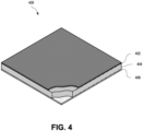
- FIG. 4 is an isometric cutaway diagram depicting the multiple layers of a section of can end stock 400 prepared according to the present disclosure.
- the can end stock 400 can include a layer of metal 404, such as aluminum (e.g., an aluminum alloy) surrounded by a laminated polymer film 402, and an optional layer of lacquer 406.
- the can end stock 400 can be the can end stock 110 of FIG. 1 .
- FIG. 5 is a flowchart depicting a process 500 for preparing can end stock according to embodiments of the present disclosure.
- the metal strip is provided.
- the metal strip can be an aluminum strip suitable for forming can end stock.
- the surface of the metal strip is optionally degreased (e.g., using an acid solution).
- the pretreatment coating is applied to the metal strip.
- the metal strip is laminated with a polymer film, e.g., a PET film.
- the laminated metal strip is annealed at an annealing temperature T A .
- the annealed metal strip is optionally quenched (e.g., in air).
- a wax coating can be optionally applied to one or both sides of the metal strip.
- FIG. 6 is a schematic diagram of a lamination system 614 according to certain aspects of the present disclosure.
- the lamination system 614 can be the lamination system 114 of FIG. 1 , or another lamination system. Certain elements depicted in FIG. 6 are shown at an exaggerated scale for demonstrative purposes only.
- the lamination system 614 can include a pair of rollers 652 through which a pretreated metal strip 604 may pass.
- the pretreated metal strip 604 can include a metal strip 602 that has been pretreated, such as by a pre-heating oven 112 of FIG. 1 .
- the pretreated metal strip 604 includes one or more conversion layers 603.
- a polymer film 624 When passing through the rollers 652, a polymer film 624 can be pressed against the pretreated metal strip 604 to produce a laminated metal strip 606.
- a single lamination system 614 can include additional sets of rollers to apply a second polymer film to an opposite side of the pre-heated metal strip 604 from the polymer film 624.
- rollers 652 can additionally apply a second polymer film to an opposite side of the pretreated metal strip 604 from the polymer film 624.
- the can end stock of the present disclosure e.g., the can end stock produced according to the described processes, advantageously exhibits a number of improved properties.
- the can end stock of the present disclosure exhibits low susceptibility to crazing. Said another way, the present disclosure described crazing-resistant can end stock.
- crazing refers to the formation and/or propagation of small cracks on or close to the surface of a protective layer (e.g., polymer film) on the metal strip, especially during a process for seaming, e.g., of a can end stock to a can body stock.
- the can end stock exhibits no visible crazing.
- the can end stock may exhibit no visible crazing before and/or after a seaming process.
- a 2% strain test can include assessing the susceptibility of the can end stock to crazing in response to tensile stress.
- the strain test may simulate a seaming process, where crazing is particularly problematic.
- the test can include stamping a sample of the can end stock (e.g., using an automatic press). The sample may be stamped into any shape suitable for a tensile strength test. The stamped samples are then stressed by applying a 2% strain with 10 N/mm 2 ⁇ s. Afterwards, the stressed samples are left, e.g., at room temperature, for 24 hours, during which time any crazing becomes visible.
- the 2% strain test may be carried out on an aged sample to maximize the susceptibility of the sample to crazing.
- the sample can end stock may be heated in an oven for several days (e.g., two days, three days, or four days) at a temperature 10 °C below the glass transition temperature of the polymer film.
- crazing may be visible on the can end stock, e.g., to the naked eye.
- crazing may be visible with the help of a light source.
- light may be shone on the sample from the direction of the camera and in a flat angle to the sample (e.g., parallel to the sample).
- the light source may shine visible light on the sample.
- the light source may shine UV light on the sample.
- the samples may be coated with a fluorescent marker.
- the samples may be covered with a fluorescent marker (e.g., FBP-914 from MET-L-CHEK (Santa Monica, CA)) for 10 minutes and rinsed with water. The fluorescence can greatly increase the visibility of crazing under a UV light.
- the can end stock exhibits no visible crazing after the strain test. In some embodiments, the can end stock exhibits no visible crazing under light after the strain test. In some embodiments, the can end stock exhibits no visible crazing under UV light after the strain test.
- the can end stock of the present disclosure exhibits improved adhesion. In some cases, for example, the can end stock of the present disclosure exhibits improved results on a 3% acetic acid test.
- a 3% acetic acid test can include assessing the resistance of a coating against diluted acidic media at approximately 100 °C for 30 minutes. The test can include cutting crosshatched markings into samples and placing the samples into a 3% acetic acid solution at approximately 100 °C for 30 minutes, after which the samples are removed and cooled down. After cooling, an additional set of cross cuts are performed on each sample, and adhesive tape is placed over the pre- and post-acid bath crosshatched regions and removing the tape steadily in 0.5 to 1 second at an angle of approximately 60°.
- the results of the test can be used to determine if the metal strip is acceptable or unacceptable given the desired specifications.
- the degree of delamination is observed and, to the extent delamination occurs, valued on a scale from 1 (minimal delamination) to 5.
- a sample passes the 3% acetic acid test if the sample demonstrates no or low delamination.
- the annealed, laminated can end stock disclosed herein obtain more favorable results in the 3% acetic acid tests (e.g., no or low delamination) than a standard, lacquered can end stock.
- the can end stock disclosed herein passes the 3% acetic acid test with low delamination.
- the annealed, laminated can end stock disclosed herein passes 3% acetic acid tests without delamination.
- the can end stock of the present disclosure exhibits reduced feathering.
- the can end stock of the present disclosure exhibits improved results on a standard feathering test.
- a standard feathering test can be conducted on a can end and may include immersing a can end in a bath of deionized water at approximately 75 °C for thirty minutes, rinsing the can end in cool deionized water to return the can end to room temperature, and then immediately opening the end tab of the can end. Feathering can be observed and measured on the scored panel or pour hole opening.
- a feathering test can be conducted on a flat sheet of metal, such as a flat sheet of can end stock.
- the feathering test can include immersing the sample in demineralized water at 80 °C for forty minutes, after which the sample is allowed to cool down to room temperature and the sample can be cut and a strip of metal can be separated by pulling the strip in a direction away from the cut.
- the amount of feathering can be measured, and the can end stock exhibiting a maximum amount of feathering less than 0.7 mm is said to pass the test.
- the can end stock described herein passes a standard feathering test.
- the can end stock exhibits a maximum amount of feathering of less than 0.7 mm, e.g., less than 0.6, less than 0.5 mm, less than 0.4 mm, less than 0.3 mm, or less than 0.2 mm. This amount of feathering may be located at certain indicative positions along the orifice of the opened can end. The amount of feathering of the film also depends on the cutting, forming and stamping tool design of the product.
- can end stock was prepared according to the disclosed methods. The samples were prepared using 0.208 mm thick AA 5182 aluminum alloy as the metal strip. Each of the samples tested is shown in Table 1. Each sample was pretreated, as indicated in Table 1, and can end stock was prepared by laminating a 12 ⁇ m polymer film to a first side (internal) and annealing at an annealing temperature.
- samples 4, 5, 7, 12, 15, 22, 23, and 24 were selected for additional crazing testing.
- the can end stock was subjected to a seaming process. Ends prepared from the sample can end stock were placed on empty can bodies (AA3104, 0.33 mm) and seamed with a laboratory seamer (Stiller DV10 PS-SD). To seam the can end to the body, the edge of the can end is curled and compressed around a rim of the body. After seaming, the can was stored for 24 hours. Afterward, the can end at the seam was covered in a fluorescence marker for 10 minutes, washed, and illuminated under UV light to observe any crazing. The results of this test are shown in Table 3.
- sample can end stock was subjected to a pack-test corrosion evaluation. Ends prepared from the sample can end stock were placed on can bodies (AA3104, 0.33 mm) and seamed with a laboratory seamer (Stiller DV10 PS-SD). The cans were filled with different beverages. Afterward, the cans were stored for 6 months upside down, such that the seam between the can end and body was covered by the beverage. The cans were evaluated for corrosion at 3 months and 6 months. No corrosion was found, as reported in Table 3.
- each sample was tested according to the 3% acetic acid test, described above, with the test for each sample being performed from the middle position of the sheet. To the extent delamination was observed, it was valued on a scale from 1 (minimal delamination) to 5.
- the above-described test was carried out by immersing the sample in demineralized water at 80 °C for forty minutes. Feathering was assessed at a middle position of the sheet, and each sample was assessed twice. The results of these tests are shown in Table 4. TABLE 4 Sample Acetic Acid Test Max. Feathering (mm) Cross-Cut Before Cross-Cross After First Run Second Run 1 Delam. 5 6.0 2.7 2 No delam. 1 0.6 0.6 3 No delam.
- any reference to a series of illustrations is to be understood as a reference to each of those illustrations disjunctively (e.g., "Illustrations 1-4" is to be understood as “Illustrations 1, 2, 3, or 4").
- Illustration 1 is a process for preparing a crazing-resistant can end stock, comprising: applying a pretreatment coating to a first side of a metal strip; laminating a polymer film to the first side of the metal strip to form a laminated metal strip, wherein the polymer film is adhered to at least a portion of the pretreatment coating; and annealing the laminated metal strip at an annealing temperature, wherein the annealing temperature is less than 250 °C.
- Illustration 2 is the process of any preceding or subsequent illustration, wherein the can end stock exhibits no visible crazing.
- Illustration 3 is the process of any preceding or subsequent illustration, wherein the first side of the metal strip corresponds to an interior-facing side of a can end formed from the metal strip.
- Illustration 4 is the process of any preceding or subsequent illustration, wherein the metal strip is an aluminum strip.
- Illustration 5 is the process of any preceding or subsequent illustration, wherein the polymer film comprises a polyethylene terephthalate film.
- Illustration 6 is the process of any preceding or subsequent illustration, wherein the pretreatment coating comprises a polymer or co-polymer.
- Illustration 7 is the process of any preceding or subsequent illustration, wherein the annealing temperatures is less than 230 °C.
- Illustration 8 is the process of any preceding or subsequent illustration, wherein the annealing temperature is greater than 150 °C.
- Illustration 9 is a can end stock product prepared according to the process of any preceding or subsequent illustration.
- Illustration 10 is the can end stock product of any preceding or subsequent illustration, wherein the first side of the metal strip corresponds to an exterior-facing side of the can end stock product.
- Illustration 11 is the can end stock product of any preceding or subsequent illustration, wherein the polymer film has a thickness less than 50 ⁇ m.
- Illustration 12 is a beverage can comprising a body piece and an end cap, wherein the end cap is formed from can end stock prepared according to the process of any preceding or subsequent illustration.
- Illustration 13 is a can end stock, comprising: a metal strip; a pretreatment composition; and a polymer film, wherein the can end stock exhibits no visible crazing.
- Illustration 14 is the can end stock of any preceding or subsequent illustration, wherein the can end stock exhibits no visible crazing within 24 hours after a strain test, wherein the strain test comprises application of a 2% strain with a 10 N/mm2 ⁇ s force.
- Illustration 15 is the can end stock of any preceding or subsequent illustration, wherein the can end stock exhibits no visible crazing under UV light within 24 hours after the strain test, wherein the strain test further comprises coating the samples with a fluorescent marker.
- Illustration 16 is the can end stock of any preceding or subsequent illustration, wherein the metal strip is an aluminum strip.
- Illustration 17 is the can end stock of any preceding or subsequent illustration, wherein the polymer film comprises a polyethylene terephthalate.
- Illustration 18 is the can end stock of any preceding or subsequent illustration, wherein the pretreatment composition is a polymer or co-polymer.
- Illustration 19 is the can end stock of any preceding or subsequent illustration, wherein the polymer film exhibits an FTIR absorbance peak intensity ratio (A/B) greater than 0.4, wherein A indicates a first absorbance peak at a wavenumber from 1330 cm 1 to 1350 cm 1 and B indicates a second absorbance peak at a wavenumber from 1400 cm 1 to 1420 cm-1.
- A/B FTIR absorbance peak intensity ratio
- Illustration 20 is the can end stock of any preceding or subsequent illustration, wherein the absorbance peak intensity ratio (A/B) is greater than 1.0.
- Illustration 21 is a system, comprising: a lamination system for accepting a metal strip and applying a polymer film to a first side of the metal strip; and an annealing furnace positioned downstream of the lamination system for accepting a laminated metal strip and heating the laminated metal strip at an annealing temperature, wherein the annealing temperature is less than 250 °C.
- Illustration 22 is the system of any preceding or subsequent illustration, wherein the metal strip is an aluminum strip.
- Illustration 23 is the system of any preceding or subsequent illustration, further comprising a pretreatment coating application system for applying a pretreatment coating to the metal strip, wherein the lamination system is configured to apply the polymer film to the pretreatment coating.
- Illustration 24 is the system of any preceding or subsequent illustration, wherein the lamination system is coupled to a supply of polyethylene terephthalate film.
- Illustration 25 is the system of any preceding or subsequent illustration, wherein the annealing temperature is less than 230 °C.
- Illustration 26 is the system of any preceding or subsequent illustration, wherein the annealing temperature is greater than 150 °C.
- Illustration 27 is a method for assessing the susceptibility of a can end stock to crazing, the method comprising: stamping a can end stock to produce a test sample; applying a strain to the test sample to produce a stressed sample; and observing the stressed sample for crazing.
- Illustration 28 is the method of any preceding or subsequent illustration, wherein applying a strain comprises applying a 2% strain with a 10 N/mm2 ⁇ s force.
- Illustration 29 is the method of any preceding or subsequent illustration, wherein observing the stressed sample comprises shining a light on the stressed sample.
- Illustration 30 is the method of any preceding or subsequent illustration, further comprising coating the test sample and/or the stressed sample with a fluorescent marker, and wherein observing the stressed sample comprises shining a UV light on the stressed sample.
Landscapes
- Physics & Mathematics (AREA)
- Thermal Sciences (AREA)
- Engineering & Computer Science (AREA)
- Mechanical Engineering (AREA)
- Laminated Bodies (AREA)
- Closures For Containers (AREA)
- Wrappers (AREA)
- Manufacture Of Macromolecular Shaped Articles (AREA)
Applications Claiming Priority (3)
| Application Number | Priority Date | Filing Date | Title |
|---|---|---|---|
| US202163178313P | 2021-04-22 | 2021-04-22 | |
| EP22724604.8A EP4326556B1 (fr) | 2021-04-22 | 2022-04-13 | Tôle pour extrémités de canettes résistante à la fissuration |
| PCT/US2022/071694 WO2022226469A1 (fr) | 2021-04-22 | 2022-04-13 | Tôle pour extrémités de canettes résistant à la fissuration |
Related Parent Applications (2)
| Application Number | Title | Priority Date | Filing Date |
|---|---|---|---|
| EP22724604.8A Division-Into EP4326556B1 (fr) | 2021-04-22 | 2022-04-13 | Tôle pour extrémités de canettes résistante à la fissuration |
| EP22724604.8A Division EP4326556B1 (fr) | 2021-04-22 | 2022-04-13 | Tôle pour extrémités de canettes résistante à la fissuration |
Publications (2)
| Publication Number | Publication Date |
|---|---|
| EP4520452A2 true EP4520452A2 (fr) | 2025-03-12 |
| EP4520452A3 EP4520452A3 (fr) | 2025-05-14 |
Family
ID=81749028
Family Applications (2)
| Application Number | Title | Priority Date | Filing Date |
|---|---|---|---|
| EP25152784.2A Pending EP4520452A3 (fr) | 2021-04-22 | 2022-04-13 | Matériau d'extrémité de canette résistant au craquelage |
| EP22724604.8A Active EP4326556B1 (fr) | 2021-04-22 | 2022-04-13 | Tôle pour extrémités de canettes résistante à la fissuration |
Family Applications After (1)
| Application Number | Title | Priority Date | Filing Date |
|---|---|---|---|
| EP22724604.8A Active EP4326556B1 (fr) | 2021-04-22 | 2022-04-13 | Tôle pour extrémités de canettes résistante à la fissuration |
Country Status (11)
| Country | Link |
|---|---|
| US (1) | US20240190108A1 (fr) |
| EP (2) | EP4520452A3 (fr) |
| JP (1) | JP2024514704A (fr) |
| KR (1) | KR102932780B1 (fr) |
| CN (1) | CN117177866A (fr) |
| BR (1) | BR112023021889A2 (fr) |
| CA (1) | CA3219758A1 (fr) |
| ES (1) | ES3020512T3 (fr) |
| MX (1) | MX2023012405A (fr) |
| PL (1) | PL4326556T3 (fr) |
| WO (1) | WO2022226469A1 (fr) |
Family Cites Families (11)
| Publication number | Priority date | Publication date | Assignee | Title |
|---|---|---|---|---|
| JPS6312445A (ja) * | 1986-06-24 | 1988-01-19 | 東洋製罐株式会社 | イ−ジイオ−プン蓋付缶体及びその製法 |
| GB9902299D0 (en) * | 1999-02-02 | 1999-03-24 | Du Pont | Polymeric film |
| JP2002337868A (ja) * | 2001-05-11 | 2002-11-27 | Mitsubishi Materials Corp | ラミネート缶蓋 |
| JP2004090968A (ja) * | 2002-08-30 | 2004-03-25 | Mitsubishi Materials Corp | ラミネート材及びラミネート缶蓋 |
| US10422040B2 (en) * | 2015-03-27 | 2019-09-24 | Toyo Seikan Group Holdings, Ltd. | Organic resin-covered surface-treated metal sheet |
| EP3439869B1 (fr) * | 2016-04-04 | 2023-09-06 | Tata Steel IJmuiden B.V. | Procédé de production d'une bande de métal à revêtement polymère et bande de métal à revêtement polymère ainsi produite |
| EP3455069B1 (fr) * | 2016-05-10 | 2025-02-26 | Novelis Inc. | Procédé et dispotiif pour laminer une matière première en extrémité de canette, avec recuit à température élevée |
| FR3051395B1 (fr) * | 2016-05-20 | 2018-05-11 | Constellium Neuf-Brisach | Bande metalloplastique pour emballage alimentaire rigide et procede de fabrication |
| WO2018025057A1 (fr) * | 2016-08-05 | 2018-02-08 | Toray Films Europe | Stratifié constitué d'un film de polyester multicouche et d'une feuille d'aluminium, procédé de fabrication dudit stratifié, et extrémités de boîtes de boisson fabriquées à partir dudit stratifié |
| US10836150B2 (en) * | 2017-03-30 | 2020-11-17 | Novelis Inc. | Surface roughening of polymer films |
| CA3124972A1 (fr) * | 2019-01-02 | 2020-07-09 | Novelis Inc. | Systemes et procedes de stratification de tole pour extremites de boites metalliques |
-
2022
- 2022-04-13 ES ES22724604T patent/ES3020512T3/es active Active
- 2022-04-13 MX MX2023012405A patent/MX2023012405A/es unknown
- 2022-04-13 US US18/556,169 patent/US20240190108A1/en active Pending
- 2022-04-13 EP EP25152784.2A patent/EP4520452A3/fr active Pending
- 2022-04-13 CA CA3219758A patent/CA3219758A1/fr active Pending
- 2022-04-13 WO PCT/US2022/071694 patent/WO2022226469A1/fr not_active Ceased
- 2022-04-13 JP JP2023564640A patent/JP2024514704A/ja active Pending
- 2022-04-13 EP EP22724604.8A patent/EP4326556B1/fr active Active
- 2022-04-13 CN CN202280029882.7A patent/CN117177866A/zh active Pending
- 2022-04-13 PL PL22724604.8T patent/PL4326556T3/pl unknown
- 2022-04-13 KR KR1020237035818A patent/KR102932780B1/ko active Active
- 2022-04-13 BR BR112023021889A patent/BR112023021889A2/pt unknown
Also Published As
| Publication number | Publication date |
|---|---|
| CA3219758A1 (fr) | 2022-10-27 |
| PL4326556T3 (pl) | 2025-04-28 |
| US20240190108A1 (en) | 2024-06-13 |
| MX2023012405A (es) | 2024-01-04 |
| EP4326556B1 (fr) | 2025-03-05 |
| WO2022226469A1 (fr) | 2022-10-27 |
| ES3020512T3 (en) | 2025-05-22 |
| KR20230160861A (ko) | 2023-11-24 |
| EP4520452A3 (fr) | 2025-05-14 |
| BR112023021889A2 (pt) | 2023-12-19 |
| KR102932780B1 (ko) | 2026-03-05 |
| JP2024514704A (ja) | 2024-04-02 |
| CN117177866A (zh) | 2023-12-05 |
| EP4326556A1 (fr) | 2024-02-28 |
Similar Documents
| Publication | Publication Date | Title |
|---|---|---|
| US12247271B2 (en) | Age-hardenable and highly formable aluminum alloys and methods of making the same | |
| US11826985B2 (en) | Systems and methods for laminating can end stock | |
| CA3061497A1 (fr) | Produits en alliage d'aluminium plaque | |
| EP4407068A2 (fr) | Alliages d'aluminium et alliages d'aluminium revêtus présentant une résistance élevée à la corrosion et leurs procédés de fabrication | |
| EP4520452A2 (fr) | Matériau d'extrémité de canette résistant au craquelage | |
| AU2018244458B2 (en) | Surface roughening of polymer films | |
| US20240181750A1 (en) | Laminated can end stock | |
| US20250187307A1 (en) | Aluminum alloy products with hot-melt lamination coatings for electrical insulation |
Legal Events
| Date | Code | Title | Description |
|---|---|---|---|
| PUAI | Public reference made under article 153(3) epc to a published international application that has entered the european phase |
Free format text: ORIGINAL CODE: 0009012 |
|
| STAA | Information on the status of an ep patent application or granted ep patent |
Free format text: STATUS: REQUEST FOR EXAMINATION WAS MADE |
|
| 17P | Request for examination filed |
Effective date: 20250120 |
|
| AC | Divisional application: reference to earlier application |
Ref document number: 4326556 Country of ref document: EP Kind code of ref document: P |
|
| AK | Designated contracting states |
Kind code of ref document: A2 Designated state(s): AL AT BE BG CH CY CZ DE DK EE ES FI FR GB GR HR HU IE IS IT LI LT LU LV MC MK MT NL NO PL PT RO RS SE SI SK SM TR |
|
| REG | Reference to a national code |
Ref country code: DE Ref legal event code: R079 Free format text: PREVIOUS MAIN CLASS: B21D0051260000 Ipc: B65D0025140000 |
|
| PUAL | Search report despatched |
Free format text: ORIGINAL CODE: 0009013 |
|
| AK | Designated contracting states |
Kind code of ref document: A3 Designated state(s): AL AT BE BG CH CY CZ DE DK EE ES FI FR GB GR HR HU IE IS IT LI LT LU LV MC MK MT NL NO PL PT RO RS SE SI SK SM TR |
|
| RIC1 | Information provided on ipc code assigned before grant |
Ipc: B32B 38/00 20060101ALI20250407BHEP Ipc: B65D 25/14 20060101AFI20250407BHEP |
|
| STAA | Information on the status of an ep patent application or granted ep patent |
Free format text: STATUS: EXAMINATION IS IN PROGRESS |
|
| 17Q | First examination report despatched |
Effective date: 20251217 |