EP4520473A1 - Mehrstufige bearbeitung eines werkstücks - Google Patents
Mehrstufige bearbeitung eines werkstücks Download PDFInfo
- Publication number
- EP4520473A1 EP4520473A1 EP24196296.8A EP24196296A EP4520473A1 EP 4520473 A1 EP4520473 A1 EP 4520473A1 EP 24196296 A EP24196296 A EP 24196296A EP 4520473 A1 EP4520473 A1 EP 4520473A1
- Authority
- EP
- European Patent Office
- Prior art keywords
- aperture
- workpiece
- manufacturing
- machining
- waterjet
- Prior art date
- Legal status (The legal status is an assumption and is not a legal conclusion. Google has not performed a legal analysis and makes no representation as to the accuracy of the status listed.)
- Pending
Links
Images




Classifications
-
- B—PERFORMING OPERATIONS; TRANSPORTING
- B23—MACHINE TOOLS; METAL-WORKING NOT OTHERWISE PROVIDED FOR
- B23P—METAL-WORKING NOT OTHERWISE PROVIDED FOR; COMBINED OPERATIONS; UNIVERSAL MACHINE TOOLS
- B23P15/00—Making specific metal objects by operations not covered by a single other subclass or a group in this subclass
- B23P15/02—Making specific metal objects by operations not covered by a single other subclass or a group in this subclass turbine or like blades from one piece
-
- B—PERFORMING OPERATIONS; TRANSPORTING
- B23—MACHINE TOOLS; METAL-WORKING NOT OTHERWISE PROVIDED FOR
- B23K—SOLDERING OR UNSOLDERING; WELDING; CLADDING OR PLATING BY SOLDERING OR WELDING; CUTTING BY APPLYING HEAT LOCALLY, e.g. FLAME CUTTING; WORKING BY LASER BEAM
- B23K26/00—Working by laser beam, e.g. welding, cutting or boring
- B23K26/36—Removing material
- B23K26/38—Removing material by boring or cutting
- B23K26/382—Removing material by boring or cutting by boring
-
- B—PERFORMING OPERATIONS; TRANSPORTING
- B23—MACHINE TOOLS; METAL-WORKING NOT OTHERWISE PROVIDED FOR
- B23K—SOLDERING OR UNSOLDERING; WELDING; CLADDING OR PLATING BY SOLDERING OR WELDING; CUTTING BY APPLYING HEAT LOCALLY, e.g. FLAME CUTTING; WORKING BY LASER BEAM
- B23K26/00—Working by laser beam, e.g. welding, cutting or boring
- B23K26/14—Working by laser beam, e.g. welding, cutting or boring using a fluid stream, e.g. a jet of gas, in conjunction with the laser beam; Nozzles therefor
- B23K26/146—Working by laser beam, e.g. welding, cutting or boring using a fluid stream, e.g. a jet of gas, in conjunction with the laser beam; Nozzles therefor the fluid stream containing a liquid
-
- B—PERFORMING OPERATIONS; TRANSPORTING
- B23—MACHINE TOOLS; METAL-WORKING NOT OTHERWISE PROVIDED FOR
- B23P—METAL-WORKING NOT OTHERWISE PROVIDED FOR; COMBINED OPERATIONS; UNIVERSAL MACHINE TOOLS
- B23P6/00—Restoring or reconditioning objects
- B23P6/002—Repairing turbine components, e.g. moving or stationary blades, rotors
-
- B—PERFORMING OPERATIONS; TRANSPORTING
- B23—MACHINE TOOLS; METAL-WORKING NOT OTHERWISE PROVIDED FOR
- B23K—SOLDERING OR UNSOLDERING; WELDING; CLADDING OR PLATING BY SOLDERING OR WELDING; CUTTING BY APPLYING HEAT LOCALLY, e.g. FLAME CUTTING; WORKING BY LASER BEAM
- B23K26/00—Working by laser beam, e.g. welding, cutting or boring
- B23K26/36—Removing material
- B23K26/38—Removing material by boring or cutting
- B23K26/382—Removing material by boring or cutting by boring
- B23K26/389—Removing material by boring or cutting by boring of fluid openings, e.g. nozzles, jets
-
- B—PERFORMING OPERATIONS; TRANSPORTING
- B23—MACHINE TOOLS; METAL-WORKING NOT OTHERWISE PROVIDED FOR
- B23P—METAL-WORKING NOT OTHERWISE PROVIDED FOR; COMBINED OPERATIONS; UNIVERSAL MACHINE TOOLS
- B23P2700/00—Indexing scheme relating to the articles being treated, e.g. manufactured, repaired, assembled, connected or other operations covered in the subgroups
- B23P2700/06—Cooling passages of turbine components, e.g. unblocking or preventing blocking of cooling passages of turbine components
-
- F—MECHANICAL ENGINEERING; LIGHTING; HEATING; WEAPONS; BLASTING
- F01—MACHINES OR ENGINES IN GENERAL; ENGINE PLANTS IN GENERAL; STEAM ENGINES
- F01D—NON-POSITIVE DISPLACEMENT MACHINES OR ENGINES, e.g. STEAM TURBINES
- F01D5/00—Blades; Blade-carrying members; Heating, heat-insulating, cooling or antivibration means on the blades or the members
- F01D5/12—Blades
- F01D5/14—Form or construction
- F01D5/18—Hollow blades, i.e. blades with cooling or heating channels or cavities; Heating, heat-insulating or cooling means on blades
- F01D5/186—Film cooling
Definitions
- This disclosure relates generally to machining and, more particularly, to machining a workpiece with a waterjet.
- a gas turbine engine includes various fluid cooled components such as turbine blades and turbine vanes.
- Such fluid cooled components may include one or more cooling apertures extending through a sidewall of the respective component.
- Various methods are known in the art for forming cooling apertures, including methods which machine the cooling apertures with an energy beam or a waterj et. While these known cooling aperture formation methods have various benefits, there is still room in the art form improvement. For example, where the sidewall includes a ceramic coating over a metal substrate, forming a cooling aperture through the sidewall using laser drilling (or another high energy process) may cause spallation and/or delamination of the ceramic coating.
- While using a waterjet to form the cooling aperture in the ceramic coating may reduce or prevent spallation and/or delamination of the ceramic coating, excessive coating material may be removed by the waterjet, particularly where the waterjet initially impinges against an outer surface of the ceramic coating at an acute angle. This excessive removal of the coating material may lead to formation of an oversized and/or irregular cooling aperture outlet.
- the waterjet may also skip along the ceramic coating and form another aperture in the outer surface.
- a manufacturing method is provided. During this manufacturing method, a workpiece is provided that includes a face surface and a back surface. A first aperture is machined into the workpiece using an energy beam. The first aperture projects partially into the workpiece from the face surface to an end of the first aperture. A waterjet is directed into the first aperture to machine a second aperture into the workpiece. The second aperture extends from the end of the first aperture to the back surface.
- a workpiece is provided with a face surface and a back surface.
- the workpiece extends between the face surface and the back surface.
- the workpiece is machined with an energy beam to form a blind aperture.
- the blind aperture projects into the workpiece from the face surface.
- the workpiece is machined with a waterjet to extend the blind aperture to the back surface and form a cooling aperture.
- the cooling aperture extends from an inlet in the back surface to an outlet in the face surface.
- a workpiece with a face surface and a back surface is provided.
- the workpiece includes a substrate and a coating over the substrate.
- the substrate forms the back surface.
- the coating forms the face surface.
- a pilot aperture is formed into or through the coating. The pilot aperture is extended through a remainder of the workpiece to the back surface using a waterjet.
- the blind aperture may project into the workpiece to an end surface.
- a centerline of the waterjet may be angularly offset from the end surface by an angle when the machining of the workpiece with the waterjet begins.
- the angle may be between eighty-five degrees and ninety degrees.
- the workpiece may include a substrate and a coating over the substrate.
- the blind aperture may project through the coating to or into the substrate.
- the energy beam may be a pulsed laser beam.
- the energy beam may be a laser beam generated by a percussion laser machining device.
- the energy beam may be a laser beam generated by an ablation laser machining device.
- the workpiece may include a substrate and a coating over the substrate.
- the first aperture may project from the face surface and partially into or through the coating.
- the coating may be configured from or otherwise include a ceramic material.
- the coating may be configured from or otherwise include a metal material.
- a centerline of the first aperture may be angularly offset from the face surface by an acute angle.
- the energy beam may extend along a centerline when machining the first aperture.
- the waterjet may extend along the centerline when machining the second aperture.
- a centerline of the waterjet may be perpendicular to the end of the first aperture formed by the energy beam when the waterjet is initially directed into the first aperture to begin machining the second aperture.
- the waterj et may enlarge the first aperture providing an enlarged first aperture during the machining of the second aperture.
- At least the enlarged first aperture and the second aperture may form a cooling aperture in the workpiece.
- the cooling aperture may extend from an inlet in the back surface to an outlet in the face surface.
- the waterjet may remove recast and/or thermally damaged material from the first aperture during the machining of the second aperture.
- a centerline of the second aperture may be angularly offset from the face surface by an acute angle.
- the waterj et may be formed by a mixture of water and media entrained in the water.
- the manufacturing method may also include forming a component of a turbine engine.
- the forming of the component may include the machining of the first aperture and the machining of the second aperture.
- a cooling hole may include the first aperture and the second aperture.
- the cooling hole may include a meter section and a diffuser section.
- An outlet of the diffuser section may be substantially formed by the machining of the first aperture with the energy beam.
- the present disclosure may include any one or more of the individual features disclosed above and/or below alone or in any combination thereof.
- the present disclosure includes methods for manufacturing a component such as a fluid cooled component of a gas turbine engine.
- the term “manufacturing” may describe a process for original manufacturing the component; e.g., creating a brand new component.
- the term “manufacturing” may also or alternatively describe a process for remanufacturing or otherwise repairing the component; e.g., restoring one or more features of a previously formed component to brand new condition, similar to brand new condition, better than brand new condition, etc.
- the component for example, may be repaired to fix one or more defects (e.g., cracks, wear and/or other damage) imparted during previous use of the component.
- the component may also or alternatively be repaired to fix one or more defects imparted during the initial formation of the component.
- the turbine engine may be described below as a turbofan turbine engine.
- the present disclosure is not limited to such an exemplary gas turbine engine.
- the turbine engine may alternatively be configured as a turbojet turbine engine, a turboprop turbine engine, a turboshaft turbine engine, a propfan turbine engine, a pusher fan turbine engine or an auxiliary power unit (APU) turbine engine.
- the turbine engine may be configured as a geared turbine engine or a direct drive turbine engine.
- the present disclosure is also not limited to aircraft applications.
- the turbine engine for example, may alternatively be configured as a ground-based industrial turbine engine for power generation, or any other type of turbine engine which utilizes fluid cooled components.
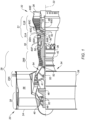
- FIG. 1 is a side cutaway illustration of the turbofan turbine engine 20.
- This turbine engine 20 extends along an axial centerline 22 between a forward, upstream airflow inlet 24 and an aft, downstream combustion products exhaust 26.
- the turbine engine 20 includes a fan section 28, a compressor section 29, a combustor section 30, a turbine section 31 and an exhaust section 32 (partially shown in FIG. 1 ).
- the compressor section 29 includes a low pressure compressor (LPC) section 29A and a high pressure compressor (HPC) section 29B.
- the turbine section 31 includes a high pressure turbine (HPT) section 31A and a low pressure turbine (LPT) section 31B.
- the engine sections 28-31B of FIG. 1 are arranged sequentially along the axial centerline 22 within an engine housing 34.
- This engine housing 34 includes an inner case 36 (e.g., a core case) and an outer case 38 (e.g., a fan case).
- the inner case 36 may house one or more of the engine sections 29A-31B; e.g., a core of the turbine engine 20.
- the outer case 38 may house at least the fan section 28.
- Each of the engine sections 28, 29A, 29B, 31A and 31B includes a respective bladed rotor 40-44.
- Each of these bladed rotors 40-44 includes a plurality of rotor blades arranged circumferentially around and connected to one or more respective rotor disks.
- the rotor blades may be formed integral with or mechanically fastened, welded, brazed and/or otherwise attached to the respective rotor disk(s).
- the fan rotor 40 is connected to a geartrain 46, for example, through a fan shaft 48.
- the geartrain 46 and the LPC rotor 41 are connected to and driven by the LPT rotor 44 through a low speed shaft 49.
- the HPC rotor 42 is connected to and driven by the HPT rotor 43 through a high speed shaft 50.
- the engine shafts 48-50 are rotatably supported by a plurality of bearings 52; e.g., rolling element and/or thrust bearings. Each of these bearings 52 is connected to the engine housing 34 by at least one stationary structure such as, for example, an annular support frame.
- This air is directed through the fan section 28 and into a core flowpath 54 and a bypass flowpath 56.
- the core flowpath 54 extends sequentially through the engine sections 29A-32; e.g., the engine core.
- the air within the core flowpath 54 may be referred to as "core air”.
- the bypass flowpath 56 extends through a bypass duct, which bypasses the engine core.
- the air within the bypass flowpath 56 may be referred to as "bypass air”.
- the core air is compressed by the LPC rotor 41 and the HPC rotor 42 and directed into a combustion chamber 58 of a combustor in the combustor section 30.
- Fuel is injected into the combustion chamber 58 and mixed with the compressed core air to provide a fuel-air mixture.
- This fuel air mixture is ignited and combustion products thereof flow through and sequentially cause the HPT rotor 43 and the LPT rotor 44 to rotate.
- the rotation of the HPT rotor 43 and the LPT rotor 44 respectively drive rotation of the HPC rotor 42 and the LPC rotor 41 and, thus, compression of the air received from a core airflow inlet.
- the rotation of the LPT rotor 44 also drives rotation of the fan rotor 40, which propels the bypass air through and out of the bypass flowpath 56.
- the propulsion of the bypass air may account for a majority of thrust generated by the turbine engine 20; e.g., more than seventy-five percent (75%) of engine thrust.
- the turbine engine 20 of the present disclosure is not limited to the foregoing exemplary thrust ratio.
- the turbine engine 20 includes a plurality of fluid cooled components (e.g., 60AH; generally referred to as "60") arranged within, for example, the combustor section 30, the turbine section 31 and/or the exhaust section 32.
- these fluid cooled components 60 include airfoils such as, but not limited to, a rotor blade airfoil (e.g., 60A, 60D) and a stator vane airfoil (e.g., 60B, 60C, 60H).
- fluid cooled components 60 include flowpath walls such as, but not limited to, a combustor liner (e.g., 60F), an exhaust duct liner (e.g., 60E), a shroud or other flowpath wall (e.g., 60G), a rotor blade platform, a stator vane platform, and the like.
- flowpath walls such as, but not limited to, a combustor liner (e.g., 60F), an exhaust duct liner (e.g., 60E), a shroud or other flowpath wall (e.g., 60G), a rotor blade platform, a stator vane platform, and the like.
- flowpath walls such as, but not limited to, a combustor liner (e.g., 60F), an exhaust duct liner (e.g., 60E), a shroud or other flowpath wall (e.g., 60G), a rotor blade platform, a stator vane platform, and the
- This cooling fluid volume 72 may be an internal volume formed within the fluid cooled component 60 where, for example, the component 60 is an airfoil. Alternatively, the cooling fluid volume 72 may be an external volume formed external to the fluid cooled component 60 where, for example, the component 60 is a flowpath wall.
- the component second surface 70 may be configured as an exterior, a hot side and/or a face surface of the fluid cooled component 60 and its component wall 62. The component second surface 70, for example, may at least partially form a peripheral boundary of a portion of, for example, the core flowpath 54 along the component wall 62. The component second surface 70 may thereby be subject to relative hot fluid (e.g., combustion products) flowing through the core flowpath 54 within, for example, one of the engine sections 30-32 of FIG. 1 .
- relative hot fluid e.g., combustion products
- the component wall 62 of FIG. 3 includes a component substrate 74 and a coating system 76.
- the coating system 76 may include one or more external component coatings 78 and 80 over the component substrate 74.
- the component substrate 74 at least partially or completely forms and carries the component first surface 68.
- the component substrate 74 has a thickness 82 that extends vertically (e.g., along the z-axis) between and to the component first surface 68 and a second surface 84 of the component substrate 74.
- the substrate second surface 84 may be configured as an exterior surface of the component substrate 74 prior to being (e.g., partially or completely) covered by the coating system 76 and its one or more component coatings 78 and 80.
- the substrate thickness 82 may be greater than one-half (1/2) of the wall thickness 66.
- the substrate thickness 82 for example, may be between two-third (2/3) and four-fifths (4/5) of the wall thickness 66. In other embodiments, however, it is contemplated the substrate thickness 82 may be greater than four-fifths (4/5) of the wall thickness 66 or less than one-half (1/2) of the wall thickness 66.
- the inner coating 78 may be formed from a single layer of the inner coating material.
- the inner coating 78 may alternatively be formed from a plurality of layers of the inner coating material, where the inner coating material within each of those inner coating layers may be the same as one another or different from one another.
- the outer coating 80 may be configured as a protective coating for the component substrate 74 and, more generally, the fluid cooled component 60.
- the outer coating 80 may be configured as a thermal barrier layer and/or an environmental layer.
- the outer coating 80 at least partially or completely forms and carries the component second surface 70.
- the outer coating 80 of FIG. 3 is bonded (e.g., directly) to a second (e.g., exterior) surface 88 of the inner coating 78.
- the outer coating 80 at least partially or completely covers the inner coating second surface 88 as well as the underlying substrate second surface 84 (e.g., along the x-y plane of FIG. 2 ).
- the outer coating 80 has a thickness 90 that extends vertically (e.g., along the z-axis) between and to the inner coating 78 and the component second surface 70.
- This outer coating thickness 90 may be less than one-half (1/2) of the wall thickness 66.
- the outer coating thickness 90 for example, may be between one-third (1/3) and one-eighth (1/8) of the wall thickness 66. In other embodiments, however, it is contemplated the outer coating thickness 90 may be greater than one-half (1/2) of the wall thickness 66 or less than one-eighth (1/8) of the wall thickness 66.
- the outer coating 80 is constructed from outer coating material.
- This outer coating material may be a non-electrically conductive material.
- the outer coating material may be or otherwise include ceramic. Examples of the ceramic include, but are not limited to, yttria stabilized zirconia (YSZ) and gadolinium zirconate (GdZ).
- YSZ yttria stabilized zirconia
- GdZ gadolinium zirconate
- the outer coating material of the present disclosure is not limited to non-electrically conductive materials. In other embodiments, for example, the outer coating material may be an electrically conductive material; e.g., metal.
- the outer coating 80 may be formed from a single layer of the outer coating material.
- the outer coating 80 may alternatively be formed from a plurality of layers of the outer coating material, where the outer coating material within each of those outer coating layers may be the same as one another or different from one another.
- the outer coating 80 may include a thin interior layer of the YSZ and a thicker exterior later of the GdZ.
- Each of the cooling apertures 64 extends along a longitudinal centerline 92 of the respective cooling aperture 64 between and to an inlet 94 into the respective cooling aperture 64 and an outlet 96 from the respective cooling aperture 64.
- This aperture centerline 92 may have a straight line geometry (e.g., in the x-y plane, in an x-z plane and/or in a y-z plane) from the cooling aperture inlet 94, through the component wall 62, to the cooling aperture outlet 96.
- the aperture centerline 92 of FIG. 3 is angularly offset from the component first surface 68 by a first angle 98
- the aperture centerline 92 is angularly offset from the component second surface 70 by a second angle 100.
- the first angle 98 and the second angle 100 are each non-zero acute angles - greater than zero degrees (0°) and less than ninety degrees (90°).
- the first angle 98 and the second angle 100 may each be between ten degrees (10°) and eighty degrees (80°); e.g., between twenty degrees (20°) and forty degrees (40°), or between forty degrees (40°) and sixty degrees (60°).
- the first angle 98 and/or the second angle 100 may each be greater than eighty degrees (80°); e.g., a ninety degree (90°) right angle.
- the cooling aperture inlet 94 of FIG. 3 is located in the component first surface 68.
- the cooling aperture inlet 94 thereby fluidly couples its respective cooling aperture 64 with the cooling fluid volume 72 along the component first surface 68.
- the cooling aperture inlet 94 has a cross-sectional geometry (e.g., shape and dimensions) when viewed in a reference plane parallel with the component first surface 68 at the respective cooling aperture inlet 94.
- This inlet geometry may have a curved shape; e.g., an oval shape, a circular shape, etc.
- the cooling aperture outlet 96 of FIG. 3 is located in the component second surface 70.
- the cooling aperture outlet 96 thereby fluidly couples its respective cooling aperture 64 with the core flowpath 54 along the component second surface 70.
- the cooling aperture outlet 96 has a cross-sectional geometry (e.g., shape and dimensions) when viewed in a reference plane parallel with the component second surface 70 at the respective cooling aperture outlet 96.
- This outlet geometry may have a curved shape (e.g., an oval shape, a circular shape, or an amorphous curved shape), a polygonal shape (e.g., an elongated rectangular shape, a (e.g., equilateral) trapezoidal shape, or an amorphous polygonal shape), a combined curved-polygonal shape, or any other regular or irregular shape.
- a curved shape e.g., an oval shape, a circular shape, or an amorphous curved shape
- a polygonal shape e.g., an elongated rectangular shape, a (e.g., equilateral) trapezoidal shape, or an amorphous polygonal shape
- a combined curved-polygonal shape e.g., a combined curved-polygonal shape, or any other regular or irregular shape.
- the outlet geometry may be exactly or substantially the same as the inlet geometry.
- the shape of the cooling aperture outlet 96 may be exactly or substantially the same as the shape of the cooling aperture inlet 94.
- Dimensions (e.g., a width) of the cooling aperture outlet 96 may also be exactly or substantially equal to dimensions (e.g., a width) of the cooling aperture inlet 94.
- one or more of the cooling apertures 64 may each be configured with a metering section 102 at its cooling aperture inlet 94 and a diffuser section 104 at its cooling aperture outlet 96.
- the dimensions of the cooling aperture outlet 96 are different (e.g., greater) than the dimensions of the cooling aperture inlet 94.
- the shape of the cooling aperture outlet 96 may also be different than the shape of the cooling aperture inlet 94.
- the metering section 102 may have a uniform (e.g., constant) cross-sectional geometry as the respective cooling aperture 64 extends from its cooling aperture inlet 94 to its diffuser section 104.
- the diffuser section 104 may have a cross-sectional geometry that changes (e.g., expands) as the respective cooling aperture 64 extends from its metering section 102 to its cooling aperture outlet 96.
- the aperture centerline 92 of FIG. 4 has a non-straight line (e.g., bent, curved, etc.) geometry, for example, at an intersection between the metering section 102 and the diffuser section 104.
- the first angle 98 of FIG. 4 is thereby different (e.g., greater) than the second angle 100.
- the cooling apertures 64 may be described below as shown in FIG. 3 ; e.g., without diffuser sections.
- FIG. 5 is a flow diagram of a method 500 for manufacturing a component.
- the manufacturing method 500 is described below with reference to original manufacturing the fluid cooled component 60 of FIG. 3 .
- the manufacturing method 500 of the present disclosure is not limited to manufacturing such an exemplary fluid cooled component nor to manufacturing fluid cooled components in general.
- the manufacturing method 500 may alternatively be performed to manufacture the fluid cooled component 60 of FIG. 4 or a component with various other machined features; e.g., cooling apertures or other through-holes, etc.
- the manufacturing method 500 may also be performed for remanufacturing and/or otherwise repairing a previously originally manufactured component.
- a workpiece 106 is provided.
- This workpiece 106 may be a preform of the fluid cooled component 60 being manufactured.
- the workpiece 106 may generally have the same configuration (e.g., construction, shape, size, etc.) as that of the fluid cooled component 60 being manufactured.
- the workpiece 106 of FIG. 6 in particular, includes the component substrate 74 and the coating system 76 applied over the component substrate 74.
- the workpiece 106 of FIG. 6 does not include any (or at least one or more) of the cooling apertures 64 which is/are to be formed during the manufacturing method 500.
- the present disclosure is not limited to such an exemplary workpiece configuration.
- the workpiece 106 may alternatively omit the outer coating 80 or the entire coating system 76, where the cooling apertures 64 are solely formed in the component substrate 74 and/or the outer coating 80 or the entire coating system 76 are applied subsequent to formation of the aperture(s) 64 in the component substrate 74.
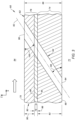
- the workpiece 106 is machined to form a first aperture 108 in the workpiece 106.
- a controller 110 may signal an energy beam machining device 112 to generate an energy beam 114 such as a laser beam or an electron beam.
- the controller 110 may further signal the energy beam machining device 112 to direct the energy beam 114 to a target location on the workpiece 106.
- the energy beam 114 is a laser beam
- the laser beam may be directed to the target location by adjusting galvo mirrors.
- the energy beam 114 is an electron beam
- the electron beam may be directed to the target location using magnetic manipulation.
- the energy beam 114 machines away material of the workpiece 106 (e.g., outer coating material, inner coating material and/or substrate material depending upon a depth of the first aperture 108; see FIGS. 7A-C ) to form the first aperture 108.
- the energy beam 114 may be directed onto the workpiece 106 as a pulsed energy beam (e.g., with pulses) or a constant energy beam (e.g., without pulses).
- the energy beam machining device 112 may be configured as or otherwise include percussion laser machining device or an ablation laser machining device.
- the energy beam machining device 112 may include a Nd:YAG laser, a fiber laser percussion drilling laser, a Yb disk laser, or an ultrashort pulse laser (e.g., a nano-, pico-, or femto- laser system).
- the laser beam (energy beam 114) may have various wavelengths such as, but not limited to, 1.07 microns, 0.535 microns, etc.
- a pulse width of the laser beam may be on the order of millisecond, nano-second, down to pico-second or femto-second.
- the use of different pulse widths may decrease the thermal interaction with the workpiece 106 and therefore reduce or eliminate recast and/or heat effected zone (HAZ) damage in the initial removal of material.
- HZ heat effected zone
- This first aperture 108 is configured as a pilot aperture for machining the to-be-formed cooling aperture 64.
- the first aperture 108 of FIG. 7A is a blind aperture.
- This first aperture 108 projects longitudinally a centerline 116 of the first aperture 108 into the workpiece 106 from a face surface 118 of the workpiece 106 (e.g., the component second surface 70) to a longitudinal distal end of the first aperture 108.
- the first aperture centerline 116 may be parallel (e.g., coaxial) with or close to parallel with (e.g., within +/- 5° to 10° of) the centerline 92 of the to-be-formed cooling aperture 64.
- the first aperture centerline 116 may thereby be angularly offset from the workpiece face surface 118 by a non-zero acute angle; e.g., equal to or within +/- 5° to 10° of the second angle 100 (see FIG. 3 ).
- the aperture distal end of FIG. 7A is formed by an internal surface 120 of the workpiece 106.
- the internal surface 120 is angularly offset from the first aperture centerline 116 by a surface offset angle 122.
- This surface offset angle 122 may be equal to ninety degrees (90°) - a right angle.
- the surface offset angle 122 may be within five degrees (5°) or ten degrees (10°) of a right angle (e.g., 80-85°) - a steep acute angle.
- the first aperture 108 may project partially into and/or through the coating system 76 and its coatings 78 and/or 80.
- the first aperture 108 of FIG. 7A extends in the coating system 76 and its coatings 78 and 80 to the component substrate 74.
- an edge of the internal surface 120 is adjacent the substrate second surface 84.
- the internal surface 120 is formed by at least (or only) the inner coating material and the outer coating material; however, it is contemplated the internal surface 120 may alternatively be formed independent of the inner coating material (see dashed line 120').
- the first aperture 108 extends partially into the component substrate 74. With the arrangement of FIG.
- the internal surface 120 is formed by at least (or only) the substrate material, the inner coating material and the outer coating material; however, it is contemplated the internal surface 120 may alternatively be formed independent of the outer coating material (see dashed line 120").
- the first aperture 108 extends completely into the component substrate 74. With the arrangement of FIG. 7C , the internal surface 120 is formed (e.g., completely) by the substrate material.
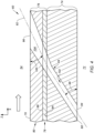
- the workpiece 106 is further machined to form a second aperture 124 in the workpiece 106.
- the controller 110 may signal a waterjet machining device 126 to direct a waterjet 128 into the first aperture 108 to a target location on the internal surface 120.
- the waterjet 128 is a highly pressurized and concentrated stream (e.g., jet) of fluid, where the fluid may be a mixture of water and media (e.g., grit, abrasive material) entrained in the water, or pure water.
- the waterjet 128 machines away material of the workpiece 106 (e.g., outer coating material, inner coating material and/or substrate material depending upon the depth of the first aperture 108; see FIGS. 7A-C ) to form the second aperture 124.
- the waterjet 128 may remove recast material and/or thermally damaged material along a side of the first aperture 108.
- the waterjet 128 may also smooth out, enlarge and/or further define a geometry (e.g., shape and/or dimensions) the first aperture 108 to provide a modified (e.g., enlarged) first aperture 108'.
- This enlargement / further defining of the first aperture 108 may be performed directly by the waterjet 128.
- the enlargement / further defining may also or alternatively be performed indirectly by a fluid backflow out of the first aperture 108 following impingement of the waterjet 128 at a target location to form a respective portion of the second aperture 124.
- the waterj et 128 is directed into / through the first aperture 108 for the machining of the second aperture 124 along a trajectory.
- This trajectory is selected such that a centerline 130 of the waterjet 128 is parallel (e.g., coaxial) with or close to parallel with (e.g., within +/- 5° to 10° of) the centerline 92 of the to-be-formed cooling aperture 64.
- the waterjet centerline 130 is also angularly offset from the internal surface 120 by a waterjet offset angle 132.
- This waterjet offset angle 132 may be equal to ninety degrees (90°) - a right angle.
- the waterjet offset angle 132 may be within five degrees (5°) or ten degrees (10°) of a right angle (e.g., 80-85°) - a steep acute angle.
- the waterjet 128 may machine away the material without, for example, any or substantial skipping off of the internal surface 120.
- the skipping off of fluid from a fluid jet may lead to removal of too much material from the workpiece 106 (e.g., formation of a cone-shaped opening at the workpiece face surface 118) and/or debonding, cracking and/or spallation of the coating system 76 and, in particular, the outer coating 80.
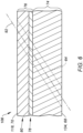
- the formation of the second aperture 124 builds upon (e.g., extends) the formation of the first aperture 108 to provide the respective cooling aperture 64.
- the second aperture 124 of FIG. 8 projects longitudinally along the aperture centerline 92 from the first aperture 108, through a remainder of a thickness of the workpiece 106, to a back surface 134 of the workpiece 106 (e.g., the component first surface 68).
- at least (or only) the second aperture 124 and the modified first aperture 108' may collectively form the respective cooling aperture 64.
- the modified first aperture 108' forms the cooling aperture outlet 96 in the workpiece face surface 118.
- the second aperture 124 forms the cooling aperture inlet 94 in the workpiece back surface 134.
- step 508 the method steps 504 and 506 may be repeated one or more times to form one or more additional cooling apertures 64 in the workpiece 106.
- the machined workpiece 106 may form the (e.g., complete / fully formed) fluid cooled component 60.
- the formation of the multiple cooling apertures 64 may be performed in stages. For example, each first aperture 108 for a set of to-be-formed cooling apertures 64 may be formed prior to forming the second apertures 124 for that cooling aperture set.
- the workpiece 106 may be arranged at a first location; e.g., within a machining chamber for the energy beam machining device 112.
- the workpiece 106 may be arranged at a second location; e.g., within a machining chamber for the waterjet machining device 126.
- the energy beam machining device 112 and the waterjet machining device 126 may be collocated such that the workpiece 106 may remain stationary (e.g., fixtured) at a common (the same) location; e.g., within a common process chamber.
- the manufacturing method 500 of the present disclosure is not limited to such exemplary machining device arrangements nor to a staged machining approach.
Landscapes
- Engineering & Computer Science (AREA)
- Mechanical Engineering (AREA)
- Physics & Mathematics (AREA)
- Optics & Photonics (AREA)
- Plasma & Fusion (AREA)
- Turbine Rotor Nozzle Sealing (AREA)
Applications Claiming Priority (1)
| Application Number | Priority Date | Filing Date | Title |
|---|---|---|---|
| US18/238,214 US20250065444A1 (en) | 2023-08-25 | 2023-08-25 | Multi-process machining of a workpiece |
Publications (1)
| Publication Number | Publication Date |
|---|---|
| EP4520473A1 true EP4520473A1 (de) | 2025-03-12 |
Family
ID=92538410
Family Applications (1)
| Application Number | Title | Priority Date | Filing Date |
|---|---|---|---|
| EP24196296.8A Pending EP4520473A1 (de) | 2023-08-25 | 2024-08-23 | Mehrstufige bearbeitung eines werkstücks |
Country Status (2)
| Country | Link |
|---|---|
| US (1) | US20250065444A1 (de) |
| EP (1) | EP4520473A1 (de) |
Families Citing this family (1)
| Publication number | Priority date | Publication date | Assignee | Title |
|---|---|---|---|---|
| JP2025117176A (ja) * | 2024-01-30 | 2025-08-12 | 本田技研工業株式会社 | 壁部材及びその製造方法 |
Citations (4)
| Publication number | Priority date | Publication date | Assignee | Title |
|---|---|---|---|---|
| US6329015B1 (en) * | 2000-05-23 | 2001-12-11 | General Electric Company | Method for forming shaped holes |
| US20130206739A1 (en) * | 2012-02-15 | 2013-08-15 | United Technologies Corporation | Manufacturing methods for multi-lobed cooling holes |
| US11542831B1 (en) * | 2021-08-13 | 2023-01-03 | Raytheon Technologies Corporation | Energy beam positioning during formation of a cooling aperture |
| US20230070114A1 (en) * | 2021-09-03 | 2023-03-09 | Raytheon Technologies Corporation | Multi-step method for machining blind ope1ning in ceramic component |
-
2023
- 2023-08-25 US US18/238,214 patent/US20250065444A1/en active Pending
-
2024
- 2024-08-23 EP EP24196296.8A patent/EP4520473A1/de active Pending
Patent Citations (4)
| Publication number | Priority date | Publication date | Assignee | Title |
|---|---|---|---|---|
| US6329015B1 (en) * | 2000-05-23 | 2001-12-11 | General Electric Company | Method for forming shaped holes |
| US20130206739A1 (en) * | 2012-02-15 | 2013-08-15 | United Technologies Corporation | Manufacturing methods for multi-lobed cooling holes |
| US11542831B1 (en) * | 2021-08-13 | 2023-01-03 | Raytheon Technologies Corporation | Energy beam positioning during formation of a cooling aperture |
| US20230070114A1 (en) * | 2021-09-03 | 2023-03-09 | Raytheon Technologies Corporation | Multi-step method for machining blind ope1ning in ceramic component |
Non-Patent Citations (1)
| Title |
|---|
| MARIMUTHU SUNDAR ET AL: "Water-jet guided laser drilling of thermal barrier coated aerospace alloy", THE INTERNATIONAL JOURNAL OF ADVANCED MANUFACTURING TECHNOLOGY, vol. 113, no. 1-2, 21 January 2021 (2021-01-21), pages 177 - 191, XP037374194, ISSN: 0268-3768, DOI: 10.1007/S00170-020-06584-0 * |
Also Published As
| Publication number | Publication date |
|---|---|
| US20250065444A1 (en) | 2025-02-27 |
Similar Documents
| Publication | Publication Date | Title |
|---|---|---|
| US11982196B2 (en) | Manufacturing methods for multi-lobed cooling holes | |
| JP5948027B2 (ja) | 共形湾曲フィルム孔を備えた構成要素及びその製造方法 | |
| EP3415718B1 (de) | Gasturbinenmotorkomponenten mit luftkühlungsmerkmalen und zugehörige verfahren zur herstellung davon | |
| US11913358B2 (en) | Forming lined cooling aperture(s) in a turbine engine component | |
| EP2815109B1 (de) | Verfahren zur herstellung eines kühllochs | |
| EP4134517B1 (de) | Verfahren zur herstellung von beschichteten kühlöffnungen in einem bauteil eines turbinentriebwerks | |
| EP4520473A1 (de) | Mehrstufige bearbeitung eines werkstücks | |
| EP4134519B1 (de) | Verfahren zur prüfung von kühlöffnungen in einem turbinentriebwerksbauteil | |
| EP4134193A1 (de) | Bilden von kühlöffnung(en) unter verwendung von funkenerosion | |
| EP4134516B1 (de) | Vorrichtung für ein turbinentriebwerk | |
| EP4134522A2 (de) | Energiestrahlpositionierung bei der bildung einer kühlöffnung | |
| EP4134518B1 (de) | Verfahren zur herstellung von kühlbohrungen in einer beschichteten komponente eines turbinentriebwerks | |
| EP4134521A2 (de) | Verfahren zur herstellung von kühlöffnungen in einer turbinenmotorkomponente | |
| US12304004B2 (en) | Multi-step method for machining blind opening in ceramic component | |
| EP4435231A2 (de) | Herstellung von kühlöffnungen in einer turbinenmotorkomponente | |
| EP4134520A2 (de) | Bilden von kühlungsöffnung(en) in einer turbinentriebwerkskomponente | |
| US20250065428A1 (en) | Monitoring breakthrough of electrical discharge machining electrode through a workpiece |
Legal Events
| Date | Code | Title | Description |
|---|---|---|---|
| PUAI | Public reference made under article 153(3) epc to a published international application that has entered the european phase |
Free format text: ORIGINAL CODE: 0009012 |
|
| STAA | Information on the status of an ep patent application or granted ep patent |
Free format text: STATUS: THE APPLICATION HAS BEEN PUBLISHED |
|
| AK | Designated contracting states |
Kind code of ref document: A1 Designated state(s): AL AT BE BG CH CY CZ DE DK EE ES FI FR GB GR HR HU IE IS IT LI LT LU LV MC ME MK MT NL NO PL PT RO RS SE SI SK SM TR |
|
| STAA | Information on the status of an ep patent application or granted ep patent |
Free format text: STATUS: REQUEST FOR EXAMINATION WAS MADE |
|
| 17P | Request for examination filed |
Effective date: 20250912 |