EP4520482A2 - Gelenkmechanismus mit sphärischer oberfläche, gelenkbetätigungsvorrichtung mit sphärischer oberfläche, gelenkbetätigungsvorrichtung und ursprungspositionierungsverfahren - Google Patents
Gelenkmechanismus mit sphärischer oberfläche, gelenkbetätigungsvorrichtung mit sphärischer oberfläche, gelenkbetätigungsvorrichtung und ursprungspositionierungsverfahren Download PDFInfo
- Publication number
- EP4520482A2 EP4520482A2 EP25151116.8A EP25151116A EP4520482A2 EP 4520482 A2 EP4520482 A2 EP 4520482A2 EP 25151116 A EP25151116 A EP 25151116A EP 4520482 A2 EP4520482 A2 EP 4520482A2
- Authority
- EP
- European Patent Office
- Prior art keywords
- link
- spherical surface
- hub
- rotation axis
- hubs
- Prior art date
- Legal status (The legal status is an assumption and is not a legal conclusion. Google has not performed a legal analysis and makes no representation as to the accuracy of the status listed.)
- Granted
Links
Images


Classifications
-
- B—PERFORMING OPERATIONS; TRANSPORTING
- B25—HAND TOOLS; PORTABLE POWER-DRIVEN TOOLS; MANIPULATORS
- B25J—MANIPULATORS; CHAMBERS PROVIDED WITH MANIPULATION DEVICES
- B25J9/00—Program-controlled manipulators
- B25J9/003—Program-controlled manipulators having parallel kinematics
- B25J9/0045—Program-controlled manipulators having parallel kinematics with kinematics chains having a rotary joint at the base
- B25J9/0048—Program-controlled manipulators having parallel kinematics with kinematics chains having a rotary joint at the base with kinematics chains of the type rotary-rotary-rotary
-
- B—PERFORMING OPERATIONS; TRANSPORTING
- B25—HAND TOOLS; PORTABLE POWER-DRIVEN TOOLS; MANIPULATORS
- B25J—MANIPULATORS; CHAMBERS PROVIDED WITH MANIPULATION DEVICES
- B25J11/00—Manipulators not otherwise provided for
-
- B—PERFORMING OPERATIONS; TRANSPORTING
- B25—HAND TOOLS; PORTABLE POWER-DRIVEN TOOLS; MANIPULATORS
- B25J—MANIPULATORS; CHAMBERS PROVIDED WITH MANIPULATION DEVICES
- B25J9/00—Program-controlled manipulators
- B25J9/02—Program-controlled manipulators characterised by movement of the arms, e.g. cartesian coordinate type
- B25J9/04—Program-controlled manipulators characterised by movement of the arms, e.g. cartesian coordinate type by rotating at least one arm, excluding the head movement itself, e.g. cylindrical coordinate type or polar coordinate type
- B25J9/045—Polar coordinate type
-
- F—MECHANICAL ENGINEERING; LIGHTING; HEATING; WEAPONS; BLASTING
- F16—ENGINEERING ELEMENTS AND UNITS; GENERAL MEASURES FOR PRODUCING AND MAINTAINING EFFECTIVE FUNCTIONING OF MACHINES OR INSTALLATIONS; THERMAL INSULATION IN GENERAL
- F16H—GEARING
- F16H21/00—Gearings comprising primarily only links or levers, with or without slides
- F16H21/46—Gearings comprising primarily only links or levers, with or without slides with movements in three dimensions [3D]
- F16H21/48—Gearings comprising primarily only links or levers, with or without slides with movements in three dimensions [3D] for conveying rotary motions
-
- F—MECHANICAL ENGINEERING; LIGHTING; HEATING; WEAPONS; BLASTING
- F16—ENGINEERING ELEMENTS AND UNITS; GENERAL MEASURES FOR PRODUCING AND MAINTAINING EFFECTIVE FUNCTIONING OF MACHINES OR INSTALLATIONS; THERMAL INSULATION IN GENERAL
- F16H—GEARING
- F16H21/00—Gearings comprising primarily only links or levers, with or without slides
- F16H21/46—Gearings comprising primarily only links or levers, with or without slides with movements in three dimensions [3D]
- F16H21/54—Gearings comprising primarily only links or levers, with or without slides with movements in three dimensions [3D] for conveying or interconverting oscillating or reciprocating motions
Definitions
- the present invention relates to a spherical surface link mechanism, a spherical surface link actuating device, a link actuating device, and an origin positioning method.
- Patent Literature 1 Japanese Patent No. 6289973
- the parallel link mechanism described in Patent Literature 1 includes a proximal end link hub, a distal end link hub, and a plurality of link mechanisms.
- Each of the plurality of link mechanisms includes a first end link member, a second end link member, and an intermediate link member.
- One end of the first end link member is rotatably coupled to the proximal end link hub.
- One end of the second end link member is rotatably coupled to the distal end link hub.
- One end and the other end of the intermediate link member are respectively rotatably coupled to the other end of the first link member and the other end of the second link member.
- the parallel link mechanism described in Patent Literature 1 is a spherical surface link mechanism. That is, the distal end link hub moves on a spherical surface centering on a spherical surface link center point.
- the present invention has been devised in view of the problems of the related art described above. More specifically, the present invention provides a spherical surface link mechanism and a spherical surface actuating device having improved rigidity.
- a spherical surface link mechanism of the present invention includes a proximal end link hub, a distal end link hub, a plurality of links, a plurality of intermediate link hubs, and a shaft member.
- Each of the plurality of links includes a first end link member, a second end link member, and an intermediate link member.
- the first end link member is coupled, at one end, to the proximal end link hub to be rotatable about a first rotation axis.
- the second end link member is coupled, at one end, to the distal end link hub to be rotatable about a second rotation axis.
- the intermediate link member is coupled, at one end, to another end of the first end link member to be rotatable about a third rotation axis and is coupled to, at another end, another end of the second end link member about a fourth rotation axis.
- a center axis of the proximal end link hub, the first rotation axis, and the third rotation axis cross at a first spherical surface link center point.
- a center axis of the distal end link hub, the second rotation axis, and the fourth rotation axis cross at a second spherical surface link center point.
- Each of the plurality of intermediate link hubs is connected to the intermediate link member of each of the plurality of links.
- the plurality of intermediate link hubs are coupled to one another by a shaft member to be rotatable about a fifth rotation axis that passes the first spherical surface link center point and the second spherical surface link center point.
- the spherical surface link mechanism explained above may further include a bearing that reduces friction between at least one of the plurality of intermediate link hubs and the shaft member.
- the bearing may be a rolling bearing. In the spherical surface link mechanism explained above, the bearing may be a slide bearing.
- a through-hole piercing through the shaft member along the fifth rotation axis may be formed in the shaft member.
- the shaft member may be formed integrally with one of the plurality of intermediate link hubs.
- the shaft member may be a member separate from the plurality of intermediate link hubs.
- a spherical surface link actuating device of the present invention includes the spherical surface link mechanism and at least two or more driving sources. A position and a posture of at least one of the proximal end link hub and the distal end link hub are determined by the at least two or more driving sources.
- each of the at least two or more driving sources may rotate the first end link member of each of the plurality of links about the first rotation axis.
- each of the at least two or more driving sources may rotate each of the plurality of intermediate link hubs about the fifth rotation axis.
- spherical surface link mechanism 100 A spherical surface link mechanism (hereinafter “spherical surface link mechanism 100") according to a first embodiment is explained.
- a configuration of a spherical surface link mechanism 100 is explained below.
- Fig. 1 is a perspective view of spherical surface link mechanism 100.
- Fig. 2 is a front view of spherical surface link mechanism 100.
- Fig. 3 is a plan view of spherical surface link mechanism 100.
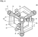
- Fig. 4 is a sectional view in IV-IV in Fig. 2 .
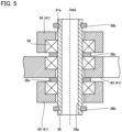
- Fig. 5 is an enlarged sectional view in V-V in Fig. 4 .
- spherical surface link mechanism 100 includes a proximal end link hub 10, a distal end link hub 20, a plurality of links 30, a plurality of intermediate link hubs 40, and bearings 50.
- Proximal end link hub 10 has, for example, a plate-like shape.
- Proximal end link hub 10 includes a first surface 10a and a second surface 10b. Second surface 10b is the opposite surface of first surface 10a.
- a projecting section 10c is provided in proximal end link hub 10. Projecting section 10c is provided on first surface 10a. Projecting section 10c projects in a direction from second surface 10b to first surface 10a.
- a through-hole (not shown) is formed in projecting section 10c.
- the center axis of proximal end link hub 10 is sometimes referred to as a center axis CL1.
- Distal end link hub 20 has, for example, a plate-like shape.
- Distal end link hub 20 includes a first surface 20a and a second surface 20b.
- Second surface 20b is the opposite surface of first surface 20a and faces the first surface 10a side.
- a projecting section 20c is provided in distal end link hub 20.
- Projecting section 20c is provided on second surface 20b. Projecting section 20c projects in a direction from first surface 20a to second surface 20b.
- a through-hole (not shown) is formed in projecting section 20c.
- the center axis of distal end link hub 20 is sometimes referred to as a center axis CL2.
- an end effector is attached to the first surface 20a side of distal end link hub 20.
- Each of plurality of links 30 includes a first end link member 31, a second end link member 32, and an intermediate link member 33.
- the number of plurality of links 30 is, for example, three. However, the number of plurality of links 30 may be two or four or more.
- Plurality of links 30 preferably have the same shape.
- First end link member 31 is rotatably coupled, at one end, to proximal end link hub 10. More specifically, a through-hole (not shown) is formed at one end of first end link member 31. A shaft member 34 is inserted through both of the through-hole formed at one end of first end link member 31 and the through-hole formed in projecting section 10c. Consequently, first end link member 31 is coupled, at one end, to proximal end link hub 10 to be rotatable about the center axis of shaft member 34 (hereinafter sometimes referred to as a first rotation axis RA1). First end link member 31 has, for example, an L shape.
- Second end link member 32 is rotatably coupled, at one end, to distal end link hub 20. More specifically, a through-hole (not shown) is formed at one end of second end link member 32. A shaft member 35 is inserted through both of the through-hole formed at one end of second end link member 32 and through-hole formed in projecting section 20c. Consequently, second end link member 32 is coupled, at one end, to distal end link hub 20 to be rotatable about the center axis of shaft member 35 (hereinafter sometimes referred to as a second rotation axis RA2). Second end link member 32 has, for example, an L shape.
- Intermediate link member 33 is rotatably coupled, at one end, to the other end of first end link member 31. More specifically, a through-hole (not shown) is formed at one end of intermediate link member 33. A through-hole (not shown) is formed at the other end of first end link member 31. A shaft member 36 is inserted through both of the through-hole formed at one end of intermediate link member 33 and the through-hole formed at the other end of first end link member 31.
- intermediate link member 33 is coupled, at one end, to the other end of first end link member 31 to be rotatable about the center axis of shaft member 36 (hereinafter sometimes referred to as a third rotation axis RA3).
- Intermediate link member 33 is rotatably coupled, at the other end, to the other end of the second end link member 32. More specifically, a through-hole (not shown) is formed at the other end of intermediate link member 33. A through-hole (not shown) is formed at the other end of second end link member 32. A shaft member 37 is inserted through both of the through-hole formed at the other end of intermediate link member 33 and the through-hole formed at the other end of second end link member 32.
- intermediate link member 33 is coupled, at the other end, to the other end of second end link member 32 to be rotatable about the center axis of shaft member 37 (hereinafter sometimes referred to as a fourth rotation axis RA4).
- Each of plurality of intermediate link hubs 40 includes a coupling section 41 and a beam section 42.
- a through-hole 41a is formed in coupling section 41.
- Beam section 42 is connected, at one end, to coupling section 41 and connected, at the other end, to intermediate link member 33.
- Coupling section 41 is located on the inner side of plurality of links 30.
- Intermediate link member 33 and intermediate link hubs 40 are, for example, one member.
- plurality of intermediate link hubs 40 are mutually rotatably coupled in coupling sections 41. More specifically, a shaft member 38 is inserted through through-hole 41a of each of plurality of intermediate link hubs 40. Consequently, plurality of intermediate link hubs 40 are coupled to one another to be rotatable about the center axis of shaft member 38 (hereinafter sometimes referred to as a fifth rotation axis RA5).
- a through-hole 38a is formed in shaft member 38.
- Through-hole 38a pierces through shaft member 38 along fifth rotation axis RA5.
- shaft member 38 is a hollow member.
- shaft member 38 may be a solid member.
- a cable connected to the end effector attached to distal end link hub 20 is inserted through through-hole 38a.
- Retaining rings 38b are attached to both the end portions of shaft member 38. Consequently, plurality of intermediate link hubs 40 (coupling sections 41) are prevented from coming off shaft member 38.
- Retaining rings 38b are, for example, C rings or E rings.
- Spacers 38c are attached to shaft member 38. Consequently, plurality of intermediate link hubs 40 (coupling sections 41) are separated from one another.
- Bearings 50 are disposed on the inside of through-hole 41a. Consequently, friction between shaft member 38 and intermediate link hubs 40 (coupling sections 41) is reduced. Bearings 50 are not particularly limited if bearings 50 can reduce the friction between shaft member 38 and intermediate link hubs 40 (coupling sections 41).
- Bearings 50 are, for example, rolling bearings or slide bearings.
- the rolling bearings are capable of supporting a radial load (a load in a direction orthogonal to fifth rotation axis RA5) and an axial load (a load in a direction parallel to fifth rotation axis RA5). Note that bearings 50 only have to be provided between at least one of plurality of intermediate link hubs 40 and shaft member 38.
- Fig. 6 is a schematic diagram showing a mutual relation between center axis CL1 and center axis CL2 and first rotation axis RA1 to fifth rotation axis RA5.
- center axis CL1, first rotation axis RA1, and third rotation axis RA3 cross at one point.
- This one point is referred to as a spherical surface link center point P1.
- Center axis CL2, second rotation axis RA2, and fourth rotation axis RA4 cross at one point.
- This one point is referred to as a spherical surface link center point P2.
- a spherical surface centering on spherical surface link center point P1 is referred to as a moving spherical surface SP1.
- Proximal end link hub 10 moves on moving spherical surface SP1.
- a spherical surface centering on spherical surface link center point P2 is referred to as a moving spherical surface SP2.
- Distal end link hub 20 moves on moving spherical surface SP2. That is, spherical surface link mechanism 100 has structure in which two spherical surface link mechanisms are combined.
- Fifth rotation axis RA5 passes both of spherical surface link center point P1 and spherical surface link center point P2. From another viewpoint, fifth rotation axis RA5 passes the center of a surface (an intermediate plane IP having a circular shape) where moving spherical surface SP1 and moving spherical surface SP1 cross and is orthogonal to intermediate plane IP. The relation explained above always holds irrespective of the positions and the postures of proximal end link hub 10 and distal end link hub 20.
- a configuration of the spherical surface link mechanism according to the comparative example is the same as the configuration of spherical surface link mechanism 100 except that the spherical surface link mechanism according to the comparative example does not include intermediate link hubs 40.
- intermediate link members 33 of plurality of links 30 are mutually rotatably coupled by plurality of intermediate link hubs 40.
- fifth rotation axis RA5 passes spherical surface link center point P1 and spherical surface link center point P2. Therefore, with spherical surface link mechanism 100, it is possible to move proximal end link hub 10 and distal end link hub 20 as in the spherical surface link mechanism according to the comparative example.
- spherical surface link mechanism 100 plurality of links 30 are coupled to one another by intermediate link hubs 40.
- rigidity is improved by coupling plurality of intermediate link hubs 40 to one another. Therefore, the rigidity improvement is less easily affected by the volume of the link members and the coupling sections among the link members. In this way, with spherical surface link mechanism 100, it is possible to improve the rigidity without compromising the operation of the spherical surface link mechanism.
- a region into which link 30 does not intrude is present on the inside.
- the cable connected to the end effector can be inserted through the region.
- this region cannot be viewed in the spherical surface link mechanism according to the comparative example.
- plurality of intermediate link hubs 40 coupled to one another are located in a region into which link 30 does not intrude. Therefore, with spherical surface link mechanism 100, it is easy to recognize the region into which link 30 does not intrude present on the inside.
- spherical surface link mechanism 100 since the cable can be inserted through through-hole 38a, it is possible to protect the cable. As a result of the cable being inserted through through-hole 38a, deflection of the cable is suppressed and interference between the cable and link 30 is suppressed. Since through-hole 38a is formed in shaft member 38, it is possible to reduce shaft member 38 in weight.
- shaft member 38 is a member separate from intermediate link hubs 40, it is possible to simplify structure for coupling plurality of intermediate link hubs 40 one another. Eventually, it is possible to reduce manufacturing cost of spherical surface link mechanism 100. Since shaft member 38 follows movement of the cable when the cable is inserted through through-hole 38a, a load on the cable and friction with the cable decrease.
- spherical surface link mechanism 100 since the friction between intermediate link hubs 40 and shaft member 38 is reduced by bearings 50, the life of spherical surface link mechanism 100 is improved. Heat generation from spherical surface link mechanism 100 during operation can be suppressed by this friction reduction.
- bearings 50 When bearings 50 are rolling bearings, bearings 50 can support an axial load in addition to a radial load. When bearings 50 are slide bearings, bearings 50 can be reduced in weight and vibration is less easily transmitted between shaft member 38 and intermediate link hubs 40.
- a simulation for applying a load of 100 N between proximal end link hub 10 and distal end link hub 20 in a state in which proximal end link hub 10 and distal end link hub 20 are opposed and calculating stress and displacement in the members of the spherical surface link mechanism was implemented using a finite element analysis method. Note that, in this simulation, the members constituting the spherical surface link mechanism according to the comparative example and spherical surface link mechanism 100 were formed by steel.
- distal end link hub 20 was displaced 0.148 mm toward the proximal end link hub 10 side.
- distal end link hub 20 was displaced 0.059 mm toward proximal end link hub 10.
- a displacement amount of distal end link hub 20 in spherical surface link mechanism 100 was less than 50 percent of a displacement amount of distal end link hub 20 in the spherical surface link mechanism according to the comparative example.
- a safety factor (a value obtained by dividing yield stress of a material constituting the members constituting the spherical surface link mechanism by maximum stress applied to the members) of the spherical surface link mechanism according to the comparative example was 6.723.
- a safety factor of spherical surface link mechanism 100 was 8.763. In this way, with spherical surface link mechanism 100, it has been clarified in the simulation that the displacement of distal end link hub 20 is suppressed and the load of distal end link hub 20 is dispersed and the safety factor increases, that is, the rigidity is improved.
- spherical surface link mechanism 200 A spherical surface link mechanism according to a second embodiment (hereinafter, "spherical surface link mechanism 200") is explained.
- spherical surface link mechanism 200 differences from spherical surface link mechanism 100 are mainly explained and redundant explanation is not repeated.
- Spherical surface link mechanism 200 includes proximal end link hub 10, distal end link hub 20, plurality of links 30, plurality of intermediate link hubs 40, and bearings 50.
- the configuration of spherical surface link mechanism 200 is common to the configuration of spherical surface link mechanism 100.
- Fig. 7 is an enlarged sectional view of spherical surface link mechanism 200.
- Fig. 7 an enlarged sectional view of spherical surface link mechanism 200 in a position corresponding to Fig. 5 is shown.
- shaft member 38 is formed integrally with one of plurality of intermediate link hubs 40 (shaft member 38 is a part of one of plurality of intermediate link hubs 40).
- the configuration of spherical surface link mechanism 200 is different from the configuration of spherical surface link mechanism 100.
- shaft member 38 is formed integrally with one of plurality of intermediate link hubs 40, it is possible to reduce the number of bearings 50. More specifically, in spherical surface link mechanism 100, since shaft member 38 is the member separate from intermediate link hubs 40, three bearings 50 in total are necessary. On the other hand, in spherical surface link mechanism 200, since shaft member 38 is formed integrally with one of plurality of intermediate link hubs 40, two number of bearings 50 are enough. In this way, with spherical surface link mechanism 200, it is possible to reduce the number of bearings 50. Therefore, it is possible to reduce manufacturing cost.
- spherical surface link mechanism 300 A spherical surface link mechanism according to a third embodiment (hereinafter, "spherical surface link mechanism 300") is explained. Here, differences from spherical surface link mechanism 100 are mainly explained and redundant explanation is not repeated.
- a configuration of spherical surface link mechanism 300 is explained below.
- Spherical surface link mechanism 300 includes proximal end link hub 10, distal end link hub 20, plurality of links 30, plurality of intermediate link hubs 40, and bearings 50 (not shown in Fig. 8 ).
- the configuration of spherical surface link mechanism 300 is common to the configuration of spherical surface link mechanism 100.
- Fig. 8 is a perspective view of spherical surface link mechanism 300. As shown in Fig. 8 , in spherical surface link mechanism 300, coupling sections 41 are located on the outer side of plurality of links 30. In this regard, the configuration of spherical surface link mechanism 300 is different from the configuration of spherical surface link mechanism 100.
- Fig. 9 is an enlarged sectional view of spherical surface link mechanism 300.
- illustration of the components other than intermediate link member 33, shaft member 38, and intermediate link hubs 40 is omitted.
- shaft member 38 is inserted through through-hole 41a, whereby coupling sections 41 of plurality of intermediate link hubs 40 are coupled to be rotatable about fifth rotation axis RA5.
- a through-hole 38d for inserting through beam section 42 is formed in shaft member 38.
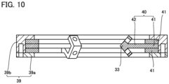
- Fig. 10 is an enlarged sectional view of spherical surface link mechanism 300 according to a first modification.
- spherical surface link mechanism 300 may include outer ring 39 instead of shaft member 38.
- Outer ring 39 is disposed on the outer side of coupling section 41 of each of plurality of intermediate link hubs 40 and holds coupling section 41 of each of plurality of intermediate link hubs 40 to be rotatable about fifth rotation axis RA5.
- outer ring 39 includes a first member 39a and a second member 39b. First member 39a and second member 39b are coupled to each other in a state in which coupling section 41 of each of plurality of intermediate link hubs 40 is sandwiched between first member 39a and second member 39b.
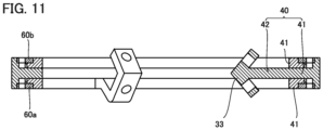
- Fig. 11 is an enlarged sectional view of spherical surface link mechanism 300 according to a second modification.
- illustration of the components other than intermediate link members 33, a falling-off preventing ring 60a, a falling-off preventing ring 60b, and intermediate link hubs 40 is omitted.
- spherical surface link mechanism 300 may include falling-off preventing ring 60a and falling-off preventing ring 60b instead of outer ring 39.
- Coupling section 41 of one intermediate link hub 40 is sandwiched by coupling sections 41 of other two intermediate link hubs 40. Falling-off preventing ring 60a and falling-off preventing ring 60b are attached to coupling section 41 of one intermediate link hub 40. Falling-off preventing ring 60a and falling-off preventing ring 60b sandwich coupling section 41 of each of plurality of intermediate link hubs 40. Consequently, coupling section 41 of each of plurality of intermediate link hubs 40 is held to be rotatable about fifth rotation axis RA5.
- spherical surface link mechanism 100 and spherical surface link mechanism 300 by rotating each of plurality of intermediate link hubs 40 about fifth rotation axis RA5 with a driving source (not shown), it is possible to respectively symmetrically move proximal end link hub 10 and distal end link hub 20 with respect to intermediate plane IP.
- spherical surface link actuating device 400 A spherical surface link actuating device according to a fourth embodiment (hereinafter, "spherical surface link actuating device 400") is explained.
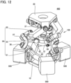
- Fig. 12 is a perspective view of spherical surface link actuating device 400.
- spherical surface link actuating device 400 includes spherical surface link mechanism 100 and a plurality of driving sources 500.
- the number of plurality of driving sources 500 is two or more.
- the number of plurality of driving sources 500 may be smaller than the number of plurality of links 30.
- Driving source 500 is, for example, a motor.
- Plurality of driving sources 500 are attached to spherical surface link mechanism 100.
- Each of plurality of driving sources 500 rotates first end link member 31 of each of plurality of links 30 about first rotation axis RA1. Consequently, it is possible to change the position and the posture of distal end link hub 20 with respect to proximal end link hub 10.
- each of plurality of driving sources 500 may rotate second end link member 32 of each of plurality of links 30 about second rotation axis RA2. Consequently, it is possible to change the position and the posture of proximal end link hub 10 with respect to distal end link hub 20.
- spherical surface link mechanism 200 may be used instead of spherical surface link mechanism 100.
- spherical surface link mechanism 300 may be used instead of spherical surface link mechanism 100.
- each of plurality of driving sources 500 can respectively symmetrically move proximal end link hub 10 and distal end link hub 20 with respect to intermediate plane IP by rotating each of plurality of intermediate link hubs 40 about fifth rotation axis RA5.
- spherical surface link actuating device 400 when each of plurality of driving sources 500 rotates first end link member 31 of each of plurality of links 30 about first rotation axis RA1 to thereby change the position and the posture of distal end link hub 20 with respect to proximal end link hub 10, it is possible to reduce an inertial moment involved in the movement of distal end link hub 20.
- spherical surface link actuating device 400 when each of plurality of driving sources 500 rotates each of plurality of intermediate link hubs 40 about fifth rotation axis RA5 to thereby change the position and the posture of distal end link hub 20 with respect to proximal end link hub 10, since proximal end link hub 10 and distal end link hub 20 are symmetrically moved, it is possible to reduce accumulation of errors such as backlash.
- link actuating device 600 A link actuating device according to a fifth embodiment (hereinafter referred to as "link actuating device 600") is explained.
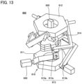
- Fig. 13 is a perspective view of link actuating device 600.
- Fig. 14 is a front view of link actuating device 600.
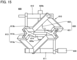
- Fig. 15 is a side view of link actuating device 600.
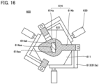
- Fig. 16 is a sectional view in XVI-XVI in Fig. 15 .
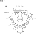
- Fig. 17 is a plan view of link actuating device 600.
- Fig. 18 is a sectional view in XVIII-XVIII in Fig. 17 .
- link actuating device 600 includes a spherical surface link mechanism 610, an origin positioning member 620, and a driving source 630.
- Spherical surface link mechanism 610 includes a proximal end link hub 611, a distal end link hub 612, a plurality of links 613, and a plurality of intermediate link hubs 614.
- Proximal end link hub 611 and distal end link hub 612 are, for example, flat. However, the shape of proximal end link hub 611 and distal end link hub 612 is not limited to this. In the following explanation, the center axis of proximal end link hub 611 is referred to as a first center axis and the center axis of distal end link hub 612 is referred to as a second center axis. Although not shown, an end effector is attached to, for example, distal end link hub 612.
- the number of plurality of links 613 is, for example, three. However, the number of plurality of links 613 may be four or more. Plurality of links 613 are disposed, for example, at equal intervals, in a direction along a circumference centering on the first center axis.
- Link 613 includes a first end link member 613a, a second end link member 613b, and an intermediate link member 613c.
- First end link member 613a is coupled, at one end of first end link member 613a, to proximal end link hub 611 to be rotatable about a first rotation axis.
- Second end link member 613b is coupled, at one end of second end link member 613b, to distal end link hub 612 to be rotatable about a second rotation axis.
- First end link member 613a and second end link member 613b are, for example, L-shaped.
- Intermediate link member 613c is coupled, at one end of intermediate link member 613c, to the other end of first end link member 613a to be rotatable about a third rotation axis.
- Intermediate link member 613c is coupled, at the other end of intermediate link member 613c, to the other end of second end link member 613b to be rotatable about a fourth rotation axis.
- Intermediate link member 613c has, for example, an L shape.
- the first rotation axis, the third rotation axis, and the first center axis cross at a first spherical surface link center point.
- the second rotation axis, the fourth rotation axis, and the second center axis cross at a second spherical surface link center point. Therefore, proximal end link hub 611 moves on a spherical surface (a first moving spherical surface) centering on the first spherical surface link center point and distal end link hub 612 moves on a spherical surface (a second moving spherical surface) centering on the second spherical surface link center point. That is, spherical surface link mechanism 610 has structure in which two spherical surface link mechanisms are combined.
- the number of plurality of intermediate link hubs 614 is equal to the number of plurality of links 613.
- Intermediate link hub 614 includes a coupling section 614a and a beam section 614b.
- Coupling section 614a is disposed on the inner side of plurality of links 613.
- Coupling sections 614a of plurality of intermediate link hubs 614 are coupled to one another to be rotatable about a fifth rotation axis.
- the fifth rotation axis passes both of the first spherical surface link center point and the second spherical surface link center point. From another viewpoint, the fifth rotation axis passes the center of a surface (an intermediate plane having a circular shape) where the first moving spherical surface and the second moving spherical surface cross and is orthogonal to the intermediate plane. This always holds irrespective of the positions and the postures of proximal end link hub 611 and distal end link hub 612. Therefore, spherical surface link mechanism 610 is capable of performing the same operation as an operation performed when spherical surface link mechanism 610 does not include plurality of intermediate link hubs 614.
- a first through-hole 614aa is formed in coupling section 614a.
- First through-hole 614aa pierces through coupling section 614a in the direction of the fifth rotation axis.
- First through-holes 614aa of plurality of intermediate link hubs 614 overlap one another.
- a first groove 614ab and a second groove 614ac are formed on the inner wall surface of first through-hole 614aa.
- First groove 614ab and second groove 614ac extend from the inner wall surface of first through-hole 614aa toward the radial direction outer side of first through-hole 614aa.
- First groove 614ab and second groove 614ac are present in positions symmetrical with respect to the center of first through-hole 614aa.
- First groove 614ab and second groove 614ac of each of plurality of intermediate link hubs 614 are formed to overlap each other when distal end link hub 612 is present in an origin position.
- Distal end link hub 612 is present in the origin position when the second center axis is present on the same straight line as the first center axis (when a bending angle of spherical surface link mechanism 610 is 0°).
- Beam section 614b is connected, at one end of beam section 614b, to coupling section 614a. Beam section 614b is connected, at the other end of beam section 614b, to intermediate link member 613c. Intermediate link hub 614 (coupling section 614a and beam section 614b) may be formed integrally with intermediate link member 613c.
- Origin positioning member 620 is plate-like. Origin positioning member 620 includes a first end 620a and a second end 620b. First end 620a and second end 620b are ends in the longitudinal direction of origin positioning member 620. Second end 620b is an end on the opposite side of first end 620a.
- Origin positioning member 620 includes a first portion 621 and a second portion 622.
- First portion 621 is a portion on the first end 620a side of origin positioning member 620.
- Second portion 622 is a portion on the second end 620b side of origin positioning member 620.
- the width of first portion 621 in a direction orthogonal to the longitudinal direction of origin positioning member 620 is larger than the width of second portion 622 in the direction orthogonal to the longitudinal direction of origin positioning member 620.
- the width of first portion 621 in the direction orthogonal to the longitudinal direction of origin positioning member 620 decreases toward first end 620a.
- Origin positioning member 620 is inserted into first through-hole 614aa (more specifically, first groove 614ab and second groove 614ac) of each of intermediate link hubs 614 when distal end link hub 612 is present in the origin position, whereby plurality of intermediate link hubs 614 become incapable of mutually rotating about the fifth rotation axis.
- origin positioning member 620 disables at least two or more among plurality of intermediate link hubs 614 to rotate about the fifth rotation axis.
- Driving source 630 is, for example, a motor.
- the number of plurality of driving sources 630 is equal to, for example, the number of plurality of links 613. However, the number of plurality of driving sources 630 may be smaller than the number of plurality of links 613 if the number of plurality of driving sources 630 is two or more.
- Each of plurality of driving sources 630 rotates first end link member 613a of each of plurality of links 613 about the first rotation axis. The position and the posture of distal end link hub 612 are changed by changing an amount of the rotation.
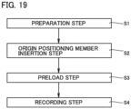
- Fig. 19 is a flowchart showing an origin positioning method in link actuating device 600.
- the origin positioning method in link actuating device 600 includes a preparation step S1, an origin positioning member insertion step S2, a preload step S3, and a recording step S4.
- Origin positioning member insertion step S2 is performed after preparation step S1.
- Preload step S3 is performed after origin positioning member insertion step S2.
- Recording step S4 is performed after preload step S3.
- link actuating device 600 is prepared.
- driving source 630 adjusts an amount of rotating first end link member 613a about the first rotation axis to thereby move distal end link hub 612 to the origin position.
- origin positioning member insertion step S2 secondly, origin positioning member 620 is inserted into first through-hole 614aa (first groove 614ab and second groove 614ac) of each of plurality of intermediate link hubs 614. Consequently, origin positioning member 620 becomes incapable of rotating about the fifth rotation axis of plurality of intermediate link hubs 614. Distal end link hub 612 is fixed to the origin position.
- each of plurality of driving sources 630 generates torque for rotating first end link member 613a of each of plurality of links 613 about the first rotation axis, whereby preload is applied on each of plurality of links 613.
- recording step S4 torque of each of plurality of driving sources 630 in a state in which the preload explained above is applied is recorded or output.
- an operation amount of each of plurality of driving sources 630 may be recorded or output or the position of each of plurality of links 613 may be recorded or output instead of the torque of each of plurality of driving sources 630.
- the recorded or output torque of each of plurality of driving sources 630 (the operation amount of each of plurality of driving sources 630 or the position of each of plurality of links 613) is reflected on an output of each of plurality of driving sources 630 during the operation of link actuating device 600. Consequently, it is possible to suppress backlash of rotation pair units during the operation of link actuating device 600.
- link actuating device 600 by inserting origin positioning member 620 into first through-holes 614aa of plurality of intermediate link hubs 614, it is possible to perform origin positioning for distal end link hub 612. Therefore, in link actuating device 600, in the origin positioning for distal end link hub 612, origin positioning member 620 is suppressed from interfering with the end effector attached to distal end link hub 612.
- link actuating device 600A A link actuating device according to a sixth embodiment (hereinafter referred to as "link actuating device 600A") is explained. Here, differences from link actuating device 600 are mainly explained and redundant explanation is not repeated.
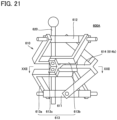
- Fig. 20 is a perspective view of link actuating device 600A.
- Fig. 21 is a front view of link actuating device 600A.
- Fig. 22 is a sectional view in XXII-XXII in Fig. 21 .
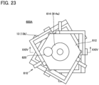
- Fig. 23 is a plan view of link actuating device 600A.
- Fig. 24 is a sectional view in XXIV-XXIV in Fig. 23 . Note that, in Fig. 20 to Fig. 24 , illustration of driving source 630 is omitted.
- a second through-hole 614ad is formed in coupling section 614a of each of plurality of intermediate link hubs 614.
- Second through-hole 614ad pierces through coupling section 614a in the direction of the fifth rotation axis. Second through-hole 614ad is present in a position deviating from the center of coupling section 614a. Second through-holes 614ad of plurality of intermediate link hubs 614 are formed to overlap one another when distal end link hub 612 is present in the origin position.
- origin positioning member 620 is inserted into second through-hole 614ad of each of plurality of intermediate link hubs 614. Consequently, plurality of intermediate link hubs 614 become incapable of mutually rotating about the fifth rotation axis. Note that, in link actuating device 600A, origin positioning member 620 is bar-like.
- a third through-hole 611a is formed in proximal end link hub 611 and a fourth through-hole 612a is formed in distal end link hub 612.
- Third through-hole 611a is formed in a position deviating from the center of proximal end link hub 611.
- Fourth through-hole 612a is present in a position deviating from the center of distal end link hub 612.
- third through-hole 611a and fourth through-hole 612a are present in positions where third through-hole 611a and fourth through-hole 612a overlap second through-hole 614ad of each of plurality of intermediate link hubs 614.
- origin positioning member 620 is inserted into third through-hole 611a and fourth through-hole 612a in addition to second through-hole 614ad of each of plurality of intermediate link hubs 614.
- link actuating device 600A when distal end link hub 612 is present in the origin position, origin positioning member 620 is inserted into second through-hole 614ad of each of plurality of intermediate link hubs 614, whereby plurality of intermediate link hubs 614 become incapable of mutually rotating about the fifth rotation axis. Therefore, in link actuating device 600A, in the origin positioning for distal end link hub 612, origin positioning member 620 is suppressed from interfering with the end effector attached to distal end link hub 612.
- link actuating device 600A when distal end link hub 612 is present in the origin position, origin positioning member 620 is inserted into third through-hole 611a and fourth through-hole 612a in addition to second through-hole 614ad of each of plurality of intermediate link hubs 614. Therefore, in link actuating device 600A, the origin positioning for distal end link hub 612 by origin positioning member 620 is more firmly performed. Note that, since fourth through-hole 612a is present in a position deviating from the center of distal end link hub 612, in the origin positioning for distal end link hub 612, origin positioning member 620 less easily interferes with the end effector attached to distal end link hub 612.
- link actuating device 600B A link actuating device according to a seventh embodiment (hereinafter referred to as "link actuating device 600B") is explained. Here, differences from link actuating device 600A are mainly explained and redundant explanation is not repeated.
- Fig. 25 is a perspective view of link actuating device 600B.
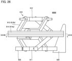
- Fig. 26 is a front view of link actuating device 600B.
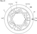
- Fig. 27 is a plan view of link actuating device 600B.
- Fig. 28 is a sectional view in XXVIII-XXVIII in Fig. 26 .
- Fig. 29 is a sectional view in XXIX-XXIX in Fig. 27 .
- coupling section 614a is disposed on the outer side of plurality of links 613.
- coupling section 614a is annular.
- second through-hole 614ad is formed in a slit shape on the outer circumferential surface of coupling section 614a.
- second through-hole 614ad extends from the outer circumferential surface of coupling section 614a to the radial direction inner side of coupling section 614a.
- origin positioning member 620 is plate-like. In link actuating device 600B, when distal end link hub 612 is present in the origin position, origin positioning member 620 is inserted into second through-hole 614ad of each of plurality of intermediate link hubs 614. Consequently, plurality of intermediate link hubs 614 become incapable of mutually rotating about the fifth rotation axis.
- link actuating device 600B when distal end link hub 612 is present in the origin position, origin positioning member 620 is inserted into second through-hole 614ad of each of plurality of intermediate link hubs 614, whereby plurality of intermediate link hubs 614 become incapable of mutually rotating about the fifth rotation axis.
- coupling section 614a is disposed on the outer side of plurality of links 613. Therefore, in link actuating device 600B, in the origin positioning for distal end link hub 612, origin positioning member 620 is suppressed from interfering with the end effector attached to distal end link hub 612.
- link actuating device 600C In a link actuating device according to an eighth embodiment (hereinafter referred to as "link actuating device 600C”) is explained. Here, differences from link actuating device 600A are mainly explained and redundant explanation is not repeated.
- Fig. 30 is a perspective view of link actuating device 600C.
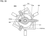
- Fig. 31 is a front view of link actuating device 600C.
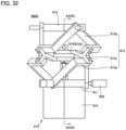
- Fig. 32 is a side view of link actuating device 600C.
- Fig. 33 is a sectional view in XXXIII-XXXIII in Fig. 31 .
- Fig. 34 is a sectional view in XXXIV-XXXIV in Fig. 32 .
- Fig. 35 is an enlarged view in a region XXXV in Fig. 34 .
- spherical surface link mechanism 610 further includes a housing member 615. Housing member 615 is attached to proximal end link hub 611.
- one intermediate link hub 614 among plurality of intermediate link hubs 614 is referred to as a first intermediate link hub and other intermediate link hubs 614 among plurality of intermediate link hubs 614 are referred to as second intermediate link hubs.
- coupling section 614a of the first intermediate link hub includes a shaft section 614c.
- Shaft section 614c has a tubular shape extending in the direction of the fifth rotation axis.
- Coupling section 614a of the second intermediate link hub is attached to shaft section 614c to be rotatable about shaft section 614c. Consequently, coupling sections 614a of plurality of intermediate link hubs 614 are capable of mutually rotating about the fifth rotation axis.
- rotation resistance reducing members 616 are disposed between shaft section 614c and coupling section 614a of the second intermediate link hub. Consequently, rotation resistance between shaft section 614c and coupling section 614a of the second intermediate link hub is reduced.
- Rotation resistance reducing members 616 are, for example, rolling bearings or slide bearings.
- origin positioning member 620 when distal end link hub 612 is present in the origin position, origin positioning member 620 is inserted into second through-hole 614ad. Consequently, plurality of intermediate link hubs 614 become incapable of mutually rotating about the fifth rotation axis. Note that, when distal end link hub 612 is present in the origin position, origin positioning member 620 may be inserted into shaft section 614c in addition to second through-hole 614ad.
- origin positioning member 620 may include a grasping section 623. In link actuating device 600C, by lifting grasping section 623 upward when distal end link hub 612 is present in the origin position, origin positioning member 620 is inserted into second through-hole 614ad and shaft section 614c.
- origin positioning member 620 is housed in housing member 615. That is, in link actuating device 600C, origin positioning member 620 is held by spherical surface link mechanism 610. However, in origin positioning member 620, a portion inserted into second through-hole 614ad and shaft section 614c and grasping section 623 are located on the outside of housing member 615.
- link actuating device 600C when distal end link hub 612 is present in the origin position, origin positioning member 620 is inserted into second through-hole 614ad of each of plurality of intermediate link hubs 614, whereby plurality of intermediate link hubs 614 become incapable of mutually rotating about the fifth rotation axis. Therefore, in link actuating device 600B, in origin positioning for distal end link hub 612, origin positioning member 620 is suppressed from interfering with the end effector attached to distal end link hub 612.
- origin positioning member 620 is held by spherical surface link mechanism 610 (housing member 615). Therefore, in link actuating device 600C, loss and drop of origin positioning member 620 are suppressed.
- link actuating device 600D A link actuating device according to a ninth embodiment (hereinafter referred to as "link actuating device 600D") is explained. Here, differences from link actuating device 600A are mainly explained and redundant explanation is not repeated.
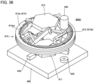
- Fig. 36 is a perspective view of link actuating device 600D.
- Fig. 37 is a plan view of link actuating device 600D.
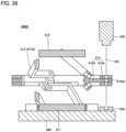
- Fig. 38 is a sectional view in XXXVIII-XXXVIII in Fig. 37 .
- link actuating device 600D includes a light source 640, a detector 650, and a stand 660. However, link actuating device 600D does not include origin positioning member 620.
- link actuating device 600D spherical surface link mechanism 610 and detector 650 are disposed on stand 660.
- coupling section 614a is disposed on the outer side of plurality of links 613.
- coupling section 614a is annular.
- Light source 640 generates light 641.
- Light source 640 is, for example, a laser oscillator.
- Light 641 is laser light.
- Second through-holes 614ad of plurality of intermediate link hubs 614 overlap one another when distal end link hub 612 is present in the origin position.
- Light 641 is applied to detector 650 passing through second through-hole 614ad of each of plurality of intermediate link hubs 614 when distal end link hub 612 is present in the origin position.
- distal end link hub 612 is absent from the origin position, light 641 is blocked by coupling section 614a of each of plurality of intermediate link hubs 614 and is not applied to detector 650.
- Detector 650 is for example, a photodiode. Therefore, it is detected based on the output signal from detector 650 that distal end link hub 612 is present in the origin position.
- An encoder 614ae is provided in coupling section 614a.
- a value of encoder 614ae is recorded.
- link actuating device 600D by allowing light 641 to pass through second through-holes 614ad of plurality of intermediate link hubs 614, it is possible to perform the origin positioning for distal end link hub 612. Therefore, in link actuating device 600, it is unnecessary to use origin positioning member 620 in origin positioning for distal end link hub 612. Origin positioning member 620 is suppressed from interfering the end effector attached to distal end link hub 612.
- 100 Spherical surface link mechanism 10 Proximal end link hub, 10a First surface, 10b Second surface, 10c Projecting section, 20 Distal end link hub, 20a First surface, 20b Second surface, 20c Projecting section, 30 Link, 31 First end link member, 32 Second end link member, 33 Intermediate link member, 34, 35, 36, 37, 38 Shaft member, 38a Through-hole, 38b Retaining ring, 38c Spacer, 38d Through-hole, 39 Outer ring, 39a First member, 39b Second member, 40 Intermediate link hub, 41 Coupling section, 41a Through-hole, 42 Beam section, 50 Bearing, 60a, 60b Falling-off preventing ring, 200 Spherical surface link mechanism, 300 Spherical surface link mechanism, 400 Spherical surface link actuating device, 500 Driving source, CL1, CL2 Center axis, IP Intermediate plane, P1 Spherical surface link center point, P2 Spherical surface link center point, RA1 First rotation axis, RA2 Second rotation axis, RA
Landscapes
- Engineering & Computer Science (AREA)
- Mechanical Engineering (AREA)
- General Engineering & Computer Science (AREA)
- Robotics (AREA)
- Transmission Devices (AREA)
- Manipulator (AREA)
Applications Claiming Priority (4)
| Application Number | Priority Date | Filing Date | Title |
|---|---|---|---|
| JP2020180482A JP2022071492A (ja) | 2020-10-28 | 2020-10-28 | 球面リンク機構及び球面リンク作動装置 |
| JP2021028730A JP7612451B2 (ja) | 2021-02-25 | 2021-02-25 | リンク作動装置及び原点位置決め方法 |
| PCT/JP2021/039435 WO2022092064A1 (ja) | 2020-10-28 | 2021-10-26 | 球面リンク機構、球面リンク作動装置、リンク作動装置及び原点位置決め方法 |
| EP21886182.1A EP4238716B1 (de) | 2020-10-28 | 2021-10-26 | Verbindungsmechanismus mit sphärischer oberfläche und betätigungsvorrichtung für verbindungselement mit sphärischer oberfläche |
Related Parent Applications (2)
| Application Number | Title | Priority Date | Filing Date |
|---|---|---|---|
| EP21886182.1A Division EP4238716B1 (de) | 2020-10-28 | 2021-10-26 | Verbindungsmechanismus mit sphärischer oberfläche und betätigungsvorrichtung für verbindungselement mit sphärischer oberfläche |
| EP21886182.1A Division-Into EP4238716B1 (de) | 2020-10-28 | 2021-10-26 | Verbindungsmechanismus mit sphärischer oberfläche und betätigungsvorrichtung für verbindungselement mit sphärischer oberfläche |
Publications (3)
| Publication Number | Publication Date |
|---|---|
| EP4520482A2 true EP4520482A2 (de) | 2025-03-12 |
| EP4520482A3 EP4520482A3 (de) | 2025-05-14 |
| EP4520482B1 EP4520482B1 (de) | 2026-04-15 |
Family
ID=81382508
Family Applications (2)
| Application Number | Title | Priority Date | Filing Date |
|---|---|---|---|
| EP25151116.8A Active EP4520482B1 (de) | 2020-10-28 | 2021-10-26 | Gelenkbetätigungsvorrichtung und ursprungspositionierungsverfahren |
| EP21886182.1A Active EP4238716B1 (de) | 2020-10-28 | 2021-10-26 | Verbindungsmechanismus mit sphärischer oberfläche und betätigungsvorrichtung für verbindungselement mit sphärischer oberfläche |
Family Applications After (1)
| Application Number | Title | Priority Date | Filing Date |
|---|---|---|---|
| EP21886182.1A Active EP4238716B1 (de) | 2020-10-28 | 2021-10-26 | Verbindungsmechanismus mit sphärischer oberfläche und betätigungsvorrichtung für verbindungselement mit sphärischer oberfläche |
Country Status (4)
| Country | Link |
|---|---|
| US (1) | US12157224B2 (de) |
| EP (2) | EP4520482B1 (de) |
| CN (1) | CN116367971A (de) |
| WO (1) | WO2022092064A1 (de) |
Citations (1)
| Publication number | Priority date | Publication date | Assignee | Title |
|---|---|---|---|---|
| JP6289973B2 (ja) | 2014-03-31 | 2018-03-07 | Ntn株式会社 | パラレルリンク機構およびリンク作動装置 |
Family Cites Families (8)
| Publication number | Priority date | Publication date | Assignee | Title |
|---|---|---|---|---|
| JP2736558B2 (ja) | 1990-01-29 | 1998-04-02 | 株式会社トキメック | 位置測定方法及びその装置 |
| JP3545995B2 (ja) | 2000-06-12 | 2004-07-21 | ファナック株式会社 | ロボットの関節構造 |
| JP5951224B2 (ja) | 2011-11-02 | 2016-07-13 | Ntn株式会社 | リンク作動装置の原点位置初期設定方法およびリンク作動装置 |
| JP6482188B2 (ja) | 2014-06-03 | 2019-03-13 | 川崎重工業株式会社 | ロボットアーム |
| CN105789892A (zh) | 2016-03-24 | 2016-07-20 | 褚宏鹏 | 一种新型并联天线姿态调整机构 |
| CN105773577A (zh) | 2016-03-24 | 2016-07-20 | 褚宏鹏 | 多支链耦合两转动并联机构 |
| JP7022008B2 (ja) | 2018-06-08 | 2022-02-17 | Ntn株式会社 | リンク作動装置 |
| JP7177736B2 (ja) | 2019-03-22 | 2022-11-24 | Ntn株式会社 | パラレルリンク機構およびリンク作動装置 |
-
2021
- 2021-10-26 CN CN202180073566.5A patent/CN116367971A/zh active Pending
- 2021-10-26 WO PCT/JP2021/039435 patent/WO2022092064A1/ja not_active Ceased
- 2021-10-26 US US18/033,767 patent/US12157224B2/en active Active
- 2021-10-26 EP EP25151116.8A patent/EP4520482B1/de active Active
- 2021-10-26 EP EP21886182.1A patent/EP4238716B1/de active Active
Patent Citations (1)
| Publication number | Priority date | Publication date | Assignee | Title |
|---|---|---|---|---|
| JP6289973B2 (ja) | 2014-03-31 | 2018-03-07 | Ntn株式会社 | パラレルリンク機構およびリンク作動装置 |
Also Published As
| Publication number | Publication date |
|---|---|
| EP4238716B1 (de) | 2025-08-20 |
| EP4238716A4 (de) | 2024-09-25 |
| US20230302628A1 (en) | 2023-09-28 |
| CN116367971A (zh) | 2023-06-30 |
| EP4520482A3 (de) | 2025-05-14 |
| EP4520482B1 (de) | 2026-04-15 |
| WO2022092064A1 (ja) | 2022-05-05 |
| US12157224B2 (en) | 2024-12-03 |
| EP4238716A1 (de) | 2023-09-06 |
Similar Documents
| Publication | Publication Date | Title |
|---|---|---|
| EP3816477B1 (de) | Verbindungsbetätigungsvorrichtung | |
| EP3943780B1 (de) | Parallelverbindungsmechanismus und verbindungsbetätigungsvorrichtung | |
| KR101611586B1 (ko) | 동심 다축 액추에이터 | |
| JP2009058388A (ja) | トルクセンサ及びトルクセンサ付モータ | |
| US8556533B2 (en) | Multi-stage flexural pivot | |
| CN105209224B (zh) | 连杆动作装置 | |
| EP4238716B1 (de) | Verbindungsmechanismus mit sphärischer oberfläche und betätigungsvorrichtung für verbindungselement mit sphärischer oberfläche | |
| EP3575751B1 (de) | Rotierender struktureller körper | |
| JP7191496B2 (ja) | 動力伝達装置 | |
| KR20140066018A (ko) | 로봇 관절 유니트 | |
| JP2013064706A (ja) | センサ | |
| JP2012242114A (ja) | 捩れセンサおよび駆動関節機構 | |
| JP5598921B2 (ja) | 回転軸保持機構及びこれを用いた回転粘度計 | |
| JP2000028450A (ja) | トルク検出装置 | |
| JP2008261491A (ja) | デフケース及びこれを備えた車両用差動装置 | |
| EP3771840B1 (de) | Flexibler drehpunkt für weltraumanwendungen | |
| KR101560702B1 (ko) | 회전축 유지 기구 및 이를 이용한 회전축 점도계 | |
| EP3633216A1 (de) | Zweireihiges vierpunktkugellager | |
| WO2023219050A1 (ja) | センサ装置 | |
| WO2022041005A1 (en) | Transmission device, robotic joint, and robot | |
| US11967882B2 (en) | Radially stacked actuator | |
| JP3995692B2 (ja) | トルクと回転速度の一体型検出装置 | |
| JP7612451B2 (ja) | リンク作動装置及び原点位置決め方法 | |
| JP5501702B2 (ja) | トリポード型等速自在継手用ローラカセット、トリポード型等速自在継手用サブアッシー、トリポード型等速自在継手用トリポードキット、およびトリポード型等速自在継手 | |
| JP5834928B2 (ja) | 十字軸式自在継手用ヨーク |
Legal Events
| Date | Code | Title | Description |
|---|---|---|---|
| PUAI | Public reference made under article 153(3) epc to a published international application that has entered the european phase |
Free format text: ORIGINAL CODE: 0009012 |
|
| STAA | Information on the status of an ep patent application or granted ep patent |
Free format text: STATUS: REQUEST FOR EXAMINATION WAS MADE |
|
| 17P | Request for examination filed |
Effective date: 20250124 |
|
| AC | Divisional application: reference to earlier application |
Ref document number: 4238716 Country of ref document: EP Kind code of ref document: P |
|
| AK | Designated contracting states |
Kind code of ref document: A2 Designated state(s): AL AT BE BG CH CY CZ DE DK EE ES FI FR GB GR HR HU IE IS IT LI LT LU LV MC MK MT NL NO PL PT RO RS SE SI SK SM TR |
|
| REG | Reference to a national code |
Ref country code: DE Free format text: PREVIOUS MAIN CLASS: B25J0009000000 Ipc: B25J0011000000 Ref country code: DE Ref legal event code: R079 Ref document number: 602021052393 Country of ref document: DE Free format text: PREVIOUS MAIN CLASS: B25J0009000000 Ipc: B25J0011000000 |
|
| PUAL | Search report despatched |
Free format text: ORIGINAL CODE: 0009013 |
|
| AK | Designated contracting states |
Kind code of ref document: A3 Designated state(s): AL AT BE BG CH CY CZ DE DK EE ES FI FR GB GR HR HU IE IS IT LI LT LU LV MC MK MT NL NO PL PT RO RS SE SI SK SM TR |
|
| RIC1 | Information provided on ipc code assigned before grant |
Ipc: B25J 9/00 20060101ALI20250407BHEP Ipc: B25J 9/16 20060101ALI20250407BHEP Ipc: B25J 9/04 20060101ALI20250407BHEP Ipc: F16H 21/54 20060101ALI20250407BHEP Ipc: F16H 21/46 20060101ALI20250407BHEP Ipc: B25J 11/00 20060101AFI20250407BHEP |
|
| GRAP | Despatch of communication of intention to grant a patent |
Free format text: ORIGINAL CODE: EPIDOSNIGR1 |
|
| STAA | Information on the status of an ep patent application or granted ep patent |
Free format text: STATUS: GRANT OF PATENT IS INTENDED |
|
| RIC1 | Information provided on ipc code assigned before grant |
Ipc: B25J 11/00 20060101AFI20251022BHEP Ipc: F16H 21/46 20060101ALI20251022BHEP Ipc: F16H 21/54 20060101ALI20251022BHEP Ipc: B25J 9/04 20060101ALI20251022BHEP Ipc: B25J 9/16 20060101ALI20251022BHEP Ipc: B25J 9/00 20060101ALI20251022BHEP |
|
| INTG | Intention to grant announced |
Effective date: 20251111 |
|
| RIN1 | Information on inventor provided before grant (corrected) |
Inventor name: SATOU, NAOHIKO |
|
| GRAS | Grant fee paid |
Free format text: ORIGINAL CODE: EPIDOSNIGR3 |
|
| GRAA | (expected) grant |
Free format text: ORIGINAL CODE: 0009210 |
|
| STAA | Information on the status of an ep patent application or granted ep patent |
Free format text: STATUS: THE PATENT HAS BEEN GRANTED |
|
| AC | Divisional application: reference to earlier application |
Ref document number: 4238716 Country of ref document: EP Kind code of ref document: P |
|
| AK | Designated contracting states |
Kind code of ref document: B1 Designated state(s): AL AT BE BG CH CY CZ DE DK EE ES FI FR GB GR HR HU IE IS IT LI LT LU LV MC MK MT NL NO PL PT RO RS SE SI SK SM TR |
|
| REG | Reference to a national code |
Ref country code: CH Ref legal event code: F10 Free format text: ST27 STATUS EVENT CODE: U-0-0-F10-F00 (AS PROVIDED BY THE NATIONAL OFFICE) Effective date: 20260415 |