EP4520509A2 - Ensemble soupape et dispositif de distribution - Google Patents
Ensemble soupape et dispositif de distribution Download PDFInfo
- Publication number
- EP4520509A2 EP4520509A2 EP24220062.4A EP24220062A EP4520509A2 EP 4520509 A2 EP4520509 A2 EP 4520509A2 EP 24220062 A EP24220062 A EP 24220062A EP 4520509 A2 EP4520509 A2 EP 4520509A2
- Authority
- EP
- European Patent Office
- Prior art keywords
- valve
- valve plate
- container
- fastening part
- coupling
- Prior art date
- Legal status (The legal status is an assumption and is not a legal conclusion. Google has not performed a legal analysis and makes no representation as to the accuracy of the status listed.)
- Pending
Links
Images



Classifications
-
- B—PERFORMING OPERATIONS; TRANSPORTING
- B23—MACHINE TOOLS; METAL-WORKING NOT OTHERWISE PROVIDED FOR
- B23K—SOLDERING OR UNSOLDERING; WELDING; CLADDING OR PLATING BY SOLDERING OR WELDING; CUTTING BY APPLYING HEAT LOCALLY, e.g. FLAME CUTTING; WORKING BY LASER BEAM
- B23K20/00—Non-electric welding by applying impact or other pressure, with or without the application of heat, e.g. cladding or plating
- B23K20/10—Non-electric welding by applying impact or other pressure, with or without the application of heat, e.g. cladding or plating making use of vibrations, e.g. ultrasonic welding
-
- B—PERFORMING OPERATIONS; TRANSPORTING
- B23—MACHINE TOOLS; METAL-WORKING NOT OTHERWISE PROVIDED FOR
- B23K—SOLDERING OR UNSOLDERING; WELDING; CLADDING OR PLATING BY SOLDERING OR WELDING; CUTTING BY APPLYING HEAT LOCALLY, e.g. FLAME CUTTING; WORKING BY LASER BEAM
- B23K20/00—Non-electric welding by applying impact or other pressure, with or without the application of heat, e.g. cladding or plating
- B23K20/12—Non-electric welding by applying impact or other pressure, with or without the application of heat, e.g. cladding or plating the heat being generated by friction; Friction welding
-
- B—PERFORMING OPERATIONS; TRANSPORTING
- B29—WORKING OF PLASTICS; WORKING OF SUBSTANCES IN A PLASTIC STATE IN GENERAL
- B29C—SHAPING OR JOINING OF PLASTICS; SHAPING OF MATERIAL IN A PLASTIC STATE, NOT OTHERWISE PROVIDED FOR; AFTER-TREATMENT OF THE SHAPED PRODUCTS, e.g. REPAIRING
- B29C65/00—Joining or sealing of preformed parts, e.g. welding of plastics materials; Apparatus therefor
- B29C65/02—Joining or sealing of preformed parts, e.g. welding of plastics materials; Apparatus therefor by heating, with or without pressure
- B29C65/06—Joining or sealing of preformed parts, e.g. welding of plastics materials; Apparatus therefor by heating, with or without pressure using friction, e.g. spin welding
-
- B—PERFORMING OPERATIONS; TRANSPORTING
- B29—WORKING OF PLASTICS; WORKING OF SUBSTANCES IN A PLASTIC STATE IN GENERAL
- B29C—SHAPING OR JOINING OF PLASTICS; SHAPING OF MATERIAL IN A PLASTIC STATE, NOT OTHERWISE PROVIDED FOR; AFTER-TREATMENT OF THE SHAPED PRODUCTS, e.g. REPAIRING
- B29C65/00—Joining or sealing of preformed parts, e.g. welding of plastics materials; Apparatus therefor
- B29C65/02—Joining or sealing of preformed parts, e.g. welding of plastics materials; Apparatus therefor by heating, with or without pressure
- B29C65/06—Joining or sealing of preformed parts, e.g. welding of plastics materials; Apparatus therefor by heating, with or without pressure using friction, e.g. spin welding
- B29C65/0672—Spin welding
-
- B—PERFORMING OPERATIONS; TRANSPORTING
- B29—WORKING OF PLASTICS; WORKING OF SUBSTANCES IN A PLASTIC STATE IN GENERAL
- B29C—SHAPING OR JOINING OF PLASTICS; SHAPING OF MATERIAL IN A PLASTIC STATE, NOT OTHERWISE PROVIDED FOR; AFTER-TREATMENT OF THE SHAPED PRODUCTS, e.g. REPAIRING
- B29C65/00—Joining or sealing of preformed parts, e.g. welding of plastics materials; Apparatus therefor
- B29C65/02—Joining or sealing of preformed parts, e.g. welding of plastics materials; Apparatus therefor by heating, with or without pressure
- B29C65/06—Joining or sealing of preformed parts, e.g. welding of plastics materials; Apparatus therefor by heating, with or without pressure using friction, e.g. spin welding
- B29C65/069—Joining or sealing of preformed parts, e.g. welding of plastics materials; Apparatus therefor by heating, with or without pressure using friction, e.g. spin welding the welding tool cooperating with specially formed features of at least one of the parts to be joined, e.g. cooperating with holes or ribs of at least one of the parts to be joined
-
- B—PERFORMING OPERATIONS; TRANSPORTING
- B29—WORKING OF PLASTICS; WORKING OF SUBSTANCES IN A PLASTIC STATE IN GENERAL
- B29C—SHAPING OR JOINING OF PLASTICS; SHAPING OF MATERIAL IN A PLASTIC STATE, NOT OTHERWISE PROVIDED FOR; AFTER-TREATMENT OF THE SHAPED PRODUCTS, e.g. REPAIRING
- B29C65/00—Joining or sealing of preformed parts, e.g. welding of plastics materials; Apparatus therefor
- B29C65/02—Joining or sealing of preformed parts, e.g. welding of plastics materials; Apparatus therefor by heating, with or without pressure
- B29C65/08—Joining or sealing of preformed parts, e.g. welding of plastics materials; Apparatus therefor by heating, with or without pressure using ultrasonic vibrations
-
- B—PERFORMING OPERATIONS; TRANSPORTING
- B29—WORKING OF PLASTICS; WORKING OF SUBSTANCES IN A PLASTIC STATE IN GENERAL
- B29C—SHAPING OR JOINING OF PLASTICS; SHAPING OF MATERIAL IN A PLASTIC STATE, NOT OTHERWISE PROVIDED FOR; AFTER-TREATMENT OF THE SHAPED PRODUCTS, e.g. REPAIRING
- B29C66/00—General aspects of processes or apparatus for joining preformed parts
- B29C66/01—General aspects dealing with the joint area or with the area to be joined
- B29C66/05—Particular design of joint configurations
- B29C66/10—Particular design of joint configurations particular design of the joint cross-sections
- B29C66/11—Joint cross-sections comprising a single joint-segment, i.e. one of the parts to be joined comprising a single joint-segment in the joint cross-section
- B29C66/112—Single lapped joints
-
- B—PERFORMING OPERATIONS; TRANSPORTING
- B29—WORKING OF PLASTICS; WORKING OF SUBSTANCES IN A PLASTIC STATE IN GENERAL
- B29C—SHAPING OR JOINING OF PLASTICS; SHAPING OF MATERIAL IN A PLASTIC STATE, NOT OTHERWISE PROVIDED FOR; AFTER-TREATMENT OF THE SHAPED PRODUCTS, e.g. REPAIRING
- B29C66/00—General aspects of processes or apparatus for joining preformed parts
- B29C66/01—General aspects dealing with the joint area or with the area to be joined
- B29C66/05—Particular design of joint configurations
- B29C66/10—Particular design of joint configurations particular design of the joint cross-sections
- B29C66/11—Joint cross-sections comprising a single joint-segment, i.e. one of the parts to be joined comprising a single joint-segment in the joint cross-section
- B29C66/114—Single butt joints
-
- B—PERFORMING OPERATIONS; TRANSPORTING
- B29—WORKING OF PLASTICS; WORKING OF SUBSTANCES IN A PLASTIC STATE IN GENERAL
- B29C—SHAPING OR JOINING OF PLASTICS; SHAPING OF MATERIAL IN A PLASTIC STATE, NOT OTHERWISE PROVIDED FOR; AFTER-TREATMENT OF THE SHAPED PRODUCTS, e.g. REPAIRING
- B29C66/00—General aspects of processes or apparatus for joining preformed parts
- B29C66/50—General aspects of joining tubular articles; General aspects of joining long products, i.e. bars or profiled elements; General aspects of joining single elements to tubular articles, hollow articles or bars; General aspects of joining several hollow-preforms to form hollow or tubular articles
- B29C66/51—Joining tubular articles, profiled elements or bars; Joining single elements to tubular articles, hollow articles or bars; Joining several hollow-preforms to form hollow or tubular articles
- B29C66/53—Joining single elements to tubular articles, hollow articles or bars
- B29C66/534—Joining single elements to open ends of tubular or hollow articles or to the ends of bars
- B29C66/5344—Joining single elements to open ends of tubular or hollow articles or to the ends of bars said single elements being substantially annular, i.e. of finite length, e.g. joining flanges to tube ends
-
- B—PERFORMING OPERATIONS; TRANSPORTING
- B29—WORKING OF PLASTICS; WORKING OF SUBSTANCES IN A PLASTIC STATE IN GENERAL
- B29C—SHAPING OR JOINING OF PLASTICS; SHAPING OF MATERIAL IN A PLASTIC STATE, NOT OTHERWISE PROVIDED FOR; AFTER-TREATMENT OF THE SHAPED PRODUCTS, e.g. REPAIRING
- B29C66/00—General aspects of processes or apparatus for joining preformed parts
- B29C66/50—General aspects of joining tubular articles; General aspects of joining long products, i.e. bars or profiled elements; General aspects of joining single elements to tubular articles, hollow articles or bars; General aspects of joining several hollow-preforms to form hollow or tubular articles
- B29C66/51—Joining tubular articles, profiled elements or bars; Joining single elements to tubular articles, hollow articles or bars; Joining several hollow-preforms to form hollow or tubular articles
- B29C66/54—Joining several hollow-preforms, e.g. half-shells, to form hollow articles, e.g. for making balls, containers; Joining several hollow-preforms, e.g. half-cylinders, to form tubular articles
- B29C66/542—Joining several hollow-preforms, e.g. half-shells, to form hollow articles, e.g. for making balls, containers; Joining several hollow-preforms, e.g. half-cylinders, to form tubular articles joining hollow covers or hollow bottoms to open ends of container bodies
-
- B—PERFORMING OPERATIONS; TRANSPORTING
- B29—WORKING OF PLASTICS; WORKING OF SUBSTANCES IN A PLASTIC STATE IN GENERAL
- B29C—SHAPING OR JOINING OF PLASTICS; SHAPING OF MATERIAL IN A PLASTIC STATE, NOT OTHERWISE PROVIDED FOR; AFTER-TREATMENT OF THE SHAPED PRODUCTS, e.g. REPAIRING
- B29C66/00—General aspects of processes or apparatus for joining preformed parts
- B29C66/70—General aspects of processes or apparatus for joining preformed parts characterised by the composition, physical properties or the structure of the material of the parts to be joined; Joining with non-plastics material
- B29C66/73—General aspects of processes or apparatus for joining preformed parts characterised by the composition, physical properties or the structure of the material of the parts to be joined; Joining with non-plastics material characterised by the intensive physical properties of the material of the parts to be joined, by the optical properties of the material of the parts to be joined, by the extensive physical properties of the parts to be joined, by the state of the material of the parts to be joined or by the material of the parts to be joined being a thermoplastic or a thermoset
- B29C66/739—General aspects of processes or apparatus for joining preformed parts characterised by the composition, physical properties or the structure of the material of the parts to be joined; Joining with non-plastics material characterised by the intensive physical properties of the material of the parts to be joined, by the optical properties of the material of the parts to be joined, by the extensive physical properties of the parts to be joined, by the state of the material of the parts to be joined or by the material of the parts to be joined being a thermoplastic or a thermoset characterised by the material of the parts to be joined being a thermoplastic or a thermoset
- B29C66/7392—General aspects of processes or apparatus for joining preformed parts characterised by the composition, physical properties or the structure of the material of the parts to be joined; Joining with non-plastics material characterised by the intensive physical properties of the material of the parts to be joined, by the optical properties of the material of the parts to be joined, by the extensive physical properties of the parts to be joined, by the state of the material of the parts to be joined or by the material of the parts to be joined being a thermoplastic or a thermoset characterised by the material of the parts to be joined being a thermoplastic or a thermoset characterised by the material of at least one of the parts being a thermoplastic
-
- B—PERFORMING OPERATIONS; TRANSPORTING
- B29—WORKING OF PLASTICS; WORKING OF SUBSTANCES IN A PLASTIC STATE IN GENERAL
- B29C—SHAPING OR JOINING OF PLASTICS; SHAPING OF MATERIAL IN A PLASTIC STATE, NOT OTHERWISE PROVIDED FOR; AFTER-TREATMENT OF THE SHAPED PRODUCTS, e.g. REPAIRING
- B29C66/00—General aspects of processes or apparatus for joining preformed parts
- B29C66/70—General aspects of processes or apparatus for joining preformed parts characterised by the composition, physical properties or the structure of the material of the parts to be joined; Joining with non-plastics material
- B29C66/74—Joining plastics material to non-plastics material
- B29C66/742—Joining plastics material to non-plastics material to metals or their alloys
-
- B—PERFORMING OPERATIONS; TRANSPORTING
- B65—CONVEYING; PACKING; STORING; HANDLING THIN OR FILAMENTARY MATERIAL
- B65D—CONTAINERS FOR STORAGE OR TRANSPORT OF ARTICLES OR MATERIALS, e.g. BAGS, BARRELS, BOTTLES, BOXES, CANS, CARTONS, CRATES, DRUMS, JARS, TANKS, HOPPERS, FORWARDING CONTAINERS; ACCESSORIES, CLOSURES, OR FITTINGS THEREFOR; PACKAGING ELEMENTS; PACKAGES
- B65D83/00—Containers or packages with special means for dispensing contents
- B65D83/14—Containers for dispensing liquid or semi-liquid contents by internal gaseous pressure, i.e. aerosol containers comprising propellant
- B65D83/44—Valves specially adapted for the discharge of contents; Regulating devices
- B65D83/48—Lift valves, e.g. operated by push action
-
- B—PERFORMING OPERATIONS; TRANSPORTING
- B29—WORKING OF PLASTICS; WORKING OF SUBSTANCES IN A PLASTIC STATE IN GENERAL
- B29C—SHAPING OR JOINING OF PLASTICS; SHAPING OF MATERIAL IN A PLASTIC STATE, NOT OTHERWISE PROVIDED FOR; AFTER-TREATMENT OF THE SHAPED PRODUCTS, e.g. REPAIRING
- B29C65/00—Joining or sealing of preformed parts, e.g. welding of plastics materials; Apparatus therefor
- B29C65/02—Joining or sealing of preformed parts, e.g. welding of plastics materials; Apparatus therefor by heating, with or without pressure
- B29C65/14—Joining or sealing of preformed parts, e.g. welding of plastics materials; Apparatus therefor by heating, with or without pressure using wave energy, i.e. electromagnetic radiation, or particle radiation
- B29C65/16—Laser beams
- B29C65/1629—Laser beams characterised by the way of heating the interface
- B29C65/1635—Laser beams characterised by the way of heating the interface at least passing through one of the parts to be joined, i.e. laser transmission welding
-
- B—PERFORMING OPERATIONS; TRANSPORTING
- B29—WORKING OF PLASTICS; WORKING OF SUBSTANCES IN A PLASTIC STATE IN GENERAL
- B29C—SHAPING OR JOINING OF PLASTICS; SHAPING OF MATERIAL IN A PLASTIC STATE, NOT OTHERWISE PROVIDED FOR; AFTER-TREATMENT OF THE SHAPED PRODUCTS, e.g. REPAIRING
- B29C66/00—General aspects of processes or apparatus for joining preformed parts
- B29C66/70—General aspects of processes or apparatus for joining preformed parts characterised by the composition, physical properties or the structure of the material of the parts to be joined; Joining with non-plastics material
- B29C66/71—General aspects of processes or apparatus for joining preformed parts characterised by the composition, physical properties or the structure of the material of the parts to be joined; Joining with non-plastics material characterised by the composition of the plastics material of the parts to be joined
-
- B—PERFORMING OPERATIONS; TRANSPORTING
- B29—WORKING OF PLASTICS; WORKING OF SUBSTANCES IN A PLASTIC STATE IN GENERAL
- B29C—SHAPING OR JOINING OF PLASTICS; SHAPING OF MATERIAL IN A PLASTIC STATE, NOT OTHERWISE PROVIDED FOR; AFTER-TREATMENT OF THE SHAPED PRODUCTS, e.g. REPAIRING
- B29C66/00—General aspects of processes or apparatus for joining preformed parts
- B29C66/70—General aspects of processes or apparatus for joining preformed parts characterised by the composition, physical properties or the structure of the material of the parts to be joined; Joining with non-plastics material
- B29C66/73—General aspects of processes or apparatus for joining preformed parts characterised by the composition, physical properties or the structure of the material of the parts to be joined; Joining with non-plastics material characterised by the intensive physical properties of the material of the parts to be joined, by the optical properties of the material of the parts to be joined, by the extensive physical properties of the parts to be joined, by the state of the material of the parts to be joined or by the material of the parts to be joined being a thermoplastic or a thermoset
- B29C66/739—General aspects of processes or apparatus for joining preformed parts characterised by the composition, physical properties or the structure of the material of the parts to be joined; Joining with non-plastics material characterised by the intensive physical properties of the material of the parts to be joined, by the optical properties of the material of the parts to be joined, by the extensive physical properties of the parts to be joined, by the state of the material of the parts to be joined or by the material of the parts to be joined being a thermoplastic or a thermoset characterised by the material of the parts to be joined being a thermoplastic or a thermoset
- B29C66/7392—General aspects of processes or apparatus for joining preformed parts characterised by the composition, physical properties or the structure of the material of the parts to be joined; Joining with non-plastics material characterised by the intensive physical properties of the material of the parts to be joined, by the optical properties of the material of the parts to be joined, by the extensive physical properties of the parts to be joined, by the state of the material of the parts to be joined or by the material of the parts to be joined being a thermoplastic or a thermoset characterised by the material of the parts to be joined being a thermoplastic or a thermoset characterised by the material of at least one of the parts being a thermoplastic
- B29C66/73921—General aspects of processes or apparatus for joining preformed parts characterised by the composition, physical properties or the structure of the material of the parts to be joined; Joining with non-plastics material characterised by the intensive physical properties of the material of the parts to be joined, by the optical properties of the material of the parts to be joined, by the extensive physical properties of the parts to be joined, by the state of the material of the parts to be joined or by the material of the parts to be joined being a thermoplastic or a thermoset characterised by the material of the parts to be joined being a thermoplastic or a thermoset characterised by the material of at least one of the parts being a thermoplastic characterised by the materials of both parts being thermoplastics
-
- B—PERFORMING OPERATIONS; TRANSPORTING
- B29—WORKING OF PLASTICS; WORKING OF SUBSTANCES IN A PLASTIC STATE IN GENERAL
- B29L—INDEXING SCHEME ASSOCIATED WITH SUBCLASS B29C, RELATING TO PARTICULAR ARTICLES
- B29L2031/00—Other particular articles
- B29L2031/712—Containers; Packaging elements or accessories, Packages
- B29L2031/7158—Bottles
-
- B—PERFORMING OPERATIONS; TRANSPORTING
- B29—WORKING OF PLASTICS; WORKING OF SUBSTANCES IN A PLASTIC STATE IN GENERAL
- B29L—INDEXING SCHEME ASSOCIATED WITH SUBCLASS B29C, RELATING TO PARTICULAR ARTICLES
- B29L2031/00—Other particular articles
- B29L2031/748—Machines or parts thereof not otherwise provided for
- B29L2031/7506—Valves
-
- B—PERFORMING OPERATIONS; TRANSPORTING
- B65—CONVEYING; PACKING; STORING; HANDLING THIN OR FILAMENTARY MATERIAL
- B65D—CONTAINERS FOR STORAGE OR TRANSPORT OF ARTICLES OR MATERIALS, e.g. BAGS, BARRELS, BOTTLES, BOXES, CANS, CARTONS, CRATES, DRUMS, JARS, TANKS, HOPPERS, FORWARDING CONTAINERS; ACCESSORIES, CLOSURES, OR FITTINGS THEREFOR; PACKAGING ELEMENTS; PACKAGES
- B65D53/00—Sealing or packing elements; Sealings formed by liquid or plastics material
- B65D53/02—Collars or rings
-
- B—PERFORMING OPERATIONS; TRANSPORTING
- B65—CONVEYING; PACKING; STORING; HANDLING THIN OR FILAMENTARY MATERIAL
- B65D—CONTAINERS FOR STORAGE OR TRANSPORT OF ARTICLES OR MATERIALS, e.g. BAGS, BARRELS, BOTTLES, BOXES, CANS, CARTONS, CRATES, DRUMS, JARS, TANKS, HOPPERS, FORWARDING CONTAINERS; ACCESSORIES, CLOSURES, OR FITTINGS THEREFOR; PACKAGING ELEMENTS; PACKAGES
- B65D83/00—Containers or packages with special means for dispensing contents
- B65D83/14—Containers for dispensing liquid or semi-liquid contents by internal gaseous pressure, i.e. aerosol containers comprising propellant
- B65D83/38—Details of the container body
Definitions
- the present invention relates to a valve arrangement for dispensing a fluid according to the preamble of claim 1 or 15, a dispensing device for dispensing a fluid according to the preamble of claim 22, a method for producing a valve arrangement according to the preamble of claim 29 or 32 and a method for producing a dispensing device according to the preamble of claim 35.
- the present invention relates to the field of aerosol containers, i.e., containers containing a pressurized fluid that can be released or sprayed as an aerosol.
- aerosol containers i.e., containers containing a pressurized fluid that can be released or sprayed as an aerosol.
- Such containers can be used in particular for hygiene, care, and cosmetic products, for example, deodorants or hairsprays.
- the present invention is versatile and can be used in any technical field in which a (metered) release of a fluid from a container takes place.
- the WO 89/08062 A2 discloses an aerosol container whose opening is closed by a valve disc with a dispensing valve.
- the aerosol container is made of plastic.
- the valve disc and a dispensing valve housing are molded from a single piece of plastic.
- a plastic cap is attached to the valve housing and welded to the outer opening edge of the valve housing.
- the EP 2 894 114 A1 discloses a valve assembly for aerosol containers comprising a valve disk, a valve element, and a valve housing for the valve element.
- a cover is arranged on the top side of the valve disk, which closes a mounting opening in the valve housing and is attached to the valve disk, for example, by a welded connection.
- the valve disk and the cover are made of plastic.
- the EP 2 832 661 A1 discloses an aerosol container whose container opening is closed by a valve plate with a dispensing valve, the valve plate being made of plastic.
- a dimensionally stable extension is formed on the inside of the valve plate, which forms a receiving space for a valve housing of the dispensing valve.
- the extension and the valve housing are connected by at least one separate securing element.
- the WO 2016/202754 A1 relates to a valve assembly for an aerosol container.
- a valve disk and a valve housing of the valve assembly are formed as a one-piece component into which a spring, a seal, and a valve element are inserted from the outer side facing away from the container and are fixed to the valve disk by a substantially disc-like retaining ring.
- the retaining ring is axially ultrasonically welded to the valve disk.
- the WO 2017/021038 A1 relates to a valve assembly and a container for dispensing a fluid.
- a valve disc of the valve assembly is made of semicrystalline polyester. It can generally be connected to a container by friction welding, ultrasonic welding, or laser welding, with a collar of the valve disc enclosing an edge of the container.
- the present invention provides a particularly simple way of using a known or conventional valve with various valve plates, which may be made of plastic or metal, without the need to adapt the valve itself.
- This enables simple and cost-effective production and assembly.
- flexibility in the manufacture of a valve assembly or dispensing device is increased, since different parts, in particular valve plates, can be used with the same standard valve.
- a proposed valve arrangement is designed to dispense a fluid, in particular from a container.
- the valve arrangement has a valve plate for fastening the valve arrangement to an associated container.
- the valve assembly comprises a valve housing and a fastening part for fastening the valve housing to the valve plate.
- the fastening part is a separate component from the valve housing. This allows the use of a standard valve with different valve plates.
- the fastening part is friction-welded and/or radially welded to the valve plate, both of which are preferably made of plastic. This promotes flexible use, cost-effective production, and secure and reliable attachment of the valve housing to the valve plate.
- the fastening part is preferably ring-shaped or cap-shaped. This facilitates simple and cost-effective production and/or assembly.
- the fastening part preferably has a coupling section for rotationally fixed coupling of the fastening part to a head during assembly.
- the coupling section is designed such that the fastening part can be held by the head for or during friction welding. This enables simple and secure coupling of the fastening part to the head for or during friction welding.
- the coupling portion is arranged or formed on a cylindrical, in particular hollow-cylindrical, portion of the fastening part. This enables simple and secure coupling of the fastening part to the head for or during friction welding.
- the coupling portion is preferably arranged or formed on a front side or an axial end of the fastening part or the cylindrical portion. This promotes a simple and secure coupling between the fastening part and the head during assembly.
- the coupling section is particularly preferably formed by or comprises one or more axially extending recesses or projections. This enables a simple, secure coupling of the fastening part to the head.
- the fastening part preferably has a welding area which is designed to be melted or plasticized during friction welding, This creates a material-to-material bond or weld with the valve plate. This makes it easy to create a particularly secure and firm connection.
- the welded area or welded joint is preferably circumferential or ring-shaped.
- the welded area or welded joint has an axial extension of at least 3 mm, preferably approximately 5 mm or more. This promotes secure and pressure-resistant fastening.
- the fastening part can be arranged either on an inside or on an outside of the valve plate.
- valve disk, the fastening part, the valve housing, a valve element of the valve assembly, and/or a spring of the valve assembly and/or the valve assembly as a whole are made of plastic, in particular PET. This enables cost-effective production.
- valve housing be form-fitted to the valve element, the seal, and optionally the return element to form a valve.
- the valve housing, the valve element, the seal, and optionally the return element are connectable or joinable to one another in such a way that they remain connected during normal use or without external influences and do not fall apart, so that the valve can be inserted into the valve disk as a whole or as a preassembled component and connected to it. This, in particular, facilitates assembly.
- the fastening part of the proposed valve arrangement is laser-welded or ultrasonically welded to the valve disk. This is provided, in particular, as an alternative to a fastening part friction-welded to the valve disk.
- the fastening part has a first cylindrical or conical section and a second section projecting radially therefrom. This allows a contact surface to be formed between the valve disk and the fastening part that is easily accessible for a laser beam.
- the fastening part preferably has a welding area.
- the welding area is arranged in particular on the second section.
- the welding area preferably has a triangular or rectangular cross-section.
- valve disk be made of a laser-absorbing and/or dark, in particular black, material
- fastening part be made of a transparent, in particular laser-transparent, material. This enables laser welding and/or ultrasonic welding of the fastening part to the valve disk in a simple manner.
- the present invention relates to a dispensing device for dispensing a fluid.
- the dispensing device comprises a container and a valve assembly with a valve disk attached to the container.
- valve disk is friction welded and/or radially welded to the container.
- valve disk is axially flush with the container.
- valve assembly in particular the valve disk, and/or the container are made of plastic, in particular PET. This enables cost-effective production.
- the valve plate preferably has a coupling device designed for the rotationally fixed coupling of the valve plate to a tool or holder for friction welding the valve plate to the container.
- the coupling device is preferably formed by or comprises coupling elements, preferably arranged radially, in particular on the upper side of the valve plate.
- the coupling elements are particularly preferably arranged in a particularly annular recess in the valve plate. This enables reliable coupling in a simple manner.
- the container preferably has a coupling section which is used for rotationally fixed coupling with a tool or holder for or during friction welding of the valve disk with the container.
- the coupling section is arranged in particular in or on a neck region of the container.
- the coupling section comprises or is formed by one or more coupling elements projecting radially from the container. This enables a reliable coupling in a simple manner.
- the present invention relates to a method for producing a valve assembly for dispensing a fluid.
- the valve assembly preferably has one or more of the features mentioned above or explained below.
- the fastening part is friction-welded and/or radially welded to the valve disk.
- the valve is inserted from an inner side of the valve plate into an associated receptacle or opening of the valve plate, the fastening part is pushed over the valve and arranged on the inner side of the valve plate and then the fastening part is welded to the valve plate.
- valve it is also possible for the valve to be inserted from an outer side of the valve plate into an associated receptacle or opening of the valve plate, for the fastening part to be pushed over the valve and arranged on the outer side of the valve plate, and for the fastening part to then be welded to the valve plate.
- the present invention relates to a method for producing a valve assembly, wherein the fastening part is laser-welded or ultrasonically welded to the valve plate. This is provided in particular as an alternative to the method described above, in which the fastening part is friction-welded to the valve plate.
- the valve is first inserted into an associated receptacle of the valve plate and then the fastening part is inserted or inserted into the receptacle, so that the valve is arranged, in particular clamped, between the valve plate and the fastening part and the fastening part rests against the valve plate.
- the valve plate is then secured by the fastening part through a laser beam so that the valve plate and the fastening part are welded together.
- the present invention relates to a method for producing a dispensing device, wherein the valve disk is friction welded to the container, so that the valve disk is radially welded to the container and/or is axially flush.
- Fig. 1 and 2 show a dispensing device 1 according to a first embodiment.
- Fig. 2 shows the dispensing device 1 according to the first embodiment in a fully assembled state.
- the dispensing device 1 comprises a proposed valve arrangement 2 and a container 3.
- the valve arrangement 2 is preferably arranged or can be arranged at least partially in an opening 3A of the container 3.
- the container 3 or its opening 3A is closed or sealed by the valve arrangement 2.
- the valve arrangement 2 has a valve 4 and a valve plate 8.
- the valve 4 comprises a valve housing 5, a movable valve element 6, and preferably a return element 7.
- the return element 7 is preferably designed as a compression spring and/or a helical spring.
- the return element 7 can also have any other geometric shape through which an (elastic) return force or spring force can be realized.
- the return element 7 can be made of plastic or metal.
- the valve element 6 is preferably movable within the valve housing 5 or axially relative to the valve housing 5.
- the valve element 6 is preferably preloaded by the return element 7 into a position in which the valve element 6 closes the valve 4 or in which the valve 4 is closed.
- an "axial” direction or movement is understood to mean a direction or movement that runs along or parallel to a main dispensing direction or central or longitudinal axis L of the dispensing device 1.
- the term “radial” preferably also refers to the axis L.
- the section through valve housing 5 runs in the figures to the left of the axis L in a different plane than to the right of the axis L, namely between two of the ribs arranged on the outside of the valve housing, which can be seen in the figures, instead of through one of the ribs.
- the valve plate 8 is preferably designed or provided for receiving or holding the valve 4 and/or for fastening the valve 4 to the container 3.
- the valve plate 8 preferably has a receptacle 9 for receiving the valve 4.
- the receptacle 9 preferably has a centrally arranged opening or perforation 9A.
- the container 3 or its opening 3A is or is closed and/or sealed in a fluid and/or gas-tight manner by means of the valve plate 8.
- valve assembly 2 or the valve 4 preferably has a seal 10 for sealing the valve 4 against the valve plate 8.
- the seal 10 is preferably ring-shaped and/or disc-shaped.
- the seal 10 is preferably deformable and/or preferably consists of a flexible and/or elastically deformable material.
- valve housing 5, the valve element 6, the seal 10, and optionally the return element 7 can be connected or joined together so that the valve 4 can be pre-assembled.
- the thus pre-assembled valve 4 forms a coherent assembly that can be inserted as a whole into the valve plate 8.
- the valve housing 5, the valve element 6, the seal 10, and the return element 7 can preferably be joined or pre-assembled such that the valve 4 can be handled as a coherent valve 4 during assembly of the valve arrangement 2 or the dispensing device 1, in particular without the parts separating from one another during assembly. This is conducive to simple handling, since the number of individual components to be handled during assembly is reduced.
- the valve assembly 2 has a (separately manufactured) fastening part 11 for fastening the valve 4 or valve housing 5 to the valve plate 8.
- the fastening part 11 is preferably connectable or connected to the valve plate 8 in a materially bonded manner.
- valve housing 5, the valve element 6, the return element 7, the valve plate 8, the seal 10 and the fastening part 11 preferably each form structurally separate or separately manufactured components.
- valve plate 8, the fastening part 11, the valve arrangement 2, the valve 4, the valve housing 5, the valve element 6, the return element 7 and/or the container 3 are made of plastic, in particular PET or polyethylene terephthalate.
- the container 3 or the dispensing device 1, particularly after assembly of the valve arrangement 2, can be filled with a fluid F.
- the dispensing device 1 or the container 3 is filled with a compressed gas or propellant gas G in addition to the fluid F, so that the fluid F is pressurized in the container 3 or the dispensing device 1.
- an overpressure caused by the propellant gas G prevails in the dispensing device 1.
- the dispensing device 1 may comprise further means not shown in the figures for dispensing the fluid F, in particular in the form of a nozzle, a Spray head or the like. This enables in particular the (controlled) release of the fluid F in a desired release form, for example as foam or spray or aerosol, and/or the generation of a desired release form.
- the valve 4 is preferably openable and closable, in particular by a movement of the valve element 6 relative and/or axially to the valve housing 5.
- valve element 6 is preferably pressed or moved into the valve housing 5 against the force of the return element 7 or the spring, preferably, for example, by means of a dispensing or spray head (not shown), which can in particular be plugged onto or connected to the free end of the valve element 6, so that the valve 4 opens.
- a dispensing or spray head (not shown), which can in particular be plugged onto or connected to the free end of the valve element 6, so that the valve 4 opens.
- the pressure of the propellant gas G then expels the fluid F from the container 3 through the valve 4.
- a supply line or riser line 12 is provided which is arranged or connected to the valve 4 or valve housing 5, through which the fluid F can initially rise during dispensing in order to be dispensed via the valve 4 in the usual position of use with the container 3 pointing downwards.
- the fluid F passes from the riser 12 into an interior space 5B of the valve housing 5.
- a transverse channel or radially extending channel 6A of the valve element 6 is preferably released, which is sealed by the seal 10 when the valve 4 is closed.
- the fluid F exits the top of the valve element 6.
- the path of the fluid F during discharge is shown on the right side in Fig. 2 indicated by an arrow.
- valve 4 in particular the valve housing 5, is preferably held or fastened to the valve plate 8 by means of the fastening part 11.
- the valve disk 8 preferably has an inner side and an outer side.
- the inner side of the valve disk 8 is the side that is associated with the interior of the container 3 or, after assembly, faces the interior of the container 3.
- Fig. 1 and 2 The lower side or underside of the valve plate 8 is the inside.
- the outside of the valve plate 8 is the side of the valve plate 8 facing away from the interior of the container 3. In the Fig. 1 and 2 the upper side or top of the valve plate 8 is the outside.
- Fig. 3 the fastening part 11 according to the first embodiment is shown.
- the fastening part 11 is preferably ring-shaped and/or at least substantially cylindrical or hollow-cylindrical or sleeve-shaped.
- the fastening part 11 preferably has a coupling section 13.
- the coupling section 13 is preferably designed for the rotationally fixed coupling of the fastening part 11 to a head or tool (not shown) during assembly.
- the head is preferably designed to complement the fastening part 11 or the coupling section 13.
- the coupling portion 13 is preferably arranged or formed on a cylindrical portion or region of the fastening part 11.
- the coupling section 13 is arranged and/or formed on an end face or on an axial end of the fastening part 11 or of the cylindrical section, as shown in particular in Fig. 3 is shown.
- the coupling section 13 preferably has or is formed by one or more axially extending projections or recesses 14.
- the recesses 14 are preferably elongated or formed as axially extending incisions or cutouts.
- the cutouts or recesses 14 are preferably evenly distributed over the circumference of the fastening part 11.
- the fastening part 11 or the coupling section 13 has six recesses 14.
- other solutions are also possible here.
- valve 4 with the valve housing 5, the valve element 6, the return element 7, and the seal 10 is preferably arranged in the associated receptacle 9 of the valve plate 8, in particular inserted into the receptacle 9 from the inside or underside of the valve plate 8.
- the fastening part 11 is preferably pushed over the valve 4 or valve housing 5.
- valve 4 or valve housing 5 or fastening part 11 is secured or fastened to the valve plate 8, preferably by materially bonding, in particular welding, particularly preferably friction welding, the fastening part 11 to the valve plate 8.
- Friction welding occurs when the two components to be joined are pressed against each other while rotating them at high speed relative to each other. Due to the high rotation speed, the friction causes the components to be joined to heat up so much that the components melt, molten, or plasticize at least at their contact surface, thereby bonding together.
- the components to be welded are of the same type or made of the same or a similar material. However, friction welding can also be used to weld components made of different materials, such as metal and plastic parts.
- the fastening part 11 is welded radially to the valve plate 8.
- the weld seam or welded joint forms a connection that extends radially between the fastening part 11 and the valve plate 8 or a portion of the valve plate 8 or runs radially or radially connects the fastening part 11 and the valve plate 8 to one another.
- the weld seam or welded joint is preferably ring-shaped and/or circumferential, in particular with respect to the axis L.
- the fastening part 11 preferably has a welding area 15.
- the welding region 15 is preferably arranged on an outer side or peripheral surface of the fastening part 11 or a cylindrical section of the fastening part 11, at least in the first embodiment.
- the welding region 15 is ring-shaped or bead-shaped and/or the welding region 15 surrounds the fastening part 11, in particular completely.
- the welding region 15 is formed like an annular groove and/or the welding region 15 forms a thickening of the fastening part 11.
- the welding region 15 protrudes radially from the fastening part 11 or the welding region 15 protrudes radially from the fastening part 11.
- the welding area 15 preferably forms a shoulder, a step or a projection on the outside of the fastening part 11.
- the welding area 15 is designed in particular to be melted or plasticized during welding or friction welding, so that the material connection or welded connection of the fastening part 11 with the valve plate 8 is created.
- plasticizing is understood to mean, in particular, a process in which a material, in particular plastic or metal, is converted, preferably by heating, into a state in which it is plastically deformable.
- the welding area 15 is preferably designed to be as large as possible.
- the welding region 15 has an extension E of at least 3 mm, preferably about 5 mm or more, in the axial direction or axially or parallel to the longitudinal axis L.
- the welding area 15 is arranged centrally in the axial direction and/or spaced apart from the axial end sides of the fastening part 11.
- other solutions are also possible.
- Fig. 4 the valve disk 8 according to the first embodiment is shown.
- the valve plate 8 or the receptacle 9 preferably has a receiving space 16 for receiving the valve 4 or the valve housing 5.
- the receiving space 16 is arranged in particular centrally or centrally and/or symmetrically to the axis L on the valve plate 8.
- the receiving space 16 is arranged on the inside of the valve plate 8.
- the receiving space 16 is preferably at least substantially cylindrical.
- the receptacle 9 is preferably formed by the receiving space 16 and/or a wall of the valve plate 8 forming or delimiting the receiving space 16.
- the wall of the valve plate 8 preferably has a cylindrical, in particular axially extending, wall section 16A and a circular disk-like formed wall section 16B extending transversely or perpendicularly to the longitudinal axis L, which axially delimits or closes off the receptacle 9 or the receiving space 16.
- the wall sections 16A, 16B are also referred to below as sections 16A, 16B.
- the cylindrical section 16A laterally delimits the receptacle 9 or the receiving space 16, or the cylindrical section 16A forms a lateral surface of the receiving space 16 or the receptacle 9.
- the circular disk-like section 16B of the wall preferably has a central opening or perforation 9A for passing the valve element 6 outwards or for pressing the valve element 6 in from the outside.
- the opening or perforation 9A for the valve element 6 has a smaller diameter than the receiving space 16, so that the section 16B holds or can hold the valve 4 or the valve housing 5 and the seal 10 in a form-fitting manner axially in the receptacle 9 or the receiving space 16.
- the fastening part 11, in particular together with the valve 4 or valve housing 5, is arranged in the receiving space 16, in particular radially between the valve housing 5 and the section 16A of the valve plate 8, as shown in particular in Fig. 2 recognizable.
- the outer diameter of the fastening part 11 or welding area 15 and the (inner) diameter of the receiving space 16 are preferably matched to one another in such a way that the outer diameter of the fastening part 11 or welding area 15 is somewhat larger, in particular by at least 0.1 mm and/or at most 2 mm, than the associated (inner) diameter of the receiving space 16 or section 16A, so that the fastening part 11 can be friction welded to the receiving space 16 or section 16A of the valve plate 8.
- the fastening part 11 can preferably not be axially inserted into the receiving space 16 without deformation, or not completely, or not up to its assembly position.
- the welding region 15 protrudes radially from the fastening part 11, so that the fastening part 11 can initially be axially inserted a small distance into the receiving space 16 and/or centered in the receiving space 16 before or before the friction welding process begins, until the shoulder formed by the welding region 15 comes into contact with the section 16A.
- the "too large" diameter of the fastening part 11 has the effect, in particular, that when the fastening part 11 rotates or when the fastening part 11 is friction-welded to the valve plate 8 while the fastening part 11 is moved axially into its assembly position, the welding area 15 is melted or plasticized by frictional heat, so that the fastening part 11 is deformed at least in the welding area 15 and can be fully inserted into the receiving space 16, wherein the fastening part 11 is integrally connected to the valve plate 8.
- valve 4 or valve housing 5 is held axially in the valve plate 8 by the fastening part 11 on the one hand and by the section 16B of the valve plate 8 on the other hand in a form-fitting manner.
- the valve housing 5, in particular on the outside, has or forms a widened portion or shoulder 5A.
- the shoulder 5A preferably protrudes radially from the valve housing 5.
- the shoulder 5A is formed by one or more elements or ribs that protrude or protrude radially from an at least substantially cylindrical portion of the valve housing 5.
- the valve housing 5 is preferably axially supported by the shoulder 5A on the fastening part 11, or vice versa.
- the shoulder 5A preferably forms a stop for the fastening part 11.
- the fastening part 11 lies firmly against the valve housing 5 and the valve housing 5 lies firmly against the valve plate 8, so that the valve housing 5 is held (at least axially) firmly or immovably between the valve plate 8 and the fastening part 11.
- valve housing 5 is preferably held firmly or immovably or positively in the receptacle 9 or the receptacle space 16 in that the Ribs which have or form the shoulder 5A, rest radially on the section 16A or its inner side.
- the valve plate 8 preferably has a coupling device 17.
- the coupling device 17 is preferably designed for the rotationally fixed coupling of the valve plate 8 to a tool or holder 27, so that the valve plate 8 can be held and/or rotated, in particular in a form-fitting manner, during friction welding with the tool or holder 27.
- the coupling device 17 is preferably arranged on the outside of the valve plate 8.
- valve disk 8 has an annular space 18 coaxial with the axis L.
- the coupling device 17 is preferably formed or arranged in the annular space 18.
- the annular space 18 is preferably limited by the (wall) section 16A.
- the coupling device 17 is formed by or comprises radially extending webs, ribs, or coupling elements 17A.
- the coupling elements 17A are preferably arranged or formed on the outer side of the valve disk 8, in particular in the annular space 18.
- the coupling elements 17A are formed by walls or wall elements extending radially in the annular space 18, preferably wherein the coupling elements 17A divide the annular space into sectors.
- valve plate 8 in the dispensing device 1 is preferably friction-welded to the container 3.
- valve disk 8 has a collar 19 on an outer edge.
- a collar 19 on an outer edge.
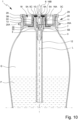
- embodiments without a collar 19 are also possible, which will be explained later, particularly with reference to Fig. 10 and 12 is still being discussed.
- the collar 19 forms an annular groove open downwards or in the direction of the container 3 for receiving the edge 3C of the container 3.
- valve plate 8 is friction-welded in the region of the collar 19 to a wall forming or delimiting the opening 3A of the container 3.
- the collar 19 surrounds the wall forming the opening 3A.
- a seal or a sealing ring may also be provided, which is preferably arranged in the collar 19 before the valve plate 8 is welded to the container 3, in particular to ensure a tight closure of the container 3.
- the container 3 preferably has a coupling portion 20.
- the coupling portion 20 is arranged in particular in a neck region 3B of the container 3 surrounding and/or forming the opening 3A.
- the coupling section 20 is preferably designed for the rotationally fixed coupling of the container 3 with a tool or holder 28 for or during friction welding of the valve disk 8 to the container 3. This is particularly the case in Figs. 11 and 12 shown.
- the coupling section 20 is formed by or comprises one or more coupling elements 20A projecting radially from the container 3 or the neck region 3B.
- the coupling elements 20A can be arranged uniformly distributed on the neck region 3B or container 3. It is also possible for the coupling section to comprise only one coupling element 20A extending collar-like around the container 3 or the opening 3A.
- the wall of the container 3 is preferably thicker or reinforced.
- a step or a projection is formed in the neck region 3B of the container 3 and/or the collar 19 of the valve disk 8, which allows easy centering or arrangement or initial guidance of the valve disk 8 in the opening 3A before friction welding.
- the weld seam or welded joint formed during friction welding between the container 3 or the neck region 3B and the valve plate 8 preferably has an axial extension of at least 3 mm, in particular 5 mm or more. This ensures a secure attachment of the valve plate 8 to the container 3.
- the propellant gas is preferably introduced under high pressure into the (fully assembled and preferably already filled with fluid F) dispensing device 1, in which the fastening part 11 is firmly connected to the valve plate 8 and the valve plate 8 is firmly connected to the container 3. Due to the high pressure, the propellant gas G deforms the seal 10, so that a gap forms between the seal 10 and the section 16B. The propellant gas G can now first pass between the valve element 6 and the section 16B and then through the gap between the seal 10 and the section 16B. The propellant gas G then passes through channels 5C, which are formed between the ribs of the valve housing 5, which form the shoulder 5A, and the section 16A, past the valve housing 5 and the fastening part 11 into the interior of the container 3. The path of the propellant gas G when filling the dispensing device 1 is shown in Fig. 2 indicated by an arrow on the left side.
- Fig. 5 and 6 show a proposed dispensing device 1 according to a second embodiment.
- Fig. 7 and 8 the fastening part 11 and the valve plate 8 according to the second embodiment are shown.
- the second embodiment differs from the first embodiment by a different design of the fastening part 11 and the valve plate 8.
- the fastening part 11 is preferably cap-shaped.
- a hollow cylindrical, sleeve-like, or ring-like section of the fastening part 11 is adjoined at the end by an end wall 21 extending transversely, in particular perpendicularly, to the axis L.
- the end wall 21 preferably has an opening 22 for the valve 4 or valve element 6, which is preferably arranged centrally or centrally.
- the coupling section 13 has recesses 14 in the form of elongated or axially extending radial indentations in the outer edge of the fastening part 11 or its cylindrical section, or is formed by them.
- recesses 14 in the form of elongated or axially extending radial indentations in the outer edge of the fastening part 11 or its cylindrical section, or is formed by them.
- radial projections are also conceivable here, for example, radial projections.
- the recesses 14 or indentations are preferably arranged symmetrically on the fastening part 11.
- the fastening part 11 or the coupling section 13 has six recesses 14.
- other solutions are also possible here.
- the fastening part 11 is arranged on the outside of the valve plate 8.
- valve 4 with the valve housing 5, the valve element 6, the return element 7, and the seal 10 is preferably arranged in the associated receptacle 9 of the valve plate 8, in particular inserted into the receptacle from the outside or top side of the valve plate 8.
- the fastening part 11 is preferably pushed over the valve 4 or valve housing 5.
- valve 4 or valve housing 5 is preferably secured or fastened to the valve plate 8.
- the securing or fastening of the valve 4 or valve housing 5 to the valve plate 8 is preferably carried out by a material-to-material connection, in particular welding, of the fastening part 11 to the valve plate 8.
- the fastening part 11 is friction welded to the valve plate 8.
- valve plate 8 according to the second embodiment differs from the valve plate 8 according to the first embodiment preferably (mainly) in the design or construction of the receptacle 9 and/or the receptacle space 16.
- the receptacle 9 or the receptacle space 16 is at least substantially cylindrical.
- the receptacle space 16 or the receptacle 9 is preferably not delimited on one side by a (wall) section 16B of the valve disk 8 extending transversely to the longitudinal axis L.
- the function of section 16B is preferably assumed by the cover surface 21 of the fastening part 11.
- a support surface 23 or a projection is formed or arranged in the receptacle 9 or the receiving space 16. Due to the support surface 23, the diameter of the receiving space 16 is preferably reduced in the region of the support surface 23.
- the support surface 23 can be formed by several individual elements arranged in the receiving space 16.
- the support surface 23 is designed as a one-piece circumferential ring or axial stop for the shoulder 5A of the valve housing 5.
- the support surface 23 is preferably designed to hold the valve 4 or valve housing 5 in an axially positive manner in the receptacle 9 or the receptacle space 16 or to prevent the valve 4 or valve housing 5 from slipping through the receptacle 9 or the receptacle space 16.
- the support surface 23 is preferably designed to bear against the shoulder 5A of the valve housing 5 or is associated with the shoulder 5A of the valve housing 5.
- the support surface 23 preferably forms a stop.
- the support surface 23 preferably at least partially assumes the function of the fastening part 11 in the first embodiment, which holds the valve housing 5 in a form-fitting manner by supporting it on the shoulder 5A of the valve housing 5 in the receptacle 9 or the receptacle space 16.
- the fastening part 11 preferably has the welding region 15 on an inner side or on an inner edge of the cylindrical section.
- the welding region 15 preferably projects radially inward from the fastening part 11 or cylindrical section.
- the welding region 15 in the fastening part 11 according to the second embodiment is not arranged or formed axially offset or displaced relative to the coupling section 13 on the fastening part 11.
- the welding region 15 is preferably arranged on an inner side or inner surface of the fastening part 11 or a cylindrical portion of the fastening part 11.
- the inner side of the fastening part 11 is preferably welded to the wall section 16A, which forms the inner boundary or an inner wall of the annular space 18.
- the inner diameter of the fastening part 11 or welding area 15 and the (outer) diameter of the section 16A are preferably matched to one another such that the inner diameter of the fastening part 11 or welding area 15 is somewhat smaller, in particular by at least 0.1 mm and/or at most 2 mm, than the (outer) diameter of the section 16A, so that the fastening part 11 can be friction welded to the section 16A.
- the fastening part 11 can therefore preferably not be pushed over the section 16A or the receiving space 16 without deformation.
- the "too small" diameter of the fastening part 11 has the effect, in particular, that when the fastening part 11 rotates or when the fastening part 11 is friction-welded to the valve plate 8, the welding area 15 is melted or plasticized by frictional heat, so that the fastening part 11 is deformable at least in the welding area 15 and can be pushed over the receiving space 16, wherein the fastening part 11 is integrally connected to the valve plate 8 or its wall section 16A.
- the fastening part 11 is laser welded or ultrasonically welded to the valve plate 8 instead of friction welded.
- the fastening part 11 preferably has a first section 24 and a second section 25.
- the first section 24 is preferably cylindrical or hollow-cylindrical. However, the first section 24 can also be slightly conical. In this way, a clamping effect can be achieved when the fastening part 11 or the first section 24 is inserted into the receiving space 16 of the valve plate 8.
- the second section 25 preferably projects radially from the first section 24 and/or is arranged at least substantially at right angles to the first section 24.
- the second portion 25 is preferably arranged at an axial end of the fastening part 11.
- the second section 25 is designed to bear against the lower or radially extending boundary surface of the annular space 18 of the valve disk 8.
- the fastening part 11, in particular the second section 25, preferably has the welding region 15.
- the welding region 15 is ring-shaped and/or arranged coaxially with the first section 24.
- the welding region 15 it is possible for the welding region 15 to be formed by several non-contiguous, in particular small-area and/or point-like, elevations, so that no continuous weld seam 26 is formed during welding, but only point-like weld connections.
- the welding area 15 is rectangular in cross section.
- the welding area 15 can also be Fig. 9 B shown, have a triangular cross-section.
- other shapes of the cross-section of the welding area 15 are also possible, for example round, in particular semicircular, or other cross-sections.
- the welding area 15 is designed, in particular, to plasticize during laser welding or ultrasonic welding and thus to form a weld seam 26 between the fastening part 11 and the valve plate 8. It is particularly possible for the fastening part 11 welded to the valve plate 8 not to bear against the valve plate 8 over its entire surface, but preferably only in the area of the weld seam 26. This makes it possible to compensate for unevenness and/or tolerances of the valve plate 8 and/or the fastening part 11. In particular, this reliably ensures that the seal 10 is firmly clamped and/or the valve housing 5 sits in the valve plate 8 without play or is clamped between the valve plate 8 and the fastening part 11 without play.
- the welding region 15 preferably forms an elevation or a material excess of the second section 25.
- the (axial) thickness or height of the welding region 15 is preferably more than 0.2 mm and/or less than 1.2 mm, in particular approximately 0.8 mm. This preferably compensates for unevenness of the valve disk 8 and/or the fastening part 11 and/or axial tolerances.
- the valve 4 is preferably first inserted into the receptacle 9 or the receiving space 16, in particular from the inside of the valve plate 8. Subsequently, the fastening part 11 is preferably also inserted into the receptacle 9 or the receiving space 16, so that the valve 4 is arranged between the valve plate 8 and the fastening part 11, in particular clamped therebetween.
- valve plate 8, the valve 4 or valve housing 5 and the fastening part 11 are preferably dimensioned or matched to one another in such a way that the second section 25 or the welding area 15 rests against an underside of the valve plate 8, in particular flatly, when the fastening part 11 is completely inserted into the receptacle 9 or the receiving space 16 and/or the valve 4 is clamped between the valve plate 8 and the fastening part 11.
- the valve disk 8 is made of a laser-absorbing and/or dark, in particular black, material, and the fastening part 11 or at least the second section 25 is made of a transparent, in particular laser-transparent, material, so that the valve disk 8 can be irradiated with a laser through the fastening part 11 to create the welded connection with the fastening part 11.
- the laser beam can therefore preferably pass through the fastening part 11 without being absorbed.
- a laser transmission welding process or an ultrasonic welding process is preferably used.
- the valve plate 8 or its inner side is irradiated with a laser through the fastening part 11.
- the material is heated as a result.
- the laser beam passes through the welding area 15 and/or the laser beam is directed onto the welding area 15. Due to the absorption in the valve plate 8, the material of the valve plate 8 is heated and thus melted or plasticized. This occurs in particular in the immediate vicinity of or at the contact surface with the welding area 15. Heat conduction processes preferably also heat and thus melt or plasticize the welding area 15, so that a weld seam 26 is created between the valve plate 8 and the fastening part 11 and the valve plate 8 and the fastening part 11 are joined together in a materially bonded manner.
- valve plate 8 and the fastening part 11 are preferably each made of a plastic, in particular PET.
- a high-power diode laser preferably with a wavelength of more than 900 nm and/or less than 1100 nm, or a solid-state laser, in particular a fiber laser or Nd:YAG laser, preferably with a wavelength of more than 1060 nm and/or less than 1090 nm, is used for laser welding.
- valve disk 8 is laser-welded or ultrasonically welded to the fastening part 11 and that the valve arrangement 2 thus provided is friction-welded to the container 3, as described above. It is also possible for the valve disk 8 to be collarless or to have no collar 19 for the edge 3C of the container 3. This is particularly the case in the Fig. 10 and 12 In this case, the valve disk 8 preferably ends (axially) flush with the container 3 or the edge 3C of the container.
- valve plate 8 or the valve arrangement 2 is first inserted into the container 3.
- the valve plate 8 can be inserted in a defined position or rotational position relative to the container 3.
- valve assembly 2 When connecting the valve assembly 2 to the container 3, the valve assembly 2 is preferably held with a first holder or tool 27 and the container 3 is preferably held with a second holder or tool 28. This is shown schematically in the Figs. 11 and 12 shown.
- the coupling element 20A is designed as a collar or radially projecting element surrounding the container 3 or the opening 3A.
- the coupling element 20A has one or more engagement elements, in particular opposing engagement elements, which are designed to engage with the holder 28.
- the engagement elements are formed by recesses.
- the container 3 and the valve arrangement 2 are moved axially towards each other and simultaneously rotated relative to each other about the axis L.
- one of the parts, preferably the container 3, is held in a fixed position and the other part, preferably the valve arrangement 2, is rotated relative thereto about the axis L.
- valve plate 8 is preferably held and/or turned or rotated by means of a tool 27 which positively engages the valve plate 8 or its coupling device 17 and/or holds or grips the valve plate 8 at the coupling elements 17A.
- valve plate 8 and the container 3 are preferably moved axially toward each other until the valve plate 8 has reached a defined end position or axial position relative to the container 3.
- the valve plate 8 is preferably designed without a collar or the valve plate 8 does not have a collar 19.
- valve disk 8 is axially flush with the container 3 or its edge 3C in the end position or defined axial position.
- other solutions are also possible here.
- a flush seal allows for a simple and reliable inspection of the connection between the container 3 and the valve plate 8 or the valve assembly 2, since the flush seal or defined seating of the valve plate 8 indicates a correct or flawless connection. In particular, it is an indication of a faulty connection or welded joint if, after the connection has been established, the (collarless) valve plate 8 is not axially flush with the edge 3C of the container.
- a defined number of revolutions for example, exactly 12 revolutions, are performed during friction welding of the container 3 to the valve plate 8. This ensures an efficient, fast, and reproducible connection or welding of the valve assembly 2 to the container 3.
- a particularly ring-like and/or radial welding surface 29 is preferably created.
- the welding surface is particularly the area in which the material of the container 3 and/or the valve plate 8 is plasticized during friction welding and thus forms the material-locking connection or weld.
- the width of the welding surface 29 or the extension of the welding surface 29 in the radial direction is preferably more than 0.1 mm and/or less than 0.5 mm, in particular approximately 0.3 mm.
- the length of the weld seam 29 or the extension of the weld seam 29 in the axial direction is preferably more than 0.5 mm, in particular more than 1 mm, and/or less than 2 mm, in particular less than 1.5 mm.
- the dispensing device 1 preferably has a dispensing head (not shown in the figures) for dispensing the fluid F.
- the edge 3C is preferably thickened and/or collar- or flange-like.
- the edge 3C protrudes, in particular, radially from the neck region 3B.
- the dispensing head is positively connected to or attached to the edge 3C.
- the dispensing head can be supported on the edge 3C and/or the valve plate 8, in particular if the valve plate 8 is flush with the edge 3C.
- the coupling element 20A can be omitted or formed by the (thickened) edge 3C.
- the edge 3C then preferably has the features described above for the coupling element 20A.
Landscapes
- Engineering & Computer Science (AREA)
- Mechanical Engineering (AREA)
- Chemical & Material Sciences (AREA)
- Dispersion Chemistry (AREA)
- Containers And Packaging Bodies Having A Special Means To Remove Contents (AREA)
- Feeding, Discharge, Calcimining, Fusing, And Gas-Generation Devices (AREA)
- Valve Housings (AREA)
- Nozzles (AREA)
Applications Claiming Priority (4)
| Application Number | Priority Date | Filing Date | Title |
|---|---|---|---|
| DE102018002130 | 2018-03-16 | ||
| DE102018003741.0A DE102018003741B4 (de) | 2018-03-16 | 2018-05-04 | Abgabevorrichtung mit reibverschweißtem Ventilteller |
| PCT/EP2019/052281 WO2019174809A1 (fr) | 2018-03-16 | 2019-01-30 | Système de soupapes et dispositif d'évacuation |
| EP19706386.0A EP3765384B1 (fr) | 2018-03-16 | 2019-01-30 | Système de soupapes et dispositif d'évacuation |
Related Parent Applications (2)
| Application Number | Title | Priority Date | Filing Date |
|---|---|---|---|
| EP19706386.0A Division EP3765384B1 (fr) | 2018-03-16 | 2019-01-30 | Système de soupapes et dispositif d'évacuation |
| EP19706386.0A Division-Into EP3765384B1 (fr) | 2018-03-16 | 2019-01-30 | Système de soupapes et dispositif d'évacuation |
Publications (2)
| Publication Number | Publication Date |
|---|---|
| EP4520509A2 true EP4520509A2 (fr) | 2025-03-12 |
| EP4520509A3 EP4520509A3 (fr) | 2025-05-07 |
Family
ID=67774084
Family Applications (2)
| Application Number | Title | Priority Date | Filing Date |
|---|---|---|---|
| EP24220062.4A Pending EP4520509A3 (fr) | 2018-03-16 | 2019-01-30 | Ensemble soupape et dispositif de distribution |
| EP19706386.0A Active EP3765384B1 (fr) | 2018-03-16 | 2019-01-30 | Système de soupapes et dispositif d'évacuation |
Family Applications After (1)
| Application Number | Title | Priority Date | Filing Date |
|---|---|---|---|
| EP19706386.0A Active EP3765384B1 (fr) | 2018-03-16 | 2019-01-30 | Système de soupapes et dispositif d'évacuation |
Country Status (9)
| Country | Link |
|---|---|
| US (2) | US11299338B2 (fr) |
| EP (2) | EP4520509A3 (fr) |
| JP (1) | JP2021518520A (fr) |
| CN (2) | CN116331670B (fr) |
| BR (1) | BR112020018381A2 (fr) |
| CA (1) | CA3092117A1 (fr) |
| DE (1) | DE102018003741B4 (fr) |
| PL (1) | PL3765384T3 (fr) |
| WO (1) | WO2019174809A1 (fr) |
Families Citing this family (8)
| Publication number | Priority date | Publication date | Assignee | Title |
|---|---|---|---|---|
| EP3758647B1 (fr) * | 2018-02-26 | 2024-07-31 | Argenta Innovation Limited | Dispositif intra-ruminal |
| DE102018003741B4 (de) | 2018-03-16 | 2021-08-26 | Aptar Dortmund Gmbh | Abgabevorrichtung mit reibverschweißtem Ventilteller |
| FR3099144B1 (fr) * | 2019-07-24 | 2022-01-07 | Lindal France | Valve pour récipient sous pression |
| EP4190716A1 (fr) | 2019-07-24 | 2023-06-07 | Lindal France SAS | Coupelle de valve pour récipient sous pression |
| BE1027834B1 (nl) * | 2020-05-22 | 2021-07-02 | Altachem | Kogelgewrichtklep |
| BE1028731B1 (nl) * | 2020-10-23 | 2022-05-23 | Gojara Bvba | Mechanische bevestigingsmiddelen voor opname van een ventielbehuizing, voorvorm, container en spuitbus omvattend de mechanische bevestigingsmiddelen |
| JP2022129862A (ja) * | 2021-02-25 | 2022-09-06 | キヤノン株式会社 | 液体吐出装置に液体を補充するための液体補充容器、および該液体補充容器を用いた再利用システム |
| DE102023109695A1 (de) * | 2023-04-18 | 2024-10-24 | Samson Aktiengesellschaft | Aufsatzvorrichtung für ein Stellventil und Stellventil mit der Aufsatzvorrichtung |
Citations (5)
| Publication number | Priority date | Publication date | Assignee | Title |
|---|---|---|---|---|
| WO1989008062A1 (fr) | 1988-03-04 | 1989-09-08 | Perfect-Valois Ventil Gmbh | Recipient aerosol |
| EP2832661A1 (fr) | 2013-07-31 | 2015-02-04 | Thomas GmbH | Fixation de soupape d'aérosol pour conteneur pressurisé comprenant une coupelle en plastique |
| EP2894114A1 (fr) | 2014-01-13 | 2015-07-15 | Thomas GmbH | Bloc de soupape pour récipient aérosol |
| WO2016202754A1 (fr) | 2015-06-16 | 2016-12-22 | Lindal France Sas | Procédé pour fabriquer une valve d'aérosol et valve d'aérosol |
| WO2017021038A1 (fr) | 2015-08-04 | 2017-02-09 | Coster Tecnologie Speciali S.P.A. | Coupelles de valve et récipients à utiliser dans des systèmes de distribution de milieu fluide |
Family Cites Families (18)
| Publication number | Priority date | Publication date | Assignee | Title |
|---|---|---|---|---|
| FR2441778A1 (fr) * | 1978-11-17 | 1980-06-13 | Aerosol Inventions Dev | Ensemble de distribution et remplissage pour recipient aerosol |
| GB2193260B (en) | 1986-01-30 | 1989-11-01 | Bespak Plc | Collapsible chamber metering valves |
| DE3886184D1 (de) | 1987-06-26 | 1994-01-20 | Werding Winfried J | Vorrichtung zur lagerung und kontrollierten abgabe von unter druck stehenden produkten und verfahren zu ihrer herstellung. |
| DE4427175A1 (de) * | 1994-08-01 | 1996-02-08 | Coster Tecnologie Speciali Spa | Baueinheit |
| US5573043A (en) * | 1994-12-23 | 1996-11-12 | Stoffel Seals Corporation | Closure cup for a pressure dispenser |
| WO1999007614A1 (fr) * | 1997-08-12 | 1999-02-18 | Veresk Biosystems Limited | Recipient |
| US20020156161A1 (en) | 2000-02-11 | 2002-10-24 | Reiko Koshida | Thermoplastic resin compositions for laser welding and articles formed therefrom |
| CA2397977A1 (fr) * | 2000-02-11 | 2001-08-16 | E.I. Du Pont De Nemours And Company | Compositions de resines thermoplastiques destinees au soudage par laser et articles formes a partir de ces compositions |
| EP1485309B1 (fr) | 2002-01-24 | 2009-11-18 | Rathor Ag | Soupape |
| JP4833608B2 (ja) * | 2005-08-05 | 2011-12-07 | 麒麟麦酒株式会社 | 密封容器 |
| US8286839B2 (en) * | 2008-08-12 | 2012-10-16 | Aptar Dortmund Gmbh | Dispensing device |
| CA2796898A1 (fr) * | 2010-04-20 | 2011-10-27 | Capnia, Inc. | Bouteille de gaz comprime a soupape integree |
| FR2973786B1 (fr) * | 2011-04-06 | 2014-07-04 | Valois Sas | Bague pour dispositif de distribution de produit fluide. |
| US9701430B2 (en) * | 2011-05-16 | 2017-07-11 | The Procter & Gamble Company | Components for aerosol dispenser |
| US10604332B2 (en) * | 2013-10-23 | 2020-03-31 | The Procter & Gamble Company | Aerosol container having valve cup with integral bag |
| EP2998241A1 (fr) * | 2014-09-18 | 2016-03-23 | Thomas GmbH | Fixation d'une soupape dans la coupelle d'un récipient aérosol |
| JP2018529587A (ja) | 2015-08-04 | 2018-10-11 | コスター テクノロジー スペシヤリ ソチエタ ペル アチオーニCoster Tecnologie Speciali S.P.A. | 流体媒体分注システムで使用するためのバルブカップおよび容器 |
| DE102018003741B4 (de) | 2018-03-16 | 2021-08-26 | Aptar Dortmund Gmbh | Abgabevorrichtung mit reibverschweißtem Ventilteller |
-
2018
- 2018-05-04 DE DE102018003741.0A patent/DE102018003741B4/de active Active
-
2019
- 2019-01-30 BR BR112020018381-4A patent/BR112020018381A2/pt not_active Application Discontinuation
- 2019-01-30 PL PL19706386.0T patent/PL3765384T3/pl unknown
- 2019-01-30 US US16/978,363 patent/US11299338B2/en active Active
- 2019-01-30 CN CN202310260963.4A patent/CN116331670B/zh active Active
- 2019-01-30 WO PCT/EP2019/052281 patent/WO2019174809A1/fr not_active Ceased
- 2019-01-30 EP EP24220062.4A patent/EP4520509A3/fr active Pending
- 2019-01-30 CA CA3092117A patent/CA3092117A1/fr active Pending
- 2019-01-30 JP JP2020572603A patent/JP2021518520A/ja active Pending
- 2019-01-30 EP EP19706386.0A patent/EP3765384B1/fr active Active
- 2019-01-30 CN CN201980016850.1A patent/CN111801284B/zh active Active
-
2022
- 2022-04-07 US US17/715,446 patent/US11845605B2/en active Active
Patent Citations (5)
| Publication number | Priority date | Publication date | Assignee | Title |
|---|---|---|---|---|
| WO1989008062A1 (fr) | 1988-03-04 | 1989-09-08 | Perfect-Valois Ventil Gmbh | Recipient aerosol |
| EP2832661A1 (fr) | 2013-07-31 | 2015-02-04 | Thomas GmbH | Fixation de soupape d'aérosol pour conteneur pressurisé comprenant une coupelle en plastique |
| EP2894114A1 (fr) | 2014-01-13 | 2015-07-15 | Thomas GmbH | Bloc de soupape pour récipient aérosol |
| WO2016202754A1 (fr) | 2015-06-16 | 2016-12-22 | Lindal France Sas | Procédé pour fabriquer une valve d'aérosol et valve d'aérosol |
| WO2017021038A1 (fr) | 2015-08-04 | 2017-02-09 | Coster Tecnologie Speciali S.P.A. | Coupelles de valve et récipients à utiliser dans des systèmes de distribution de milieu fluide |
Also Published As
| Publication number | Publication date |
|---|---|
| CN116331670A (zh) | 2023-06-27 |
| CN116331670B (zh) | 2026-03-13 |
| DE102018003741A1 (de) | 2019-09-19 |
| EP3765384A1 (fr) | 2021-01-20 |
| PL3765384T3 (pl) | 2025-05-26 |
| BR112020018381A2 (pt) | 2020-12-29 |
| EP3765384C0 (fr) | 2025-01-22 |
| EP3765384B1 (fr) | 2025-01-22 |
| CA3092117A1 (fr) | 2019-09-19 |
| US20220227570A1 (en) | 2022-07-21 |
| WO2019174809A1 (fr) | 2019-09-19 |
| JP2021518520A (ja) | 2021-08-02 |
| CN111801284B (zh) | 2023-03-10 |
| US11299338B2 (en) | 2022-04-12 |
| EP4520509A3 (fr) | 2025-05-07 |
| US20210002062A1 (en) | 2021-01-07 |
| DE102018003741B4 (de) | 2021-08-26 |
| US11845605B2 (en) | 2023-12-19 |
| CN111801284A (zh) | 2020-10-20 |
Similar Documents
| Publication | Publication Date | Title |
|---|---|---|
| EP3765384B1 (fr) | Système de soupapes et dispositif d'évacuation | |
| DE102014113392B4 (de) | Verschlussvorrichtung für einen Behälter | |
| DE69201671T2 (de) | Abdichtaufsätze für Filterelemente. | |
| EP1986926B1 (fr) | Seringue | |
| EP2478961B1 (fr) | Dispositif de fermeture universel | |
| DE102007035728B4 (de) | Vorrichtung zum Öffnen und Verschließen eines Getränkebehälters | |
| EP0106280A1 (fr) | Ensemble de valve pour récipients aérosol à deux compartiments | |
| EP1976764A1 (fr) | Systeme d'ouverture refermable realise a partir d'un produit semi-fini et procede pour son montage | |
| EP2873465A1 (fr) | Piston pour distribuer un fluide d'une cartouche | |
| WO2015165945A1 (fr) | Procédé et dispositif d'activation thermique de gaines d'emballage | |
| EP3256396B1 (fr) | Dispositif de fermeture pour un récipient | |
| EP3730101B1 (fr) | Capuchon de protection ventilé pour un distributeur de liquide | |
| DE102004044288A1 (de) | Vorrichtung zur Verbindung eines rohrförmigen Teils, insbesondere einer Kanüle, mit dem Inneren einer Flasche oder dergleichen | |
| EP2697151B1 (fr) | Élément de remplissage | |
| DE3122982A1 (de) | Verschlussdeckel fuer mit einem randwulst versehene behaelter | |
| DE2356796A1 (de) | Hohlkoerper und verfahren zu dessen herstellung | |
| DE60001189T2 (de) | Ausgabekopf für eine Vorrichtung von der Art mit Ventil oder Pumpe | |
| CH627703A5 (en) | Frangible container closure, method for its manufacture, and use | |
| DE2918429C2 (de) | Vorrichtung zum Verschließen eines Behälters | |
| DE102019211860A1 (de) | Werkzeuganordnung für den Herstellprozess von Fixierpunkten | |
| DE2449516C3 (de) | Flaschenverschluß mit einem Ausgießkörper | |
| DE2034133B2 (de) | Verfahren zum anbringen eines anschlusstutzens an eine wand sowie anschlusstutzen zum durchfuehren des verfahrens | |
| EP2780249B1 (fr) | Fermeture étanche à vis | |
| AT515924B1 (de) | Verfahren zur Herstellung eines Zylindergehäuses in Leichtbau-Mischbauweise | |
| DE2730317C3 (de) | Kombiniertes Einlaß-Auslaßventil für die Sterilisierung einer Vakuumsaugflasche für medizinische Zwecke |
Legal Events
| Date | Code | Title | Description |
|---|---|---|---|
| PUAI | Public reference made under article 153(3) epc to a published international application that has entered the european phase |
Free format text: ORIGINAL CODE: 0009012 |
|
| STAA | Information on the status of an ep patent application or granted ep patent |
Free format text: STATUS: THE APPLICATION HAS BEEN PUBLISHED |
|
| AC | Divisional application: reference to earlier application |
Ref document number: 3765384 Country of ref document: EP Kind code of ref document: P |
|
| AK | Designated contracting states |
Kind code of ref document: A2 Designated state(s): AL AT BE BG CH CY CZ DE DK EE ES FI FR GB GR HR HU IE IS IT LI LT LU LV MC MK MT NL NO PL PT RO RS SE SI SK SM TR |
|
| REG | Reference to a national code |
Ref country code: DE Ref legal event code: R079 Free format text: PREVIOUS MAIN CLASS: B29C0065080000 Ipc: B65D0083380000 |
|
| PUAL | Search report despatched |
Free format text: ORIGINAL CODE: 0009013 |
|
| AK | Designated contracting states |
Kind code of ref document: A3 Designated state(s): AL AT BE BG CH CY CZ DE DK EE ES FI FR GB GR HR HU IE IS IT LI LT LU LV MC MK MT NL NO PL PT RO RS SE SI SK SM TR |
|
| RIC1 | Information provided on ipc code assigned before grant |
Ipc: B29L 31/00 20060101ALI20250403BHEP Ipc: B29C 65/00 20060101ALI20250403BHEP Ipc: B29C 65/16 20060101ALI20250403BHEP Ipc: B29C 65/08 20060101ALI20250403BHEP Ipc: B29C 65/06 20060101ALI20250403BHEP Ipc: B23K 20/12 20060101ALI20250403BHEP Ipc: B23K 20/10 20060101ALI20250403BHEP Ipc: B65D 83/48 20060101ALI20250403BHEP Ipc: B65D 83/38 20250101AFI20250403BHEP |
|
| STAA | Information on the status of an ep patent application or granted ep patent |
Free format text: STATUS: REQUEST FOR EXAMINATION WAS MADE |
|
| 17P | Request for examination filed |
Effective date: 20251031 |