EP4520548A1 - Reifen - Google Patents
Reifen Download PDFInfo
- Publication number
- EP4520548A1 EP4520548A1 EP24193691.3A EP24193691A EP4520548A1 EP 4520548 A1 EP4520548 A1 EP 4520548A1 EP 24193691 A EP24193691 A EP 24193691A EP 4520548 A1 EP4520548 A1 EP 4520548A1
- Authority
- EP
- European Patent Office
- Prior art keywords
- tire
- axial
- axial grooves
- pitch
- grooves
- Prior art date
- Legal status (The legal status is an assumption and is not a legal conclusion. Google has not performed a legal analysis and makes no representation as to the accuracy of the status listed.)
- Granted
Links
Images


Classifications
-
- B—PERFORMING OPERATIONS; TRANSPORTING
- B60—VEHICLES IN GENERAL
- B60C—VEHICLE TYRES; TYRE INFLATION; TYRE CHANGING; CONNECTING VALVES TO INFLATABLE ELASTIC BODIES IN GENERAL; DEVICES OR ARRANGEMENTS RELATED TO TYRES
- B60C11/00—Tyre tread bands; Tread patterns; Anti-skid inserts
- B60C11/03—Tread patterns
- B60C11/0318—Tread patterns irregular patterns with particular pitch sequence
-
- B—PERFORMING OPERATIONS; TRANSPORTING
- B60—VEHICLES IN GENERAL
- B60C—VEHICLE TYRES; TYRE INFLATION; TYRE CHANGING; CONNECTING VALVES TO INFLATABLE ELASTIC BODIES IN GENERAL; DEVICES OR ARRANGEMENTS RELATED TO TYRES
- B60C11/00—Tyre tread bands; Tread patterns; Anti-skid inserts
- B60C11/03—Tread patterns
- B60C11/0302—Tread patterns directional pattern, i.e. with main rolling direction
-
- B—PERFORMING OPERATIONS; TRANSPORTING
- B60—VEHICLES IN GENERAL
- B60C—VEHICLE TYRES; TYRE INFLATION; TYRE CHANGING; CONNECTING VALVES TO INFLATABLE ELASTIC BODIES IN GENERAL; DEVICES OR ARRANGEMENTS RELATED TO TYRES
- B60C11/00—Tyre tread bands; Tread patterns; Anti-skid inserts
- B60C11/03—Tread patterns
- B60C11/0306—Patterns comprising block rows or discontinuous ribs
-
- B—PERFORMING OPERATIONS; TRANSPORTING
- B60—VEHICLES IN GENERAL
- B60C—VEHICLE TYRES; TYRE INFLATION; TYRE CHANGING; CONNECTING VALVES TO INFLATABLE ELASTIC BODIES IN GENERAL; DEVICES OR ARRANGEMENTS RELATED TO TYRES
- B60C11/00—Tyre tread bands; Tread patterns; Anti-skid inserts
- B60C11/03—Tread patterns
- B60C11/0327—Tread patterns characterised by special properties of the tread pattern
-
- B—PERFORMING OPERATIONS; TRANSPORTING
- B60—VEHICLES IN GENERAL
- B60C—VEHICLE TYRES; TYRE INFLATION; TYRE CHANGING; CONNECTING VALVES TO INFLATABLE ELASTIC BODIES IN GENERAL; DEVICES OR ARRANGEMENTS RELATED TO TYRES
- B60C11/00—Tyre tread bands; Tread patterns; Anti-skid inserts
- B60C11/03—Tread patterns
- B60C11/12—Tread patterns characterised by the use of narrow slits or incisions, e.g. sipes
-
- B—PERFORMING OPERATIONS; TRANSPORTING
- B60—VEHICLES IN GENERAL
- B60C—VEHICLE TYRES; TYRE INFLATION; TYRE CHANGING; CONNECTING VALVES TO INFLATABLE ELASTIC BODIES IN GENERAL; DEVICES OR ARRANGEMENTS RELATED TO TYRES
- B60C11/00—Tyre tread bands; Tread patterns; Anti-skid inserts
- B60C11/03—Tread patterns
- B60C2011/0337—Tread patterns characterised by particular design features of the pattern
- B60C2011/0339—Grooves
- B60C2011/0341—Circumferential grooves
-
- B—PERFORMING OPERATIONS; TRANSPORTING
- B60—VEHICLES IN GENERAL
- B60C—VEHICLE TYRES; TYRE INFLATION; TYRE CHANGING; CONNECTING VALVES TO INFLATABLE ELASTIC BODIES IN GENERAL; DEVICES OR ARRANGEMENTS RELATED TO TYRES
- B60C11/00—Tyre tread bands; Tread patterns; Anti-skid inserts
- B60C11/03—Tread patterns
- B60C2011/0337—Tread patterns characterised by particular design features of the pattern
- B60C2011/0339—Grooves
- B60C2011/0358—Lateral grooves, i.e. having an angle of 45 to 90 degees to the equatorial plane
- B60C2011/0372—Lateral grooves, i.e. having an angle of 45 to 90 degees to the equatorial plane with particular inclination angles
Definitions
- the present invention relates to a tire.
- Japanese unexamined patent application publication No. 2022-122121 has proposed a tire in which uneven wear resistance performance and noise performance are improved by specifying the pitch number of axial grooves.
- the present invention was made in view of the above, and a primary object thereof is to provide a tire capable of improving the noise performance while maintaining the steering stability.
- the present invention is a tire having a tread portion, wherein the tread portion including:
- the tire of the present invention improves the noise performance while maintaining the steering stability by having the configuration described above.
- FIG. 1 is a development view of a tread portion 2 of a tire 1 of the present embodiment in a standard state.
- the tire 1 of the present embodiment is used as a pneumatic tire for passenger cars, for example.
- the present invention may also be implemented as a motorcycle tire or a heavy-duty tire.
- the term "standard state” refers to a state in which the tire is mounted on a standard rim, inflated to a standard inner pressure, and loaded with no tire load.
- the standard state means a standard use state according to the purpose of use of the tire and being loaded with no tire load.
- the dimensions of various parts of the tire are values measured in the standard state unless otherwise noted. Further, known methods can be appropriately used for measuring the above dimensions unless otherwise specified in the present specification.
- standard rim refers to a wheel rim specified for the concerned tire by a standard included in a standardization system on which the tire is based, for example, the "normal wheel rim” in JATMA, "Design Rim” in TRA, and “Measuring Rim” in ETRTO.
- standard inner pressure refers to air pressure specified for the concerned tire by a standard included in a standardization system on which the tire is based, for example, the maximum air pressure in JATMA, the maximum value listed in the "TIRE LOAD LIMITS AT VARIOUS COLD INFLATION PRESSURES" table in TRA, and "INFLATION PRESSURE” in ETRTO.
- Tread portion 2 includes two tread edges (Te) and a ground contacting surface demarcated between them.
- the tread edges (Te) are the axially outermost ground contacting positions of the tire 1 when the tire 1 in the standard state is in contact with a flat surface with zero camber angle by being loaded with 70% of a standard tire load.
- standard tire load refers to a tire load specified for the concerned tire by a standard included in a standardization system on which the tire is based, for example, the “maximum load capacity” in JATMA, maximum value listed in “TIRE LOAD LIMITS AT VARIOUS COLD INFLATION PRESSURES" table in TRA, and "LOAD CAPACITY” in ETRTO.
- standard tire load refers to the maximum load that can be applied to the tire in accordance with the above standards.
- the tread portion 2 includes a plurality of circumferential grooves 3 extending continuously in the tire circumferential direction between two tread edges (Te), and a plurality of land regions 4 demarcated by these circumferential grooves 3.
- the circumferential grooves 3 in the present embodiment include two crown circumferential grooves 5 and two shoulder circumferential grooves 6.
- the two crown circumferential grooves 5 are arranged so as to sandwich the tire equator (C) therebetween.
- the shoulder circumferential grooves 6 are arranged so that one shoulder circumferential groove 6 is located between the crown circumferential groove 5 and the tread edge (Te) in each axial half of the tread portion 2. Therefore, the two shoulder circumferential grooves 6 are arranged so as to sandwich the tire equator (C) and the two crown circumferential grooves 5 therebetween.
- Each of the circumferential grooves 3 has a groove width W1 of 3.0 mm or more, for example, in the range from 3.0% to 6.0% of a tread width TW.
- the tread width TW corresponds to the distance in the tire axial direction from one tread edge (Te) to the other tread edge (Te) of the tire in the standard state. It is preferred that each of the circumferential grooves 3 has a depth in the range from 5 to 10 mm, for example.
- the land regions 4 include first land regions 7 and second land regions 8. In each axial half of the tread portion 2, the first land region 7 and the second land region 8 are adjacent to each other. In each axial half of the tread portion 2 in the present embodiment, the first land region 7 is demarcated between the crown circumferential groove 5 and the shoulder circumferential groove 6. The second land regions 8 is demarcated axially outside the shoulder circumferential groove 6 and includes the tread edge (Te) in each axial half of the tread portion 2 in the present embodiment. Thereby, a pair of the first land region 7 and the second land region 8 is arranged on each side in the tire axial direction in the present embodiment. In addition to these land regions, the land regions 4 in the present embodiment further includes a third land region 9 on the tire equator (C). The third land region 9 has substantially the same configuration as the first land regions 7 described below.
- FIG. 2 shows an enlarged view of one of the first land regions 7 and one of the second land regions 8 adjacent thereto.
- each of the first land regions 7 is provided with a plurality of first axial grooves 11.
- Each of the first axial grooves 11 completely crosses a ground contacting surface (7s) of each of the first land regions 7 in the tire axial direction.
- each of the second land regions 8 is provided with a plurality of second axial grooves 12.
- Each of the second axial grooves 12 completely crosses a ground contacting surface (8s) of each of the second land regions 8 in the tire axial direction.
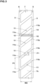
- FIG. 3 shows an enlarged view of one of the first land regions 7.
- each of the first axial grooves 11 includes a first end (11a) on one side (the shoulder circumferential groove 6 side in the present embodiment) in the tire axial direction and a second end (11b) on the other side (the crown circumferential groove 5 side in the present embodiment) in the tire axial direction.
- the first axial grooves 11 are arranged in a first arrangement described below over one tire circumference, i.e., over the entire circumference of the tire.
- the first axial grooves 11 are arranged at the same intervals or different intervals so that the number (a) of types of a first pitch P1, which is the distance in the tire circumferential direction between the first axial grooves 11 adjacent to each other in the tire circumferential direction, is one or more over the entire circumference of the tire.
- the term “pitch” means the distance in the tire circumferential direction between the groove centerlines of two axial grooves adjacent to each other in the tire circumferential direction. Further, when the two adjacent lateral grooves are non-parallel, the distance means the average distance in the tire circumferential direction weighted by the length of the axial grooves. In other words, when two axial grooves are observed, their arrangement determines a single pitch value.
- the first axial grooves 11 are arranged so that the first pitch P1 has the number (a) of 1 or more over the entire circumference of the tire.
- the number (a) is 1 in the present embodiment. That is, the first axial grooves 11 are arranged at equal intervals in the tire circumferential direction.
- the present invention is not limited to such a mode.
- the first end (11a) of one of the two first axial grooves 11 is located at the same position in the tire circumferential direction as the second end (11b) of the other first axial groove 11.
- this configuration means that 80% or more of the first axial grooves 11 provided in the first land regions 7 each have the first end (11a) located at the same position in the tire circumferential direction as the second end (11b) of another first axial groove 11.
- 90% or more of the first axial grooves 11, and in a more preferred embodiment, all of the first axial grooves 11, have the first ends (11a) and the second ends (11b) in the above arrangement.
- the first end (11a) and the second end (11b) are at the same position in the tire circumferential direction" at least includes an aspect in which, in a plan view of the tread, a region 14 (shaded in FIG. 3 in order to aid understanding) obtained by extending parallel to the tire axial direction an opening 13 open to the circumferential groove 3 (the shoulder circumferential groove 6 in FIG. 3 ) at the first end (11a) of one of the first axial grooves 11 overlaps with an opening 15 open to the circumferential groove 3 (the crown circumferential groove 5 in FIG. 3 ) at the second end (11b) of the other first axial groove 11.
- the case in which the distance between them in the tire circumferential direction is 5% or less of the first pitch P1 of the pair of the first axial grooves 11 is considered to meet the feature that "the first end (11a) and the second end (11b) are located at the same position in the tire circumferential direction.”
- the second axial grooves 12 of the present invention are arranged in a second arrangement, which will be described below, over the entire circumference of the tire.
- the second axial grooves 12 are arranged at different intervals so that the number (b) of types of a second pitch P2, which is the distance in the tire circumferential direction between the second axial grooves 12 adjacent to each other in the tire circumferential direction, is two or more over the entire circumference of the tire.
- the number (b) of types of the second pitch P2 is greater than the number (a) of types of the first pitch P1.
- the tire 1 of the present invention improves the noise performance while maintaining the steering stability.
- the reasons for this are as follows.
- pitch noise has been known as a type of noise that occurs during running.
- One of the causes of the pitch noise is impact force generated when the axial grooves come into contact with the road surface. This impact force causes the tread portion and sidewall portions of the tire to vibrate periodically, which can generate the pitch noise.
- the first end (11a) of one of the first axial grooves 11 and the second end (11b) of the other first axial groove 11 are arranged at the same position in the tire circumferential direction. Therefore, the first axial grooves 11 can continuously contact with the ground during running, thereby, it is possible that fluctuation in the impact force of the first axial grooves 11 is reduced. Therefore, the pitch noise of the first axial grooves 11 can be reduced and thus the noise performance can be improved.
- the pitch noise of the second axial grooves 12 can be turned into white noise, therefore, further improvement in the noise performance can be expected. Furthermore, in the first arrangement, since the number (a) of types of the first pitch P1 is relatively small, excessive deterioration in pattern rigidity of the first land regions 7 can be suppressed compared to the case where the number of pitch types (hereinafter may be referred to as pitch variation) in each land region is increased. Thereby, the steering stability can be maintained.
- the first land regions 7 are not located on the tire equator (C) and do not include tread edges (Te).
- the pattern rigidity of the first land regions 7 configured as such is maintained by the above-described configuration, therefore, it is possible that the steering stability is reliably maintained.
- the first axial grooves 11 in the present embodiment extend linearly in the tire axial direction with a constant width.
- the maximum angle ⁇ 1 of the first axial grooves 11 with respect to the tire axial direction is in the range from 30 to 50 degrees, for example.
- the first axial grooves 11 are not limited to such a manner.
- the number (a) of types of the first pitch P1 is from 1 to 3, for example.
- the number (a) of types of the first pitch P1 is 1, and the first axial grooves 11 having the same shape are arranged at equal intervals in the tire circumferential direction.
- groups of the first axial grooves 11 having different angles or shapes may be periodically arranged in the tire circumferential direction.
- the first pitch P1 is in the range from 80% to 120% of a width W2 in the tire axial direction of the ground contacting surface (7s) of each of the first land regions 7, for example.
- the maximum value of the first pitch P1 is in the range from 80% to 95% of the width W2 of each of the first land regions 7.
- the maximum value of the first pitch P1 is in the range from 105% to 120% of the width W2 of each of the first land regions 7.
- each of the second land regions 8 includes a respective one of the tread edges (Te).
- the second land regions 8 configured as such easily transmit the pitch noise to the outside and has a large impact on the noise performance.
- the noise performance is further improved by relatively increasing the pitch variation of the land regions including the tread edges (Te).
- the second axial grooves 12 in the present embodiment extend linearly in the tire axial direction with a constant width.
- the maximum angle ⁇ 2 of the second axial grooves 12 with respect to the tire axial direction is smaller than the maximum angle ⁇ 1 of the first axial grooves 11 with respect to the tire axial direction.
- the maximum angle ⁇ 2 of the second axial grooves 12 is 10 degrees or less, and is set to zero degrees in the present embodiment.
- two second axial grooves 12 adjacent to each other in the tire circumferential direction do not overlap each other in the tire circumferential direction in the second arrangement of the present embodiment.
- a virtual area obtained by extending one of the above-mentioned two second axial grooves 12 in parallel to the tire axial direction does not overlap the other second axial groove 12.
- the second axial grooves 12 having the same shape are arranged in the tire circumferential direction at different intervals in the tire circumferential direction.
- the present invention is not limited to such a mode, and groups of the second axial grooves 12 having different angles and shapes may be periodically arranged in the tire circumferential direction.
- the number (b) of types of the second pitch P2 is, for example, from 3 to 5, and is 5 in the present embodiment.
- the second pitch P2 includes pitches denoted by reference signs P2a, P2b, P2c, P2d, and P2e in order from the smallest to the largest length in the tire circumferential direction.
- the second pitch P2 in the present embodiment includes a pitch or pitches that is/are the same as the first pitch P1 (shown in FIG. 3 ) (such as P2c), a pitch or pitches that is/are smaller than the first pitch P1 (such as P2a and P2b), and a pitch or pitches that is/are larger than the first pitch P1 (such as P2d and P2e).
- the minimum value of the second pitch P2 is smaller than the minimum value of the first pitch P1.
- the minimum value of the second pitch P2 is in the range from 70% to 90% of the minimum value of the first pitch P1. Therefore, the frequency band of the pitch noise generated by the second axial grooves 12 is expanded, thereby, the noise performance can be further improved while the steering stability is maintained.
- the maximum value of the second pitch P2 is greater than the maximum value of the first pitch P1.
- the maximum value of the second pitch P2 is in the range from 105% to 120% of the maximum value of the first pitch P1. Therefore, the steering stability and the noise performance are improved in a good balance.
- the total number N2 of the second axial grooves 12 provided in the second land regions 8 is greater than the total number N1 of the first axial grooves 11 provided in the first land regions 7. Specifically, it is preferred that the total number N2 is in the range from 105% to 120% of the total number N1.
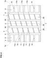
- FIG. 4 shows a development view of the tread portion 2 of the tire 1 according to another embodiment of the present invention.
- one first land region 7 is defined between two shoulder circumferential grooves 6.
- the first land region 7 in this embodiment includes three block rows 25 which will be described later.
- this first land region 7 is provided with a plurality of first axial grooves 11 each extending from one of the shoulder circumferential grooves 6 to the other shoulder circumferential groove 6, and the first axial grooves 11 are arranged in the above-mentioned first arrangement over the entire circumference of the tire. Even in this configuration, the noise performance can be improved while the steering stability is maintained through the mechanism described above.
- the first land region 7 in this embodiment is provided with one or more longitudinal grooves 20 that cross the multiple first axial grooves 11 in the tire circumferential direction.
- the longitudinal grooves 20 may extend continuously in the tire circumferential direction and may have substantially the same configuration as the crown circumferential grooves 5 shown in FIG. 1 .
- the longitudinal grooves 20 extend continuously in the tire circumferential direction over the entire circumference of the tire, thereby, the first land region 7 is divided into three block rows 25.
- the above-mentioned first axial grooves 11 and the longitudinal grooves 20 improve the noise performance while ensuring the wet performance.
- Pneumatic tires of size 195/65R15 having a tread portion as shown in FIG. 1 or FIG. 4 were made by way of test as tires in Examples 1 and 2.
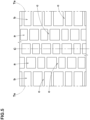
- Tires having the tread portion shown in FIG. 5 were made by way of test as tires in Reference.
- each of the first land regions (a) and the second land regions (b) of the tires in the Reference is provided with axial grooves (c) extending parallel to the tire axial direction and arranged so as to have the same pitch variation.
- the tires in the Reference are substantially the same as the tires in the Examples except for the above points.
- Noise was measured when each test tire was run on a drum testing machine under conditions of a vertical load of 4.51 kN and at a speed from 40 to 100 km/h.
- the results are expressed as an index with the reciprocal of the sound pressure of the noise in the Reference being 100, wherein the larger the numerical value, the smaller the noise is, which indicates superior noise performance.
- Table 1 Reference Example 1 Example 2 Figure showing Tread pattern FIG. 5 FIG. 1 FIG. 4 Noise performance [index] 100 130 115 Steering stability [evaluation point] 100 100 120
- the present invention includes the following aspects.
Landscapes
- Engineering & Computer Science (AREA)
- Mechanical Engineering (AREA)
- Tires In General (AREA)
Applications Claiming Priority (1)
| Application Number | Priority Date | Filing Date | Title |
|---|---|---|---|
| JP2023144506A JP2025037529A (ja) | 2023-09-06 | 2023-09-06 | タイヤ |
Publications (2)
| Publication Number | Publication Date |
|---|---|
| EP4520548A1 true EP4520548A1 (de) | 2025-03-12 |
| EP4520548B1 EP4520548B1 (de) | 2026-03-25 |
Family
ID=92295663
Family Applications (1)
| Application Number | Title | Priority Date | Filing Date |
|---|---|---|---|
| EP24193691.3A Active EP4520548B1 (de) | 2023-09-06 | 2024-08-08 | Reifen |
Country Status (4)
| Country | Link |
|---|---|
| US (1) | US20250074117A1 (de) |
| EP (1) | EP4520548B1 (de) |
| JP (1) | JP2025037529A (de) |
| CN (1) | CN119567763A (de) |
Citations (5)
| Publication number | Priority date | Publication date | Assignee | Title |
|---|---|---|---|---|
| EP0524568A1 (de) * | 1991-07-26 | 1993-01-27 | The Goodyear Tire & Rubber Company | Lauffläche mit mehreren Umfanglängenänderungen der Profilelemente |
| US5769990A (en) * | 1994-06-21 | 1998-06-23 | Michelin Recherche Et Technique S.A. | Method of making tire with tire tread pitch bands |
| US20150375571A1 (en) * | 2013-01-31 | 2015-12-31 | The Yokohama Rubber Co., Ltd. | Pneumatic Tire |
| US20180147891A1 (en) * | 2016-11-28 | 2018-05-31 | Toyo Tire & Rubber Co., Ltd. | Pneumatic tire |
| JP2022122121A (ja) | 2021-02-09 | 2022-08-22 | 住友ゴム工業株式会社 | タイヤ |
Family Cites Families (6)
| Publication number | Priority date | Publication date | Assignee | Title |
|---|---|---|---|---|
| JP2800943B2 (ja) * | 1989-10-02 | 1998-09-21 | 住友ゴム工業 株式会社 | 空気入りタイヤ |
| JP2971960B2 (ja) * | 1991-01-16 | 1999-11-08 | 住友ゴム工業株式会社 | 空気入りタイヤ |
| JP3924049B2 (ja) * | 1997-07-08 | 2007-06-06 | 株式会社ブリヂストン | オール・シーズン乗用車用空気入りラジアル・タイヤ |
| JP5149957B2 (ja) * | 2010-12-14 | 2013-02-20 | 住友ゴム工業株式会社 | 空気入りタイヤ |
| JP6082378B2 (ja) * | 2014-11-28 | 2017-02-15 | 住友ゴム工業株式会社 | 空気入りタイヤ |
| JP7733297B2 (ja) * | 2021-09-17 | 2025-09-03 | 横浜ゴム株式会社 | タイヤ |
-
2023
- 2023-09-06 JP JP2023144506A patent/JP2025037529A/ja active Pending
-
2024
- 2024-08-05 US US18/794,345 patent/US20250074117A1/en active Pending
- 2024-08-08 EP EP24193691.3A patent/EP4520548B1/de active Active
- 2024-08-21 CN CN202411149749.2A patent/CN119567763A/zh active Pending
Patent Citations (5)
| Publication number | Priority date | Publication date | Assignee | Title |
|---|---|---|---|---|
| EP0524568A1 (de) * | 1991-07-26 | 1993-01-27 | The Goodyear Tire & Rubber Company | Lauffläche mit mehreren Umfanglängenänderungen der Profilelemente |
| US5769990A (en) * | 1994-06-21 | 1998-06-23 | Michelin Recherche Et Technique S.A. | Method of making tire with tire tread pitch bands |
| US20150375571A1 (en) * | 2013-01-31 | 2015-12-31 | The Yokohama Rubber Co., Ltd. | Pneumatic Tire |
| US20180147891A1 (en) * | 2016-11-28 | 2018-05-31 | Toyo Tire & Rubber Co., Ltd. | Pneumatic tire |
| JP2022122121A (ja) | 2021-02-09 | 2022-08-22 | 住友ゴム工業株式会社 | タイヤ |
Also Published As
| Publication number | Publication date |
|---|---|
| EP4520548B1 (de) | 2026-03-25 |
| JP2025037529A (ja) | 2025-03-18 |
| US20250074117A1 (en) | 2025-03-06 |
| CN119567763A (zh) | 2025-03-07 |
Similar Documents
| Publication | Publication Date | Title |
|---|---|---|
| US11427033B2 (en) | Tire | |
| EP3178668B1 (de) | Luftreifen | |
| EP2151333B1 (de) | Luftreifen | |
| US9004125B2 (en) | Pneumatic tire | |
| US8302647B2 (en) | Pneumatic tire | |
| US11535062B2 (en) | Tyre | |
| US11571934B2 (en) | Tire | |
| US12594791B2 (en) | Tire | |
| US20220097456A1 (en) | Tire | |
| US11904639B2 (en) | Tire | |
| US11135878B2 (en) | Tire | |
| EP3988336B1 (de) | Reifen | |
| EP4039506B1 (de) | Reifen | |
| EP4520548A1 (de) | Reifen | |
| CN114537051B (zh) | 轮胎 | |
| US11780270B2 (en) | Tire | |
| US11772429B2 (en) | Tire | |
| US11820175B2 (en) | Tyre | |
| EP4431311A1 (de) | Reifen | |
| US11738603B2 (en) | Tire | |
| JP2025103289A (ja) | タイヤ |
Legal Events
| Date | Code | Title | Description |
|---|---|---|---|
| PUAI | Public reference made under article 153(3) epc to a published international application that has entered the european phase |
Free format text: ORIGINAL CODE: 0009012 |
|
| STAA | Information on the status of an ep patent application or granted ep patent |
Free format text: STATUS: THE APPLICATION HAS BEEN PUBLISHED |
|
| AK | Designated contracting states |
Kind code of ref document: A1 Designated state(s): AL AT BE BG CH CY CZ DE DK EE ES FI FR GB GR HR HU IE IS IT LI LT LU LV MC ME MK MT NL NO PL PT RO RS SE SI SK SM TR |
|
| P01 | Opt-out of the competence of the unified patent court (upc) registered |
Free format text: CASE NUMBER: APP_12461/2025 Effective date: 20250313 |
|
| STAA | Information on the status of an ep patent application or granted ep patent |
Free format text: STATUS: REQUEST FOR EXAMINATION WAS MADE |
|
| 17P | Request for examination filed |
Effective date: 20250715 |
|
| GRAP | Despatch of communication of intention to grant a patent |
Free format text: ORIGINAL CODE: EPIDOSNIGR1 |
|
| STAA | Information on the status of an ep patent application or granted ep patent |
Free format text: STATUS: GRANT OF PATENT IS INTENDED |
|
| RIC1 | Information provided on ipc code assigned before grant |
Ipc: B60C 11/03 20060101AFI20251201BHEP |
|
| INTG | Intention to grant announced |
Effective date: 20251215 |
|
| RAP3 | Party data changed (applicant data changed or rights of an application transferred) |
Owner name: SUMITOMO RUBBER INDUSTRIES, LTD. |
|
| GRAS | Grant fee paid |
Free format text: ORIGINAL CODE: EPIDOSNIGR3 |
|
| GRAA | (expected) grant |
Free format text: ORIGINAL CODE: 0009210 |
|
| STAA | Information on the status of an ep patent application or granted ep patent |
Free format text: STATUS: THE PATENT HAS BEEN GRANTED |
|
| AK | Designated contracting states |
Kind code of ref document: B1 Designated state(s): AL AT BE BG CH CY CZ DE DK EE ES FI FR GB GR HR HU IE IS IT LI LT LU LV MC ME MK MT NL NO PL PT RO RS SE SI SK SM TR |
|
| REG | Reference to a national code |
Ref country code: CH Ref legal event code: F10 Free format text: ST27 STATUS EVENT CODE: U-0-0-F10-F00 (AS PROVIDED BY THE NATIONAL OFFICE) Effective date: 20260325 Ref country code: GB Ref legal event code: FG4D |
|
| REG | Reference to a national code |
Ref country code: DE Ref legal event code: R096 Ref document number: 602024003416 Country of ref document: DE |
|
| REG | Reference to a national code |
Ref country code: IE Ref legal event code: FG4D |