EP4520557A1 - Wärmeverwaltungsmodul für ein fahrzeug - Google Patents
Wärmeverwaltungsmodul für ein fahrzeug Download PDFInfo
- Publication number
- EP4520557A1 EP4520557A1 EP23195650.9A EP23195650A EP4520557A1 EP 4520557 A1 EP4520557 A1 EP 4520557A1 EP 23195650 A EP23195650 A EP 23195650A EP 4520557 A1 EP4520557 A1 EP 4520557A1
- Authority
- EP
- European Patent Office
- Prior art keywords
- fluid
- management module
- thermal management
- housing portion
- cover plate
- Prior art date
- Legal status (The legal status is an assumption and is not a legal conclusion. Google has not performed a legal analysis and makes no representation as to the accuracy of the status listed.)
- Withdrawn
Links
Images





Classifications
-
- B—PERFORMING OPERATIONS; TRANSPORTING
- B60—VEHICLES IN GENERAL
- B60H—ARRANGEMENTS OF HEATING, COOLING, VENTILATING OR OTHER AIR-TREATING DEVICES SPECIALLY ADAPTED FOR PASSENGER OR GOODS SPACES OF VEHICLES
- B60H1/00—Heating, cooling or ventilating devices
- B60H1/00485—Valves for air-conditioning devices, e.g. thermostatic valves
-
- B—PERFORMING OPERATIONS; TRANSPORTING
- B60—VEHICLES IN GENERAL
- B60K—ARRANGEMENT OR MOUNTING OF PROPULSION UNITS OR OF TRANSMISSIONS IN VEHICLES; ARRANGEMENT OR MOUNTING OF PLURAL DIVERSE PRIME-MOVERS IN VEHICLES; AUXILIARY DRIVES FOR VEHICLES; INSTRUMENTATION OR DASHBOARDS FOR VEHICLES; ARRANGEMENTS IN CONNECTION WITH COOLING, AIR INTAKE, GAS EXHAUST OR FUEL SUPPLY OF PROPULSION UNITS IN VEHICLES
- B60K11/00—Arrangement in connection with cooling of propulsion units
- B60K11/02—Arrangement in connection with cooling of propulsion units with liquid cooling
Definitions
- the present invention relates to heat management systems in vehicles. More specifically, the present invention relates to an improved and efficient thermal management module for the vehicles, such as electric and/or hybrid vehicles.
- thermal management systems are used in vehicles to regulate heat flows inside the vehicles in order to ensure operation of the vehicle components in their respective optimal temperature range while ensuring the passenger comfort in the cabin.
- a thermal management module is used for management of heat from drive units, such as electric motors, the power electronics and the batteries and/or to keep these components at right temperature.
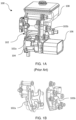
- a conventional thermal management module 100 such as one shown in FIG. 1A and FIG. 1B , includes a fluid hub 102, one or more heat exchangers, such as a chiller, 106, one or more fluid pumps 104, and a surge tank 108.
- the chiller 106, fluid pumps 104 and the surge tank 108 are configured on the fluid hub 102.
- a housing of the fluid hub 102 is generally formed by two plastic components 102a and 102b, wherein at least one of the two plastic housing components 102a and 102b is configured with channels that define the fluid flow passages when the two plastic housing components 102a and 102b are joined.
- the present invention discloses an improved and efficient thermal management module for vehicles, such as electric and/or hybrid vehicles.
- the disclosed thermal management module includes a fluid hub comprising a chamber to receive a valve mechanism, one or more fluid pumps configured in fluidic connection with the fluid hub, and at least one heat exchanger configured with the fluid hub.
- the fluid hub comprises a housing body having one or more fluid loops, and at least one cover plate adapted to cover at least one of the one or more fluid loops of the housing body.
- the housing body is made of a polymeric material.
- the cover plate is made of a metallic material, such as but not limited to aluminum.
- cover plate and the housing body can be coupled to each other together through fasteners.
- a portion of the cover plate can be coupled to a first side plate of the heat exchanger through any or a combination of brazing and welding.
- the cover plate can be integrated with a first side plate of the heat exchanger.
- the housing body is coupled to a second side plate of the heat exchanger through at least one mounting leg protruded from the housing body and at least one mounting bolt screwed through mounting holes of the mounting leg and a mounting block secured on the heat exchanger.
- the second side plate is positioned on a side opposite to that of the first side plate.
- the housing body comprises a first housing portion defining the chamber to accommodate the valve mechanism and fluidically connected to a surge tank through a first conduit, a second housing portion fluidically connected to the first housing portion through a second conduit, and a third housing portion fluidically connected to the first housing portion through a third conduit.
- the second housing portion and the third housing portion are configured to receive the one or more fluid pumps.
- the second housing portion and the third housing portion are configured on two opposite sides of the first housing portion.
- Each of the second housing portion and the third housing portion comprises at least one fluid connection terminal.
- the second housing portion can be fluidically connected to the heat exchanger through a tube.
- the cover plate can include a water box adapted to fluidically connect the second housing portion to the heat exchanger.
- the housing body comprises one or more first fluid connectors projected outside of the housing body.
- the cover plate comprises one or more second fluid connectors connected to the fluid loops of the housing body and projected outside from the cover plate.
- the thermal management module further comprises brackets secured to the heat exchanger to mount the thermal management module on a vehicle frame.
- Each of the brackets comprises a mounting hole with an anti-vibration grommet.
- a fluid hub/coolant hub of the thermal management module includes a housing body having one or more fluid loops, and a cover plate adapted to cover at least one of the one or more fluid loops of the housing body, which can obviate the drawbacks of the conventional fluid hub having two plastic housing components that are connected through the complex plastic welding process.
- the disclosed thermal management module eliminate the need of second housing main plastic component therefore eliminating the need of complex plastic welding process as well as specific tools and/or machines required for the complex plastic welding, resulting in reduction of manufacturing cost and the manufacturing time.
- the size/volume of the fluid hub is reduced which require less space for packaging and less coolant/fluid volume is required for same functionality of the conventional fluid hub.
- thermal management module for the vehicles
- concept of the present invention or the thermal management module of present invention is applicable for use in vehicular as well as non-vehicular environment, and all such applications are within scope of the present invention without any limitations whatsoever.
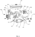
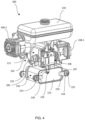
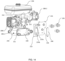
- a thermal management module 200 includes a fluid hub 202, one or more fluid pumps, such as pumps 208-1 and 208-2, configured in fluidic connection with the fluid hub 202, at least one heat exchanger, such as a chiller 210, configured with the fluid hub 202.
- the fluid hub 202 comprises a housing body 212 having one or more fluid loops 214, and a cover plate 216 adapted to cover at least one of the one or more fluid loops 214 of the housing body 212.
- the fluid loops 214 can be internal fluid passages defined in the housing body 212.
- the housing body 212 comprises a first housing portion 232 defining a chamber 204 to receive and accommodate a valve 205 of a valve mechanism 206.
- the valve mechanism 206 can be a multiway solenoid valve mechanism that can direct/regulate flow of the fluid/coolant received in the chamber 204 between several fluid loops and/or the heat exchanger 210.
- the valve 205 is controlled by a control unit/actuator 207 of the valve mechanism 206 and is adapted to selectively regulate fluid flow through the internal fluid flow passages/fluid loops 214.
- the valve actuator 207 is mounted on the housing body through a valve cover 209.
- the housing body 212 is made of a polymeric material.
- the housing body 212 can be made of one or more plastics, thermoplastic material, a duroplastic material, a compound material, such as a thermoplastic and duroplastic compound material, at least one polypropylene material and/or at least one polyamide material.
- the cover plate 216 is made of a metallic material, such as aluminum and/or aluminum alloys.
- a portion, for instance the wider and/or upper portion, of the cover plate 216 is coupled to the housing body 212 through fasteners 218 and seals.
- the cover plate 216 is provide with mounting holes 215.
- the fasteners 218 can be threaded bolts extended through the mounting holes 215 of the cover plate 216 and the corresponding holes 221 on the housing body 212.
- another portion, for instance a lower portion, of the cover plate 216 can be coupled to a first side plate 220 of the heat exchanger 210 through any or a combination of brazing and welding.
- the housing body 212 is coupled to a second side plate 222 of the heat exchanger 210 through a mounting leg 224 protruded from the housing body 212 and a mounting bolt 226 screwed through mounting holes of the mounting leg 224 and a mounting block 228 secured on the heat exchanger 210.
- the second side plate 222 is positioned on a side opposite to that of the first side plate 220.
- the fluid hub 202 is secured to the heat exchanger 210 from two opposite sides.
- the housing body 212 includes one or more first fluid connectors 233 projected outside of the housing body 212.
- the first fluid connectors 233 can be fluidically connected to at least one of the fluid loops 214 of the housing body 212.
- the housing body 212 is made through the injection molding process.
- the cover plate 216 comprises one or more second fluid connectors 235 fluidically connected to at least one of the fluid loops 214 of the housing body 212 and projected outside from the cover plate 216.
- the second fluid connectors 235 are fluidically connected to the fluid loops 214 though the openings 217 provided in the cover plate 216.
- the second fluid connectors 235 are also made of metallic material.
- the second fluid connectors 235 are made of same material of the cover plate 216.
- the second fluid connectors 235 also called quick connectors, can be quickly connected with a hose/pipe.
- the second fluid connectors 235 can be welded and/or brazed to the cover plate 216.
- the second fluid connectors 235 formed on the cover plate 216 reduce the plastic injection process limitations, for instance demolding process, for the housing body 212.
- the second fluid connectors 235 of metallic material facilitate higher flexibility for the second fluid connectors design.
- second fluid connectors 235 can have bend/irregular shape/design and can be secured to the cover plate 216 at any specific angle with the cover plate 216 based on requirement.
- brackets 250 are provided with the heat exchanger 210 to mount the thermal management module 200 on a vehicle frame.
- Each of the brackets 250 includes a mounting hole 252 and an anti-vibration grommet/rubber vibration damper 254.
- the heat exchanger 210 acts as a structural element of the housing body 212.
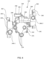
- the first housing portion 232 is fluidically connected to a surge tank 234 through a first conduit 236 that receive a fluid connector 231 protruded from the surge tank 234. More specifically, the first housing portion 232 receives fluid stored in the surge tank 234 and selectively supplies fluid to the heat exchanger 210 and/or other components of the vehicle based on the operative configuration of the valve 205 and/or valve mechanism 206 of the fluid hub 202.
- a first mounting arm 256 is protruded from the first housing portion 232 to detachably secure the surge tank 234 to the first housing portion 232.
- the first mounting arm 256 comprises an opening 258 to detachably engage with a locking hook 260 protruded from the surge tank 234.
- the locking hook 260 and the first mounting arm 256 can be in snap locking connection.
- a mounting plate 259 is protruded from the first housing portion 232, particularly from an outer surface of a fluid inlet passage 241. When the surge tank 234 is fitted on the housing body 212, the mounting plate 259 is received in the groove 223 provided on the surge tank 234.
- the fluid inlet passage 241 is configured in fluidic connection with the chamber 204 and the first conduit 236.
- the housing body 212 further includes a second housing portion 238 fluidically connected to the first housing portion 232 through a second conduit 240, and a third housing portion 242 fluidically connected to the first housing portion 232 through a third conduit 244.
- the second housing portion 238 and the third housing portion 242 are configured on two opposite sides of the first housing portion 232 along a first axis, called the transverse axis, of the housing body 212.
- the second housing portion 238 is configured to receive the fluid pump 208-1
- the third housing portion 242 is configured to receive the fluid pump 208-2.
- the pumps 208-1 and 208-2 can be radial pumps.
- one or more second mounting arms 262 are protruded from the second housing portion 238 to detachably secure the respective fluid pump 208-1 to the second housing portion 238.
- Each of the second mounting arms 262 comprises a mounting hole 263.
- Threaded bolts 261a are screwed through corresponding mounting holes 208a in the pump 208-1 and the mounting holes 263 in the second mounting arms 262 to secure the pump 208-1 to the second housing portion 238.
- one or more third mounting arms 264 are protruded from the third housing portion 242 to detachably secure the respective fluid pump 208-2 to the third housing portion 242.
- Each of the third mounting arms 264 comprises a mounting hole 265. Threaded bolts 261b are screwed through the mounting holes 208b in the pump 208-2 and the mounting holes 265 of the third mounting arms 264 to secure the pump 208-2 to the third housing portion 242.
- the housing body 212 further includes fluid connection terminals 246-1 and 246-2, external to the housing body 212, on the second housing portion 238 and the third housing portion 242.
- the second housing portion 238 is fluidically connected to the fluid connection terminal 246-1
- the third housing portion 242 is fluidically connected to the fluid connection terminal 246-2.
- the fluid connection terminals 246-1 and 246-2 can be used for the inlet or outlet of the pumps 208-1 and 208-2.
- the second housing portion 238 can be fluidically connected to the heat exchanger 210 through a tube 248, as shown in FIG. 2 .
- the tube 248 can be connected between the fluid connection terminal 246-1 and a fluid connection terminal of the heat exchanger 210.
- the cover plate 216 can be a stepped plate having a bent portion 219.
- the bent portion/stepped portion 219 allows the cover plate 216 to properly abuts, at its both opposite end portions, to the housing body 212 and the heat exchanger 210 when the side portion of the housing body 212 is extended beyond the first side plate 220.
- the cover plate 216 can be integrated with the first side plate 220 of the heat exchanger 210.
- the cover plate 216 and the first side plate 220 are a single element.
- the heat exchanger 210 is not used only as a structural element of the fluid hub housing for using natural heat exchanger stiffness but also as the cover of the housing body 212 for covering the fluid loops 214.
- the cover plate 216 can include a water box 249 on an extended portion 213 of the cover plate 216.
- the extended portion 213 includes spaced openings 225a and 225b corresponding to the fluid connection terminals 246-1 and the fluid connection opening 211 of the heat exchanger 210.
- the water box 249 is adapted to fluidically connect the second housing portion 238 to the heat exchanger 210 through the openings 225a and 225b.
- the water box 249 can be welded and/or brazed to the cover plate 216.
Landscapes
- Engineering & Computer Science (AREA)
- Mechanical Engineering (AREA)
- Chemical & Material Sciences (AREA)
- Combustion & Propulsion (AREA)
- Transportation (AREA)
- Physics & Mathematics (AREA)
- Thermal Sciences (AREA)
- Valve Housings (AREA)
Priority Applications (1)
| Application Number | Priority Date | Filing Date | Title |
|---|---|---|---|
| EP23195650.9A EP4520557A1 (de) | 2023-09-06 | 2023-09-06 | Wärmeverwaltungsmodul für ein fahrzeug |
Applications Claiming Priority (1)
| Application Number | Priority Date | Filing Date | Title |
|---|---|---|---|
| EP23195650.9A EP4520557A1 (de) | 2023-09-06 | 2023-09-06 | Wärmeverwaltungsmodul für ein fahrzeug |
Publications (1)
| Publication Number | Publication Date |
|---|---|
| EP4520557A1 true EP4520557A1 (de) | 2025-03-12 |
Family
ID=87933742
Family Applications (1)
| Application Number | Title | Priority Date | Filing Date |
|---|---|---|---|
| EP23195650.9A Withdrawn EP4520557A1 (de) | 2023-09-06 | 2023-09-06 | Wärmeverwaltungsmodul für ein fahrzeug |
Country Status (1)
| Country | Link |
|---|---|
| EP (1) | EP4520557A1 (de) |
Citations (6)
| Publication number | Priority date | Publication date | Assignee | Title |
|---|---|---|---|---|
| CN110614895A (zh) * | 2018-06-20 | 2019-12-27 | 浙江三花汽车零部件有限公司 | 热管理系统及热管理组件 |
| CN111038216A (zh) * | 2019-12-30 | 2020-04-21 | 华域三电汽车空调有限公司 | 一种阀体集成模块及热泵空调系统 |
| CN112428773A (zh) * | 2020-11-06 | 2021-03-02 | 三花控股集团有限公司 | 流体控制组件及热管理系统 |
| CN113246688A (zh) * | 2021-06-16 | 2021-08-13 | 广州小鹏汽车科技有限公司 | 热管理系统、控制方法和车辆 |
| KR20220125936A (ko) * | 2021-03-08 | 2022-09-15 | 주식회사 두원공조 | 차량용 열관리 모듈 |
| CN115139750A (zh) * | 2022-09-05 | 2022-10-04 | 浙江凌昇动力科技有限公司 | 热管理集成模块及电动汽车 |
-
2023
- 2023-09-06 EP EP23195650.9A patent/EP4520557A1/de not_active Withdrawn
Patent Citations (6)
| Publication number | Priority date | Publication date | Assignee | Title |
|---|---|---|---|---|
| CN110614895A (zh) * | 2018-06-20 | 2019-12-27 | 浙江三花汽车零部件有限公司 | 热管理系统及热管理组件 |
| CN111038216A (zh) * | 2019-12-30 | 2020-04-21 | 华域三电汽车空调有限公司 | 一种阀体集成模块及热泵空调系统 |
| CN112428773A (zh) * | 2020-11-06 | 2021-03-02 | 三花控股集团有限公司 | 流体控制组件及热管理系统 |
| KR20220125936A (ko) * | 2021-03-08 | 2022-09-15 | 주식회사 두원공조 | 차량용 열관리 모듈 |
| CN113246688A (zh) * | 2021-06-16 | 2021-08-13 | 广州小鹏汽车科技有限公司 | 热管理系统、控制方法和车辆 |
| CN115139750A (zh) * | 2022-09-05 | 2022-10-04 | 浙江凌昇动力科技有限公司 | 热管理集成模块及电动汽车 |
Similar Documents
| Publication | Publication Date | Title |
|---|---|---|
| KR102721560B1 (ko) | 냉각수 가열 히터 모듈 | |
| US8286615B2 (en) | Intake manifold of an internal combustion engine and cooling fluid charge air cooler | |
| CN212979863U (zh) | 车辆用冷却水综合热管理装置 | |
| US12139005B2 (en) | Component node and a component carrier for the component node | |
| EP3936709B1 (de) | Bauteilgehäuseeinheit und fahrzeugwärmemanagementsystem mit einer bauteilgehäuseeinheit | |
| US20190322155A1 (en) | Heater module for heating cooling water | |
| US11614024B2 (en) | Reservoir tank assembly for vehicle | |
| US5931228A (en) | Cooling module having a mounting plate with integral attachment sites and channels | |
| KR102439104B1 (ko) | 일체형 차량용 냉각수 히팅 모듈 | |
| JP5192540B2 (ja) | 作業車両 | |
| US20250020229A1 (en) | Cooling module | |
| US20240317017A1 (en) | Thermal management system | |
| EP4520557A1 (de) | Wärmeverwaltungsmodul für ein fahrzeug | |
| US9666913B2 (en) | Heat transfer device | |
| JP4622473B2 (ja) | クーリングモジュール | |
| EP1614904B1 (de) | Hydrauliksystem mit Tank und Pumpenansaugvorrichtung für ein Kraftfahrzeug | |
| EP4523932A1 (de) | Wärmeverwaltungsmodul für ein fahrzeug | |
| US20220196348A1 (en) | Support and connection device | |
| KR102780707B1 (ko) | 차량 엔진룸의 배열체 | |
| US20250132631A1 (en) | Drive apparatus | |
| JP2006008118A (ja) | 自動車の車室の空調機において、熱交換器の気密を保ちかつ振動を防止するカバー付きハウジング | |
| CN119812556A (zh) | 用于电池模块的冷却系统歧管 | |
| EP3543550B1 (de) | Wärmetauscher | |
| EP4653701A1 (de) | Kühlmittelnabe mit integriertem pumpengehäuse | |
| EP4653700A1 (de) | Kühlmittelnabe mit integrierter achse |
Legal Events
| Date | Code | Title | Description |
|---|---|---|---|
| PUAI | Public reference made under article 153(3) epc to a published international application that has entered the european phase |
Free format text: ORIGINAL CODE: 0009012 |
|
| STAA | Information on the status of an ep patent application or granted ep patent |
Free format text: STATUS: THE APPLICATION HAS BEEN PUBLISHED |
|
| AK | Designated contracting states |
Kind code of ref document: A1 Designated state(s): AL AT BE BG CH CY CZ DE DK EE ES FI FR GB GR HR HU IE IS IT LI LT LU LV MC ME MK MT NL NO PL PT RO RS SE SI SK SM TR |
|
| STAA | Information on the status of an ep patent application or granted ep patent |
Free format text: STATUS: THE APPLICATION IS DEEMED TO BE WITHDRAWN |
|
| 18D | Application deemed to be withdrawn |
Effective date: 20250913 |