EP4520573A1 - Véhicule ferroviaire comprenant une batterie de traction et un convertisseur de courant ainsi que procédé de mise en marche d'un véhicule ferroviaire - Google Patents
Véhicule ferroviaire comprenant une batterie de traction et un convertisseur de courant ainsi que procédé de mise en marche d'un véhicule ferroviaire Download PDFInfo
- Publication number
- EP4520573A1 EP4520573A1 EP23196460.2A EP23196460A EP4520573A1 EP 4520573 A1 EP4520573 A1 EP 4520573A1 EP 23196460 A EP23196460 A EP 23196460A EP 4520573 A1 EP4520573 A1 EP 4520573A1
- Authority
- EP
- European Patent Office
- Prior art keywords
- converter
- rail vehicle
- traction battery
- power converter
- vehicle
- Prior art date
- Legal status (The legal status is an assumption and is not a legal conclusion. Google has not performed a legal analysis and makes no representation as to the accuracy of the status listed.)
- Granted
Links
Images

Classifications
-
- B—PERFORMING OPERATIONS; TRANSPORTING
- B60—VEHICLES IN GENERAL
- B60L—PROPULSION OF ELECTRICALLY-PROPELLED VEHICLES; SUPPLYING ELECTRIC POWER FOR AUXILIARY EQUIPMENT OF ELECTRICALLY-PROPELLED VEHICLES; ELECTRODYNAMIC BRAKE SYSTEMS FOR VEHICLES IN GENERAL; MAGNETIC SUSPENSION OR LEVITATION FOR VEHICLES; MONITORING OPERATING VARIABLES OF ELECTRICALLY-PROPELLED VEHICLES; ELECTRIC SAFETY DEVICES FOR ELECTRICALLY-PROPELLED VEHICLES
- B60L1/00—Supplying electric power to auxiliary equipment of vehicles
-
- B—PERFORMING OPERATIONS; TRANSPORTING
- B60—VEHICLES IN GENERAL
- B60L—PROPULSION OF ELECTRICALLY-PROPELLED VEHICLES; SUPPLYING ELECTRIC POWER FOR AUXILIARY EQUIPMENT OF ELECTRICALLY-PROPELLED VEHICLES; ELECTRODYNAMIC BRAKE SYSTEMS FOR VEHICLES IN GENERAL; MAGNETIC SUSPENSION OR LEVITATION FOR VEHICLES; MONITORING OPERATING VARIABLES OF ELECTRICALLY-PROPELLED VEHICLES; ELECTRIC SAFETY DEVICES FOR ELECTRICALLY-PROPELLED VEHICLES
- B60L50/00—Electric propulsion with power supplied within the vehicle
- B60L50/40—Electric propulsion with power supplied within the vehicle using propulsion power supplied by capacitors
-
- B—PERFORMING OPERATIONS; TRANSPORTING
- B60—VEHICLES IN GENERAL
- B60L—PROPULSION OF ELECTRICALLY-PROPELLED VEHICLES; SUPPLYING ELECTRIC POWER FOR AUXILIARY EQUIPMENT OF ELECTRICALLY-PROPELLED VEHICLES; ELECTRODYNAMIC BRAKE SYSTEMS FOR VEHICLES IN GENERAL; MAGNETIC SUSPENSION OR LEVITATION FOR VEHICLES; MONITORING OPERATING VARIABLES OF ELECTRICALLY-PROPELLED VEHICLES; ELECTRIC SAFETY DEVICES FOR ELECTRICALLY-PROPELLED VEHICLES
- B60L58/00—Methods or circuit arrangements for monitoring or controlling batteries or fuel cells, specially adapted for electric vehicles
- B60L58/10—Methods or circuit arrangements for monitoring or controlling batteries or fuel cells, specially adapted for electric vehicles for monitoring or controlling batteries
-
- B—PERFORMING OPERATIONS; TRANSPORTING
- B61—RAILWAYS
- B61C—LOCOMOTIVES; MOTOR RAILCARS
- B61C3/00—Electric locomotives or railcars
- B61C3/02—Electric locomotives or railcars with electric accumulators
-
- H—ELECTRICITY
- H02—GENERATION; CONVERSION OR DISTRIBUTION OF ELECTRIC POWER
- H02J—ELECTRIC POWER NETWORKS; CIRCUIT ARRANGEMENTS OR SYSTEMS FOR SUPPLYING OR DISTRIBUTING ELECTRIC POWER; SYSTEMS FOR STORING ELECTRIC ENERGY
- H02J7/00—Circuit arrangements for charging or discharging batteries or for supplying loads from batteries
- H02J7/14—Circuit arrangements for charging or discharging batteries or for supplying loads from batteries for charging batteries from dynamo-electric generators driven at varying speed, e.g. on vehicle
-
- H—ELECTRICITY
- H02—GENERATION; CONVERSION OR DISTRIBUTION OF ELECTRIC POWER
- H02J—ELECTRIC POWER NETWORKS; CIRCUIT ARRANGEMENTS OR SYSTEMS FOR SUPPLYING OR DISTRIBUTING ELECTRIC POWER; SYSTEMS FOR STORING ELECTRIC ENERGY
- H02J7/00—Circuit arrangements for charging or discharging batteries or for supplying loads from batteries
- H02J7/34—Parallel operation in networks using both storage and other DC sources, e.g. providing buffering
- H02J7/345—Parallel operation in networks using both storage and other DC sources, e.g. providing buffering using capacitors as storage or buffering devices
-
- B—PERFORMING OPERATIONS; TRANSPORTING
- B60—VEHICLES IN GENERAL
- B60L—PROPULSION OF ELECTRICALLY-PROPELLED VEHICLES; SUPPLYING ELECTRIC POWER FOR AUXILIARY EQUIPMENT OF ELECTRICALLY-PROPELLED VEHICLES; ELECTRODYNAMIC BRAKE SYSTEMS FOR VEHICLES IN GENERAL; MAGNETIC SUSPENSION OR LEVITATION FOR VEHICLES; MONITORING OPERATING VARIABLES OF ELECTRICALLY-PROPELLED VEHICLES; ELECTRIC SAFETY DEVICES FOR ELECTRICALLY-PROPELLED VEHICLES
- B60L2200/00—Type of vehicles
- B60L2200/26—Rail vehicles
-
- B—PERFORMING OPERATIONS; TRANSPORTING
- B60—VEHICLES IN GENERAL
- B60L—PROPULSION OF ELECTRICALLY-PROPELLED VEHICLES; SUPPLYING ELECTRIC POWER FOR AUXILIARY EQUIPMENT OF ELECTRICALLY-PROPELLED VEHICLES; ELECTRODYNAMIC BRAKE SYSTEMS FOR VEHICLES IN GENERAL; MAGNETIC SUSPENSION OR LEVITATION FOR VEHICLES; MONITORING OPERATING VARIABLES OF ELECTRICALLY-PROPELLED VEHICLES; ELECTRIC SAFETY DEVICES FOR ELECTRICALLY-PROPELLED VEHICLES
- B60L2210/00—Converter types
- B60L2210/10—DC to DC converters
- B60L2210/12—Buck converters
-
- B—PERFORMING OPERATIONS; TRANSPORTING
- B60—VEHICLES IN GENERAL
- B60L—PROPULSION OF ELECTRICALLY-PROPELLED VEHICLES; SUPPLYING ELECTRIC POWER FOR AUXILIARY EQUIPMENT OF ELECTRICALLY-PROPELLED VEHICLES; ELECTRODYNAMIC BRAKE SYSTEMS FOR VEHICLES IN GENERAL; MAGNETIC SUSPENSION OR LEVITATION FOR VEHICLES; MONITORING OPERATING VARIABLES OF ELECTRICALLY-PROPELLED VEHICLES; ELECTRIC SAFETY DEVICES FOR ELECTRICALLY-PROPELLED VEHICLES
- B60L2210/00—Converter types
- B60L2210/30—AC to DC converters
-
- B—PERFORMING OPERATIONS; TRANSPORTING
- B60—VEHICLES IN GENERAL
- B60L—PROPULSION OF ELECTRICALLY-PROPELLED VEHICLES; SUPPLYING ELECTRIC POWER FOR AUXILIARY EQUIPMENT OF ELECTRICALLY-PROPELLED VEHICLES; ELECTRODYNAMIC BRAKE SYSTEMS FOR VEHICLES IN GENERAL; MAGNETIC SUSPENSION OR LEVITATION FOR VEHICLES; MONITORING OPERATING VARIABLES OF ELECTRICALLY-PROPELLED VEHICLES; ELECTRIC SAFETY DEVICES FOR ELECTRICALLY-PROPELLED VEHICLES
- B60L2210/00—Converter types
- B60L2210/40—DC to AC converters
-
- B—PERFORMING OPERATIONS; TRANSPORTING
- B60—VEHICLES IN GENERAL
- B60L—PROPULSION OF ELECTRICALLY-PROPELLED VEHICLES; SUPPLYING ELECTRIC POWER FOR AUXILIARY EQUIPMENT OF ELECTRICALLY-PROPELLED VEHICLES; ELECTRODYNAMIC BRAKE SYSTEMS FOR VEHICLES IN GENERAL; MAGNETIC SUSPENSION OR LEVITATION FOR VEHICLES; MONITORING OPERATING VARIABLES OF ELECTRICALLY-PROPELLED VEHICLES; ELECTRIC SAFETY DEVICES FOR ELECTRICALLY-PROPELLED VEHICLES
- B60L2240/00—Control parameters of input or output; Target parameters
- B60L2240/40—Drive Train control parameters
- B60L2240/54—Drive Train control parameters related to batteries
- B60L2240/547—Voltage
-
- H—ELECTRICITY
- H02—GENERATION; CONVERSION OR DISTRIBUTION OF ELECTRIC POWER
- H02J—ELECTRIC POWER NETWORKS; CIRCUIT ARRANGEMENTS OR SYSTEMS FOR SUPPLYING OR DISTRIBUTING ELECTRIC POWER; SYSTEMS FOR STORING ELECTRIC ENERGY
- H02J2105/00—Networks for supplying or distributing electric power characterised by their spatial reach or by the load
- H02J2105/30—Networks for supplying or distributing electric power characterised by their spatial reach or by the load the load networks being external to vehicles, i.e. exchanging power with vehicles
- H02J2105/33—Networks for supplying or distributing electric power characterised by their spatial reach or by the load the load networks being external to vehicles, i.e. exchanging power with vehicles exchanging power with road vehicles
- H02J2105/37—Networks for supplying or distributing electric power characterised by their spatial reach or by the load the load networks being external to vehicles, i.e. exchanging power with vehicles exchanging power with road vehicles exchanging power with electric vehicles [EV] or with hybrid electric vehicles [HEV]
Definitions
- the invention relates to a rail vehicle comprising a traction battery and a power converter and a method for switching on a rail vehicle.
- Powered rail vehicles with a traction system and an extra-low voltage level are known from the state of the art.
- the extra-low voltage level serves to supply the vehicle control system and other low-power consumers.
- these consumers are powered by a combination of an extra-low voltage battery and a charger. Adequate space must be provided in the vehicle for such a charger.
- the installation of a separate extra-low voltage battery is also complex.
- Extra-low voltage batteries in rail vehicles contain lead and/or nickel-cadmium.
- the object is achieved by a rail vehicle with a traction battery and a power converter and by a method for switching on a rail vehicle according to the independent claims.
- a rail vehicle comprising a traction battery and a power converter.
- the power converter can be supplied with electrical power by the traction battery.
- the power converter is connected to a DC on-board electrical system via a converter-voltage converter.
- a vehicle voltage converter is arranged between the traction battery and the DC on-board electrical system.
- the vehicle voltage converter can be designed as a low-power DC/DC voltage converter.
- Such a vehicle voltage converter makes it possible to supply the vehicle control system and the vehicle system with voltage from the traction battery, even when the power converter is not yet in operation.
- This arrangement makes it possible to power up the rail vehicle system using energy from the traction battery. This eliminates the need for a separate battery for the rail vehicle system and the vehicle control system, allowing the rail vehicle to be designed in a simple and lightweight manner.
- the traction battery is electrically connected to the on-board DC power supply.
- a traction battery voltage converter is formed between the traction battery and the power converter.
- Such an arrangement allows the DC on-board power supply to be supplied from the traction battery. This eliminates the need for an additional battery for the DC on-board power supply, allowing the rail vehicle to be designed simply, with minimal weight and space.
- the DC electrical system has a voltage in the range of 24 to 110 V.
- Such a voltage allows the rail vehicle system and the vehicle control technology to be operated safely and reliably.
- the converter voltage transformer is integrated in the converter.
- This arrangement of the power converter and the converter-voltage converter allows for a compact and space-saving arrangement of the components within the rail vehicle. This leaves sufficient room for passengers or other technical equipment.
- the converter voltage transformer and the converter can be arranged in a common housing and/or in a common compartment of the rail vehicle.
- Such an auxiliary converter makes it possible to supply auxiliary equipment with the voltage required for its operation. This allows the auxiliary equipment to be operated safely and efficiently.
- the auxiliary converter can be integrated into the power converter.
- the auxiliary converter is located in the same housing or at least close to the power converter.
- both the converter voltage converter and the auxiliary converter to be integrated into the power converter.
- the power converter, the converter voltage converter, and the auxiliary converter are arranged in one housing or at least in a corresponding compartment of a rail vehicle. In this way, the components are arranged compactly in one housing or in a technical compartment, and there is sufficient space in the rail vehicle for passengers or for other technical equipment.
- the auxiliary converter can provide three-phase alternating current for low-power consumers.
- the three-phase alternating current can have a voltage of 400 V and a frequency of 50 Hertz.
- the auxiliary converter can be powered by an external power source.
- the external power source can supply the auxiliary converter with a voltage of 400 V and a frequency of 50 Hertz. This allows the rail vehicle, for example, to be supplied with electrical power in a workshop, allowing the auxiliary systems to operate.
- the rail vehicle prefferably includes supercapacitors designed to buffer energy within the rail vehicle.
- the energy can be buffered by the supercapacitors for emergency loads and/or for switching operations.
- multiple supercapacitors to be configured as energy buffers in the rail vehicle.
- the loads that are electrically connected to the SuperCaps can therefore be operated continuously and without any risk of interference, even during switching operations.
- the object of the invention is further achieved by a method for switching on a rail vehicle as described above.
- the vehicle voltage converter When the rail vehicle is switched on, the vehicle voltage converter first supplies the DC electrical system with energy from the traction battery before the power converter is activated.
- Such a process makes it possible to supply the DC electrical system with electrical current without the need for a voltage source other than the traction battery.
- the power converter is activated via the power converter voltage converter from the DC on-board network.
- the power converter is supplied with energy directly from the traction battery.
- Direct means that the power converter is supplied with energy from the traction battery, without any essential electrical components other than electrical cables between the power converter and the traction battery. This ensures a simple and direct power supply to the power converter from the traction battery.
- the DC electrical system is supplied with energy via the power converter and the traction battery.
- a traction battery voltage converter can be arranged between the traction battery and the vehicle voltage converter.
- the traction battery voltage converter can be electrically connected to the vehicle voltage converter, the traction battery, and the battery management system. It is possible for the vehicle voltage converter to be powered up using electrical energy from the traction battery via the traction battery voltage converter.
- the traction battery voltage converter can be operated with a power of 250W.
- the vehicle voltage converter can be operated with a power of 2kW.
- the vehicle voltage converter can be operated with a power that is 4 to 12 times the power at which the traction battery voltage converter can be operated. It is possible for the vehicle voltage converter to be operated with a power that is 6 to 10 times the power at which the traction battery voltage converter can be operated.
- the vehicle voltage converter can supply the DC electrical system with electrical power within a short time without the need for a complex start-up. If the converter fails, the DC electrical system can be supplied without interruption. from the vehicle voltage converter in hot standby mode. This enables safe operation of the rail vehicle.
- the battery management system is started up using energy provided by the traction battery.
- the battery management system can be powered up with energy provided by the traction battery via the traction battery voltage converter.
- the vehicle voltage converter is supplied with a voltage of 24 - 110V via the traction battery voltage converter during the starting process.
- the network between the traction battery voltage converter and the vehicle voltage converter as well as the network between the traction battery voltage converter and the power converter preferably has a voltage of 700-950V during normal operation after the system has started up.
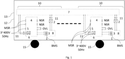
- the Figure 1 shows a rail vehicle 12 with a rail vehicle carriage 13.
- the rail vehicle carriage 13 has several wheels 15.
- the rail vehicle carriage 13 has two traction systems 10.
- the two traction systems 10 are connected to the DC on-board network 7.
- the DC on-board network 7 has a voltage between 24 and 110 V.
- the traction systems 10 are identical.
- the traction systems 10 have a converter-voltage converter 6 and a vehicle voltage converter 2. Both the converter-voltage converter 6 and the vehicle voltage converter 2 are equipped with a 24 V to 110 V DC output.
- the vehicle voltage converter 2 and the converter-voltage converter 6 are each connected to the DC on-board network 7 via the 24 V to 110 V DC output 11.
- the vehicle voltage converter 2 is electrically connected to the traction battery 8.
- the traction battery 8 is equipped with a battery management system 1.
- the power converter 4 is electrically connected directly to the traction battery 8.
- the power converter 4 has an auxiliary converter 5.
- the auxiliary converter 5 provides three-phase alternating current for low-power consumers (not shown).
- the three-phase alternating current of the auxiliary converter 5 has a voltage of 400 V and a frequency of 50 Hertz.
- the rail vehicle 12 consists of a rail vehicle carriage 13. It is possible for only one traction system 10 to be formed in a rail vehicle carriage 13, or for multiple traction systems 10 to be formed.
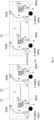
- the Figure 2 shows a rail vehicle 12 with two rail vehicle carriages 13.
- the rail vehicle carriages 13 are each a rail vehicle carriage 13 analogous to the rail vehicle carriage 13 from the Figure 1 .
- the rail vehicle 12 consists of two rail vehicle carriages 13.
- the rail vehicle 12 consists of a plurality of rail vehicle carriages 13.
- each rail vehicle carriage 13 has at least one traction system 10.
- non-powered rail vehicle carriages are formed in the rail vehicle 12.
- the non-powered rail vehicle carriages do not comprise a traction system 10.
- the powered rail vehicle carriages 13 of the rail vehicle 12 are formed as end carriages and that non-powered intermediate carriages are located between the rail vehicle carriages 13 formed as end carriages. It is also possible that the powered rail vehicle carriages 13 of the rail vehicle 12 are formed as intermediate carriages and that the two end carriages of the rail vehicle 12 are not powered. It is possible that the traction battery 8 and the vehicle voltage converter 2 and the DC on-board network 7 of a traction system 10, a power converter 4 of another traction system 10 on the rail vehicle 13 is powered up. The power converter 4 is then powered up via the power converter 4 of the other traction system 10 via the DC on-board network 7. It is also possible for a power converter 4 of another traction system 10 on another rail vehicle 13 to be powered up via the traction battery 8 and the vehicle voltage converter 2 and the DC on-board network 7 of a traction system 10 on a rail vehicle 13.
- steps B - E are started and/or carried out by a battery management system 1.
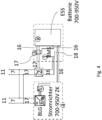
- the Figure 4 shows a detailed illustration of a power converter 4 and a traction battery 8.
- the traction battery 8 is electrically connected to the power converter 4 via a 700V - 950V network 16.
- Two switches 18 are arranged in the 700V - 950V network 16 between the traction battery 8 and the power converter 4.
- the traction battery 8 is connected to the battery management system 1 via a 700V - 950V network 16.
- the traction battery 8 is electrically connected to the traction battery voltage converter 3 via a 700V - 950V network 16.
- the traction battery voltage converter 3 is electrically connected to the battery management system 1 and to the vehicle voltage converter 2 via a 24V - 110V network 17.
- the traction battery voltage converter 3 thus converts the voltage from the 700V - 950V network 16 to the voltage in the 24V - 110V network 17.
- the battery management system 1 is connected to the vehicle voltage converter 2 via the 700V - 950V network 16.
- the vehicle voltage converter 2 supplies electrical energy to the DC on-board network 7 via the 24V - 110V network 17 via the DC output 11.
- the vehicle voltage converter 2 is connected to the converter voltage converter 6 of the converter 4 via the 24V - 110V network 17.
- the converter voltage converter 6 is electrically connected to the auxiliary converter 5.
- the start-up of the rail vehicle 12 proceeds as follows:
- the vehicle voltage converter 2 is started by the traction battery voltage converter 3 with energy from the traction battery 8. Once the vehicle voltage converter 2 has been started, it is supplied with a 700V - 950V voltage 16 via the battery management system 1.
- the vehicle voltage converter 2 then supplies the 24V - 110V network 17 between the vehicle voltage converter 2 and the power converter 4 with electrical energy.
- the power converter 4 is started via the power converter voltage converter 6 with electrical energy from the 24V - 110V network 17 from the vehicle voltage converter 2.
- the power converter voltage converter 6 supplies the auxiliary converter 5 with electrical current.
- the power converter 4 is supplied with electrical energy directly from the traction battery 8 via the 700V - 950V network 16.
- the switches 18 are closed when the power converter 2 has been started.
Landscapes
- Engineering & Computer Science (AREA)
- Power Engineering (AREA)
- Transportation (AREA)
- Mechanical Engineering (AREA)
- Life Sciences & Earth Sciences (AREA)
- Sustainable Development (AREA)
- Sustainable Energy (AREA)
- Electric Propulsion And Braking For Vehicles (AREA)
Priority Applications (1)
| Application Number | Priority Date | Filing Date | Title |
|---|---|---|---|
| EP23196460.2A EP4520573B1 (fr) | 2023-09-11 | 2023-09-11 | Véhicule ferroviaire comprenant une batterie de traction et un convertisseur de courant ainsi que procédé de mise en marche d'un véhicule ferroviaire |
Applications Claiming Priority (1)
| Application Number | Priority Date | Filing Date | Title |
|---|---|---|---|
| EP23196460.2A EP4520573B1 (fr) | 2023-09-11 | 2023-09-11 | Véhicule ferroviaire comprenant une batterie de traction et un convertisseur de courant ainsi que procédé de mise en marche d'un véhicule ferroviaire |
Publications (2)
| Publication Number | Publication Date |
|---|---|
| EP4520573A1 true EP4520573A1 (fr) | 2025-03-12 |
| EP4520573B1 EP4520573B1 (fr) | 2026-03-18 |
Family
ID=88017597
Family Applications (1)
| Application Number | Title | Priority Date | Filing Date |
|---|---|---|---|
| EP23196460.2A Active EP4520573B1 (fr) | 2023-09-11 | 2023-09-11 | Véhicule ferroviaire comprenant une batterie de traction et un convertisseur de courant ainsi que procédé de mise en marche d'un véhicule ferroviaire |
Country Status (1)
| Country | Link |
|---|---|
| EP (1) | EP4520573B1 (fr) |
Citations (6)
| Publication number | Priority date | Publication date | Assignee | Title |
|---|---|---|---|---|
| DE102014219641A1 (de) * | 2014-09-29 | 2016-03-31 | Siemens Aktiengesellschaft | Bordnetz für ein Schienenfahrzeug |
| DE102014224922A1 (de) * | 2014-12-04 | 2016-06-09 | Bombardier Transportation Gmbh | Schienenfahrzeug mit elektrischem Bordnetz, Bordnetzbatterie und Batterieladegerät, sowie Verfahren zum Betreiben des Schienenfahrzeugs |
| US20160185224A1 (en) * | 2014-12-31 | 2016-06-30 | General Electric Company | System and method for controlling electrically driven accessories |
| US9731616B2 (en) * | 2012-03-28 | 2017-08-15 | Mitsubishi Electric Corporation | Railway vehicle system |
| EP3705336A1 (fr) * | 2017-11-03 | 2020-09-09 | CRRC Zhuzhou Locomotive Co., Ltd | Circuit de puissance hybride de trafic ferroviaire, bloc batterie de stockage d'énergie et procédé d'alimentation électrique associé |
| DE102021201828A1 (de) * | 2021-02-26 | 2022-09-01 | Siemens Mobility GmbH | Energieversorgungsanordnung und Verfahren, insbesondere für die Energieversorgung elektrisch betriebener Fahrzeuge, beispielsweise Schienenfahrzeuge sowie elektrisch betriebenes Fahrzeug, insbesondere Schienenfahrzeug |
-
2023
- 2023-09-11 EP EP23196460.2A patent/EP4520573B1/fr active Active
Patent Citations (6)
| Publication number | Priority date | Publication date | Assignee | Title |
|---|---|---|---|---|
| US9731616B2 (en) * | 2012-03-28 | 2017-08-15 | Mitsubishi Electric Corporation | Railway vehicle system |
| DE102014219641A1 (de) * | 2014-09-29 | 2016-03-31 | Siemens Aktiengesellschaft | Bordnetz für ein Schienenfahrzeug |
| DE102014224922A1 (de) * | 2014-12-04 | 2016-06-09 | Bombardier Transportation Gmbh | Schienenfahrzeug mit elektrischem Bordnetz, Bordnetzbatterie und Batterieladegerät, sowie Verfahren zum Betreiben des Schienenfahrzeugs |
| US20160185224A1 (en) * | 2014-12-31 | 2016-06-30 | General Electric Company | System and method for controlling electrically driven accessories |
| EP3705336A1 (fr) * | 2017-11-03 | 2020-09-09 | CRRC Zhuzhou Locomotive Co., Ltd | Circuit de puissance hybride de trafic ferroviaire, bloc batterie de stockage d'énergie et procédé d'alimentation électrique associé |
| DE102021201828A1 (de) * | 2021-02-26 | 2022-09-01 | Siemens Mobility GmbH | Energieversorgungsanordnung und Verfahren, insbesondere für die Energieversorgung elektrisch betriebener Fahrzeuge, beispielsweise Schienenfahrzeuge sowie elektrisch betriebenes Fahrzeug, insbesondere Schienenfahrzeug |
Also Published As
| Publication number | Publication date |
|---|---|
| EP4520573B1 (fr) | 2026-03-18 |
Similar Documents
| Publication | Publication Date | Title |
|---|---|---|
| DE102011011800B4 (de) | Verfahren zur Spannungsversorgung für ein Fahrzeug sowie entsprechende Vorrichtung und Fahrzeug | |
| EP3500473B1 (fr) | Système d'alimentation en énergie d'un véhicule sur rail | |
| EP3634803B1 (fr) | Source de puissance pour un vehicule ferroviare | |
| DE102012223901B4 (de) | Stromversorgungseinrichtung für ein Schienenfahrzeug | |
| EP3625098A1 (fr) | Véhicule ferroviaire prévu pour effectuer une opération sur une voie ferrée | |
| DE102021116525A1 (de) | Vorrichtung und Verfahren zur elektrischen Versorgung eines Niederspannungs-Bordnetzes eines Kraftfahrzeugs, insbesondere Elektrokraftfahrzeugs | |
| DE102017116107B3 (de) | Topologie für ein Fahrzeug, Verfahren zum Laden eines Fahrzeugs | |
| DE102017210750A1 (de) | Bordnetz für ein Schienenfahrzeug, Verfahren zum Betreiben des Bordnetzes und Schienenfahrzeug | |
| DE202017104921U1 (de) | Antriebsvorrichtung für ein Funktionsfahrzeug | |
| DE102020007869A1 (de) | Elektrisches Bordnetzsystem für ein elektrisch angetriebenes Fahrzeug und dazugehöriges Verfahren | |
| EP3969321A1 (fr) | Chargeur de bord et procédé pour charger une batterie haute tension d'un réseau de bord haute tension ou une batterie basse tension d'un réseau de bord basse tension | |
| DE102017209451A1 (de) | Elektrisches Energieversorgungssystem, Verfahren und Computerprogramm zum Betreiben des Energieversorgungssystems und Computerprogrammprodukt | |
| WO2022194433A1 (fr) | Appareil et procédé permettant de fournir de l'électricité à un système d'alimentation électrique embarqué basse tension d'un véhicule à moteur, en particulier d'un véhicule à moteur électrique | |
| WO2023036495A1 (fr) | Procédé et dispositif permettant de faire fonctionner un véhicule à propulsion électrique | |
| EP4520573B1 (fr) | Véhicule ferroviaire comprenant une batterie de traction et un convertisseur de courant ainsi que procédé de mise en marche d'un véhicule ferroviaire | |
| EP3818210B1 (fr) | Véhicule ferroviaire | |
| DE102018207014A1 (de) | Verfahren zum Betreiben eines Hochvoltbordnetzes eines Kraftfahrzeugs, und Hochvoltbordnetz | |
| DE102016226148A1 (de) | Elektrische Vorrichtung für ein Schienenfahrzeug | |
| DE102020113562A1 (de) | Schienenfahrzeug mit einem automatischen Erdungsschalter und Verfahren zum Erden von elektrischen Leitern in einem Bereich eines Schienenfahrzeugs | |
| EP4146496B1 (fr) | Charge des accumulateurs d'énergie d'un véhicule sur un réseau d'alimentation énergétique faible | |
| WO2023161025A1 (fr) | Procédé de fonctionnement d'un véhicule à chariot à batterie hybride et véhicule à chariot à batterie hybride | |
| DE102024209534B3 (de) | Antriebssystem für ein Schienenfahrzeug | |
| EP3798042B1 (fr) | Véhicule ferroviaire alimenté par batteries | |
| DE102011104223A1 (de) | Verfahren zur Deaktivierung eines Hochspannungsnetzes mit einer zugeordneten Hochspannungsbatterie eines Kraftfahrzeugs und Kraftfahrzeug | |
| DE102016104541B4 (de) | Ladesystem für Elektro- und Hybridfahrzeuge und ein Verfahren zum Laden mit einem Lade-system |
Legal Events
| Date | Code | Title | Description |
|---|---|---|---|
| PUAI | Public reference made under article 153(3) epc to a published international application that has entered the european phase |
Free format text: ORIGINAL CODE: 0009012 |
|
| STAA | Information on the status of an ep patent application or granted ep patent |
Free format text: STATUS: THE APPLICATION HAS BEEN PUBLISHED |
|
| AK | Designated contracting states |
Kind code of ref document: A1 Designated state(s): AL AT BE BG CH CY CZ DE DK EE ES FI FR GB GR HR HU IE IS IT LI LT LU LV MC ME MK MT NL NO PL PT RO RS SE SI SK SM TR |
|
| STAA | Information on the status of an ep patent application or granted ep patent |
Free format text: STATUS: REQUEST FOR EXAMINATION WAS MADE |
|
| 17P | Request for examination filed |
Effective date: 20250721 |
|
| STAA | Information on the status of an ep patent application or granted ep patent |
Free format text: STATUS: EXAMINATION IS IN PROGRESS |
|
| 17Q | First examination report despatched |
Effective date: 20250910 |
|
| GRAP | Despatch of communication of intention to grant a patent |
Free format text: ORIGINAL CODE: EPIDOSNIGR1 |
|
| STAA | Information on the status of an ep patent application or granted ep patent |
Free format text: STATUS: GRANT OF PATENT IS INTENDED |
|
| INTG | Intention to grant announced |
Effective date: 20251112 |
|
| GRAS | Grant fee paid |
Free format text: ORIGINAL CODE: EPIDOSNIGR3 |
|
| GRAA | (expected) grant |
Free format text: ORIGINAL CODE: 0009210 |
|
| STAA | Information on the status of an ep patent application or granted ep patent |
Free format text: STATUS: THE PATENT HAS BEEN GRANTED |
|
| AK | Designated contracting states |
Kind code of ref document: B1 Designated state(s): AL AT BE BG CH CY CZ DE DK EE ES FI FR GB GR HR HU IE IS IT LI LT LU LV MC ME MK MT NL NO PL PT RO RS SE SI SK SM TR |
|
| REG | Reference to a national code |
Ref country code: CH Ref legal event code: F10 Free format text: ST27 STATUS EVENT CODE: U-0-0-F10-F00 (AS PROVIDED BY THE NATIONAL OFFICE) Effective date: 20260318 Ref country code: GB Ref legal event code: FG4D Free format text: NOT ENGLISH |
|
| REG | Reference to a national code |
Ref country code: DE Ref legal event code: R096 Ref document number: 502023003407 Country of ref document: DE |
|
| REG | Reference to a national code |
Ref country code: IE Ref legal event code: FG4D Free format text: LANGUAGE OF EP DOCUMENT: GERMAN |