EP4520596A1 - Coffre de transport, en particulier coffre de toit, pour véhicule automobile - Google Patents
Coffre de transport, en particulier coffre de toit, pour véhicule automobile Download PDFInfo
- Publication number
- EP4520596A1 EP4520596A1 EP24204615.9A EP24204615A EP4520596A1 EP 4520596 A1 EP4520596 A1 EP 4520596A1 EP 24204615 A EP24204615 A EP 24204615A EP 4520596 A1 EP4520596 A1 EP 4520596A1
- Authority
- EP
- European Patent Office
- Prior art keywords
- closure
- shell
- transport box
- base shell
- hinge
- Prior art date
- Legal status (The legal status is an assumption and is not a legal conclusion. Google has not performed a legal analysis and makes no representation as to the accuracy of the status listed.)
- Pending
Links
Images




Classifications
-
- B—PERFORMING OPERATIONS; TRANSPORTING
- B60—VEHICLES IN GENERAL
- B60R—VEHICLES, VEHICLE FITTINGS, OR VEHICLE PARTS, NOT OTHERWISE PROVIDED FOR
- B60R9/00—Supplementary fittings on vehicle exterior for carrying loads, e.g. luggage, sports gear or the like
- B60R9/04—Carriers associated with vehicle roof
- B60R9/055—Enclosure-type carriers, e.g. containers, boxes
Definitions
- Such a transport box is from the WO 2017/001651 A1 known.
- the known transport box has a base shell and a lid shell, which can be joined together and, when joined together, define a transport volume.
- the lid shell is held to the base shell by means of a total of six hinge locks, with three hinge locks being provided on each of the longitudinal sides of the transport box.
- the hinge locks can be adjusted between two different positions. In a first position, they lock the lid shell relative to the base shell. In this position, the hinge locks on each of the longitudinal sides define a common pivot hinge to fold the lid shell open relative to the base shell. In a second position, the hinge locks on each of the longitudinal sides completely release the lid shell to allow the lid shell to be opened.
- the control of the hinge locks for moving into the different positions is carried out by a manually operated actuating device which has two actuating elements arranged on the opposite longitudinal sides.
- the respective actuating element is coupled to the three hinge closures on each of the longitudinal sides by means of a tension and compression-resistant movement transmission band, which is mounted longitudinally displaceably on a longitudinal side wall of the base shell.
- the object of the invention is to create a transport box of the type mentioned above which enables the safe retention of goods in the transport box even in the event of crash-related loads.
- a securing device with at least one securing element is additionally provided in a front and/or rear area of the transport box, by means of which - in the closed position of the lid shell - the lid shell is locked against the base shell at the front and/or rear.
- the securing device ensures additional protection in the area of at least one front side of the transport box, since in addition to the longitudinal hinge closures, an additional positive-locking lock is also provided at least at the front or rear or even at the front and rear, which prevents one front side of the lid shell from becoming detached from the corresponding front side of the base shell.
- the lid shell and the base shell could deform in such a way that the transport box gaped open at the front and transported goods could thus be thrown out of the transport box onto a roadway.
- three or more hinged closures are provided on opposite longitudinal sides.
- the solution according to the invention is particularly advantageously suited for transport boxes that are preferably attached to the roof of passenger cars or mobile homes.
- a transport box according to the invention can also be attached to the side of a corresponding motor vehicle in the same way.
- the transport box according to the invention is attached in the longitudinal direction of the respective motor vehicle, so that opposite longitudinal sides of the transport box are also accessible from one of the vehicle's longitudinal sides when the transport box is mounted.
- the securing device has at least one closure arrangement on the front and/or rear side, which closure arrangement has at least two closure parts that can be brought into operative connection with one another, one of which is assigned to the cover shell and the other to the base shell.
- the closure arrangement has at least two closure parts, one of which is fastened to the cover shell and the other to the base shell.
- at least one third closure part is provided, which is movably mounted relative to the two stationary closure parts in order to connect the two closure parts to one another in a form-fitting manner or to connect the two closure parts for a To release the opening movement relative to each other.
- the at least one movable closure part is also referred to as the closure control part.
- the closure parts are arranged to be movable relative to one another between a locking position that locks the lid shell and the base shell together and an open position that releases the lid shell and the base shell relative to one another.
- the closure parts have a closure control part that is arranged to be movable relative to the base shell and can be coupled to a closure part attached to the lid shell on the one hand and a closure part attached to the base shell on the other hand in such a way that the closure parts are locked relative to one another or released relative to one another.
- the manually operable actuating device is designed by means of at least one flexible, tensile and compressively rigid motion transmission line for controlling at least one movable closure part forming a closure control part for transfer into the locked position or the open position.
- the motion transmission line is preferably coupled to a movably arranged closure control part of the closure arrangement.
- a metal strip mounted for linear movement in the base shell is preferably provided as the motion transmission line.
- the motion transmission line can also be made from a flat strip made of a different material. Alternatively, it is possible to form the motion transmission line from a cable with a round cross-section that is guided in a correspondingly adapted longitudinal guide in the base shell or the cover shell.
- the motion transmission line is advantageously guided in the area of the base shell, since the base shell is mounted securely to the vehicle when used on a motor vehicle roof, while the cover shell can be opened relative to the base shell. In principle, however, it is also possible to provide the motion transmission line in the area of the cover shell.
- a threaded cable with a pitch of 10 mm can also be used as the motion transmission line. This cable is provided with screw threads on its outer circumference and is displaced in a linear manner by means of a rotatable screw sleeve.
- the motion transmission line serves to control the movable closure control part of the respective closure arrangement.
- a single, circumferential, tension- and compression-resistant motion transmission line can be assigned to the transport box.
- at least two motion transmission lines can be provided, distributed over the circumference of the base shell, each extending into the area of the at least one frontal closure arrangement.
- the at least one other closure part is arranged in a stationary manner, and the closure parts have mutually complementary, positively interacting closure profiles.
- the movable closure part is the closure control part, and this closure control part interacts with two stationary closure parts, one of which is attached to the lid shell and the other to the base shell.
- the closure control part and the two stationary closure parts have mutually complementary, positively interacting closure profiles.
- the closure profiles are understood to include pin- or web-shaped profiles as well as groove- or recess-shaped profiles.
- the motion transmission line is coupled both to the at least one end-side closure arrangement and to the at least one longitudinal hinge closure such that the closure arrangement is unlocked in the release and hinge functions of the hinge closure and locked in the locking position of the hinge closure.
- a single, circumferential motion transmission line is provided, which is coupled to the at least one closure assembly and to all hinge closures.
- the circumferential motion transmission line is guided along a circumferential side wall of the base shell on an inner side of the base shell in linear guide sections that are integrally formed on the side wall of the base shell or are firmly connected to the inner side of the base shell.
- two movement lines are provided, each of which is longitudinally opposite the other and is coupled to the at least one end-side locking arrangement.
- This embodiment is advantageously combined with a manually operable actuating element in the region of the opposite long sides of the transport box. By operating the actuating element in the region of a long side, the movement line associated with this long side is thus displaced in order to unlock or lock the at least one end-side locking arrangement and to simultaneously lock or unlock the hinge locks of the corresponding long side.
- compensating or freewheel elements are coupled to the motion transmission line in the area of the at least one closure arrangement, which ensure alternative actuation of the closure arrangement by an actuating device on one long side or the other long side.
- Corresponding compensating or freewheel elements are mechanical components that are coupled to the motion transmission line and the closure arrangement in such a way that the actuation of the hinged closures on one long side necessarily also causes a complementary actuation of the front-side closure arrangement. This ensures that from a closed state of the transport box, when the hinged closures on one long side are unlocked by the actuating device, all closure assemblies on the front sides of the transport box are also opened, in order to enable the lid shell to subsequently pivot open relative to the base shell.
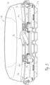
- a transport box in the form of a roof box 1 according to the Fig. 1 to 19 is designed to be mounted on the roof of a passenger car.
- the roof box 1 is equipped with a base shell 2 which, when mounted on the passenger car, is firmly connected to the roof area of the passenger car.
- the roof box 1 has, as Fig. 1 can be seen, has an elongated shape with two opposite longitudinal sides and two end faces defining a front end and a rear end of the roof box 1.
- the roof box 1 When mounted firmly on the vehicle, the roof box 1 is aligned in the longitudinal direction of the vehicle, so that the long sides of the roof box extend at least largely in the longitudinal direction of the vehicle.
- a front face of the roof box 1 facing forward in the direction of travel forms a front side.
- a front face facing rearward in the direction of travel forms a rear side or rear side of the roof box 1.
- the roof box also has a lid shell 3, which in the closed state ( Fig. 2 and 3 ) rests on a circumferential edge of the base shell 2 and, together with the base shell, defines a transport volume on the inside.
- the lid shell 3 is connected to the base shell 2 via a total of six hinge locks, with three hinge locks 4, 5 positioned at equal intervals on opposite long sides of the roof box 1.
- a central hinge lock 5 on each long side also has a manually operable actuating device, as described in more detail below. All hinge locks 4, 5 are designed identically with regard to their functions listed below.
- the hinge locks 4, 5 have a locking position in which the lid shell 3 is locked to the base shell 2 in the closed state.
- the hinge locks 4, 5 have a hinge function, with the three hinge locks on each long side defining a common hinge axis in order to be able to pivot the lid shell 3 open and closed relative to the base shell 2.
- the hinge locks 4, 5 have a release function in order to be able to open one long side of the roof box 1 at a time.
- the hinged closures 4, 5 of the long side to be opened are moved into a release position.
- the hinged closures 4, 5 each have a movably mounted closure control part, which interacts with a closure part fixed to the base shell and a closure part fixed to the lid shell in such a way that the two closure parts are released relative to each other, or that a positive pivot hinge is achieved, which simultaneously defines the locking function in this hinge position.
- each of the locking assemblies 6 is adjustable between a release position releasing the lid shell 3 relative to the base shell 2 and a locking position locking the corresponding front side of the lid shell 3 relative to the front side of the base shell.
- the roof box 1 also has a control joint 8 on the opposite end sides of the roof box 1, which is fastened on the inside to the base shell 2 and the lid shell 3 and additionally guides an opening and closing movement of the lid shell 3 relative to the base shell 2 and limits the maximum opening range of the lid shell 3.
- the longitudinal hinge closures 4, 5 and the front-end closure assemblies 6 are jointly controlled in a manner described in more detail below in order to realize the desired opening and locking or hinge functions of the roof box 1.
- the control is mechanical.
- These actuators can be controlled wirelessly or by wire via a control unit that can be integrated into the roof box or provided separately from the roof box.
- the hinge closures 4, 5 have Fig. 4 and 5 and 11 to 13 each have a lid-shell-fixed closure part 10 and a base-shell-fixed closure part 12, which can be coupled to one another or released relative to one another via a closure control part 11, 11' mounted for limited linear movement along the circumferential edge of the base shell 2.
- Each lid-shell-side Closure part 10 has a hinge pin extending parallel to the circumferential edge of the base shell 2, and the associated closure control part 11, 11' is provided with a complementary pin receptacle and a sliding profile. In the hinge position, the pin receptacle coaxially encloses the hinge pin of the closure part 10, thereby forming the hinge axis.
- each closure control part 11 has a large recess 18, a narrower intermediate guide 19 and a hinge recess 20.
- the hinge pin of the closure part 10 is located in the area of the large recess 18, the lid shell-side closure part 10 is released relative to the base shell-side closure part 12.
- the closure part 10 first reaches the intermediate guide 19, until the closure part 10 according to Fig. 13 is then positioned in the region of the hinge recess 20, in which the hinge pin of the closure part 10 is positioned in the hinge position of the closure control part 11, 11', which at the same time also defines the locking position of the respective hinge closure 4.
- 11' at least one movement transmission element 7 is provided, wherein according to the embodiment according to Fig. 2 a single, circumferential motion transmission element 7 is provided, which extends not only over the two longitudinal sides, but also over both end faces of the roof box 1 and is coupled to the two end-side locking arrangements 6 in the front and rear areas.
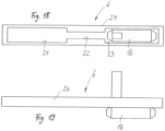
- the end-side locking arrangements 6 are also each provided with a locking part attached to the lid shell side and a locking part attached to the base shell side, each of which has a locking control part 24 ( Fig. 14 to 19 ) can be released or locked relative to each other.
- a locking control part 24 Fig. 14 to 19
- the closure control part 24 is designed such that a displacement in two opposite directions defines a release position, whereas a central positioning represents a locking function.
- the closure control part 24 has a central, narrow locking guide 22 and two release recesses 21 and 23 adjoining the central locking guide 22 on opposite sides.
- a locking pin 16, which is assigned to the lid-shell-side closure part, is thus positively engaged in the central locking guide 22, resulting in the desired locking function.
- Each closure arrangement 6 is designed identically, so that each closure arrangement 6 has a corresponding closure control part 24, which, analogous to the closure parts of the hinge closures 4, 5, interacts with a closure pin 16 of a lid-shell-side closure part and with a closure part attached to the base shell.
- the closure control parts 24 of the closure arrangements 6 are also connected to the rotating motion transmission element 7, which is designed as a tensile- and compression-resistant flat band and is laid on the inside along the circumferential edge of the base shell 2 for linear movement.
- the opposing hinge closures 4, 5 each have a freewheel in one direction of movement of the motion transmission element, so that the hinge closures of each of the longitudinal sides can only be moved from a closed position to the released position in one direction of movement.
- the movement transmission element 7 is displaced by an actuating device 9, which is arranged in Fig. 4
- the actuating device 9 is assigned to the middle hinge closure 5.
- a limited pivoting operating lever is provided which causes the movement of the movement transmission element 7.
- the described freewheel function serves to move the front-side locking arrangements 6 into their release position when the hinged closures 4, 5 on one long side are unlocked, while simultaneously leaving the hinged closures 4, 5 on the opposite long side in their locked position.
- the locking arrangements 6 can each be moved into a release position in both directions of movement of the motion transmission element 7. This means that from both opposite long sides, the respective actuating device 9 enables the lid shell 3 to be opened on one long side at a time, without the front-side locking arrangements 6 hindering such opening.
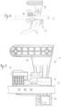
- two separate movement transmission strands 7a to 7c can be provided over the circumference of the base shell 2, which are connected to one another according to Fig. 6 either overlap in the area of the frontal closure arrangements 6 or according to Fig. 7 in the area of the frontal closure arrangements 6 are in operative connection with the closure arrangements 6 via an intermediate strand 7d.
- a first variant is based on the Fig. 8
- the closure assembly 6, 6a is attached to an unspecified joint component, which is connected at its opposite ends to a respective motion transmission line 7a, 7c or 7b, 7d.
- the joint component is dimensionally stable.
- Adjustment of the The corresponding closure control part of the closure arrangement 6, 6a is controlled by one of the two motion transmission strands 7a, 7c or 7b, 7d being positioned stationary, while the other motion transmission strand 7a, 7c or 7b, 7d is moved in the direction of the arrow.
- a front-end articulation point of the articulation component is stationary, and the articulation component performs a pivoting movement around this stationary articulation point.
- the stroke executed by the closure control part is less than the stroke of the respective motion transmission line. If this does not adequately transfer the closure control part from the locked position to the released position, it is possible to additionally provide a length compensation.
- a spring (not designated in more detail) is used to move the closure control part of the closure arrangement 6, 6a into a corresponding end position.
- the two motion transmission strands 7a, 7c and 7b, 7d each have a slot (not designated in more detail), the length of which corresponds to the stroke, i.e. the displacement, of the respective motion transmission strand 7a, 7c and 7b, 7d. If one motion transmission strand 7a, 7c is moved, the closure control part of the closure arrangement 6, 6a is moved into the other end position. The return is effected by the spring.
- the respective slot defines a freewheel for each motion transmission strand 7a, c; 7b, 7d.
- a guide track 13 is provided, in which a locking component is guided in a linearly movable manner.
- the locking component is connected to the respective movement transmission line 7, 7c, 7d by means of a coupling element 15.
- the respective locking component engages in a respective locking receptacle 14 of the closure control part of the closure arrangement 6, 6a, wherein the positive guidance of the respective locking component is designed such that the closure control part can only be carried by one of the two movement transmission lines, while the respective other locking component is not engaged with the other locking receptacle 14. This makes it possible to displace the closure control part by moving one movement transmission line 7, 7c, 7d at a time, without the opposite movement transmission line hindering this movement.
Landscapes
- Engineering & Computer Science (AREA)
- Mechanical Engineering (AREA)
- Fittings On The Vehicle Exterior For Carrying Loads, And Devices For Holding Or Mounting Articles (AREA)
Applications Claiming Priority (3)
| Application Number | Priority Date | Filing Date | Title |
|---|---|---|---|
| DE102021204105 | 2021-04-26 | ||
| DE102021209412.0A DE102021209412A1 (de) | 2020-10-06 | 2021-08-26 | Transportbox, insbesondere Dachbox, für ein Kraftfahrzeug |
| EP22168968.0A EP4082838B1 (fr) | 2021-04-26 | 2022-04-20 | Coffre de transport, en particulier coffre de toit, pour véhicule automobile |
Related Parent Applications (1)
| Application Number | Title | Priority Date | Filing Date |
|---|---|---|---|
| EP22168968.0A Division EP4082838B1 (fr) | 2021-04-26 | 2022-04-20 | Coffre de transport, en particulier coffre de toit, pour véhicule automobile |
Publications (1)
| Publication Number | Publication Date |
|---|---|
| EP4520596A1 true EP4520596A1 (fr) | 2025-03-12 |
Family
ID=81344515
Family Applications (3)
| Application Number | Title | Priority Date | Filing Date |
|---|---|---|---|
| EP22168968.0A Active EP4082838B1 (fr) | 2021-04-26 | 2022-04-20 | Coffre de transport, en particulier coffre de toit, pour véhicule automobile |
| EP24204615.9A Pending EP4520596A1 (fr) | 2021-04-26 | 2022-04-20 | Coffre de transport, en particulier coffre de toit, pour véhicule automobile |
| EP24167177.5A Active EP4371826B1 (fr) | 2021-04-26 | 2022-04-20 | Coffre de transport, en particulier coffre de toit, pour véhicule automobile |
Family Applications Before (1)
| Application Number | Title | Priority Date | Filing Date |
|---|---|---|---|
| EP22168968.0A Active EP4082838B1 (fr) | 2021-04-26 | 2022-04-20 | Coffre de transport, en particulier coffre de toit, pour véhicule automobile |
Family Applications After (1)
| Application Number | Title | Priority Date | Filing Date |
|---|---|---|---|
| EP24167177.5A Active EP4371826B1 (fr) | 2021-04-26 | 2022-04-20 | Coffre de transport, en particulier coffre de toit, pour véhicule automobile |
Country Status (3)
| Country | Link |
|---|---|
| EP (3) | EP4082838B1 (fr) |
| ES (1) | ES3010533T3 (fr) |
| PL (2) | PL4371826T3 (fr) |
Citations (4)
| Publication number | Priority date | Publication date | Assignee | Title |
|---|---|---|---|---|
| CA1116141A (fr) * | 1980-11-03 | 1982-01-12 | James A. Brown | Etui de transport et de rangement de skis et de leurs accessoires, ainsi que d'autres articles qu'il pourrait contenir |
| WO2017001651A1 (fr) | 2015-07-02 | 2017-01-05 | Thule Sweden Ab | Porte-charge comprenant un agencement de verrouillage |
| EP3587188A1 (fr) * | 2018-06-27 | 2020-01-01 | VDL Hapro B.V. | Coffre de toit avec système de verrouillage |
| WO2021023907A1 (fr) * | 2019-08-02 | 2021-02-11 | Luis Jose Diaz Salas | Coffre porte-bagages pliant amliéoré |
-
2022
- 2022-04-20 PL PL24167177.5T patent/PL4371826T3/pl unknown
- 2022-04-20 EP EP22168968.0A patent/EP4082838B1/fr active Active
- 2022-04-20 PL PL22168968.0T patent/PL4082838T3/pl unknown
- 2022-04-20 EP EP24204615.9A patent/EP4520596A1/fr active Pending
- 2022-04-20 ES ES22168968T patent/ES3010533T3/es active Active
- 2022-04-20 EP EP24167177.5A patent/EP4371826B1/fr active Active
Patent Citations (4)
| Publication number | Priority date | Publication date | Assignee | Title |
|---|---|---|---|---|
| CA1116141A (fr) * | 1980-11-03 | 1982-01-12 | James A. Brown | Etui de transport et de rangement de skis et de leurs accessoires, ainsi que d'autres articles qu'il pourrait contenir |
| WO2017001651A1 (fr) | 2015-07-02 | 2017-01-05 | Thule Sweden Ab | Porte-charge comprenant un agencement de verrouillage |
| EP3587188A1 (fr) * | 2018-06-27 | 2020-01-01 | VDL Hapro B.V. | Coffre de toit avec système de verrouillage |
| WO2021023907A1 (fr) * | 2019-08-02 | 2021-02-11 | Luis Jose Diaz Salas | Coffre porte-bagages pliant amliéoré |
Also Published As
| Publication number | Publication date |
|---|---|
| ES3010533T3 (en) | 2025-04-03 |
| EP4371826A2 (fr) | 2024-05-22 |
| EP4082838B1 (fr) | 2024-10-30 |
| EP4082838A1 (fr) | 2022-11-02 |
| PL4082838T3 (pl) | 2025-03-31 |
| EP4371826A3 (fr) | 2024-07-10 |
| EP4082838C0 (fr) | 2024-10-30 |
| EP4371826C0 (fr) | 2025-10-08 |
| PL4371826T3 (pl) | 2026-02-23 |
| EP4371826B1 (fr) | 2025-10-08 |
Similar Documents
| Publication | Publication Date | Title |
|---|---|---|
| EP2257443B1 (fr) | Portière coulissante pour un véhicule | |
| EP2859165B1 (fr) | Dispositif d'accouplement destiné à la liaison détachable d'une partie de carrosserie montée de manière à pivoter, telle que les portes d'un véhicule, le hayon ou le capot de ce dernier, à une partie structurelle d'une carrosserie du véhicule | |
| DE10218307B4 (de) | Dachkonstruktion für ein Cabriolet | |
| DE102020209607B4 (de) | Verschlussanordnung zum Verschließen einer Tankmulde einer Karosserie eines Kraftfahrzeugs | |
| EP2362041B1 (fr) | Verrouillage de protection contre les mines pour l'agencement sur des portes de véhicules militaires | |
| DE102020107054A1 (de) | Luftklappenvorrichtung mit Kniegelenkkopplung | |
| DE202015006895U1 (de) | Aufstellbares Klappenscharnier | |
| DE102009058583B4 (de) | Schiebetüre für ein Fahrzeug | |
| DE102008047046B4 (de) | Türantrieb für eine Schwenkschiebetür eines Fahrzeugs | |
| EP4371826B1 (fr) | Coffre de transport, en particulier coffre de toit, pour véhicule automobile | |
| DE102021209412A1 (de) | Transportbox, insbesondere Dachbox, für ein Kraftfahrzeug | |
| EP2025853B1 (fr) | Dispositif d'entraîneur pour un dispositif d'entraînement de porte, un tel dispositif d'entraînement de porte et une porte | |
| EP2357103B1 (fr) | Verrouillage pour un couvercle pour un véhicule de type cabriolet | |
| EP1529908A2 (fr) | Dispositif de fermeture pour capotes, hayons ou similaires d'un véhicule | |
| EP3744929B1 (fr) | Fermeture à crémone | |
| EP3517715B1 (fr) | Gâchette à déverrouillage auxiliaire | |
| DE10331144B4 (de) | Fahrzeugdach mit einem bewegbar gelagerten und verriegelbaren Dachbauteil | |
| DE10209811B4 (de) | Cabriolet-Fahrzeug mit Verdeckklappe und mit dieser koppelbarem Überrollbügel | |
| DE102021208515B4 (de) | Beschattungsvorrichtung für einen transparenten Flächenabschnitt eines Kraftfahrzeugs | |
| DE102004054160B4 (de) | Verdeck für ein Cabriolet-Fahrzeug | |
| DE102024120212B4 (de) | Schließvorrichtung für eine Öffnung eines Kraftfahrzeugs | |
| EP3744932B1 (fr) | Fermeture à crémone à déverrouillage de secours | |
| DE102019124646B4 (de) | Verriegelungseinrichtung | |
| DE102024124684A1 (de) | Verschlussvorrichtung für eine Öffnung in einer Außenkontur eines Kraftfahrzeugs | |
| DE102007044185A1 (de) | Türantrieb für eine Schwenkschiebetür eines Fahrzeugs |
Legal Events
| Date | Code | Title | Description |
|---|---|---|---|
| PUAI | Public reference made under article 153(3) epc to a published international application that has entered the european phase |
Free format text: ORIGINAL CODE: 0009012 |
|
| STAA | Information on the status of an ep patent application or granted ep patent |
Free format text: STATUS: THE APPLICATION HAS BEEN PUBLISHED |
|
| AC | Divisional application: reference to earlier application |
Ref document number: 4082838 Country of ref document: EP Kind code of ref document: P |
|
| AK | Designated contracting states |
Kind code of ref document: A1 Designated state(s): AL AT BE BG CH CY CZ DE DK EE ES FI FR GB GR HR HU IE IS IT LI LT LU LV MC MK MT NL NO PL PT RO RS SE SI SK SM TR |
|
| STAA | Information on the status of an ep patent application or granted ep patent |
Free format text: STATUS: REQUEST FOR EXAMINATION WAS MADE |
|
| 17P | Request for examination filed |
Effective date: 20250903 |