EP4520617A1 - Bewegungs- und verriegelungssystem für einen wagendeckel - Google Patents
Bewegungs- und verriegelungssystem für einen wagendeckel Download PDFInfo
- Publication number
- EP4520617A1 EP4520617A1 EP23196113.7A EP23196113A EP4520617A1 EP 4520617 A1 EP4520617 A1 EP 4520617A1 EP 23196113 A EP23196113 A EP 23196113A EP 4520617 A1 EP4520617 A1 EP 4520617A1
- Authority
- EP
- European Patent Office
- Prior art keywords
- cover
- wagon
- locking
- motor
- interaction element
- Prior art date
- Legal status (The legal status is an assumption and is not a legal conclusion. Google has not performed a legal analysis and makes no representation as to the accuracy of the status listed.)
- Pending
Links
Images


Classifications
-
- B—PERFORMING OPERATIONS; TRANSPORTING
- B61—RAILWAYS
- B61D—BODY DETAILS OR KINDS OF RAILWAY VEHICLES
- B61D39/00—Wagon or like covers; Tarpaulins; Movable or foldable roofs
- B61D39/002—Sliding or folding roofs
-
- B—PERFORMING OPERATIONS; TRANSPORTING
- B61—RAILWAYS
- B61D—BODY DETAILS OR KINDS OF RAILWAY VEHICLES
- B61D19/00—Door arrangements specially adapted for rail vehicles
- B61D19/001—Door arrangements specially adapted for rail vehicles for wagons or vans
-
- B—PERFORMING OPERATIONS; TRANSPORTING
- B61—RAILWAYS
- B61D—BODY DETAILS OR KINDS OF RAILWAY VEHICLES
- B61D39/00—Wagon or like covers; Tarpaulins; Movable or foldable roofs
- B61D39/006—Opening and closing means
Definitions
- the present description refers to a movement system for wagon cover, a locking system for wagon cover and a wagon comprising the movement and/or locking systems.
- Rail wagons are a means of transport developed for transporting cargo, animals, people, among others.
- different types of freight wagons are described for the most diverse purposes.
- One type of freight wagon known to the state of the art is the pulp wagon (for example, an FTT wagon).
- Said wagons comprise constructive characteristics which allow easy loading and unloading of pulp bales, such as a movable cover or sliding door which, when moved, promotes a wider opening of the platform of the wagon than the wagons which use other types of doors or openings.
- the present disclosure refers to a movement system for wagon cover which comprises a motor associated with an interaction element configured to interact with a wagon, wherein the cover movement system is comprised within a cover of the wagon and the driving of the motor moves the cover in relation to the wagon by means of the interaction element.
- the cover movement system can further comprise a transmission system which transfers the rotation from the motor to the interaction element through a belt.
- the cover movement system can further comprise an uncoupling device, wherein the uncoupling device is configured to couple and uncouple the interaction element from the motor or from the transmission system.
- the wagon movement system can be comprised within at least one of the ends of the wagon cover.
- the interaction element can be a gear configured to associate with a wagon rack.
- the cover movement system can be comprised within a cover module which is associated with at least one of the ends of the cover.
- the present invention has the purpose of providing a wagon with automatic movement of the cover or sliding door.
- Another purpose of the present invention is to provide a wagon with automatic locking of the cover or sliding door.
- Another purpose of the present invention is to provide a cover movement system and/or cover locking system able to be installed in existing wagons.
- Yet another purpose of the present invention is to provide a wagon with automatic movement of the cover or sliding door able to alternate between automatic and manual.
- a purpose of the present invention is to provide a cover movement system and/or cover locking system controlled by means of an operation logic.
- the present disclosure describes a wagon cover system characterized in that it comprises a motor associated/coupled to an interaction element configured to interact with the wagon, wherein the cover movement system is comprised within a cover of the wagon and the driving of the motor moves the cover in relation to the wagon by means of the interaction element.
- the movement system can further comprise a transmission system which transfers the rotation from the motor to the interaction element through a belt.
- the movement system can further comprise an uncoupling device, wherein the uncoupling device is configured to couple and uncouple the interaction element from the motor or from the transmission system.
- the movement system can be comprised within at least one of the ends of the wagon cover.
- the interaction element can be a gear configured to associate with a wagon rack.
- the cover movement system can be comprised within a cover module which is associated with at least one of the ends of the cover.
- the present disclosure further describes a wagon, characterized in that it comprises: a cover associated with the wagon; and a cover movement system comprised in the cover, wherein the cover movement system interacts with the wagon to move the cover.
- the wagon can comprise the cover movement system that comprises a motor and an interaction element, wherein the motor associates with the interaction element and the interaction element associates with the wagon, wherein the motor drive moves the interaction element and the interaction element moves the cover in relation to the wagon.
- the interaction element can associate with the wagon by means of a longitudinal rack and with the motor by means of a belt drive system.
- the cover (130) can be at least one of a tarpaulin and/or a sliding door.
- the wagon cover locking system can comprise: at least one shaft; at least one locking element associated with the shaft and configured to fit into a wagon cover; and a driver associated with the shaft, wherein the driving of the driver moves the locking element through the shaft to lock the wagon cover.
- the driver can be a pneumatic driver that comprises a rack or a motor comprising a motor gear.
- the shaft can comprise a shaft gear configured to interact with the driver.
- the locking system can comprise two shafts and four locking elements, whereby each locking element is arranged at an end of each shaft, wherein the shafts associate with each other by means of a connecting element.
- the locking system can comprise manual drivers.
- the wagon can comprise: the cover movement system (200) as defined in any of claims 1 to 6 and the cover locking system.
- the wagon can further comprise a logic driver configured for driving the motor of the cover movement system and the driver of the cover locking system.
- the present disclosure refers to a wagon comprising: a cover associated with the wagon; and a cover movement system comprised in the cover, wherein the cover movement system interacts with the wagon to move the cover.
- the cover movement system can comprise a motor and an interaction element, wherein the motor associates with the interaction element and the interaction element associates with the wagon, wherein the motor drive moves the interaction element, and the interaction element moves the cover in relation to the wagon.
- the interaction element can associate with the wagon by means of a longitudinal rack and with the motor by means of a belt drive system.
- the cover can be at least one of a tarpaulin and/or sliding door.
- the present disclosure refers to a wagon cover locking system comprising: at least one shaft; at least one locking element associated with the shaft and configured to fit into a wagon cover, and a driver associated with the shaft, wherein the driving of the driver moves the locking element through the shaft to lock the wagon cover.
- the driver can be a pneumatic driver that comprises a rack or a motor comprising a motor gear.
- the shaft can comprise a gear configured to interact with the driver.
- the locking system can comprise two shafts and four locking elements, whereby each locking element is arranged at an end of each shaft, wherein the shafts associate with each other by means of a connecting element.
- the locking system can comprise manual drivers.
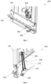
- Figures 1 and 1 show an end view of an embodiment of wagon 100 of the present disclosure.
- the wagon 100 of the present disclosure is an FTT type wagon which comprises a platform 110, two wagon bulkheads 120, a cover 130, a cover module 140, a cover movement system 200 and a cover locking system 300.
- Platform 110 and the bulkhead 120 form the fixed structure of this embodiment of the wagon 100.
- the cover module 140 in turn, associates with the cover 130 at one of the ends and associates with wagon 100 so as to move along the longitudinal axis on platform 110.
- the cover module 140 opens and closes the cover 130 and, consequently, allows or prevents the access to platform 110 of wagon 100.
- wagon 100 Although the embodiment of wagon 100 shown comprises the illustrated characteristics, other types of wagons can be used to implement the present invention. The same applies to the type of cover 130 described and shown.
- cover 130 In the context of the present disclosure, the expression "cover” 130 must not be comprised in a restrictive manner, but as different constructive alternatives for closing a wagon 100, such as a tarpaulin with accordion structure, a rigid sliding door, a movable scuttle, a top access window, among other options with similar purposes.
- cover module 140 which interacts with a platform 110 and a bulkhead 120 to close the wagon 100 of the illustrated embodiment
- present disclosure can be used in other contexts, such as in a sliding door which interacts with a wagon wall, or other equivalent examples.
- the cover movement system 200 is comprised within the cover module 140 of the wagon 100.
- the cover movement system 200 can further be comprised within the cover 130 itself.
- the cover module 140 of the wagon 100 is a rigid structure associated with at least one of the ends of the cover 130 of the wagon 100 and, commonly, with both ends of the cover 130 of the wagon 100.
- the cover movement system 200 provides an interaction between the cover 130 or the cover module 140 and the wagon 100 for the cover 130 and/or the module cover 140 to be moved in relation to the wagon 100.
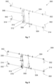
- FIGS 3 and 4 illustrate an embodiment of the cover movement system 200.
- the cover movement system 200 comprises a motor 202, an interaction element 204 and a transmission system 206.
- the motor 202 is associated with the interaction element 204 through the transmission system 206, whereby the interaction element 204 is configured to interact with the wagon 100 and to provide a movement of the cover 130 in relation to the wagon 100.
- the motor 202 is the component responsible for moving the cover movement system 200. When activated, the motor 202 moves the transmission system 206 and the interaction element 204, which in turn moves the cover 130. In one embodiment, the motor 202 is an electric motor. The power of the motor 202 is derived from batteries, solar panel and/or other means available in a wagon 100.
- the cover movement system 200 comprises the transmission system 206, which is associated with the motor 202 and with the interaction element 204.
- the motor 202 is associated with the interaction element 204 by means of the transmission system 206, as illustrated.
- the transmission system 206 is the component of the system responsible for transmitting the rotation of the motor 202 to the interaction element 204.
- the transmission system 206 comprises a driving gear 208 and a driven gear 210 connected by a belt 212.
- the driving gear 208 is the gear which associates with the motor 202 and the driven gear 210 is the gear which associates with the interaction element 204.
- the belt 212 moves and transfers the rotation to the driven gear 210 and, consequently, to the interaction element 204.
- the driving gear 208 comprises a smaller diameter than the diameter of the driven gear 210.
- the transmission system 206 increases the torque transferred from the motor 202 to the interaction element 204, reducing the necessary power of the motor 202 to move the cover 130 and facilitating the movement thereof.
- the interaction element 204 is the component responsible for receiving the rotation derived from the motor 202 and transmitting to a component of wagon 100 aiming at moving the cover 130 in relation to the wagon 100.
- the interaction element 204 is a gear configured to interact with a rack 150 that is longitudinally present in wagon 100.
- the rotation of motor 202 moves the transmission system 206, which turns the gear.
- the turning of the gear which interacts with the rack 150 moves the cover 130 along the longitudinal axis of the wagon 100.
- the cover movement system 200 further comprises an uncoupling device 220.
- the uncoupling device 220 is a component of the system which allows the coupling and uncoupling between the transmission system 206 and the interaction element 204.
- the cover movement system 200 of the present disclosure enables the change between an automatic movement of the cover 130, when the uncoupling device 220 is in the coupled mode, and manual, when the uncoupling device 220 is the uncoupled mode.
- Said possibility is particularly advantageous in an automatic system, since the motor 202 when stopped blocks or makes difficult the movement of the cover 130 in a manual manner, limiting the use of the systems which do not allow the uncoupling between the cover movement system 200 and the cover 130.
- the uncoupling device 220 illustrated in detail in Figures 5 and 6 , comprises an extension sleeve 222 which performs the coupling between the shaft of motor 202 and the shaft of the transmission system 206 - in this case, the driven gear 210.
- the movement of the extension sleeve 222 is carried out by a key 224 which fits into an orifice present in the uncoupling device 220.
- the key 224 can be, for example, a key 224 already used in wagon 100 for other systems (for example, for activating the electric system), thus reducing the complexity and number of components of wagon 100.
- the extension sleeve 222 positions itself so as to interact both with the shaft 228 of the driven gear 210 as with the shaft 226 of the interaction element 204, thus performing the transmission of the rotation from one shaft to the other.
- the extension sleeve 222 positions itself so as to interact only with the shaft 228 of the driven gear 210 but does not interact with the shaft 226 of the interaction element 204, uncoupling the shaft 226 of the interaction element 204 of the cover movement system 200.
- the cover movement system 200 may not comprise the transmission system 206.
- the motor 202 associates directly with the interaction element 204 and the uncoupling device 220 promotes the coupling/uncoupling between the shaft of the motor 202 and the shaft 226 of the interaction element 204.
- FIGS 7 and 8 illustrate an embodiment of the locking system of the cover 300 of the present embodiment in the locked and unlocked positions.
- the locking system of the cover 300 comprises at least one locking element 302, at least one locking shaft 304 and an automatic driver 306.
- the locking system of the cover 300 comprises four locking elements 302, two locking shafts, an automatic driver 306, a connecting element 308 and a manual driver 314.
- the locking element 302 is the component responsible for associating with a locking handle 142 of the cover 130 or of the cover module 140. In this manner, by interacting with the locking handle 142, the locking element 302 prevents the opening of the cover 130 of the wagon 100.
- the locking element 302 comprises a hook shape. In this case, when the hook interacts with the locking handle 142 the movement of cover 130 is mechanically prevented from being carried out.
- a hook shape is shown, other shapes can be used to obtain the same technical effect.
- the locking element 302 is arranged at the end of the locking shaft 304, or further, the locking elements 302 are arranged at each of the ends of the locking shafts. Thus, from the rotation of the locking shafts, the locking elements 302 move to lock or unlock the cover 130.
- the locking shafts are configured to transmit the movement of the automatic driver 306 to the locking elements 302.
- at least one of the locking shafts comprises a shaft gear 312 which interacts with a component of the automatic driver 306, as will be described ahead.
- the connecting element 308 is a pin connected to the sleeve extensions, configured to transform the linear movement of the pin into a circular movement of the locking shafts.
- the automatic driver 306 is the component responsible for moving the system. Upon being activated, the automatic driver 306 moves the locking shafts and, consequently, the locking elements 302 to lock or unlock the cover 130 of the wagon 100.
- the automatic driver 306 of the illustrated embodiment is a pneumatic driver. However, other types of drivers can be used, such as a hydraulic driver or step motor.
- the automatic driver 306 comprises a rack 310, or similar element, configured to interact with the locking shaft 304 by means of the shaft gear 312. The interaction of the rack 310 of the automatic driver 306 with the shaft gear 312 transforms the linear movement of the automatic driver 306 into shaft rotation. Consequently, the driving of the automatic driver 306 promotes the movement of the locking elements 302 and, in this way, the locking or unlocking of the cover 130 of the wagon 100.
- the cover locking system 300 further comprises the manual driver 314.
- the manual driver 314 is the component of the system which allows the locking or unlocking of the cover 130 to be made in a manual way.
- the locking system of the cover 300 of the present invention reaches the advantageous technical effect of enabling the locking or unlocking of the cover 130 to be performed in an automatic way through the automatic driver 306, or in a manual way, through the manual driver 314.
- the manual driver 314 shown is a clasp comprised at the ends of the locking shafts.
- the clasp is configured to be manually handled by an operator and enables the movement of the system in an independent manner from the automatic driver 306.
- the use of the system of the present invention is not limited to automatic means.
- FIGS 9, 10 and 11 illustrate different views of the wagon 100 of the present embodiment to facilitate visualizing some of the characteristics and the general understanding of the wagon 100 comprising the systems described.
- wagon 100 of the present disclosure further comprises a logic driver which controls the cover movement system 200 and the cover locking system 300 in an integrated manner.
- the logic driver is a component responsible for driving motor 202 of the cover movement system 200 and the automatic driver 306 of the cover locking system 300 at specific moments according to a predefined operational sequence. Said operational sequence can be defined according to the needs of each project and the need for use, making it possible to define one or more sequences of interest.
- the logic driver comprises the following steps for the closing of cover 130 of wagon 100: driving the motor 202 of the cover movement system 200 until the cover module 140 interacts with the bulkhead 120 of wagon 100; and driving the automatic driver 306 of the cover locking system 300 until the interaction between the locking element 302 and the locking handle 142 locks the movement of the cover module 142 in relation to wagon 100.
- the logic driver comprises the following steps for the opening of cover 130 of wagon 100; driving the automatic driver 306 of the cover locking system 300 until there is no interaction between the locking element 302 and the locking handle 142 for unlocking the cover module 140; driving the motor 202 of the cover movement system 200 in the direction of the opening of cover 130 until the desired position is reached in the cover module140.
- the present disclosure describes a movement system for wagon cover 200 that comprises a motor 202 associated with an interaction element 204 configured to interact with a wagon 100 and move a cover 130. It further refers to a wagon cover locking system 300 that comprises at least one shaft 304 and at least one locking element 302 associated with the shaft 304 and configured to fit within a wagon 100 cover 130.
Landscapes
- Engineering & Computer Science (AREA)
- Mechanical Engineering (AREA)
- Transportation (AREA)
- Power-Operated Mechanisms For Wings (AREA)
Priority Applications (1)
| Application Number | Priority Date | Filing Date | Title |
|---|---|---|---|
| EP23196113.7A EP4520617A1 (de) | 2023-09-07 | 2023-09-07 | Bewegungs- und verriegelungssystem für einen wagendeckel |
Applications Claiming Priority (1)
| Application Number | Priority Date | Filing Date | Title |
|---|---|---|---|
| EP23196113.7A EP4520617A1 (de) | 2023-09-07 | 2023-09-07 | Bewegungs- und verriegelungssystem für einen wagendeckel |
Publications (1)
| Publication Number | Publication Date |
|---|---|
| EP4520617A1 true EP4520617A1 (de) | 2025-03-12 |
Family
ID=88647411
Family Applications (1)
| Application Number | Title | Priority Date | Filing Date |
|---|---|---|---|
| EP23196113.7A Pending EP4520617A1 (de) | 2023-09-07 | 2023-09-07 | Bewegungs- und verriegelungssystem für einen wagendeckel |
Country Status (1)
| Country | Link |
|---|---|
| EP (1) | EP4520617A1 (de) |
Citations (13)
| Publication number | Priority date | Publication date | Assignee | Title |
|---|---|---|---|---|
| DE74760C (de) * | 1893-06-09 | 1894-04-24 | A. OECHSLE in Neu-Ulm, Marienstrafse 9 | Eisenbahnwagen mit horizontal ausziehbarem Kasten zum Verladen von Heu und dergleichen. |
| GB635410A (en) | 1952-07-28 | 1950-04-12 | Thomas Hulmes | Improvements in or relating to a closing tool for wagon doors |
| GB2199549A (en) * | 1986-12-30 | 1988-07-13 | Philip Peter Davis | Retractable cover for vehicle load platforms |
| DE19644573A1 (de) * | 1996-10-26 | 1998-04-30 | Abb Henschell Ag | Antrieb für Planenabdeckung |
| KR20040009911A (ko) * | 2002-07-26 | 2004-01-31 | 주식회사 고려차량 | 화차덮개의 록킹장치 |
| EP1529671A2 (de) * | 2003-11-07 | 2005-05-11 | Ambrogio Lippolis | Cabrio Abdeckung für Lastwagen |
| US20060103139A1 (en) * | 2004-11-12 | 2006-05-18 | Fahrzeugtechnik Dessau Ag | Locking and unlocking device for vehicle doors, in particular swinging sliding doors for rail vehicles |
| EP1820713A1 (de) | 2006-02-16 | 2007-08-22 | Société Nationale des Chemins de Fer Français | Faltbares Abdecksystem verschiebbar geführt auf ein Hydraulikzylinder |
| CN101797925A (zh) * | 2010-03-29 | 2010-08-11 | 南车眉山车辆有限公司 | 一种活动车顶锁闭装置 |
| WO2011017859A1 (zh) * | 2009-08-14 | 2011-02-17 | 齐齐哈尔轨道交通装备有限责任公司 | 铁路货车顶盖装置及具有该顶盖装置的粮食漏斗车 |
| CN107503594A (zh) * | 2017-09-04 | 2017-12-22 | 宁波生久柜锁有限公司 | 铁路机械冷藏侧门转把锁闭机构 |
| CN209813984U (zh) * | 2018-12-11 | 2019-12-20 | 中国铁建高新装备股份有限公司 | 一种自动伸缩式防护罩 |
| CN114670880A (zh) * | 2022-03-18 | 2022-06-28 | 中车太原机车车辆有限公司 | 一种铁路漏斗车对开式顶盖开闭装置 |
-
2023
- 2023-09-07 EP EP23196113.7A patent/EP4520617A1/de active Pending
Patent Citations (13)
| Publication number | Priority date | Publication date | Assignee | Title |
|---|---|---|---|---|
| DE74760C (de) * | 1893-06-09 | 1894-04-24 | A. OECHSLE in Neu-Ulm, Marienstrafse 9 | Eisenbahnwagen mit horizontal ausziehbarem Kasten zum Verladen von Heu und dergleichen. |
| GB635410A (en) | 1952-07-28 | 1950-04-12 | Thomas Hulmes | Improvements in or relating to a closing tool for wagon doors |
| GB2199549A (en) * | 1986-12-30 | 1988-07-13 | Philip Peter Davis | Retractable cover for vehicle load platforms |
| DE19644573A1 (de) * | 1996-10-26 | 1998-04-30 | Abb Henschell Ag | Antrieb für Planenabdeckung |
| KR20040009911A (ko) * | 2002-07-26 | 2004-01-31 | 주식회사 고려차량 | 화차덮개의 록킹장치 |
| EP1529671A2 (de) * | 2003-11-07 | 2005-05-11 | Ambrogio Lippolis | Cabrio Abdeckung für Lastwagen |
| US20060103139A1 (en) * | 2004-11-12 | 2006-05-18 | Fahrzeugtechnik Dessau Ag | Locking and unlocking device for vehicle doors, in particular swinging sliding doors for rail vehicles |
| EP1820713A1 (de) | 2006-02-16 | 2007-08-22 | Société Nationale des Chemins de Fer Français | Faltbares Abdecksystem verschiebbar geführt auf ein Hydraulikzylinder |
| WO2011017859A1 (zh) * | 2009-08-14 | 2011-02-17 | 齐齐哈尔轨道交通装备有限责任公司 | 铁路货车顶盖装置及具有该顶盖装置的粮食漏斗车 |
| CN101797925A (zh) * | 2010-03-29 | 2010-08-11 | 南车眉山车辆有限公司 | 一种活动车顶锁闭装置 |
| CN107503594A (zh) * | 2017-09-04 | 2017-12-22 | 宁波生久柜锁有限公司 | 铁路机械冷藏侧门转把锁闭机构 |
| CN209813984U (zh) * | 2018-12-11 | 2019-12-20 | 中国铁建高新装备股份有限公司 | 一种自动伸缩式防护罩 |
| CN114670880A (zh) * | 2022-03-18 | 2022-06-28 | 中车太原机车车辆有限公司 | 一种铁路漏斗车对开式顶盖开闭装置 |
Similar Documents
| Publication | Publication Date | Title |
|---|---|---|
| US10005498B2 (en) | Hatch actuation unit of a motor vehicle | |
| CN114901916B (zh) | 机动车门锁系统 | |
| US6457674B2 (en) | Method and device for closing a door of an aircraft | |
| US20090107048A1 (en) | Opening/closing apparatus for vehicle | |
| DE60004794T2 (de) | Motorisch angetriebene fahrzeugschiebetür | |
| CN116601069B (zh) | 自动列车耦连装置 | |
| US20050039404A1 (en) | Drive assembly for a power closure panel | |
| CN113829870B (zh) | 用于关闭机动车辆的车身的加燃料口的关闭组件 | |
| CA3037624A1 (en) | Electric door opener for multi-door trailer | |
| US3266328A (en) | Driving device for a sliding roof | |
| EP4520617A1 (de) | Bewegungs- und verriegelungssystem für einen wagendeckel | |
| US20230374842A1 (en) | Overload Clutch for an Actuator for Driving Components of a Loading, Fueling or Service Door, and Actuating Mechanism for Operating a Loading, Fueling or Service Door Including such an Overload Clutch | |
| FI65589C (fi) | Propelleranordning foer ett fartyg | |
| US20200157856A1 (en) | Power Child Lock System for Vehicle | |
| EP1898514B1 (de) | Ansteuerungsvorrichtung für ein offenes/geschlossenes Element | |
| EP1738993A2 (de) | Antrieb zum Verschwenken einer an eine Karosserie eines Fahrzeugs angeordneten Klappe | |
| KR20210125416A (ko) | 이중 변환 플러그형 승객 출입문 | |
| CZ2001284A3 (cs) | Samočinně rozpojitelná jednotka spojky zámku automobilových dveří | |
| CN107476682A (zh) | 一种车用微型自动落锁解锁执行器 | |
| US20060066114A1 (en) | Door handle input decoupler for a cinching latch actuator | |
| US20250163974A1 (en) | Overload Clutch for an Actuating Mechanism for Actuating a Loading, Tank or Service Flap and Actuating Mechanism with such an Overload Clutch and Actuating Mechanism Having such an Overload Coupling | |
| DE19755942C2 (de) | Fahrzeugtür | |
| KR20090075406A (ko) | 자동차 운반선용 카데크의 자동 스토퍼장치 | |
| EP1310681B1 (de) | Linearantrieb mit innerer mechanischer Verriegelung | |
| US7540207B2 (en) | Device for actuating the doors of vehicles |
Legal Events
| Date | Code | Title | Description |
|---|---|---|---|
| PUAI | Public reference made under article 153(3) epc to a published international application that has entered the european phase |
Free format text: ORIGINAL CODE: 0009012 |
|
| STAA | Information on the status of an ep patent application or granted ep patent |
Free format text: STATUS: THE APPLICATION HAS BEEN PUBLISHED |
|
| AK | Designated contracting states |
Kind code of ref document: A1 Designated state(s): AL AT BE BG CH CY CZ DE DK EE ES FI FR GB GR HR HU IE IS IT LI LT LU LV MC ME MK MT NL NO PL PT RO RS SE SI SK SM TR |
|
| STAA | Information on the status of an ep patent application or granted ep patent |
Free format text: STATUS: REQUEST FOR EXAMINATION WAS MADE |
|
| 17P | Request for examination filed |
Effective date: 20250910 |