EP4520649A1 - Procédé et appareil de commande de l'amarrage ou du désamarrage automatique d'un navire - Google Patents
Procédé et appareil de commande de l'amarrage ou du désamarrage automatique d'un navire Download PDFInfo
- Publication number
- EP4520649A1 EP4520649A1 EP23913044.6A EP23913044A EP4520649A1 EP 4520649 A1 EP4520649 A1 EP 4520649A1 EP 23913044 A EP23913044 A EP 23913044A EP 4520649 A1 EP4520649 A1 EP 4520649A1
- Authority
- EP
- European Patent Office
- Prior art keywords
- ship
- berthing
- destination
- docking
- point
- Prior art date
- Legal status (The legal status is an assumption and is not a legal conclusion. Google has not performed a legal analysis and makes no representation as to the accuracy of the status listed.)
- Pending
Links
Images


Classifications
-
- B—PERFORMING OPERATIONS; TRANSPORTING
- B63—SHIPS OR OTHER WATERBORNE VESSELS; RELATED EQUIPMENT
- B63B—SHIPS OR OTHER WATERBORNE VESSELS; EQUIPMENT FOR SHIPPING
- B63B79/00—Monitoring properties or operating parameters of vessels in operation
- B63B79/40—Monitoring properties or operating parameters of vessels in operation for controlling the operation of vessels, e.g. monitoring their speed, routing or maintenance schedules
-
- G—PHYSICS
- G05—CONTROLLING; REGULATING
- G05D—SYSTEMS FOR CONTROLLING OR REGULATING NON-ELECTRIC VARIABLES
- G05D1/00—Control of position, course, altitude or attitude of land, water, air or space vehicles, e.g. using automatic pilots
- G05D1/60—Intended control result
- G05D1/656—Interaction with payloads or external entities
- G05D1/661—Docking at a base station
-
- B—PERFORMING OPERATIONS; TRANSPORTING
- B63—SHIPS OR OTHER WATERBORNE VESSELS; RELATED EQUIPMENT
- B63H—MARINE PROPULSION OR STEERING
- B63H25/00—Steering; Slowing-down otherwise than by use of propulsive elements; Dynamic anchoring, i.e. positioning vessels by means of main or auxiliary propulsive elements
- B63H25/02—Initiating means for steering, for slowing down, otherwise than by use of propulsive elements, or for dynamic anchoring
- B63H25/04—Initiating means for steering, for slowing down, otherwise than by use of propulsive elements, or for dynamic anchoring automatic, e.g. reacting to compass
-
- B—PERFORMING OPERATIONS; TRANSPORTING
- B63—SHIPS OR OTHER WATERBORNE VESSELS; RELATED EQUIPMENT
- B63B—SHIPS OR OTHER WATERBORNE VESSELS; EQUIPMENT FOR SHIPPING
- B63B43/00—Improving safety of vessels, e.g. damage control, not otherwise provided for
- B63B43/18—Improving safety of vessels, e.g. damage control, not otherwise provided for preventing collision or grounding; reducing collision damage
- B63B43/20—Feelers
-
- B—PERFORMING OPERATIONS; TRANSPORTING
- B63—SHIPS OR OTHER WATERBORNE VESSELS; RELATED EQUIPMENT
- B63B—SHIPS OR OTHER WATERBORNE VESSELS; EQUIPMENT FOR SHIPPING
- B63B79/00—Monitoring properties or operating parameters of vessels in operation
- B63B79/10—Monitoring properties or operating parameters of vessels in operation using sensors, e.g. pressure sensors, strain gauges or accelerometers
-
- B—PERFORMING OPERATIONS; TRANSPORTING
- B63—SHIPS OR OTHER WATERBORNE VESSELS; RELATED EQUIPMENT
- B63B—SHIPS OR OTHER WATERBORNE VESSELS; EQUIPMENT FOR SHIPPING
- B63B79/00—Monitoring properties or operating parameters of vessels in operation
- B63B79/30—Monitoring properties or operating parameters of vessels in operation for diagnosing, testing or predicting the integrity or performance of vessels
-
- B—PERFORMING OPERATIONS; TRANSPORTING
- B63—SHIPS OR OTHER WATERBORNE VESSELS; RELATED EQUIPMENT
- B63H—MARINE PROPULSION OR STEERING
- B63H25/00—Steering; Slowing-down otherwise than by use of propulsive elements; Dynamic anchoring, i.e. positioning vessels by means of main or auxiliary propulsive elements
- B63H25/42—Steering or dynamic anchoring by propulsive elements; Steering or dynamic anchoring by propellers used therefor only; Steering or dynamic anchoring by rudders carrying propellers
-
- G—PHYSICS
- G01—MEASURING; TESTING
- G01C—MEASURING DISTANCES, LEVELS OR BEARINGS; SURVEYING; NAVIGATION; GYROSCOPIC INSTRUMENTS; PHOTOGRAMMETRY OR VIDEOGRAMMETRY
- G01C21/00—Navigation; Navigational instruments not provided for in groups G01C1/00 - G01C19/00
- G01C21/20—Instruments for performing navigational calculations
- G01C21/203—Instruments for performing navigational calculations specially adapted for water-borne vessels
-
- G—PHYSICS
- G05—CONTROLLING; REGULATING
- G05D—SYSTEMS FOR CONTROLLING OR REGULATING NON-ELECTRIC VARIABLES
- G05D1/00—Control of position, course, altitude or attitude of land, water, air or space vehicles, e.g. using automatic pilots
- G05D1/60—Intended control result
- G05D1/606—Compensating for or utilising external environmental conditions, e.g. wind or water currents
-
- G—PHYSICS
- G08—SIGNALLING
- G08G—TRAFFIC CONTROL SYSTEMS
- G08G3/00—Traffic control systems for marine craft
-
- B—PERFORMING OPERATIONS; TRANSPORTING
- B63—SHIPS OR OTHER WATERBORNE VESSELS; RELATED EQUIPMENT
- B63H—MARINE PROPULSION OR STEERING
- B63H25/00—Steering; Slowing-down otherwise than by use of propulsive elements; Dynamic anchoring, i.e. positioning vessels by means of main or auxiliary propulsive elements
- B63H25/02—Initiating means for steering, for slowing down, otherwise than by use of propulsive elements, or for dynamic anchoring
- B63H2025/026—Initiating means for steering, for slowing down, otherwise than by use of propulsive elements, or for dynamic anchoring using multi-axis control levers, or the like, e.g. joysticks, wherein at least one degree of freedom is employed for steering, slowing down, or dynamic anchoring
-
- G—PHYSICS
- G05—CONTROLLING; REGULATING
- G05D—SYSTEMS FOR CONTROLLING OR REGULATING NON-ELECTRIC VARIABLES
- G05D2105/00—Specific applications of the controlled vehicles
- G05D2105/20—Specific applications of the controlled vehicles for transportation
- G05D2105/22—Specific applications of the controlled vehicles for transportation of humans
-
- G—PHYSICS
- G05—CONTROLLING; REGULATING
- G05D—SYSTEMS FOR CONTROLLING OR REGULATING NON-ELECTRIC VARIABLES
- G05D2107/00—Specific environments of the controlled vehicles
- G05D2107/80—Transportation hubs
- G05D2107/84—Harbours
-
- G—PHYSICS
- G05—CONTROLLING; REGULATING
- G05D—SYSTEMS FOR CONTROLLING OR REGULATING NON-ELECTRIC VARIABLES
- G05D2109/00—Types of controlled vehicles
- G05D2109/30—Water vehicles
- G05D2109/34—Water vehicles operating on the water surface
-
- G—PHYSICS
- G08—SIGNALLING
- G08G—TRAFFIC CONTROL SYSTEMS
- G08G3/00—Traffic control systems for marine craft
- G08G3/02—Anti-collision systems
Definitions
- the present disclosure relates to a control apparatus and control method for berthing or unberthing a ship.
- the present disclosure has been made in recognition of at least one of the needs or conventional problems that arise when unberthing or berthing of ships as described above.
- One aspect of the present disclosure is to solve the problems of conventional unberthing or berthing technology of ships by using a plurality of sensors and an algorithm for automatically controlling unberthing or berthing of ships.
- One aspect of the present disclosure is to solve the problems of the conventional ship berthing technology by adjusting a location and posture of a ship using dynamic positioning (DP) and then performing docking by controlling the ship according to a guidance path.
- DP dynamic positioning
- a control method for autonomously berthing a ship using dynamic positioning including obtaining ship state information and berth information, setting a first destination adjacent to a berthing region based on the ship state information and the berth information, and controlling a ship to move to the first destination and adjust a location and posture to correspond to the first destination.
- controlling the ship may include an approaching operation of controlling the ship to approach the first destination and a dynamic positioning operation of adjusting the location and posture of the ship based on an error rate between the first destination and a current location of the ship.
- control method may further include generating a guidance path in the form of a linear function or a quadratic function, with a start point being the first destination and an end point being a second destination included in the berthing region, based on a center point of the ship and a docking operation of controlling the ship to move along the guidance path.
- control method may further include determining the berthing region based on sensing information received from at least one of a camera sensor and a light detection and ranging (LiDAR) sensor attached to the ship and providing an interface displaying the berthing region.
- LiDAR light detection and ranging
- the docking operation may include calculating a docking success rate of the ship and transitioning to a recovery operation, when the docking success rate is less than or equal to a preset threshold.
- the docking success rate may be a value determined based on a safety envelope or a domain
- the safety envelope may be a quadratic function curve generated on both sides of the guidance path
- the domain may be an ellipse determined with a major axis determined based on an overall length of the ship and a minor axis determined based on a length of the ship in a width direction.
- the recovery operation may include setting a recovery point to offset an influence of a disturbance and controlling the ship to move to the recovery point.
- the setting the recovery point may include setting the recovery point based on at least one of a location of the ship immediately after entering the recovery operation and a minimum distance over which a safety envelope does not overlap a berth.
- the recovery operation further may include transitioning back to the docking operation when the docking success rate recovers to a preset value or greater.
- the calculating the docking success rate of the ship may include calculating a docking risk based on one or more of a relative distance risk with respect to the safety envelope invading the domain, a relative speed risk with respect to the safety envelope invading the domain, a risk for a distance over which the ship deviates from the guidance path, and a risk of a distance over which a stern of the ship deviates based on a berth located in a mooring direction and calculating the docking success rate based on the docking risk.
- the setting the first destination may include calculating the first destination based on at least one of a location (left/right) of the berth with respect to the ship, a mooring direction (PORT/STBD) of the ship, and a size (L, B) of the ship.
- the setting the first destination may further include compensating for the first destination in an opposite direction in which wind or current acts.
- the dynamic positioning operation may include calculating an error rate between a current location and heading of the ship based on the first destination and a first target heading when the ship approaches the first destination within a preset distance radius, generating a control command to adjust the location and posture of the ship based on the error rate, and determining that the ship is stabilized at the first destination and transitioning to a docking operation, when the error rate is less than or equal to a preset value.
- a control apparatus for autonomously berthing a ship using dynamic positioning including a processor and a control module configured to operate according to an operation control command from the processor, wherein the processor is configured to generate an approaching operation control command to obtain ship state information and berth information, set a first destination, and control the ship to approach the first destination, generate a dynamic positioning operation control command to adjust a location and posture of the ship based on an error rate between the first destination and a current location, generate a guidance path with a start point being the first destination and an end point being a second destination, based on a center point of the ship, and generate a docking operation control command to control the ship to move along the guidance path.
- control apparatus may further include an input/output device, wherein the processor may be configured to determine the second destination based on a user input obtained using the input/output device, display the guidance path using the input/output device, and generate, when a user control input related to control of the ship is received using the input/output device, an operation control command based on the user control input.
- a recovery point that may offset the disturbance may be set and the ship may be controlled to move to the recovery point, thereby providing an automatic berthing method that is robust to the disturbance.
- Some embodiments of the present disclosure may be described in terms of functional block components and various processing phases. Such functional blocks may be realized by any number of hardware and/or software components configured to perform the specified functions.
- the functional blocks of the present disclosure may be implemented by one or more microprocessors or may be implemented by circuit components for certain functions.
- functional blocks of the present disclosure may be implemented in various programming or scripting languages.
- Functional blocks may be implemented as algorithms running on one or more processors.
- the present disclosure may employ conventional technologies for electronic environment setup, signal processing, and/or data processing. Terms, such as “mechanism, " "element,” “means,” and “configuration” may be used broadly and are not limited to mechanical and physical components.
- connecting lines, or connectors shown in the drawing are intended to represent exemplary functional relationships and/or physical or logical couplings between the various elements. It should be noted that many alternative or additional functional relationships, physical connections or logical connections may be present in a practical device.
- any one part is connected with the other part includes a case in which the parts are directly connected with each other and a case in which the parts are electrically connected with each other with other elements located therebetween.
- FIG. 1 is a block diagram illustrating a control apparatus 1000 for autonomously berthing or unberthing a ship according to an embodiment of the present disclosure.
- the control apparatus 1000 for unberthing or berthing a ship may include a sensor 1200, and I/O (I/O) device 1300, an autonomous navigation controller 1400, and a ship steering device 1500.
- I/O I/O
- the senor 1200 may include a camera, a radio detection and ranging (RADAR), a light detection and ranging (LiDAR), a global positioning system (GPS), an automatic identification system (AIS), Sonar, an inertial measurement unit (IMU) but is not limited the examples above.
- RADAR radio detection and ranging
- LiDAR light detection and ranging
- GPS global positioning system
- AIS automatic identification system
- Sonar Sonar
- IMU inertial measurement unit
- the I/O device 1300 may include an input device that obtains a user input and an output device that outputs information to be provided to a user.
- the input device may include a computing device including a rudder controller, steering wheel, pedal, joystick, steering button, and a touch screen interface
- the output device may a visual output device, such as a monitor or head-up display, and an auditory output device, such as a speaker, but is not limited to the examples described above.
- the autonomous navigation controller 1400 may obtain ship state information and berth information, sets a dynamic positioning (DP) point based on the ship state information and berth information, and control the ship to move to the DP point and perform DP operation.
- the DP point may be a point adjacent to a berthing region.
- the DP point may be referred to as a first destination or a preliminary destination.
- the DP point may be a point at which the ship is slowed down or stopped before performing a docking operation to locate the ship within a determined berthing region.
- the autonomous navigation controller 1400 may control the ship to perform a docking operation of moving along a guidance path and control the ship to perform a recovery operation that may compensate for disturbance when performing the docking operation. Detailed operations of the autonomous navigation controller 1400 are described below.
- a ship steering device 1500 may include a ship steering device that operates according to control commands from the processor 1300.
- the ship steering device 1500 may include a rudder, an engine, a turbine, an electric propulsion device, etc. but is not limited to the aforementioned example.
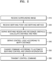
- FIG. 2 is a flowchart of a control method for unberthing or berthing a ship according to an embodiment of the present disclosure.
- the autonomous navigation controller 1400 receives information (e.g., images around the ship, distance to a certain object or obstacle, location of the ship, etc.) necessary for autonomous navigation from the sensor 1200 (210).
- the received sensing information is integrated and displayed on the I/O device 1300, and the autonomous navigation controller 1400 receives a berthing point and berthing method input from a driver through the I/O device 1300 (220).
- the berthing point and berthing method may be input through the touch screen.
- location information of the corresponding berthing point may be transmitted to the autonomous navigation controller 1400.
- the berthing method may be selected by the user depending on the berthing location and the type of ship.
- the berthing method may be selected from front berthing, rear berthing, and side berthing, and finally, a direction in which a person gets off by attaching the ship may be selected.
- the autonomous navigation controller 1400 may determine the berthing region near the berthing point based on the sensing information and the input berthing conditions (e.g., a berth location, berthing method, etc.) and determine the presence or absence of an obstacle around the ship (230).
- the berthing point may be a final docking target point at which the ship finally wants to anchor based on the center point of the ship
- the berthing region may refer to a spatial region in which the ship may be located in consideration of the posture of the ship when the ship is anchored at the berthing point.
- the berthing point may be a point included within the berthing region.
- the berthing point may be the center point of the berthing point.
- the berthing point may be a point at which the center point of the ship is located when the ship is located within the berthing point.
- the berthing point may be referred to as a second destination.
- the autonomous navigation controller 1400 may recognize one or more available berthing regions based on the sensor 1200 attached to the ship, accurately derive a berth location from the user-designated or automatically designated berthing region, and calculate a distance from the current ship to the berth location and berthing region.
- the sensor 1200 may be a camera sensor 110 or a LiDAR sensor 1110 as shown in FIG. 16 , which is described below.
- the sensor 1200 may calculate a risk by recognizing an obstacle around the ship.
- a relative location between the berthing region and the ship may be determined.
- a movement route may be set by generating a map using the relative location of the berthing region and the ship.
- a GPS error may be corrected to derive an exact location of the ship, an obstacle in the movement path may be detected, and when an obstacle is detected, safe berthing may be performed by avoiding the obstacle.
- the autonomous navigation controller 1400 may determine a control logic according to a berth distance, which is a distance from the center of the ship to the center of the berthing region (240). In an embodiment of the present disclosure, the autonomous navigation controller 1400 may determine a ship control command for automatic berthing using the calculated distance information to the berthing region and risk information.
- FIG. 3 is a flowchart illustrating a phase of determining a control command according to control logic in the control method for unberthing or berthing a ship according to an embodiment of the present disclosure.
- the autonomous navigation controller 1400 may generate a curved path so that the ship may safely approach a final berthing point and berth (310) and calculate a guidance law not to deviate significantly from the curved path (320).
- the guidance law refers to a movement direction and speed value of the ship.
- the movement direction is determined as a total of six directions: forward, backward, port, starboard, clockwise, and counterclockwise.
- a DP command may be issued for the ship to fix a location thereof in place.
- the DP command may control the ship to maintain the current location and a heading angle. If an obstacle or dangerous situation is detected around the ship (340) while automatic berthing control is being performed (330), the ship may immediately perform control according to the DP command to fix the location in place (350), and after a risk is eliminated, the ship may perform automatic berthing control subsequently.
- the DP command and DP point setting may be used to first fix the location and then start docking in order to stably perform berthing during the automatic berthing process.
- the DP command and DP point setting according to a second embodiment of the present disclosure are described with reference to FIG. 7 below.
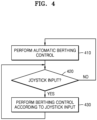
- FIG. 4 is a flowchart illustrating a phase of changing a control command according to driver intervention in a control method for unberthing or berthing a ship according to an embodiment of the present disclosure.
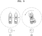
- FIG. 5 is a diagram illustrating a method of controlling movement of a ship using a joystick according to an embodiment of the present disclosure.
- An example shown on the left in FIG. 5 shows a case in which the ship is controlled to move to starboard when the joystick is moved to the right, and an example shown on the right in FIG. 5 shows a case in which the ship is also controlled to move to turn counterclockwise when the joystick is moved counterclockwise.
- the ship when the ship turns in place, the ship may be controlled by aligning the steering (or engine) in parallel in a 11 shape.
- the movement of the joystick and the ship shown in FIG. 5 is only an example, and the movement of the joystick and the ship may move differently depending on what is defined in advance.
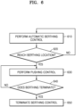
- FIG. 6 is a flowchart of a control method for unberthing or berthing a ship according to an embodiment of the present disclosure.
- control pumping
- a passenger disembarks 630
- the ship is tied with a rope, and then, when a berthing end button on a mobile device is pressed (640), all sequences of berthing control are terminated (650).
- unberthing or berthing control of the ship is automatically performed, thereby enabling users who are inexperienced in driving or handling a ship to easily operate the ship.
- the possibility of accidents that may occur during unberthing or berthing of the ship may be significantly reduced, and because only the engine mounted on the ship is controlled, equipment, such as a separate thruster for control, is not necessary, and thus, the structure of the ship may be simplified and the costs may be reduced.
- the driver may intervene through the joystick or mobile device at any time. Once driver intervention terminates, automatic unberthing or berthing control may be resumed by the autonomous navigation system, thereby implementing a high level of human and machine interface and cooperation.
- FIG. 7 an embodiment of autonomous berthing control of the ship by setting and using a DP point to stably perform autonomous berthing is mainly described.
- the embodiments starting from FIG. 7 do not conflict with FIGS. 1 to 6 , and of course, all embodiments described in this specification may be organically combined with each other.
- FIG. 7 is a flowchart illustrating a control method for autonomous berthing using dynamic positioning in a time series manner according to an embodiment of the present disclosure.
- the control method for autonomous berthing shown in FIG. 7 and FIG. 8 may be performed by the autonomous navigation controller 1400 of FIG. 1 described above, but without being limited thereto, the control method for autonomous berthing may also be performed by a certain processor included in the control apparatus for autonomous berthing of the present disclosure.
- the autonomous navigation controller 1400 obtains a user input through a user input device (710).
- the processor 1400 provides an application for obtaining a user input and may obtain a user input related to docking through the application.
- the types of user input related to docking may be one or more of a berth location, a berthing region, a docking method (any one of front docking, rear docking, and side docking), a mooring direction (port, starboard), and a docking start command.
- the autonomous navigation controller 1400 may finally determine a berthing point at which the ship is to anchor based on a center point of the ship based on birth information recognized in real time based on sensing information received from the sensor 1200 or information previously stored by the user.
- the autonomous navigation controller 1400 may determine, as a berthing region, a spatial region in which the ship may be located, taking into account the posture of the ship when anchored.
- the autonomous navigation controller 1400 may generate bounding box information that may mask the berthing region related to the berthing point determined based on the sensing information received from the sensor 1200 on a real-time camera image and transmit the generated bounding box information to an output device of the I/O device 1300. That is, the autonomous navigation controller 1400 may provide a berthing location display interface so that the berthing point or berthing region of the ship may be identified on the camera image.
- the autonomous navigation controller 1400 may automatically recognize one or more available berthing regions using the sensing information from the sensor 1200 and display the recognized berthing regions as bounding boxes on a monitor screen. That is, the autonomous navigation controller 1400 may provide a display that provides information on the berthing region and may determine an exact berthing region and berthing point based on the user's selection input for the berthing region.
- the autonomous navigation controller 1400 obtains current ship state information and berth information (720).
- the ship state information may include information related to a location, speed, and posture of the ship.
- the ship state information may be obtained from user input or the sensor 1200.
- the berth information may include information related to a location of a berth, a distance between the ship and the berth, a direction (left/fight) of the berth, a shape of the berth, and a berthable region formed by the berth.
- the autonomous navigation controller 1400 sets a DP point, approaches the DP point, and generates a guidance path for the docking described above (730).
- the DP point is a location at which the ship is fixed without moving in place. Ships do not have brakes, so the ship may stop at the DP point and start berthing in a stable state and move along the guidance path. Phase 730 is described in more detail in an approaching phase 851 of FIG. 8 .
- the autonomous navigation controller 1400 adjusts the location and posture of the ship on the DP point (740).
- Phase 740 is described in more detail in the dynamic positioning phase 852 of FIG. 8 .
- the autonomous navigation controller 1400 generates a guidance path in the form of a linear function or a quadratic function, with a start point being the DP point and an end point being the berthing point, based on the center point of the ship and controls the ship to move along the guidance path (750).
- Phase 750 is described in more detail in a docking phase 853 of FIG. 8 .
- the DP point may be described as a primary destination and the berthing point may be described as a secondary destination.
- phase 750 (docking phase) a docking SR (SR) is calculated in real time, and if the docking SR is below a preset value, a recovery point is set and the ship moves to the recovery point and adjusts the location and posture (770).
- Phase 770 is described in more detail in a recovery phase 854 of FIG. 8 .
- the autonomous navigation controller 1400 generates a movement control command for the ship (780) and completes docking of the ship.
- FIG. 8 is a diagram illustrating each phase of the autonomous docking method according to an embodiment of the present disclosure.
- the autonomous berthing method of the present disclosure may include the approaching phase (851), the dynamic positioning phase (852), the docking phase (853), and the recovery phase (854).
- the approaching phase (851) the dynamic positioning phase (852), the docking phase (853), and the recovery phase (854).
- the recovery phase 854
- a user input is obtained (810), it is determined to start autonomous berthing mode (820), and ship state information is obtained (880).
- the autonomous navigation controller 1400 determines a DP point to determine an intermediate target point when approaching vicinity of the berth.
- the DP point may be a berthing start location.
- the autonomous navigation controller 1400 may determine the DP point by considering information on a length of the ship, a width of the ship, a distance to an opposite berth, and disturbance (wind, current, etc.).
- the autonomous navigation controller 1400 may calculate throttle and steering control values so that the ship may approach the DP point.
- the dynamic positioning phase is a phase of reducing a speed of the ship in the vicinity of the DP point before the ship enters the berth and starting docking at a consistent location and posture.
- the DP point may be a destination of the approaching phase and a start point of the docking phase.
- a joystick control value for positioning near the DP point may be calculated.
- the docking phase 853 may be performed.
- the autonomous navigation controller 1400 may generate a guidance path and a safety envelope.
- the state at the DP point is determined to be stable and the docking phase may be entered. Also, in the docking phase, the ship may enter a target berth along the generated guidance path.
- the autonomous navigation controller 1400 may calculate throttle and steering control values by considering state errors.
- the autonomous navigation controller 1400 may calculate a state error between the guidance path and the ship location, and the state error between the guidance path and the ship location may include one or more of xte and a heading error.
- the autonomous navigation controller 1400 may generate a safety envelope, a two-dimensional function that is an allowable range for navigation, on both sides of the guidance path, and generates an elliptical virtual domain around the ship. A method of generating safety envelope and a domain is described below.
- the autonomous navigation controller 1400 may calculate a real-time docking SR during the docking phase.
- the docking SR is described below.
- the autonomous navigation controller 1400 may enter the recovery phase (854). In the recovery phase, the autonomous navigation controller 1400 determines a recovery point according to disturbance.
- the autonomous navigation controller 1400 may determine entry into the recovery phase and move to a recovery point to adjust the location and posture of the ship in order to prevent the ship from being placed in a dangerous situation and move the ship to a safe region to increase the docking SR.
- the autonomous navigation controller 1400 may generate a control command for the ship by calculating a joystick command value for approaching the recovery point. Meanwhile, when the docking SR is recovered to the preset value or higher and the positioning of the ship to the target recovery point is completed, the autonomous navigation controller 1400 may determine that the autonomous navigation mode transitions back to the docking phase (844).
- the autonomous navigation controller 1400 of the present disclosure may generate a ship control command according to the approaching phase 851, dynamic positioning phase 852, docking phase 853, and recovery phase 854, that is, a control command by the processor, and control the autonomous berthing operation of the ship (860).
- the autonomous navigation controller 1400 may provide a human intervention mode (human-in-loop) in which the autonomous berthing operation of the ship is controlled by a user input.
- a human intervention mode human-in-loop
- the user may receive a user input using a user input device, such as a button or joystick of the I/O device 1300.
- a control command is periodically transmitted by the processor without human intervention to control the ship, and a control command with human intervention is generated only event-wise.
- a human-involved control command may take precedence over a processor control command.
- the autonomous navigation controller 1400 may determine that the autonomous navigation mode operates only under the user control until the user releases the button (switch until release).
- the autonomous navigation controller 1400 may continue to perform autonomous docking of the ship according to the processor control command when the user releases the button or joystick of the I/O device 1300.
- the DP point may be a berthing start location and may be calculated based on the specifications of the ship.
- the DP point may be calculated by considering a safe zone and characteristics of a control module to be used for berthing in order to safely berth the ship.
- the specifications of the ship used when calculating the DP point may include basic characteristics and dimensions of the ship, such as the length, width, height, or weight of the ship.
- a different berthing start location (the DP point) may be selected depending on a berth location (left/right) and mooring location (PORT/STBD) from the ship's perspective.
- the autonomous navigation controller 1400 may calculate the DP point by considering a distance between docks, that is, the width of a passageway of the ship.
- the width of the passageway of the ship may be at least 1.5 times or more the length of the ship, and more preferably, the width of the passageway may be at least 1.75 times or more the length of the ship for safe navigation.
- the DP point may be determined by considering the minimum width and length of the ship that may use the berth.
- a length equivalent to twice the width of the ship and a berth width of about 1.5 to 2 m may be considered.
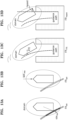
- FIG. 9 is a table illustrating a method of calculating DP points and DP headings according to an embodiment.
- FIG. 10 illustrates examples of DP points and DP headings according to an embodiment of the present disclosure.
- the autonomous navigation controller 1400 may configure a coordinate system with a berthing point at (0,0).
- the berthing point may be determined based on the center point of the ship.
- the left drawing of FIG. 10 shows a berthing method when the berth is on the right
- the right drawing shows a berthing method when the berth is on the left.
- the autonomous navigation controller 1400 determines a berthing start location, that is, a DP point, and a berthing start heading (DP heading), according to the berth location (left/right) and mooring location (PORT/STBD) based on the ship.
- a berthing start location that is, a DP point
- DP heading berthing start heading
- PORT/STBD mooring location
- the DP point when the berth location is (0, 0), if the length of the ship is defined as L and the width as B according to a berthing location and mooring direction, the DP point may be determined as shown in FIG. 9 .
- the autonomous navigation controller 1400 may adjust the coefficients of a to e to match the internal and external conditions of the ship to provide a suitable berthing method according to an entry direction and mooring direction. That is, according to an embodiment of the present disclosure, the berthing start location and heading that enable safe autonomous berthing without invading other berths may be set as shown in FIGS. 9 and 10 .
- FIG. 10 shows an example of berthing of ships 1101 and 1105 entering in the left direction.
- the left drawing shows STBD berthing
- the right drawing shows PORT berthing.
- FIG. 10 shows ships 1102 and 1106 that approaches the DP point and performed dynamic positioning, ships 1003 and 1007 that started the docking phase, and ships 1104 and 1108 that completed the docking phase to be finally berthed.
- the autonomous navigation controller 1400 may determine an initial DP point using the specifications of the ship. For example, the autonomous navigation controller 1400 may set (1 ⁇ a ⁇ 2, 2 ⁇ b ⁇ 3) in (a*L, -b*B) as a value of the initial DP point based on the basic marina design regulations. In addition, the autonomous navigation controller 1400 may determine an initial ship heading value to be a value between 270 degrees and 330 degrees to select the tangent of the guidance path. Meanwhile, in relation to the initial ship heading value, the posture may be determined to match the tangent of the guidance path, but the heading value may also be adjusted not to invade the opposite berth in consideration of a marina situation.
- the autonomous navigation controller 1400 may select a berthing method based on the location and mooring direction of the berth based on a ship entry direction.
- the autonomous navigation controller 1400 may select one of outer side docking and inner side docking.
- the outer side docking is a berthing method of rotating and moving backward at the same time to attach the outer side of the ship to the berth based on the berthing berth
- the inner side docking is a berthing method of rotating sufficiently at the beginning of berthing and then attaching the inner side of the ship based on the berthing berth, while moving backward.
- an error rate with the current state may be first calculated based on DP target coordinates (x dp , y dp ), that is, the DP point, and a target heading angle ⁇ dp , that is, the DP heading.
- control logic using the error rate as a parameter may be executed to generate a control command that control the location and posture of the ship at the DP point.
- a minute error may be corrected by repeatedly performing the process of calculating the error rate and generating the control command described above, and when the error rate decreases below a preset threshold, the location and posture of the ship at the DP point may be determined to be stabilized, and thus, the dynamic positioning phase may terminate and the process may transition to the docking phase.
- the DP point or DP heading may be corrected in the dynamic positioning phase by considering disturbance.
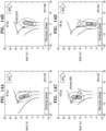
- FIG. 11 illustrates a DP point and DP heading corrected in consideration of disturbance according to an embodiment of the present disclosure.
- the autonomous navigation controller 1400 may calculate a corrected DP point and DP heading that may compensate for or utilize the movement of the ship due to disturbance and determine them as final values. That is, according to the present disclosure, by setting the corrected DP point and DP heading, the movement of the ship due to wind or current may be compensated for in advance.
- FIG. 11 when the wind flows in the right direction, the drawing on the left illustrates a docking phase using an uncorrected DP point, and the drawing on the right illustrates a docking phase using a corrected DP point.
- FIG. 11 sequentially shows ships 1101 and 1104 that started the docking phase at the DP point, ships 1102 and 1105 that moved along the guidance path, and ships 1103 and 1106 in a final berthing state.
- the left drawing which does not consider the wind direction, there is a possibility that the ship 1103 collides with the berth, whereas in the right drawing, because the ship departs from the corrected DP point, the docking process is performed stably and the ship 1106 is berthed.
- the autonomous navigation controller 1400 may compensate for the DP point, which is a start point of the docking phase, in the opposite direction to the direction in which disturbance acts.
- the degree of compensation may be derived based on a preset value determined through analysis of control performance indicators (a state error, such as a heading angle error or a cross track error (XTE)) in a simulation.
- a state error such as a heading angle error or a cross track error (XTE)
- the autonomous navigation controller 1400 may calculate a docking SR in real time during the docking phase.
- the docking SR is a value calculated to prevent the ship from moving away from the guidance path due to disturbance, such as gusts of wind, and being placed in a dangerous situation.
- FIG. 12 is a diagram illustrating a docking SR according to an embodiment.
- FIG. 13 is a diagram illustrating elements for calculating a docking failure rate according to an embodiment of the present disclosure.
- a safety envelope (the solid line) is secondary curves apart by a certain distance from both sides of the guidance path (the dashed line).
- the domain is a virtual domain in an elliptical shape around the ship.
- the thin line along which the center line of the ship moves may be a line indicating an actual movement path.
- the size and shape of the safety envelope and domain may be determined by the length and width of the ship.
- the domain may be a virtual bumper used when calculating a risk of the ship while berthing and may be set in an elliptical shape to simulate the shape of the ship.
- Parameters that determine the elliptical shape of the domain may include a major axis and a minor axis. The major axis may be determined based on an overall length of the ship, and the minor axis may be determined based on a width direction of the ship.
- the major axis of the domain ellipse may be determined by a distance (rest length) over which the ship moves, starting from a control start time to time at which the speed reaches a preset value (e.g., 0.1 m/s), in the case of controlling the engine for the ship to stop at the maximum berthing speed (a reverse speed).
- a preset value e.g. 0. m/s
- the maximum berthing speed refers to the maximum value among preset target reverse speeds.
- the minor axis of the domain ellipse may be determined by a distance over which the ship moves, starting from a control start time to time at which the speed reaches a preset value (e.g., 0.1 m/s), when the ship controls the engine to output the maximum power to the port, while navigating with the maximum power to the starboard using a joystick.
- a preset value e.g. 0. m/s
- the major axis and minor axis of the domain ellipse may be expressed as a function according to the length (L, B) and rest distance of the ship to consider the fact that the major axis and minor axis vary depending on specifications, such as the size of the ship.
- the major axis and minor axis of the domain ellipse may be adjusted through a test run performed by an operator if there is a need to tune the coefficients according to engine performance.
- the autonomous navigation controller 1400 may calculate a docking failure rate (FR), which is the opposite concept to the docking SR.
- FR docking failure rate
- FRdist in (a) of FIG. 13 is a relative distance (obs dist ) risk with respect to a safety envelope invading an elliptical domain.
- FRspd in (b) of FIG. 13 is a relative speed (spd ship ) risk with respect to the safety envelope invading the elliptical domain.
- FR XTE in (c) of FIG. 13 is a risk for a distance (XTE, cross track error) over which the ship deviates from the guidance path.
- FRhazard in (d) of FIG. 13 is a risk for a distance (hazard) over which the stern of the ship deviates based on the berth located in a mooring direction.
- the autonomous navigation controller 1400 may calculate a final risk (FRtotal) having a value of 0 to 1 based on one or more risks among FRdist, FRspd, FRxte, and FRhazard described above and then calculate a final success rate (1- FRtotal).
- FRtotal final risk having a value of 0 to 1 based on one or more risks among FRdist, FRspd, FRxte, and FRhazard described above and then calculate a final success rate (1- FRtotal).
- the autonomous navigation controller 1400 may set a point, as a recovery point, at which collision with the berth may be avoided and the influence of disturbance during subsequent docking may be minimized.
- a point such as a location (x ship ,y ship ) of the ship, a wind direction, and a wind speed immediately after entering the recovery phase may be considered.
- the wind direction may be from left to right.
- the ship may deviate from the guidance path and invade the safety envelope (the solid line), and in this case, the phase of the autonomous berthing mode of the ship may transition from the docking phase to the recovery phase.
- a recovery point when the location of the ship immediately after entering the recovery phase is (x ship ,y ship ), a recovery point may be (x ship + x shift ,y ship + y shift ) and a recovery posture may be heading shift .
- the items x shift , y shift , and heding shift may be determined to set the recovery point and posture. Because x shift is often placed in a dangerous situation as it approaches the berth when the ship is berthed, the recovery point may be set a certain distance (x shift ) ahead of the x ship to reduce the possibility of collision with the berth. In an embodiment, in order to ensure that the ship is sufficiently away from the berth, x shift may be determined as a value by which the ship moves by the minimum distance over which the safety envelope does not overlap the berth.
- the distance (y shift ) to be moved based on the center point of the berth may be set depending on the wind direction and speed and the location to be recovered in a y direction.
- heading shift determines the posture of the ship during recovery and is related to an angle at which the posture of the ship is tilted further depending on the wind direction and wind speed based on a berth entrance direction.
- y shift and heading shift may be determined as values that best follow the guidance path (i.e., that have the best control performance) when an analysis simulation of control performance (XTE, heading error, etc.) is performed by varying wind direction and speed.
- y shift may be determined as a value by which the ship moves by the minimum distance over which the domain does not overlap the berth.
- the autonomous navigation controller 1400 may use values determined in advance through analysis of a control performance indicator through simulation.
- a state error value such as a heading angle error and XTE, etc. may be used.
- the location of the ship may be adjusted to the recovery point by using a fine adjuster, such as a joystick.
- a fine adjuster such as a joystick.
- FIG. 15 is a block diagram illustrating in detail a control apparatus for automatically berthing or unberthing a ship according to an embodiment of the present disclosure.
- FIG. 15 shows the control apparatus 1000 for berthing in FIG. 1 in more detail.
- the sensor 1200 may include a camera sensor 110, a LiDAR sensor 111, and a GPS sensor 112
- the I/O device 1300 may include a monitor 130, a mobile device 150, and a joystick 151
- the autonomous navigation controller 1400 may include an autonomous navigation controller 140
- the ship steering device 1500 may include a throttle/steering 180.
- the classification of each block in FIGS. 1 and 15 is a conceptual classification to easily describe the present disclosure, and the interpretation of embodiments of the present disclosure is not limited to the division of blocks.
- control apparatus 100 for unberthing or berthing a ship may include a plurality of sensors installed in the ship to input various information, for example, the camera sensor 110, the LiDAR sensor 111, the GPS sensor 112, etc.
- the camera sensor 110 may be an individual camera or multiple cameras, through which surround view monitoring (SVM) images around the ship may be implemented.
- SVM surround view monitoring
- the LiDAR sensor 111 is a sensor for light detection and ranging and may measure a distance to a certain object (for example, an obstacle, etc.) around the ship.
- the GPS sensor 112 may provide information on the location of the ship.
- the ship control apparatus 100 for unberthing or berthing a ship also includes an input interface (I/F) module 120, a monitor 130, an autonomous navigation controller 1400, a mobile device 150, and a joystick 151.
- the input I/F module 120 receives image, distance, and location information from the camera sensor 110, the LiDAR sensor 111, and the GPS sensor 112, integrates the information, and displays the integrated sensing information on the monitor 130.
- the monitor 130 may be provided in a cockpit of the ship and may monitor autonomous navigation information (e.g., 3D information, SVM information, etc.) including the integrated sensing information.
- the input I/F module 120 may also provide the integrated sensing information to the autonomous navigation controller 1400, and the autonomous navigation controller 1400 may receive a control command of the driver through the mobile device 150 and the joystick 151.
- the mobile device 150 may communicate with the autonomous navigation controller 1400 wirelessly and may include a smartphone, a tablet computer, etc.
- the joystick 151 may be equipment generally mounted on the cockpit of the ship, and the driver may transmit a control command for driver intervention through the joystick 151 or the mobile device 150.
- the mobile device 150 may remotely monitor the autonomous navigation information, receive berthing conditions, such as a berth location and berthing method, and transmit the received berthing conditions to the autonomous navigation controller 1400.
- the autonomous navigation controller 1400 may perform unberthing or berthing control of the ship based on the integrated sensing information, input berthing conditions, driver control command, etc.
- the control apparatus 100 for unberthing or berthing a ship may also include a switch 160, an engine I/F module 170, a joystick I/F module 171, and the throttle/steering 180.
- the switch 160 determines a transmission path of control commands during automatic unberthing or berthing control by the autonomous navigation controller 1400 and manual unberthing or berthing control by driver intervention.
- control commands are transmitted to the engine I/F module 170, and during manual unberthing or berthing control, control commands are transmitted to the joystick I/F module 171.
- control commands may be transmitted to the joystick I/F module 171 even during automatic unberthing or berthing control.
- the ship in the dynamic positioning phase or recovery phase, which are described below with reference to FIGS. 7 and 8 , the ship is controlled until the ship is stabilized, and here, a control command for stabilizing the ship may be transmitted to the joystick I/F module 171. That is, the autonomous navigation controller 1400 of the present disclosure may adjust the location and posture of the ship by generating a joystick control value and transmitting the joystick control value to the joystick interface module, even if it is not necessarily manual unberthing or berthing control.
- the switch 160 is displayed separately to emphasize a switching function, but in another embodiment, the switching function may be performed by the autonomous navigation controller 1400, and in this case, the switch 160 may be included in the autonomous navigation controller 1400.
- the engine I/F module 170 may control the throttle/steering 180 by outputting a throttle/steering 180 control value to the throttle/steering 180 according to a control command from the autonomous navigation controller 1400 during automatic unberthing or berthing control.
- the joystick I/F module 171 may control the throttle/steering 180 by outputting a corresponding or mapped throttle/steering 180 control value to the throttle/steering 180 according to a control command from the joystick 151 during manual unberthing or berthing control.
- a throttle/steering command transmitted to the engine IF module 170 and a joystick command transmitted to the joystick IF module 171 may be selected depending on the situation.
- the joystick command is transmitted to the joystick IF module 171
- the joystick IF module 171 may transmit the corresponding or mapped throttle and steering values according to the joystick command, and control is performed.
- FIG. 16 shows a computing device 1100 according to an embodiment.
- the computing device 1100 of FIG. 16 may include a communication unit 1110, a processor 1120, and a DB 1130.
- the processor 1120 may physically or conceptually include the autonomous navigation controller 1400
- the DB 1130 may include data provided to the autonomous navigation controller 1400.
- only components related to an embodiment are shown in the computing device 1100 of FIG. 15 . Accordingly, those skilled in the art may understand that other general-purpose components may be included in addition to the components shown in FIG. 15 .
- the communication unit 1110 may include one or more components that enable wired/wireless communication with other nodes.
- the communication unit 1110 may include at least one of a short-range communication unit (not shown), a mobile communication unit (not shown), and a broadcast receiver (not shown).
- the DB 1130 may be hardware that stores various data processed within the computing device 1100 and may store programs for processing and controlling the processor 1120.
- the DB 1130 may store ship information, camera installation information, etc.
- the DB 1130 may include a random access memory (RAM), such as dynamic random access memory (DRAM), static random access memory (SRAM), read-only memory (ROM), electrically erasable programmable read-only memory (EEPROM), CD-ROM, Blu-ray or other optical disk storages, a hard disk drive (HDD), a solid state drive (SSD), or flash memory.
- RAM random access memory
- the processor 1120 controls the overall operation of the computing device 1100.
- the processor 1120 may generally control an input unit (not shown), a display (not shown), the communication unit 1110, the DB 1130, etc. by executing programs stored in the DB 1130.
- the processor 1120 may control the operation of the computing device 1100 by executing programs stored in the DB 1130.
- the processor 1120 may be implemented using at least one of application specific integrated circuits (ASICs), digital signal processors (DSPs), digital signal processing devices (DSPDs), programmable logic devices (PLDs), field programmable gate arrays (FPGAs), controllers, microcontrollers, micro-controllers, microprocessors, and other electrical units for performing functions.
- ASICs application specific integrated circuits
- DSPs digital signal processors
- DSPDs digital signal processing devices
- PLDs programmable logic devices
- FPGAs field programmable gate arrays
- controllers microcontrollers, micro-controllers, microprocessors, and other electrical units for performing functions.
- the embodiments according to the present disclosure may be implemented in the form of a computer program that may be executed through various components on a computer, and such a computer program may be recorded on a computer-readable medium.
- the medium may include magnetic mediums, such as hard disks, floppy disks, and magnetic tapes, optical recording mediums, such as CD-ROMs and DVDs, magneto-optical mediums, such as floptical disks, and hardware devices specifically configured to store and execute program instructions, such as ROM., RAM, flash memory, etc.
- the computer program may be designed and constructed specifically for the present disclosure or may be known and available to those skilled in the art of computer software.
- Examples of computer programs may include not only machine language code, such as that generated by a compiler, but also high-level language code that may be executed by a computer using an interpreter or the like.
- Computer program products are commodities and may be traded between sellers and buyers.
- Computer program products may be distributed in the form of a machine-readable storage medium (e.g. compact disc read only memory (CD-ROM)) or distributed (downloaded or uploaded) online through an application store (e.g. Play Store TM ) or between two user devices.
- a machine-readable storage medium e.g. compact disc read only memory (CD-ROM)
- an application store e.g. Play Store TM
- at least a portion of the computer program product may be at least temporarily stored or temporarily generated in a machine-readable storage medium, such as a server of a manufacturer, a server of an application store, or a memory of a relay server.
Landscapes
- Engineering & Computer Science (AREA)
- Ocean & Marine Engineering (AREA)
- Combustion & Propulsion (AREA)
- Mechanical Engineering (AREA)
- Chemical & Material Sciences (AREA)
- Radar, Positioning & Navigation (AREA)
- Remote Sensing (AREA)
- Physics & Mathematics (AREA)
- General Physics & Mathematics (AREA)
- Automation & Control Theory (AREA)
- Aviation & Aerospace Engineering (AREA)
- Public Health (AREA)
- Health & Medical Sciences (AREA)
- Control Of Position, Course, Altitude, Or Attitude Of Moving Bodies (AREA)
- Navigation (AREA)
Applications Claiming Priority (2)
| Application Number | Priority Date | Filing Date | Title |
|---|---|---|---|
| KR20220190736 | 2022-12-30 | ||
| PCT/KR2023/022040 WO2024144370A1 (fr) | 2022-12-30 | 2023-12-29 | Procédé et appareil de commande de l'amarrage ou du désamarrage automatique d'un navire |
Publications (2)
| Publication Number | Publication Date |
|---|---|
| EP4520649A1 true EP4520649A1 (fr) | 2025-03-12 |
| EP4520649A4 EP4520649A4 (fr) | 2025-10-15 |
Family
ID=91718489
Family Applications (1)
| Application Number | Title | Priority Date | Filing Date |
|---|---|---|---|
| EP23913044.6A Pending EP4520649A4 (fr) | 2022-12-30 | 2023-12-29 | Procédé et appareil de commande de l'amarrage ou du désamarrage automatique d'un navire |
Country Status (4)
| Country | Link |
|---|---|
| US (1) | US20250128806A1 (fr) |
| EP (1) | EP4520649A4 (fr) |
| KR (2) | KR102781362B1 (fr) |
| WO (1) | WO2024144370A1 (fr) |
Families Citing this family (4)
| Publication number | Priority date | Publication date | Assignee | Title |
|---|---|---|---|---|
| WO2026034864A1 (fr) * | 2024-08-07 | 2026-02-12 | 주식회사 아비커스 | Procédé et dispositif de calcul de position pour commander le mouvement d'un navire |
| WO2026034968A1 (fr) * | 2024-08-07 | 2026-02-12 | 주식회사 아비커스 | Procédé et appareil de commande de position de navire |
| WO2026034860A1 (fr) * | 2024-08-07 | 2026-02-12 | 주식회사 아비커스 | Procédé et appareil de commande d'accostage autonome de navire |
| CN119611645B (zh) * | 2025-02-14 | 2025-04-18 | 中国海洋大学 | 一种采样船投放及回收装置及其控制方法 |
Family Cites Families (8)
| Publication number | Priority date | Publication date | Assignee | Title |
|---|---|---|---|---|
| KR101620369B1 (ko) * | 2016-02-01 | 2016-05-13 | 주식회사 마텍 | 선박 접안 관리 시스템 및 이의 실행 방법 |
| JP6969047B2 (ja) * | 2018-03-20 | 2021-11-24 | 三井E&S造船株式会社 | 船舶の自動操船システム |
| KR20190122978A (ko) * | 2018-04-23 | 2019-10-31 | 주식회사 에이피에스 | 스러스트 적용 선박의 운전자 편의성 제공을 위한 접이안 보조 제어시스템 |
| CA3101609C (fr) * | 2018-06-01 | 2023-10-10 | Wartsila Sam Electronics Gmbh | Procede, dispositif et appareil de commande d'entree au bassin autonome de navire marin |
| JP7083081B2 (ja) * | 2018-10-10 | 2022-06-10 | ヤンマーパワーテクノロジー株式会社 | 自動着岸装置 |
| KR102223363B1 (ko) * | 2020-06-16 | 2021-03-05 | 이상창 | 선박 자동정박 시스템 |
| US12066827B2 (en) * | 2021-03-09 | 2024-08-20 | Yamaha Hatsudoki Kabushiki Kaisha | Watercraft auto-docking system and watercraft auto-docking method |
| KR102617988B1 (ko) * | 2021-03-24 | 2023-12-29 | 주식회사 비지에스 | 어라운드 뷰를 이용한 자율운항선박의 접이안 시스템 |
-
2023
- 2023-12-29 EP EP23913044.6A patent/EP4520649A4/fr active Pending
- 2023-12-29 WO PCT/KR2023/022040 patent/WO2024144370A1/fr not_active Ceased
- 2023-12-29 KR KR1020230196564A patent/KR102781362B1/ko active Active
-
2024
- 2024-12-19 US US18/987,372 patent/US20250128806A1/en active Pending
-
2025
- 2025-03-10 KR KR1020250030656A patent/KR20250037740A/ko active Pending
Also Published As
| Publication number | Publication date |
|---|---|
| US20250128806A1 (en) | 2025-04-24 |
| KR102781362B1 (ko) | 2025-03-17 |
| EP4520649A4 (fr) | 2025-10-15 |
| KR20240108295A (ko) | 2024-07-09 |
| KR20250037740A (ko) | 2025-03-18 |
| WO2024144370A1 (fr) | 2024-07-04 |
Similar Documents
| Publication | Publication Date | Title |
|---|---|---|
| EP4520649A1 (fr) | Procédé et appareil de commande de l'amarrage ou du désamarrage automatique d'un navire | |
| US12165522B1 (en) | Marine propulsion control system and method with collision avoidance override | |
| US12371140B1 (en) | Marine propulsion control system, method, and user interface for marine vessel docking and launch | |
| US11600184B2 (en) | Marine propulsion control system and method | |
| US12077266B2 (en) | Navigation scene analysis systems and methods | |
| US11862026B2 (en) | Marine propulsion control system and method with proximity-based velocity limiting | |
| US10037701B2 (en) | Watercraft navigation safety system | |
| KR101764600B1 (ko) | 무인항공기 기반의 선박 항해 방법 및 시스템 | |
| JP7622024B2 (ja) | 多重映像ベースの船舶近接周辺状況認識支援システム及び方法 | |
| KR20210123131A (ko) | 선박의 충돌 회피방법 | |
| KR20220132910A (ko) | 자율운항선박의 충돌회피 시스템 | |
| RU2501708C1 (ru) | Способ автоматической проводки судна | |
| EP4521066A1 (fr) | Dispositif et procédé de calcul de risque de collision de navire | |
| EP3538845B1 (fr) | Procédé de prise en charge de la manoeuvre d'approche d'un bateau sur le site d'amarrage dans une zone de port et système associé | |
| US12454341B1 (en) | Marine propulsion control system, method, and user interface | |
| KR102930217B1 (ko) | 선박을 자동으로 접안하는 방법 및 장치 | |
| US12298769B1 (en) | Navigation control system and method for a marine vessel | |
| US12503207B1 (en) | Marine propulsion control system and method with proximity-based velocity limiting | |
| US12545376B1 (en) | Marine navigation systems, methods, and user interfaces | |
| US12559212B1 (en) | System and method for controlling docking for a marine vessel | |
| US12457420B1 (en) | Systems and methods for adjusting a field of view of a vision system on a marine vessel | |
| KR20260022219A (ko) | 선박의 움직임을 제어하기 위한 위치를 산출하는 방법 및 장치 |
Legal Events
| Date | Code | Title | Description |
|---|---|---|---|
| STAA | Information on the status of an ep patent application or granted ep patent |
Free format text: STATUS: THE INTERNATIONAL PUBLICATION HAS BEEN MADE |
|
| PUAI | Public reference made under article 153(3) epc to a published international application that has entered the european phase |
Free format text: ORIGINAL CODE: 0009012 |
|
| STAA | Information on the status of an ep patent application or granted ep patent |
Free format text: STATUS: REQUEST FOR EXAMINATION WAS MADE |
|
| 17P | Request for examination filed |
Effective date: 20241204 |
|
| AK | Designated contracting states |
Kind code of ref document: A1 Designated state(s): AL AT BE BG CH CY CZ DE DK EE ES FI FR GB GR HR HU IE IS IT LI LT LU LV MC ME MK MT NL NO PL PT RO RS SE SI SK SM TR |
|
| A4 | Supplementary search report drawn up and despatched |
Effective date: 20250912 |
|
| RIC1 | Information provided on ipc code assigned before grant |
Ipc: B63B 79/40 20200101AFI20250908BHEP Ipc: B63B 79/10 20200101ALI20250908BHEP Ipc: B63B 43/20 20060101ALI20250908BHEP Ipc: B63H 21/21 20060101ALI20250908BHEP Ipc: B63H 21/22 20060101ALI20250908BHEP Ipc: B63B 49/00 20060101ALI20250908BHEP Ipc: G05D 1/606 20240101ALI20250908BHEP Ipc: G05D 1/661 20240101ALI20250908BHEP Ipc: G05D 107/80 20240101ALI20250908BHEP Ipc: G05D 109/30 20240101ALI20250908BHEP |
|
| DAV | Request for validation of the european patent (deleted) | ||
| DAX | Request for extension of the european patent (deleted) |