EP4520653A1 - Mécanisme de poignée de porte de passager d'aéronef - Google Patents
Mécanisme de poignée de porte de passager d'aéronef Download PDFInfo
- Publication number
- EP4520653A1 EP4520653A1 EP24180179.4A EP24180179A EP4520653A1 EP 4520653 A1 EP4520653 A1 EP 4520653A1 EP 24180179 A EP24180179 A EP 24180179A EP 4520653 A1 EP4520653 A1 EP 4520653A1
- Authority
- EP
- European Patent Office
- Prior art keywords
- door
- aircraft passenger
- lock
- passenger door
- vent
- Prior art date
- Legal status (The legal status is an assumption and is not a legal conclusion. Google has not performed a legal analysis and makes no representation as to the accuracy of the status listed.)
- Pending
Links
Images


Classifications
-
- B—PERFORMING OPERATIONS; TRANSPORTING
- B64—AIRCRAFT; AVIATION; COSMONAUTICS
- B64C—AEROPLANES; HELICOPTERS
- B64C1/00—Fuselages; Constructional features common to fuselages, wings, stabilising surfaces or the like
- B64C1/14—Windows; Doors; Hatch covers or access panels; Surrounding frame structures; Canopies; Windscreens accessories therefor, e.g. pressure sensors, water deflectors, hinges, seals, handles, latches, windscreen wipers
- B64C1/1407—Doors; surrounding frames
- B64C1/1423—Passenger doors
- B64C1/143—Passenger doors of the plug type
-
- B—PERFORMING OPERATIONS; TRANSPORTING
- B64—AIRCRAFT; AVIATION; COSMONAUTICS
- B64C—AEROPLANES; HELICOPTERS
- B64C1/00—Fuselages; Constructional features common to fuselages, wings, stabilising surfaces or the like
- B64C1/14—Windows; Doors; Hatch covers or access panels; Surrounding frame structures; Canopies; Windscreens accessories therefor, e.g. pressure sensors, water deflectors, hinges, seals, handles, latches, windscreen wipers
- B64C1/1407—Doors; surrounding frames
- B64C1/1423—Passenger doors
-
- B—PERFORMING OPERATIONS; TRANSPORTING
- B64—AIRCRAFT; AVIATION; COSMONAUTICS
- B64C—AEROPLANES; HELICOPTERS
- B64C1/00—Fuselages; Constructional features common to fuselages, wings, stabilising surfaces or the like
- B64C1/14—Windows; Doors; Hatch covers or access panels; Surrounding frame structures; Canopies; Windscreens accessories therefor, e.g. pressure sensors, water deflectors, hinges, seals, handles, latches, windscreen wipers
- B64C1/1407—Doors; surrounding frames
Definitions
- the present disclosure generally relates to aircraft passenger door handle mechanisms. More particularly, the present disclosure relates to lift to open aircraft passenger door handle mechanisms.
- Aircraft passenger door handle mechanisms may typically have a rotate to open handle motion or a lift to open handle motion. Such a rotate to open handle motion configurations typically requires a complicated series of linkages and cams to achieve the required actions to vent cabin pressure, unlock, and then unlatch the door. Conversely, lift to open handle motion configurations may not typically have mechanisms associated with rotate to open handle motion configurations.
- lift to open handle motion configurations may not typically have mechanisms associated with rotate to open handle motion configurations.
- lift to open handle configurations may often not include a means to vent pressure or prevent opening while pressurized local to the door.
- a door handle mechanism including a vent panel, a handle lever, and a four bar mechanism.
- the handle lever has a lift-to-open configuration.
- the four bar mechanism is coupled to the handle lever and the vent panel.
- the four bar mechanism is to time sequence operations to close an aircraft passenger door, latch the aircraft passenger door, lock the aircraft passenger door, and close the vent panel in response to the handle lever being toggled between a closed position and an open position.
- some examples herein present a simple handle mechanism that contains mechanical features to prevent opening the door while the cabin is pressurized. This mechanism is lighter, less expensive, and less complicated than the mechanisms that provide the same functionality in some existing aircraft. Additionally, or alternatively, some implementations herein present a passenger door handle mechanism that includes a lock, features to operate a vent panel, and features to prevent back driving the mechanism, which prevent unintended opening.
- such a handle mechanism uses a "lift to open” motion to open rather than a “rotate to open” motion. This allows a more compact installation and allows the mechanism to be located aft of the door hinge, rather than under the door hinge.
- such a handle mechanism uses a 4 bar mechanism with a floating link (e.g., a mechanism operator). Accordingly, the mechanism operator (one bar of the 4 bar mechanism) does not rotate around a fixed point. The mechanism operator controls the position of an upper link (another bar of the 4 bar mechanism) and a lower link (a further bar of the 4 bar mechanism).
- the lower link includes three locking features to ensure the door cannot open unless certain conditions are met necessary for safety. Because the handle mechanism operator does not rotate around a fixed point, and because its closed position is over-center with respect to a latch rod, application of back driving loads to the latch rod cannot unlatch the door.
- a handle can be integrated with the mechanism operator reducing the number of joints and rotation points.
- a door handle mechanism includes a vent panel, a handle lever, and a four bar mechanism.
- the handle lever has a lift-to-open configuration.
- the four bar mechanism is coupled to the handle lever and the vent panel.
- the four bar mechanism is to time sequence operations to close an aircraft passenger door, latch the aircraft passenger door, lock the aircraft passenger door, and close the vent panel in response to the handle lever being toggled between a closed position and an open position.
- an aircraft passenger door in another example, includes a door main body and a door handle mechanism coupled to the door main body.
- the door handle mechanism includes a vent panel, a handle lever, and a four bar mechanism.
- the handle lever has a lift-to-open configuration.
- the four bar mechanism is coupled to the handle lever and the vent panel. The four bar mechanism is to time sequence operations to close an aircraft passenger door, latch the aircraft passenger door, lock the aircraft passenger door, and close the vent panel in response to the handle lever being toggled between a closed position and an open position.
- a method in a further example, includes toggling a handle lever between a closed position and an open position, where the handle lever has a lift-to-open configuration.
- the method further includes timing sequencing of operations to close an aircraft passenger door, latch the aircraft passenger door, lock the aircraft passenger door, and close a vent panel in response to the handle lever being toggled between the closed position and the open position.
- the timing of the sequencing of operations is performed via a four bar mechanism coupled to the handle lever and the vent panel.
- FIG. 1 is an illustration of an aircraft 100 with an aircraft passenger door 102 according to an example.
- the aircraft 100 includes an aircraft fuselage having one or more aircraft passenger door 102 located therein.
- FIG. 2 is an illustration of an aircraft passenger door 102 according to an example.
- aircraft passenger door 102 includes a hinge 202 coupled to a door main body 201.
- the hinge 202 is located at an outer rim of the door main body 201.
- a door handle mechanism 300 is coupled to the door main body 201 and is located at a spaced lateral position with respect to the hinge 202. Additional details regarding the door handle mechanism 300 will be discussed below with regard to FIGS. 3-13 .
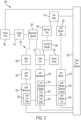
- FIG. 3 is a schematic view illustrating a door handle mechanism 300 of an aircraft passenger door according to an example.
- the door handle mechanism 300 includes a vent panel 312, a handle lever 304, and a four bar mechanism 305 coupled to the handle lever 304 and the vent panel 312.
- the four bar mechanism 305 is to time sequence operations to close the aircraft passenger door 102 (see, e.g., FIG. 2 ), latch the aircraft passenger door 102, lock the aircraft passenger door 102, and close the vent panel 312 in response to the handle lever 304 being toggled between a closed position and an open position.
- four bar mechanism refers to a four-bar linkage (e.g., a four bar) of four bodies, called bars or links, connected in a loop by four joints that forms a closed-chain movable linkage mechanism.
- the four bar mechanism 305 includes mechanism operator 306, upper link 308, lower link 310 and fixed door structure 302.
- the handle lever 304 is a separate part from each bar of the four bar mechanism 305.
- the mechanism operator 306 is separate from the handle lever 304, and is connected via a handle rod 314.
- the handle lever 304 is incorporated into mechanism operator 306 (e.g., incorporated into one bar of the four bar mechanism 305, as illustrated in FIG. 14 ).
- the mechanism operator 306 (e.g., as one bar of the four bar mechanism 305) is configured to orbit two attached points as a floating link so as to bypass rotation about a fixed point (as illustrated in greater detail below in FIG. 7 ).
- the door handle mechanism 300 further includes a tension spring 360.
- the tension spring 360 is to bias the mechanism operator 306 towards a closed position.
- the four bar mechanism 305 has upper link 308 and lower link 310 (e.g., as two bars of the four bar mechanism 305) that are positioned to cross one another. Such an implementation is illustrated in greater detail below with regard to FIG. 8 .
- the upper link 308 and the lower link 310 e.g., as two bars of the four bar mechanism 305) have lines of action so as to cross one another in operation. More specifically, the upper link 308 has a line of action 808 and the lower link 10 has a line of action 810, where the upper link 308 line of action 808 crosses the lower link 310 line of action 810.
- the door handle mechanism 300 further includes a latch rod 320 and a latch mechanism 322.
- the latch rod 320 is coupled to the four bar mechanism 305 via a latch shaft 1202 (e.g., see FIG. 12 ).
- the latch mechanism 322 is coupled to the latch rod 320.
- the latch shaft 1202 has an over-center position 1204 when the aircraft passenger door 102 (e.g., see FIG. 2 ) is locked.
- the over-center position 1204 is to drive the latch mechanism 322 towards a locking position prior to driving the latch mechanism 322 towards an unlocking position to prevent the latch mechanism 322 from being capable of back-driving a lock mechanism 330.
- the lower link 310 (e.g., as one bar of the four bar mechanism 305) is associated with a lock mechanism 330.
- the lock mechanism 330 includes one or more of the following locking features: a lock sector 334 to lock a latch mechanism 322, a lock blocking feature 336 to prevent opening of the aircraft passenger door 102 when the vent panel 312 is closed, or a lock pawl 338 to prevent closing the vent panel 312 until the aircraft passenger door 102 is locked.
- the lock sector 334 is to lock the latch mechanism 322 via a latch lock finger 324 of the latch mechanism 322.
- the lock mechanism 330 also interacts with a vent monitor 340 to control operation of the vent panel 312.
- the lock blocking feature 336 is to prevent opening of the aircraft passenger door 102 when the vent panel 312 is closed via interaction with a vent monitor blocking feature 346 of vent monitor 340.
- the lock pawl 338 is to prevent closing the vent panel 312 until the aircraft passenger door 102 is locked via interaction with a vent monitor tab 348 of vent monitor 340.
- the lower link 310 activates vent panel 312 via a vent rod operator 350 connected to the vent panel 312 via vent panel rod 352.
- the vent monitor 340 similarly is connected to the vent panel 312 via vent monitor rod 354.
- FIGS. 4-13 Additional details regarding the design and operation of individual elements of door handle mechanism 300 are found below in FIGS. 4-13 .
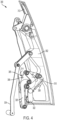
- FIG. 4 is a side view illustrating a door handle mechanism 300 according to an example.
- handle lever 304 is shown in a lift to open arrangement.
- the four bar mechanism 305 may control a handle locking feature and a vent panel monitor feature. Additional details regarding such operations can be found below in the discussion of FIG. 18 .
- the four bar mechanism 305 can be timed to ensure proper sequencing.
- FIG. 5 is a perspective view illustrating a door handle mechanism 300 according to an example.
- latch mechanism 322 rotates in the counter clockwise direction to move from the latched position (illustrated here) to an unlatched position.
- the lock sector 334 of a lock mechanism blocks the latch mechanism 322 from rotation in the counter clockwise direction.
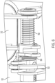
- FIG. 6 is a side view illustrating a biasing mechanism 602 for a vent panel 312 according to an example.
- the biasing mechanism 602 is to bias the vent panel 312 towards an open position.
- the vent panel rod 352 pushes the vent panel closed against the forces of the biasing mechanism 602.
- operator spring 604 holds the vent panel 312 unless the spring force is exceeded ty airplane pressure forces that tend to hold the vent panel 312 closed.
- the vent panel 312 is a small door within the aircraft passenger door 102.
- the vent panel 312 remains open until the aircraft passenger door 102 is locked. This prevents the aircraft from being pressurized if the door is not locked. Similarly, the vent panel 312 is to be opened before the door can become unlocked. This prevents the aircraft passenger door 102 from being opened when the aircraft is pressurized.
- vent panel 312 will remain closed when the cabin is pressurized.
- Mechanisms will keep the aircraft passenger door locked to prevent aircraft passenger door locked from opening when the vent panel 312 is closed.
- the aircraft passenger door is prevented from opening when the cabin is pressurized. This prevents unsafe opening that could injure a door operator.
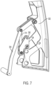
- FIG. 7 is a side view illustrating a mechanism operator of a door handle mechanism according to an example.
- the mechanism operator 306 is separate from the handle lever 304, and is connected via handle rod 314.
- mechanism operator 306 rotates around two shafts. More specifically, the mechanism operator 306 is configured to orbit two attached points as a floating link so as to bypass rotation about a fixed point.
- FIG. 8 is a side view illustrating components of a 4 bar mechanism 305 according to an example.
- the four bar mechanism 305 has upper link 308 and lower link 310 (e.g., as two bars of the four bar mechanism 305) that are positioned to cross one another.
- the upper link 308 and the lower link 310 e.g., as two bars of the four bar mechanism 305) have lines of action so as to cross one another in operation. More specifically, the upper link 308 has a line of action 808 and the lower link 10 has a line of action 810, where the upper link 308 line of action 808 crosses the lower link 310 line of action 810.
- mechanism operator 306 rotates around the lower link 310 on a common shaft.
- mechanism operator 306 rotates around the upper link 308 on another common shaft.
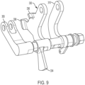
- FIG. 9 is a perspective view illustrating components of a lower link 310 according to an example.
- the lower link 310 operates lock mechanism 330 and vent rod operator 350.
- lock mechanism 330 includes lock sector 334, lock blocking feature 336, and lock pawl 338.
- the lower link e.g., as one bar of the four bar mechanism 305
- the lock mechanism 330 includes one or more of the following locking features: a lock sector 334 to lock a latch mechanism 322, a lock blocking feature 336 to prevent opening of the aircraft passenger door 102 when the vent panel 312 is closed, or a lock pawl 338 to prevent closing the vent panel 312 until the aircraft passenger door 102 is locked.
- the lock sector 334 is to lock the latch mechanism 322 via a latch lock finger 324 of the latch mechanism 322.
- FIG. 10 is a perspective view illustrating components of an upper link 308 according to an example.
- the upper link 308 and vent monitor 340 share a common shaft but rotate independently of one another.
- vent monitor 340 interacts with a vent panel via vent rod operator 350. As illustrated, vent monitor 340 includes a vent monitor blocking feature 346 and a vent monitor tab 348.
- the vent monitor blocking feature 346 and vent monitor tab 348 prevent the lower link 310 from rotating in some conditions.
- the vent monitor blocking feature 346 and vent monitor tab 348 prevent door unlocking when the vent panel 312 is closed and prevent the door from unlocking when the vent is open. Accordingly, the vent monitor blocking feature 346 operates as a vent closed blocking stop, while the vent monitor tab 348 operates as a vent open blocking stop.
- FIGS. 11A-11D illustrates components of a lock mechanism of in operation according to an example.
- the vent panel cannot close until the aircraft passenger door is closed.
- FIG. 11A illustrates that the lock pawl 338 is engaged with the vent monitor tab 348 while latch lock finger 324 is not engaged with the lock sector 334. Accordingly, the lock pawl 338 prevents the vent from closing during a door closing sequence and the door remains unlocked and the vent is open.
- FIG. 11B illustrates that the lock pawl 338 remains engaged with the vent monitor tab 348 while latch lock finger 324 is now engaged with the lock sector 334. Accordingly, the lock pawl 338 prevents the vent from closing during the door closing sequence and the door is now locked and the vent is open.
- FIG. 11C illustrates that the lock pawl 338 is now disengaged from the vent monitor tab 348 while latch lock finger 324 remains engaged with the lock sector 334. Accordingly, the lock pawl 338 no longer prevents the vent from closing during the door closing sequence and the door remains locked and the vent is open.
- FIG. 11D illustrates that after the lock pawl 338 is disengaged from the vent monitor tab 348 and the latch lock finger 324 remains engaged with the lock sector 334 the vent may now close.
- FIG. 12 is a side view illustrating a tension spring 360 of a door handle mechanism according to an example, the door handle mechanism 300 further includes tension spring 360.
- the tension spring 360 is to bias the mechanism operator 306 towards a closed position.
- the door handle mechanism 300 further includes a latch rod 320 and a latch mechanism 322.
- the latch rod 320 is coupled to the four bar mechanism 305 via a latch shaft 1202.
- the latch mechanism 322 is coupled to the latch rod 320.
- the latch shaft 1202 has an over-center position 1204 when the aircraft passenger door 102 (e.g., see FIG. 2 ) is locked.
- the over-center position 1204 is to drive the latch mechanism 322 towards a locking position prior to driving the latch mechanism 322 towards an unlocking position to prevent the latch mechanism 322 from being capable of back-driving a lock mechanism 330 (e.g., see FIG. 9 ).
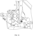
- FIG. 13 illustrates components of a lock mechanism 330 in operation according to an example.
- the lock blocking feature 336 of the lock mechanism 330 engages with the vent monitor blocking feature 346 of the vent monitor 340.
- lock blocking feature 336 In operation, such interaction between the lock blocking feature 336 and the vent monitor blocking feature 346 prevents the lock sector 334 from moving out of the way of latch lock finger 324, ensuring a locked condition.
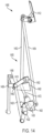
- FIG. 14 is a side view illustrating another door handle mechanism 1400 according to another example.
- the handle lever is incorporated into mechanism operator 1406 (e.g., incorporated into one bar of the four bar mechanism 1405).
- the mechanism operator 1406 (e.g., as one bar of the four bar mechanism 1405) is configured to orbit two attached points as a floating link so as to bypass rotation about a fixed point (similar to the implementation illustrated in greater detail below in FIG. 7 ).
- the door handle mechanism 1400 includes a vent panel 1412 and a four bar mechanism 1405 coupled to the vent panel 1412.
- the four bar mechanism 1405 is to time sequence operations to close the aircraft passenger door 102 (see, e.g., FIG. 2 ), latch the aircraft passenger door 102, lock the aircraft passenger door 102, and close the vent panel 1412 in response to the handle lever incorporated into the mechanism operator 1406 being toggled between a closed position and an open position.
- the four bar mechanism 1405 includes mechanism operator 1406, upper link 1408, lower link 1410 and fixed door structure 1402.
- the four bar mechanism 1405 has upper link 1408 and lower link 1410 (e.g., as two bars of the four bar mechanism 1405) that are positioned to cross one another.
- the door handle mechanism 1400 further includes a latch rod 1420 and a latch mechanism 1422.
- the latch rod 1420 is coupled to the four bar mechanism 1405 via a latch shaft 1482.
- the latch mechanism 1422 is coupled to the latch rod 1420. Similar to the arrangement illustrated in FIG. 12 , the latch shaft 1482 has an over-center position when the aircraft passenger door 102 (e.g., see FIG. 2 ) is locked. The over-center position is to drive the latch mechanism 1422 towards a locking position prior to driving the latch mechanism 1422 towards an unlocking position to prevent the latch mechanism 1422 from being capable of back-driving a lock mechanism 1430.
- the lower link 1410 (e.g., as one bar of the four bar mechanism 1405) is associated with the lock mechanism 1430 via lock rod 1472.
- the lower link 1410 activates vent panel 1412 via vent panel rod 1452.
- the vent panel 1412 is also controlled via vent monitor rod 1454.
- FIG. 15 illustrates components of a door handle mechanism in operation according to another example.
- the handle lever incorporated into mechanism operator 1406 has an elliptical path 1504 when open and closed (as compared to a circular path 1502).
- FIG. 16 is a perspective view illustrating a door handle mechanism of an aircraft passenger door according to another example.
- the lock mechanism 1430 includes a lock sector 1434 to lock a latch mechanism 1422. More specifically, the lock sector 1434 is to lock the latch mechanism 1422 via a latch lock finger 1424 of the latch mechanism 1422.
- FIG. 17 shows an example method 1700 for operating a door handle mechanism for an aircraft according to an example.
- the method 1700 can generally be implemented for operating a door handle mechanism, such as, for example, the operating a door handle mechanism 300 ( FIG. 3 ) and/or the operating a door handle mechanism 1400 ( FIG. 14 ), already discussed.
- Illustrated processing block 1702 provides for toggling a handle lever between a closed position and an open position.
- a handle lever may be toggled between a closed position and an open position, where the handle lever has a lift-to-open configuration.
- Illustrated processing block 1704 provides for timing sequencing of operations in response to the handle lever being toggled between the closed position and the open position. For example, a sequencing of operations may be timed to close an aircraft passenger door, latch the aircraft passenger door, lock the aircraft passenger door, and close a vent panel in response to the handle lever being toggled between the closed position and the open position. In some implementations, the timing of the sequencing of operations is performed via a four bar mechanism coupled to the handle lever and the vent panel.
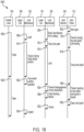
- FIG. 18 is a flowchart of an example of another method 1800 for operating a door handle mechanism for an aircraft according to an example.
- the method 1800 can generally be implemented for operating a door handle mechanism, such as, for example, the operating a door handle mechanism 300 ( FIG. 3 ) and/or the operating a door handle mechanism 1400 ( FIG. 14 ), already discussed.
- Illustrated processing block 1802 provides for the process starting with a vent open.
- a vent panel may be in an open position prior to beginning closing of an aircraft passenger door.
- Illustrated processing blocks 1804-1818 may occur a closing of the aircraft passenger door at illustrated processing block 1806.
- Illustrated processing block 1804 provides for blocking a vent monitor from rotating.
- a vent monitor may be blocked from rotating via a lock pawl of a locking mechanism engaging the vent monitor.
- Illustrated processing block 1808 provides for latching the aircraft passenger door.
- the aircraft passenger door may be latched via a latch mechanism.
- Illustrated processing block 1810 provides for preventing closing the vent panel until locking. For example, closing the vent panel is prevented until the aircraft passenger door is locked in response to the lock pawl engaging the vent monitor.
- Illustrated processing block 1812 provides for clearing the lock pawl.
- the lock pawl may be cleared from the vent monitor.
- Illustrated processing block 1814 provides for a tension spring holding the closed position.
- Illustrated processing block 1816 provides for locking the aircraft passenger door .
- the aircraft passenger door may be locked via the locking mechanism.
- Illustrated processing block 1818 provides for closing the vent panel.
- the vent panel may be closed at the end of closing of the handle lever.
- Illustrated processing blocks 1822-1834 may occur an opening of the aircraft passenger door at illustrated processing block 1820.
- Illustrated processing block 1822 provides for over-center position operations.
- the latch mechanism may be driven towards a locking position prior to driving the latch mechanism towards an unlocking position to prevent the latch mechanism from being capable of back-driving the lock mechanism based on such an over-center position.
- Illustrated processing block 1824 provides for preventing disengagement of lock mechanism.
- disengagement of the lock mechanism may be prevented via a lock blocking feature of the locking mechanism engaging the vent monitor.
- Illustrated processing block 1826 provides for preventing opening of the aircraft passenger door when the vent panel is closed. For example, preventing opening of the aircraft passenger door may be prevented when the vent panel is closed in response to the lock blocking feature engaging the vent monitor.
- Illustrated processing block 1830 provides for opening the vent panel.
- Illustrated processing block 1832 provides for unlocking the aircraft passenger door.
- the aircraft passenger door may be unlocked via the locking mechanism.
- Illustrated processing block 1834 provides for unlatching the aircraft passenger door.
- the aircraft passenger door may be unlatched via the latch mechanism.
- An aircraft passenger door including: a door main body; and a door handle mechanism coupled to the door main body.
- the door handle mechanism includes: a vent panel; a handle lever having a lift-to-open configuration; and a four bar mechanism coupled to the handle lever and the vent panel.
- the four bar mechanism is to time sequence operations to close the aircraft passenger door, latch the aircraft passenger door, lock the aircraft passenger door, and close the vent panel in response to the handle lever being toggled between a closed position and an open position.
- Clause 2 The aircraft passenger door of clause 1, further including: a hinge coupled to the door main body and located at an outer rim of the door main body; where the door handle mechanism is located at a spaced lateral position with respect to the hinge.
- Clause 3 The aircraft passenger door of any one of Clauses 1 to 2, where the handle lever is incorporated into one bar of the four bar mechanism.
- Clause 4 The aircraft passenger door of any one of Clauses 1 to 2, where the handle lever is a separate part from each bar of the four bar mechanism.
- Clause 5 The aircraft passenger door of Clause 4, where one bar of the four bar mechanism includes a mechanism operator configured to orbit two attached points as a floating link so as to bypass rotation about a fixed point.
- the door handle mechanism further including: a tension spring to bias the mechanism operator towards a closed position.
- the door handle mechanism further including: a latch rod coupled to the four bar mechanism via a latch shaft; and a latch mechanism coupled to the latch rod; where the latch shaft has an over-center position when the aircraft passenger door is locked, where the over-center position is to drive the latch mechanism towards a locking position prior to driving the latch mechanism towards an unlocking position to prevent the latch mechanism from being capable of back-driving a lock mechanism.
- Clause 8 The aircraft passenger door of any one of Clauses 1 to 7, where the four bar mechanism has two bars of the four bar mechanism that are positioned to cross one another.
- Clause 9 The aircraft passenger door of any one of Clauses 1 to 8, where the four bar mechanism has one bar of the four bar mechanism that includes one or more of the following locking features: a lock sector to lock a latch mechanism, a lock blocking feature to prevent opening of the aircraft passenger door when the vent panel is closed, or a lock pawl to prevent closing the vent panel until the aircraft passenger door is locked.
- Clause 10 The aircraft passenger door of any one of Clauses 1 to 9, the door handle mechanism further including: a biasing mechanism to bias the vent panel towards a closed position.
- a door handle mechanism including: a vent panel; a handle lever having a lift-to-open configuration; and a four bar mechanism coupled to the handle lever and the vent panel.
- the four bar mechanism is to time sequence operations to close an aircraft passenger door, latch the aircraft passenger door, lock the aircraft passenger door, and close the vent panel in response to the handle lever being toggled between a closed position and an open position.
- Clause 16 The door handle mechanism of any one of Clauses 11 to 15, where the four bar mechanism has two bars of the four bar mechanism that are positioned to cross one another.
- Clause 17 The door handle mechanism of any one of Clauses 11 to 16, where the four bar mechanism has one bar of the four bar mechanism that includes one or more of the following locking features: a lock sector to lock a latch mechanism, a lock blocking feature to prevent opening of the aircraft passenger door when the vent panel is closed, or a lock pawl to prevent closing the vent panel until the aircraft passenger door is locked.
- Clause 18 The door handle mechanism of any one of Clauses 11 to 17, the door handle mechanism further including: a biasing mechanism to bias the vent panel towards a closed position.
- a method including: toggling a handle lever between a closed position and an open position, where the handle lever has a lift-to-open configuration; and timing sequencing of operations to close an aircraft passenger door, latch the aircraft passenger door, lock the aircraft passenger door, and close a vent panel in response to the handle lever being toggled between the closed position and the open position, and where the timing of the sequencing of operations is performed via a four bar mechanism coupled to the handle lever and the vent panel.
- Clause 20 The method of Clause 19, further including: during a closing of the aircraft passenger door: latching the aircraft passenger door via a latch mechanism; blocking a vent monitor from rotating via a lock pawl of a locking mechanism engaging the vent monitor; preventing closing the vent panel until the aircraft passenger door is locked in response to the lock pawl engaging the vent monitor; clearing the lock pawl from the vent monitor; locking the aircraft passenger door via the locking mechanism; and closing the vent panel; during an opening of the aircraft passenger door: driving the latch mechanism towards a locking position prior to driving the latch mechanism towards an unlocking position to prevent the latch mechanism from being capable of back-driving the lock mechanism; preventing disengagement of the lock mechanism via a lock blocking feature of the locking mechanism engaging the vent monitor; preventing opening of the aircraft passenger door when the vent panel is closed in response to the lock blocking feature engaging the vent monitor; clearing the lock blocking feature from the vent monitor; opening the vent panel; unlocking the aircraft passenger door via the locking mechanism; and unlatching the aircraft passenger door via the latch mechanism
- Clause 21 includes an apparatus comprising means for performing the function of any preceding example.
- Coupled can be used herein to refer to any type of relationship, direct or indirect, between the components in question, and can apply to electrical, mechanical, fluid, optical, electromagnetic, electro-mechanical or other connections. Additionally, the terms “first,” “second,” etc. are used herein only to facilitate discussion, and carry no particular temporal or chronological significance unless otherwise indicated.
- cause or “causing” means to make, force, compel, direct, command, instruct, and/or enable an event or action to occur or at least be in a state where such event or action can occur, either in a direct or indirect manner.
Landscapes
- Engineering & Computer Science (AREA)
- Mechanical Engineering (AREA)
- Aviation & Aerospace Engineering (AREA)
- Lock And Its Accessories (AREA)
Applications Claiming Priority (1)
| Application Number | Priority Date | Filing Date | Title |
|---|---|---|---|
| US18/462,888 US12595040B2 (en) | 2023-09-07 | 2023-09-07 | Aircraft passenger door handle mechanism |
Publications (1)
| Publication Number | Publication Date |
|---|---|
| EP4520653A1 true EP4520653A1 (fr) | 2025-03-12 |
Family
ID=91431524
Family Applications (1)
| Application Number | Title | Priority Date | Filing Date |
|---|---|---|---|
| EP24180179.4A Pending EP4520653A1 (fr) | 2023-09-07 | 2024-06-05 | Mécanisme de poignée de porte de passager d'aéronef |
Country Status (2)
| Country | Link |
|---|---|
| US (1) | US12595040B2 (fr) |
| EP (1) | EP4520653A1 (fr) |
Families Citing this family (1)
| Publication number | Priority date | Publication date | Assignee | Title |
|---|---|---|---|---|
| US20250327350A1 (en) * | 2024-04-18 | 2025-10-23 | The Boeing Company | Mechanical programming system and method for controlling the orientation of a door |
Citations (8)
| Publication number | Priority date | Publication date | Assignee | Title |
|---|---|---|---|---|
| US4180943A (en) * | 1978-09-15 | 1980-01-01 | Mcdonnell Douglas Corporation | Dual lost motion mechanism for an aircraft door |
| US20020000493A1 (en) * | 2000-04-28 | 2002-01-03 | Hannes Erben | Method and device for closing a door of an aircraft |
| CN103395490A (zh) * | 2013-08-18 | 2013-11-20 | 中航沈飞民用飞机有限责任公司 | 一种翻转式客机舱门提升打开联动结构 |
| US20130327892A1 (en) * | 2009-09-01 | 2013-12-12 | Textron Innovations Inc. | Aircraft Cabin Door Pressure Vent System |
| CN105667757A (zh) * | 2016-04-05 | 2016-06-15 | 中航沈飞民用飞机有限责任公司 | 一种民用飞机双曲段半堵塞式货舱门 |
| CN111021865A (zh) * | 2019-12-09 | 2020-04-17 | 中航沈飞民用飞机有限责任公司 | 一种堵塞式舱门打开位置锁机构 |
| CN112550661A (zh) * | 2020-12-17 | 2021-03-26 | 中航沈飞民用飞机有限责任公司 | 一种民用飞机半堵塞式机翼上部应急舱门 |
| CN115182655A (zh) * | 2022-07-19 | 2022-10-14 | 中航沈飞民用飞机有限责任公司 | 一种民用飞机翼上无危险应急门 |
Family Cites Families (3)
| Publication number | Priority date | Publication date | Assignee | Title |
|---|---|---|---|---|
| EP3663192A1 (fr) * | 2018-12-07 | 2020-06-10 | Bombardier Inc. | Système de fonctionnement d'une porte d'aéronef |
| EP3792174B1 (fr) * | 2019-09-11 | 2023-01-04 | Rohr Inc. | Mécanisme de porte |
| US20240278899A1 (en) * | 2023-02-16 | 2024-08-22 | The Boeing Company | Self-closing and resetting latch |
-
2023
- 2023-09-07 US US18/462,888 patent/US12595040B2/en active Active
-
2024
- 2024-06-05 EP EP24180179.4A patent/EP4520653A1/fr active Pending
Patent Citations (8)
| Publication number | Priority date | Publication date | Assignee | Title |
|---|---|---|---|---|
| US4180943A (en) * | 1978-09-15 | 1980-01-01 | Mcdonnell Douglas Corporation | Dual lost motion mechanism for an aircraft door |
| US20020000493A1 (en) * | 2000-04-28 | 2002-01-03 | Hannes Erben | Method and device for closing a door of an aircraft |
| US20130327892A1 (en) * | 2009-09-01 | 2013-12-12 | Textron Innovations Inc. | Aircraft Cabin Door Pressure Vent System |
| CN103395490A (zh) * | 2013-08-18 | 2013-11-20 | 中航沈飞民用飞机有限责任公司 | 一种翻转式客机舱门提升打开联动结构 |
| CN105667757A (zh) * | 2016-04-05 | 2016-06-15 | 中航沈飞民用飞机有限责任公司 | 一种民用飞机双曲段半堵塞式货舱门 |
| CN111021865A (zh) * | 2019-12-09 | 2020-04-17 | 中航沈飞民用飞机有限责任公司 | 一种堵塞式舱门打开位置锁机构 |
| CN112550661A (zh) * | 2020-12-17 | 2021-03-26 | 中航沈飞民用飞机有限责任公司 | 一种民用飞机半堵塞式机翼上部应急舱门 |
| CN115182655A (zh) * | 2022-07-19 | 2022-10-14 | 中航沈飞民用飞机有限责任公司 | 一种民用飞机翼上无危险应急门 |
Also Published As
| Publication number | Publication date |
|---|---|
| US20250084672A1 (en) | 2025-03-13 |
| US12595040B2 (en) | 2026-04-07 |
Similar Documents
| Publication | Publication Date | Title |
|---|---|---|
| CN107829623B (zh) | 用于车门的锁定装置及方法 | |
| CN113250572B (zh) | 用于可致动门的致动系统 | |
| RU2482018C2 (ru) | Дверь для летательного аппарата | |
| CA2344859C (fr) | Methode et dispositif servant a la fermeture d'une porte d'aeronef | |
| EP3323709B1 (fr) | Porte de sortie de secours actionnable et aéronef ou engin spatial doté d'une cabine pressurisée ayant une telle porte de sortie de secours actionnable | |
| US4473201A (en) | Canopy-type aircraft cargo door and actuating mechanisms | |
| CN110536996B (zh) | 用于机动车的锁 | |
| US12421765B2 (en) | System for latching and locking an aircraft door | |
| CN113685101B (zh) | 用于外翻式应急舱门的外手柄机构、应急舱门及飞行器 | |
| EP4520653A1 (fr) | Mécanisme de poignée de porte de passager d'aéronef | |
| US11697953B2 (en) | Door for separating two environments with different pressures | |
| US8991761B2 (en) | Actuating mechanism for a vent door | |
| RU2363617C2 (ru) | Система манипулирования шасси летательного аппарата и летательный аппарат, содержащий такую систему | |
| US20240278899A1 (en) | Self-closing and resetting latch | |
| EP4129819B1 (fr) | Système d'ouverture d'une porte pivotante d'aéronef | |
| EP1449765B1 (fr) | Dispositif de transport pour le transport vertical des chariots de service dans les aéronefs | |
| WO1984001761A1 (fr) | Mecanismes d'actionnement et porte du type a calotte de la soute d'un avion | |
| CN115556918B (zh) | 飞机舱门增压预防装置 | |
| EP3922546B1 (fr) | Serrure de porte passager pour portes abaissables sur un aéronef | |
| EP4397589B1 (fr) | Séparation de fonctions de ventilation de porte avec moyens d'isolation pour empêcher la mise sous pression et le verrouillage de poignée due à une pression élevée dans la cabine | |
| CN107724823B (zh) | 一种口盖闩锁装置及一种口盖 | |
| US12297677B2 (en) | Reduced volume latch, lock, vent and handle mechanism for an apparatus door | |
| US20240183202A1 (en) | Latching and locking system for an actuatable door |
Legal Events
| Date | Code | Title | Description |
|---|---|---|---|
| PUAI | Public reference made under article 153(3) epc to a published international application that has entered the european phase |
Free format text: ORIGINAL CODE: 0009012 |
|
| STAA | Information on the status of an ep patent application or granted ep patent |
Free format text: STATUS: THE APPLICATION HAS BEEN PUBLISHED |
|
| AK | Designated contracting states |
Kind code of ref document: A1 Designated state(s): AL AT BE BG CH CY CZ DE DK EE ES FI FR GB GR HR HU IE IS IT LI LT LU LV MC ME MK MT NL NO PL PT RO RS SE SI SK SM TR |
|
| STAA | Information on the status of an ep patent application or granted ep patent |
Free format text: STATUS: REQUEST FOR EXAMINATION WAS MADE |
|
| 17P | Request for examination filed |
Effective date: 20250708 |
|
| STAA | Information on the status of an ep patent application or granted ep patent |
Free format text: STATUS: EXAMINATION IS IN PROGRESS |