EP4520687A1 - Installation de transport - Google Patents
Installation de transport Download PDFInfo
- Publication number
- EP4520687A1 EP4520687A1 EP23815495.9A EP23815495A EP4520687A1 EP 4520687 A1 EP4520687 A1 EP 4520687A1 EP 23815495 A EP23815495 A EP 23815495A EP 4520687 A1 EP4520687 A1 EP 4520687A1
- Authority
- EP
- European Patent Office
- Prior art keywords
- height
- transport
- article
- transport vehicle
- support surface
- Prior art date
- Legal status (The legal status is an assumption and is not a legal conclusion. Google has not performed a legal analysis and makes no representation as to the accuracy of the status listed.)
- Pending
Links
Images






Classifications
-
- B—PERFORMING OPERATIONS; TRANSPORTING
- B65—CONVEYING; PACKING; STORING; HANDLING THIN OR FILAMENTARY MATERIAL
- B65G—TRANSPORT OR STORAGE DEVICES, e.g. CONVEYORS FOR LOADING OR TIPPING, SHOP CONVEYOR SYSTEMS OR PNEUMATIC TUBE CONVEYORS
- B65G1/00—Storing articles, individually or in orderly arrangement, in warehouses or magazines
- B65G1/02—Storage devices
- B65G1/04—Storage devices mechanical
- B65G1/137—Storage devices mechanical with arrangements or automatic control means for selecting which articles are to be removed
- B65G1/1373—Storage devices mechanical with arrangements or automatic control means for selecting which articles are to be removed for fulfilling orders in warehouses
- B65G1/1378—Storage devices mechanical with arrangements or automatic control means for selecting which articles are to be removed for fulfilling orders in warehouses the orders being assembled on fixed commissioning areas remote from the storage areas
-
- B—PERFORMING OPERATIONS; TRANSPORTING
- B66—HOISTING; LIFTING; HAULING
- B66F—HOISTING, LIFTING, HAULING OR PUSHING, NOT OTHERWISE PROVIDED FOR, e.g. DEVICES WHICH APPLY A LIFTING OR PUSHING FORCE DIRECTLY TO THE SURFACE OF A LOAD
- B66F9/00—Devices for lifting or lowering bulky or heavy goods for loading or unloading purposes
- B66F9/06—Devices for lifting or lowering bulky or heavy goods for loading or unloading purposes movable, with their loads, on wheels or the like, e.g. fork-lift trucks
- B66F9/063—Automatically guided
-
- B—PERFORMING OPERATIONS; TRANSPORTING
- B65—CONVEYING; PACKING; STORING; HANDLING THIN OR FILAMENTARY MATERIAL
- B65G—TRANSPORT OR STORAGE DEVICES, e.g. CONVEYORS FOR LOADING OR TIPPING, SHOP CONVEYOR SYSTEMS OR PNEUMATIC TUBE CONVEYORS
- B65G1/00—Storing articles, individually or in orderly arrangement, in warehouses or magazines
- B65G1/02—Storage devices
- B65G1/04—Storage devices mechanical
- B65G1/0492—Storage devices mechanical with cars adapted to travel in storage aisles
-
- B—PERFORMING OPERATIONS; TRANSPORTING
- B65—CONVEYING; PACKING; STORING; HANDLING THIN OR FILAMENTARY MATERIAL
- B65G—TRANSPORT OR STORAGE DEVICES, e.g. CONVEYORS FOR LOADING OR TIPPING, SHOP CONVEYOR SYSTEMS OR PNEUMATIC TUBE CONVEYORS
- B65G65/00—Loading or unloading
-
- B—PERFORMING OPERATIONS; TRANSPORTING
- B66—HOISTING; LIFTING; HAULING
- B66F—HOISTING, LIFTING, HAULING OR PUSHING, NOT OTHERWISE PROVIDED FOR, e.g. DEVICES WHICH APPLY A LIFTING OR PUSHING FORCE DIRECTLY TO THE SURFACE OF A LOAD
- B66F9/00—Devices for lifting or lowering bulky or heavy goods for loading or unloading purposes
- B66F9/06—Devices for lifting or lowering bulky or heavy goods for loading or unloading purposes movable, with their loads, on wheels or the like, e.g. fork-lift trucks
- B66F9/075—Constructional features or details
- B66F9/12—Platforms; Forks; Other load supporting or gripping members
-
- G—PHYSICS
- G05—CONTROLLING; REGULATING
- G05D—SYSTEMS FOR CONTROLLING OR REGULATING NON-ELECTRIC VARIABLES
- G05D1/00—Control of position, course, altitude or attitude of land, water, air or space vehicles, e.g. using automatic pilots
- G05D1/20—Control system inputs
- G05D1/22—Command input arrangements
- G05D1/221—Remote-control arrangements
- G05D1/225—Remote-control arrangements operated by off-board computers
-
- G—PHYSICS
- G05—CONTROLLING; REGULATING
- G05D—SYSTEMS FOR CONTROLLING OR REGULATING NON-ELECTRIC VARIABLES
- G05D1/00—Control of position, course, altitude or attitude of land, water, air or space vehicles, e.g. using automatic pilots
- G05D1/20—Control system inputs
- G05D1/24—Arrangements for determining position or orientation
- G05D1/244—Arrangements for determining position or orientation using passive navigation aids external to the vehicle, e.g. markers, reflectors or magnetic means
-
- B—PERFORMING OPERATIONS; TRANSPORTING
- B65—CONVEYING; PACKING; STORING; HANDLING THIN OR FILAMENTARY MATERIAL
- B65G—TRANSPORT OR STORAGE DEVICES, e.g. CONVEYORS FOR LOADING OR TIPPING, SHOP CONVEYOR SYSTEMS OR PNEUMATIC TUBE CONVEYORS
- B65G2201/00—Indexing codes relating to handling devices, e.g. conveyors, characterised by the type of product or load being conveyed or handled
- B65G2201/02—Articles
- B65G2201/0297—Wafer cassette
-
- G—PHYSICS
- G05—CONTROLLING; REGULATING
- G05D—SYSTEMS FOR CONTROLLING OR REGULATING NON-ELECTRIC VARIABLES
- G05D2101/00—Details of software or hardware architectures used for the control of position
- G05D2101/22—Details of software or hardware architectures used for the control of position using off-board distributed computer resources for performing calculations, e.g. cloud-based
-
- G—PHYSICS
- G05—CONTROLLING; REGULATING
- G05D—SYSTEMS FOR CONTROLLING OR REGULATING NON-ELECTRIC VARIABLES
- G05D2105/00—Specific applications of the controlled vehicles
- G05D2105/20—Specific applications of the controlled vehicles for transportation
- G05D2105/28—Specific applications of the controlled vehicles for transportation of freight
-
- G—PHYSICS
- G05—CONTROLLING; REGULATING
- G05D—SYSTEMS FOR CONTROLLING OR REGULATING NON-ELECTRIC VARIABLES
- G05D2107/00—Specific environments of the controlled vehicles
- G05D2107/70—Industrial sites, e.g. warehouses or factories
Definitions
- the present invention relates to a transport facility that includes a transfer point having a placement surface on which an article is placeable, and a transport vehicle including a transfer device configured to transfer the article to and from the transfer point and a carriage body configured to travel while supporting the transfer device.
- Patent Document 1 JP 6571916B discloses an example of this type of transport facility.
- the reference numerals in parentheses in the description of the background section are those used in Patent Document 1.
- a transport vehicle (1a) includes a carriage body (11) and a transfer device (12a), as shown in FIGS. 12 to 16 of Patent Document 1.
- the carriage body (11) can rotate independently of the transfer device (12a) and change its travel direction without changing the orientation of an article (9) that is supported by the transfer device (12a).
- the transfer device (12a) has a support surface for supporting the article (9) from below.
- the transfer device (12a) can change the height of the support surface.
- the transport vehicle (11a) transfers the article (9) between the support surface of the transfer device (12a) and a conveyor (C1) by raising and lowering the transfer device (12a) while being positioned below a transfer point (e.g., the conveyor C1).
- Patent Document 1 JP 6571916B
- Patent Document 1 does not specifically disclose the relationship between the traveling state of the transport vehicle and the height of the support surface (the surface of the transfer device for supporting the article).
- the height of the support surface affects the stability of the article being supported.
- the stability of the article affects the travel speed of the transport vehicle. Further, the travel speed of the transport vehicle affects the transport time of the article. That is, the relationship between the traveling state of the transport vehicle and the height of the support surface may affect the transport time of the article.
- a transport facility includes:
- the travel speed of the transport vehicle is unlikely to be high if the straight distance is within the predetermined distance.
- the carriage body can travel without making the orientation of the article unstable.
- the transport vehicle can reach the directional change position where the transport vehicle is to perform the turning operation while maintaining the height of the support surface at the second height.
- the transport vehicle can transition to the turning operation at this directional change position without changing the height of the support surface. Accordingly, the transport time of the article can be shortened.
- the center of gravity of the transport vehicle can be lowered by positioning the support surface to the third height if the straight distance is longer than the predetermined distance. The transport vehicle can therefore travel at high speed while stabilizing the orientation of the article. Accordingly, the transport time of the article can also be shortened from this point.
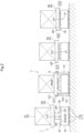
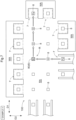
- a transport facility 100 includes transfer points 7 having placement surfaces 7f on which articles 9 are to be placed, and transport vehicles 1 each including a transfer device 20 that transfers an article 9 to and from a transfer point 7 and a carriage body 10 that travels while supporting the transfer device 20, as shown in FIGS. 1 and 2 .
- the transport facility 100 of the present embodiment includes a control device C (see FIG. 4 ).
- the control device C is configured, for example, to manage a transport schedule for the entire facility and to give the transport vehicles 1 transport commands.
- the transport facility 100 of the present embodiment has a travel area RA in which the transport vehicle 1 travels, and a work area WA in which work for articles 9 is performed.
- the transport facility 100 of the present embodiment includes a carry-in section 61 in which articles 9 are carried in from outside the facility, a discharge section 62 in which articles 9 are discharged outside the facility, an automated storage (not shown) for storing articles 9, a loading section 51 in which articles 9 are loaded into the automated storage, and an unloading section 52 in which articles 9 are unloaded from the automated storage, as shown in FIG. 1 .
- the transport vehicle 1 When delivering an article 9 to the transfer point 7, the transport vehicle 1 enters between the plurality of article receivers 720 in a plan view with the support surface 21f, which is supporting the article 9, positioned at the first height H1.
- the first height H1 is set to a position higher than the upper end of the regulator 721 of each article receiver 720, as mentioned above. This can prevent the support 21 and the article 9 supported thereby from interfering with the regulator 721 while the transport vehicle 1 enters between the article receivers 720.
- the transport vehicle 1 When receiving an article 9 from the transfer point 7, the transport vehicle 1 that has entered between the plurality of article receivers 720 in a plan view raises the support surface 21f from the second height H2 or the third height H3 to the first height H1 to receive the article 9, and thereafter exits from between the article receivers 720 while maintaining the height of the support surface 21f at the first height H1. This can prevent the support 21 and the article 9 supported thereby from interfering with the regulator 721 while the transport vehicle 1 exits from between the article receivers 720.
- An article 9 is transferred in the carry-in section 61, the discharge section 62, the loading section 51, or the unloading section 52, among the transfer points 7, as follows. That is, the transport vehicle 1 transfers an article 9 to and from the transfer point 7 (the carry-in section 61, the discharge section 62, the loading section 51, or the unloading section 52) by raising and lowering the support surface 21f between the first height H1 and the second height H2 or the third height H3 with the support 21 positioned between the two transport units 710 in a plan view. When delivering the article 9 to the transfer point 7, the transport vehicle 1 enters between the two transport units 710 in a plan view with the support surface 21f, which is supporting the article 9, positioned at the first height H1.
- the transport vehicle 1 When receiving an article 9 from the transfer point 7, the transport vehicle 1 that has entered between the two transport units 710 in a plan view raises the support surface 21f from the second height H2 or the third height H3 to the first height H1 to receive the article 9, and thereafter exits from between the two transport units 710 while maintaining the height of the support surface 21f at the first height H1.
- the transport vehicle 1 of the present embodiment includes auxiliary supports 30 that assist the support 21 in supporting an article 9.
- Each auxiliary support 30 has an auxiliary support surface 30f whose height is fixed.
- the auxiliary supports 30 are fixed to the upper surface of the carriage body 10, and their positions relative to the carriage body 10 are fixed.
- auxiliary supports 30 of the present embodiment are separated from each other with the support 21 therebetween in a plan view, as shown in FIG. 3 .
- a plurality of (four in the example shown) auxiliary supports 30 are separated from each other around the support 21 in a plan view.
- the first height H1 and the second height H2 are higher than the height of the auxiliary support surfaces 30f, as shown in FIG. 2 .
- the third height H3 is the same as or lower than the height of the auxiliary support surfaces 30f.
- the third height H3 of the present embodiment is lower than the height of the auxiliary support surfaces 30f.
- the appropriate orientation (appropriate orientation in a plan view) of the article 9 is different for each of the plurality of transfer points 7.
- the transfer points 7 adjacent to the work area WA require the orientation of the article 9 to be suitable for performing the work for this article 9.
- the other transfer points 7, namely the carry-in section 61, the discharge section 62, the loading section 51, and the unloading section 52, require the orientation of the article 9 to be suitable for transporting this article 9.
- the transport vehicle 1 performs a turning operation on the spot to change the travel direction (see FIG. 3 ), as mentioned above.
- the orientation of the article 9 in a plan view is changed using the turning operation of the transport vehicle 1.
- the turning operation of the transport vehicle 1 is prevented from changing the orientation of the article 9 in a plan view. The following is the detailed description.
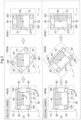
- the transport vehicle 1 performs at least two types of turning operations, namely a relative turning operation, which does not involve a change of the orientation of the article 9 in a plan view, and an integral turning operation, which involves a change of the orientation of the article 9 in a plan view.
- FIG. 3(a) shows the transport vehicle 1 performing the relative turning operation.
- FIG. 3(b) shows the transport vehicle 1 performing the integral turning operation.
- the support 21 is turned by the turner 23 in the opposite direction to the direction in which the carriage body 10 turns, independently of the turning of the carriage body 10 (see FIG. 3(a) ).
- the support 21 is not turned by the turner 23, but is turned by the turning of the carriage body 10, in the same direction as the turning direction of the carriage body 10 (see FIG. 3(b) ).
- half of the support 21 is hatched in order to facilitate the understanding of the orientation of the support 21.
- the transport vehicle 1 performs a turning operation (relative turning operation) with the support surface 21f positioned at the second height H2 in the case of changing the direction of the carriage body 10 without changing the orientation in a plan view of the article 9 supported by the support surface 21f by causing the turner 23 to turn the support 21 relative to the carriage body 10, as shown in FIGS. 2 and 3 .
- the article 9 is supported by the support 21 or the auxiliary support 30 (the carriage body 10) while the transport vehicle 1 supports the article 9.
- the article 9 is supported only by the support 21 while the support surface 21f is positioned at the second height H2, as mentioned above. In this case, the carriage body 10 (the auxiliary support 30) does not serve to support the article 9.
- positioning the support surface 21f at the second height H2 can prevent the directional change (turning) of the carriage body 10 from affecting the orientation of the article 9.
- the relative turning operation which does not involve a change of the orientation of the article 9 in a plan view, can thus be performed appropriately.
- the transport vehicle 1 of the present embodiment turns the support 21 in the opposite direction to the turning direction of the carriage body 10 at the same turning angle as the turning angle of the carriage body 10.
- the support 21 of the present embodiment has a regular N-sided polygonal shape (N is an integer greater than or equal to three) in a plan view, and the turner 23 turns the support 21 in 360/N degree increments relative to the carriage body 10. This allows the relationship in a plan view between the outer shape of the support 21 and the carriage body 10 to be the same even when the transport vehicle 1 performs a turning operation without the support 21 changing its orientation in a plan view.
- the transport vehicle 1 performs a turning operation (integral turning operation) with the support surface 21f positioned at the third height H3, as shown in FIGS. 2 and 3 . That is, the transport vehicle 1 performs a turning operation (integral turning operation) with the support surface 21f positioned at the third height H3 in the case of changing the orientation in a plan view of the article 9 supported by the support surface 21f in conjunction with the turning operation.
- the article 9 is supported by the support 21 or the auxiliary support 30 (carriage body 10) while the transport vehicle 1 supports the article 9, as mentioned above.
- the article 9 is supported only by the support 21 while the support surface 21f is positioned at the second height H2. Meanwhile, upon this support surface 21f being positioned at the third height H3, the article 9, which has been supported by the support surface 21f, is then supported by the auxiliary support surface 30f, which is positioned at a position higher than the third height H3. In this case, the support 21 does not serve to support the article 9. Therefore, positioning the support surface 21f at the third height H3 makes the orientation of the article 9 dependent on the directional change (turning) of the carriage body 10. The integral turning operation involving a change of the orientation of the article 9 in a plan view can thus be performed appropriately.
- the transport vehicle 1 turns the carriage body 10 clockwise by 90 degrees in a plan view.
- This turns the support 21, which is not driven by the turner 23, clockwise by 90 degrees together with the carriage body 10.
- the integral turning operation changes the orientation of the carriage body 10 and the orientation of the support 21 as shown in the figure.
- the carriage body 10 of the present embodiment can travel at a predetermined reference speed Vs (see FIG. 8 ), as shown in FIG. 1 .
- the reference speed Vs in this example is the highest speed of the carriage body 10.
- the reference speed Vs (the highest speed in this example) is determined as appropriate based on, for example, the management of the facility.
- the control device C (see FIG. 4 ) in this example can set the travel speed V of the carriage body 10 to the reference speed Vs.
- the letter "V" in FIG. 1 indicates the actual travel speed V of the carriage body 10. If the control device C sets the travel speed V of the carriage body 10 to the reference speed Vs, for example, the control device C performs feedback control on the travel speed V of the carriage body 10 with the reference speed Vs as a target value.
- the control device C of the present embodiment includes a host control device Ct that manages the entire facility, and a transport control device C1 that is installed in each transport vehicle 1 and controls functional units of the transport vehicle 1, as shown in FIG. 4 .
- the host control device Ct and the transport control device C1 communicate with each other.
- the host control device Ct designates the transport source Pd and the transport destination Pa of each article 9, and outputs a transport command designating the transport route R from the transport source Pd to the transport destination Pa to a corresponding transport control device C1 (the transport vehicle 1).
- the transport control device C1 that has received the transport command controls each functional unit of the transport vehicle 1 in which it is installed, in accordance with the transport command.
- the host control device Ct and the transport control device C1 each have a processor such as a microcomputer, and a peripheral circuit such as a memory, for example. Each function or processing is realized by cooperation of these pieces of hardware and programs executed on the processors such as a computer.
- the host control device Ct and the transport control device C1 may be collectively referred to simply as the "control device C".
- FIGS. 5 and 6 a description is given of an example in which the transport vehicle 1 transports an article 9 from a transport source Pd to a transport destination Pa, with reference to FIGS. 5 and 6 .
- the transport vehicle 1, the article 9, and other elements are omitted for convenience of illustration.
- FIG. 5 shows a transport route R of the transport vehicle 1 in the case where the orientation of the article 9 at the transfer point 7 serving as the transport source Pd is the same as the orientation of the article 9 at the transfer point 7 serving as the transport destination Pa.
- FIG. 6 shows the height of the support surface 21f, the set speed of the carriage body 10, and the operation of the transport vehicle 1 at each point along the transport route R in this case.
- the transport route R is set so as to connect the detection target section 8 at the transport source Pd, the detection target section 8 at a point A, the detection target section 8 at a point B, the detection target section 8 at a point C, and the detection target section 8 at the transport destination Pa.
- the transport vehicle 1 travels through the transport route R in the order from the transport source Pd to the point A, the point B, the point C, and the transport destination Pa.
- the transport vehicle 1 receives the article 9 from the transfer point 7 of the transport source Pd by changing the height of the support surface 21f from the third height H3 to the first height H1 at the transport source Pd, as shown in FIG. 6 .
- the travel speed V of the carriage body 10 at the transport source Pd is set lower than the reference speed Vs (V ⁇ Vs).
- the travel speed V of the transport vehicle 1 when receiving the article 9 from the transfer point 7 of the transport source Pd is set to zero. That is, the carriage body 10 is stopped.
- the transport vehicle 1 After receiving the article 9, the transport vehicle 1 starts traveling to the next point (the position of the detection target section 8) while supporting the article 9. In the example shown in FIG. 5 , the transport vehicle 1 starts traveling from the transport source Pd to the point A.
- the transport vehicle 1 travels with the support surface 21f positioned at the second height H2 if the straight distance L from the travel starting point (here, the transport source Pd) at which the transport vehicle 1 started traveling while supporting the article 9 to the directional change position 80 (here, the point B) at which the transport vehicle 1 is to perform a turning operation (relative turning operation) that does not involve a change of the orientation of the article 9 is within a predetermined distance Ls.
- the height of the support surface 21f may be changed to the second height H2 before the transport vehicle 1 starts traveling, or while the transport vehicle 1 travels after starting traveling. In the latter case, the transport vehicle 1 completes changing the height of the support surface 21f to the second height H2 before reaching the directional change position 80.
- the control device C of the present embodiment sets the transport route R from the transport source Pd to the transport destination Pa of the article 9, and determines whether the straight distance L is within the predetermined distance Ls based on the transport route R.
- the transport route R in this example is a route that combines a straight route along the first direction D1 and a straight route along the second direction D2, as mentioned above.
- the control device C calculates the straight distance L based on these straight routes that constitute the transport route R, and determines whether the straight distance L is within the predetermined distance Ls.
- the predetermined distance Ls is determined as appropriate, based on, for example, the management of the facility.
- the directional change position 80 that the transport vehicle 1 first reaches is the point B.
- the straight distance L from the transport source Pd, which is the travel starting point, to the point B is within the predetermined distance Ls (L ⁇ Ls). Accordingly, the transport vehicle 1 travels from the transport source Pd to the point B while positioning the support surface 21f at the second height H2.
- the transport vehicle 1 can position the support surface 21f at the second height H2 before reaching the directional change position 80 (the point B) where the transport vehicle 1 is to perform the relative turning operation.
- the transport vehicle 1 can therefore transition to the relative turning operation at the directional change position 80 (here, the point B) without changing the height of the support surface 21f. Consequently, the transport time of the article 9 can be shortened.
- the transport vehicle 1 in the example shown in FIGS. 5 and 6 changes the height of the support surface 21f from the first height H1 to the second height H2 while traveling from the transport source Pd to the point A.
- the travel speed V of the carriage body 10 at this time is set lower than the reference speed Vs (V ⁇ Vs).
- the transport vehicle 1 maintains the height of the support surface 21f at the second height H2.
- the travel speed V of the carriage body 10 at this time is set lower than the reference speed Vs (V ⁇ Vs). In this state, the transport vehicle 1 travels from the point A to the point B.
- the transport vehicle 1 maintains the height of the support surface 21f at the second height H2.
- the travel speed V of the carriage body 10 at this time is set lower than the reference speed Vs (V ⁇ Vs).
- the travel speed V at the point B is set to zero in this example.
- the transport vehicle 1, while stopped, performs the relative turning operation at the point B, which is the directional change position 80.
- the transport vehicle 1 thus directs the travel direction of the carriage body 10 to the next point C without changing the orientation of the article 9 in a plan view. Thereafter, the transport vehicle 1 starts traveling from the point B to the point C.
- the straight distance L from the travel starting point (here, the point B) of the transport vehicle 1 to the directional change position 80 (here, the point C) at which the transport vehicle 1 is to perform a turning operation (relative turning operation) that does not involve a change of the orientation of the article 9 is within the predetermined distance Ls (L ⁇ Ls). Accordingly, the transport vehicle 1 travels from the point B to the point C while positioning the support surface 21f at the second height H2.
- the travel starting point of the transport vehicle 1 is not limited to the starting point of the transport route R (the transport source Pd). If the transport vehicle 1 performs a turning operation, the straight distance L is determined with the point at which this turning operation was performed (in this example, the point B) as a travel starting point.
- the transport vehicle 1 changes the height of the support surface 21f from the second height H2 to the first height H1 while traveling from the point C to the transport destination Pa.
- the travel speed V of the carriage body 10 at this time is set lower than the reference speed Vs (V ⁇ Vs).
- the transport vehicle 1 delivers the article 9 to the transfer point 7 of the transport destination Pa by changing the height of the support surface 21f from the first height H1 to the third height H3.
- the travel speed V of the carriage body 10 at the transport destination Pa is set lower than the reference speed Vs (V ⁇ Vs).
- the travel speed V of the transport vehicle 1 while delivering the article 9 to the transfer point 7 of the transport destination Pa is set to zero. That is, the carriage body 10 is stopped.
- FIGS. 7 and 8 a description is given of an example in which the transport vehicle 1 transports an article 9 from a transport source Pd to a transport destination Pa, with reference to FIGS. 7 and 8 .
- the transport vehicle 1, the article 9, and other elements are omitted for convenience of illustration.
- FIG. 7 shows a transport route R of the transport vehicle 1 in the case where the orientation of the article 9 at the transfer point 7 serving as the transport source Pd is different from the orientation of the article 9 at the transfer point 7 serving as the transport destination Pa.
- FIG. 8 shows the height of the support surface 21f, the set speed of the carriage body 10, and the operation of the transport vehicle 1 at each point along the transport route R in this case.
- the transport route R is set so as to connect the detection target section 8 at the transport source Pd, the detection target section 8 at a point A, the detection target section 8 at a point B, the detection target section 8 at a point C, the detection target section 8 at a point D, and the detection target section 8 at the transport destination Pa.
- the transport vehicle 1 travels through the transport route R in the order from the transport source Pd to the point A, the point B, the point C, the point D, and the transport destination Pa.
- the transport vehicle 1 receives the article 9 from the transfer point 7 of the transport source Pd by changing the height of the support surface 21f from the third height H3 to the first height H1 at the transport source Pd, as shown in FIG. 8 .
- the travel speed V of the carriage body 10 at the transport source Pd is set lower than the reference speed Vs (V ⁇ Vs).
- the travel speed V of the transport vehicle 1 when receiving the article 9 from the transfer point 7 of the transport source Pd is set to zero. That is, the carriage body 10 is stopped.
- the transport vehicle 1 After receiving the article 9, the transport vehicle 1 starts traveling to the next point (the position of the detection target section 8) while supporting the article 9. In the example shown in FIG. 7 , the transport vehicle 1 starts traveling from the transport source Pd to the point A.
- the transport vehicle 1 travels with the support surface 21f positioned at the third height H3 regardless of whether the straight distance from the travel starting point (here, the transport source Pd) at which the transport vehicle 1 started traveling while supporting the article 9 to the directional change position 80 (here, the point B) at which the transport vehicle 1 is to perform a turning operation (integral turning operation) that involves a change of the orientation of the article 9 is within the predetermined distance.
- the directional change position 80 that the transport vehicle 1 first reaches is the point B, and the transport vehicle 1 is scheduled to perform at the point B the integral turning operation that involves a change of the orientation of the article 9.
- the transport vehicle 1 travels from the transport source Pd to the point B while positioning the support surface 21f at the third height H3.
- the transport vehicle 1 can position the support surface 21f at the third height H3 before reaching the directional change position 80 (the point B) at which the transport vehicle 1 is to perform the integral turning operation.
- the transport vehicle 1 can therefore transition to the integral turning operation at the directional change position 80 (here, the point B) without changing the height of the support surface 21f.
- the center of gravity of the transport vehicle 1 can be lowered by positioning the support surface 21f at the third height H3, thus allowing the transport vehicle 1 to travel at high speed while stabilizing the orientation of the article 9. Accordingly, the transport time of the article 9 can be shortened.
- the transport vehicle 1 in the example shown in FIGS. 7 and 8 changes the height of the support surface 21f from the first height H1 to the third height H3 while traveling from the transport source Pd to the point A.
- the travel speed V of the carriage body 10 at this time is set lower than the reference speed Vs (V ⁇ Vs).
- V ⁇ Vs the reference speed
- the support surface 21f is positioned at the first height H1
- the position of the article 9 supported by the support surface 21f is higher than while the support surface 21f is positioned at the second height H2 or the third height H3, making the orientation of the article 9 less stable accordingly.
- the carriage body 10 of the present embodiment travels at a speed lower than the reference speed Vs or stops in response to the lift 22 raising or lowering the support surface 21f between the first height H1 and the second height H2 or the third height H3. This makes it possible to change the height of the support surface 21f with high reliability in cases including a state where the height of the support surface 21f is set to the first height H1.
- the transport vehicle 1 maintains the height of the support surface 21f at the third height H3.
- the travel speed V of the carriage body 10 at this time is set lower than the reference speed Vs (V ⁇ Vs).
- the travel speed V at the point B is set to zero in this example.
- the transport vehicle 1, while stopped, performs the integral turning operation at the point B, which is the directional change position 80.
- the transport vehicle 1 thus directs the travel direction of the carriage body 10 to the point C and changes the orientation of the article 9 to the proper orientation at the transport destination Pa. Thereafter, the transport vehicle 1 starts traveling from the point B to the point C.
- the transport vehicle 1 maintains the height of the support surface 21f at the third height H3.
- the transport vehicle 1 maintains the height of the support surface 21f at the third height H3.
- the transport vehicle 1 changes the height of the support surface 21f from the third height H3 to the first height H1 while traveling from the point D to the transport destination Pa.
- the travel speed V of the carriage body 10 at this time is set lower than the reference speed Vs (V ⁇ Vs).
- the transport vehicle 1 delivers the article 9 to the transfer point 7 of the transport destination Pa by changing the height of the support surface 21f from the first height H1 to the third height H3.
- the travel speed V of the carriage body 10 at the transport destination Pa is set lower than the reference speed Vs (V ⁇ Vs).
- the travel speed V of the transport vehicle 1 while delivering the article 9 to the transfer point 7 of the transport destination Pa is set to zero. That is, the carriage body 10 is stopped.
- FIGS. 9 and 10 a description is given of an example in which the transport vehicle 1 transports the article 9 from the transport source Pd to the transport destination Pa, with reference to FIGS. 9 and 10 .
- the transport vehicle 1, the article 9, and other elements are omitted for convenience of illustration.
- the directional change position 80 that the transport vehicle 1 first reaches is the point B.
- the straight distance L from the transport source Pd, which is the travel starting point, to the point B is within the predetermined distance Ls (L ⁇ Ls). Accordingly, the transport vehicle 1 travels from the transport source Pd to the point B while positioning the support surface 21f at the second height H2.
- the transport vehicle 1 maintains the height of the support surface 21f at the second height H2.
- the travel speed V of the carriage body 10 at this time is set lower than the reference speed Vs (V ⁇ Vs). In this state, the transport vehicle 1 travels from the point A to the point B.
- the transport vehicle 1 maintains the height of the support surface 21f at the second height H2.
- the travel speed V of the carriage body 10 at this time is set lower than the reference speed Vs (V ⁇ Vs).
- the travel speed V at the point B is set to zero in this example.
- the transport vehicle 1, while stopped, performs the relative turning operation at the point B, which is the directional change position 80.
- the transport vehicle 1 thus directs the travel direction of the carriage body 10 to the next point C without changing the orientation of the article 9 in a plan view. Thereafter, the transport vehicle 1 starts traveling from the point B to the point C.
- the transport vehicle 1 travels with the support surface 21f positioned at the third height H3 if the straight distance L from the travel starting point (here, the point B) at which the transport vehicle 1 started traveling while supporting the article 9 to the directional change position 80 (here, the point E) at which the transport vehicle 1 is to perform a turning operation (relative turning operation) that does not involve a change of the orientation of the article 9 is longer than the predetermined distance Ls. If the straight distance L is longer than the predetermined distance Ls as in this case, and if the support surface 21f is not positioned at the third height H3 at the travel starting point, the height of the support surface 21f may be changed to the third height H3 before the transport vehicle 1 starts traveling or while the transport vehicle 1 travels after starting traveling.
- the transport vehicle 1 completes changing the height of the support surface 21f to the third height H3 before reaching the directional change position 80. If the straight distance L is longer than the predetermined distance Ls, the transport vehicle 1 can contribute more to shortening the transport time of the article 9 by traveling at high speed with the height of the support surface 21f set to the third height H3, which is lower than the second height H2, even if the support surface 21f needs to be positioned at the second height H2 later (i.e., the support surface 21f needs to be positioned at the second height H2 in the case of performing the relative turning operation).
- the center of gravity of the transport vehicle 1 can be lowered by positioning the support surface 21f at the third height H3, allowing the transport vehicle 1 to travel at high speed while stabilizing the orientation of the article 9, as mentioned above.
- the transport vehicle 1 of the present embodiment travels at the reference speed Vs if the straight distance L is longer than the predetermined distance Ls.
- the straight distance L from the point B, which is the travel starting point, to the point E, which is the next directional change position 80 is longer than the predetermined distance Ls (L>Ls). Accordingly, the transport vehicle 1 travels from the point B to the point E at the reference speed Vs while positioning the support surface 21f at the third height H3.
- the transport vehicle 1 changes the height of the support surface 21f from the second height H2 to the third height H3 while traveling from the point B to the point C. That is, the lift 22 of the present embodiment raises and lowers the support surface 21f between the second height H2 and the third height H3 while the carriage body 10 travels. Changing the height of the support surface 21f between the second height H2 and the third height H3 does not include a state where the height of the support surface 21f is the first height H1, thereby allowing the orientation of the article 9 to be stabilized relatively easily. Raising and lowering the support surface 21f between the second height H2 and the third height H3 while the carriage body 10 travels can contribute to shortening the transport time of the article 9 as in the above configuration.
- the travel speed V while the support surface 21f is raised and lowered between the second height H2 and the third height H3 while the transport vehicle 1 travels i.e., in the example shown in FIG. 9 , the travel speed V while the transport vehicle 1 travels from the point B to the point C, is set to the reference speed Vs.
- the travel speed V may be set lower than the reference speed Vs.
- the transport vehicle 1 maintains the height of the support surface 21f at the third height H3.
- the transport vehicle 1 maintains the height of the support surface 21f at the third height H3.
- the point E is the directional change position 80 at which the transport vehicle 1 is to perform the relative turning operation that does not involve a change of the orientation of the article 9.
- the support surface 21f needs to be positioned at the second height H2.
- the transport vehicle 1 changes the height of the support surface 21f from the third height H3 to the second height H2 while traveling from the point D to the point E. It is relatively easy to stabilize the orientation of the article 9 while changing the height of the support surface 21f between the second height H2 and the third height H3, as mentioned above.
- the transport vehicle 1 maintains the height of the support surface 21f at the second height H2.
- the travel speed V of the carriage body 10 at this time is set lower than the reference speed Vs (V ⁇ Vs).
- the travel speed V at the point E is set to zero in this example.
- the transport vehicle 1, while stopped, performs the relative turning operation at the point E, which is the directional change position 80.
- the transport vehicle 1 thus directs the travel direction of the carriage body 10 to the transport destination Pa without changing the orientation of the article 9 in a plan view. Thereafter, the transport vehicle 1 starts traveling from the point E to the transport destination Pa.
- the transport vehicle 1 changes the height of the support surface 21f from the second height H2 to the first height H1 while traveling from the point E to the transport destination Pa.
- the travel speed V of the carriage body 10 at this time is set lower than the reference speed Vs (V ⁇ Vs).
- the transport vehicle 1 delivers the article 9 to the transfer point 7 of the transport destination Pa by changing the height of the support surface 21f from the first height H1 to the third height H3.
- the travel speed V of the carriage body 10 at the transport destination Pa is set lower than the reference speed Vs (V ⁇ Vs).
- the travel speed V of the transport vehicle 1 while delivering the article 9 to the transfer point 7 of the transport destination Pa is set to zero. That is, the carriage body 10 is stopped.
- the above-described transport facility 100 can shorten the transport time of the article 9.
- a transport facility includes:
- the travel speed of the transport vehicle is unlikely to be high if the straight distance is within the predetermined distance.
- the carriage body can travel without making the orientation of the article unstable.
- the transport vehicle can reach the directional change position where the transport vehicle is to perform the turning operation while maintaining the height of the support surface at the second height.
- the transport vehicle can transition to the turning operation at this directional change position without changing the height of the support surface. Accordingly, the transport time of the article can be shortened.
- the center of gravity of the transport vehicle can be lowered by positioning the support surface to the third height if the straight distance is longer than the predetermined distance. The transport vehicle can therefore travel at high speed while stabilizing the orientation of the article. Accordingly, the transport time of the article can also be shortened from this point.
- the carriage body is capable of traveling at a predetermined reference speed, and the carriage body travels at a speed lower than the reference speed or stops while the lift raises and lowers the support surface between the first height and the second height or the third height.
- the position of the article supported by the support surface is higher than while the support surface is positioned at the second or third height, making the orientation of the article less stable accordingly.
- this configuration if the height of the support surface is changed, and this change includes a state where the height of the support surface is the first height, the carriage body travels at a speed lower than the reference speed, or stops. Therefore, it is possible to change the height of the support surface with high reliability in cases including a state where the height of the support surface is the first height.
- the lift raises and lowers the support surface between the second height and the third height while the carriage body travels.
- the orientation of the article can easily be stabilized in the case of performing a change of the height of the support surface between the second height and the third height that does not include a state where the height of the support surface is the first height.
- the travel of the carriage body and the change of the height of the support surface can be performed at the same time by changing the height of the support surface while the carriage body travels. This makes it easy to shorten the transport time.
- the transport vehicle includes auxiliary supports configured to assist the support in supporting the article,
- the article can be supported using the auxiliary support surface with the support surface positioned at the third height, thereby supporting the article more stably.
- the transport vehicle performs the turning operation with the support surface positioned at the third height in response to changing the orientation in a plan view of the article supported by the support surface in conjunction with the turning operation.
- the orientation in a plan view of the article can be changed together with the orientation of the carriage body due to the transport vehicle performing the turning operation while supporting the article using the auxiliary support surface by positioning the support surface at the third height.
- the orientation in a plan view of the article can be changed to an orientation suitable for the transfer point by the turning operation of the transport vehicle.
- the transport facility further includes a control device, and the control device sets a transport route from a transport source to a transport destination of the article, and determines based on the transport route whether the straight distance is within the predetermined distance.
- control device can more appropriately determine whether the straight distance is within the predetermined distance.
- the transport vehicle includes a detector
- a relatively simple configuration allows the traveling position of the transport vehicle to be controlled with high accuracy. Further, it is easy to flexibly change the transport route and the directional change position of the transport vehicle in accordance with, for example, the management situation of the facility.
- the support has a regular N-sided polygonal shape (N is an integer greater than or equal to three) in a plan view, and the turner turns the support in 360/N degree increments relative to the carriage body.
- the transfer point includes:
- the plurality of article receivers each have a regulator protruding upward from the placement surface and configured to regulate a position in a horizontal direction of the article placed on the placement surface, and the first height is set to a position higher than an upper end of the regulator.
- the regulator can regulate the position in the horizontal direction of the article placed at the transfer point. Further, it is possible to prevent the support and the regulator from interfering with each other even while the transport vehicle moves in and out of the transfer point with the support surface positioned at the first height.
- the technology according to the present disclosure can be applied to a transport facility that includes a transfer point having a placement surface on which an article is placed, and a transport vehicle including a transfer device configured to transfer the article to and from the transfer point and a carriage body configured to travel while supporting the transfer device.
Landscapes
- Engineering & Computer Science (AREA)
- Mechanical Engineering (AREA)
- Transportation (AREA)
- Structural Engineering (AREA)
- Civil Engineering (AREA)
- Life Sciences & Earth Sciences (AREA)
- Geology (AREA)
- Radar, Positioning & Navigation (AREA)
- Aviation & Aerospace Engineering (AREA)
- Remote Sensing (AREA)
- Physics & Mathematics (AREA)
- General Physics & Mathematics (AREA)
- Automation & Control Theory (AREA)
- Control Of Position, Course, Altitude, Or Attitude Of Moving Bodies (AREA)
- Warehouses Or Storage Devices (AREA)
- Intermediate Stations On Conveyors (AREA)
Applications Claiming Priority (2)
| Application Number | Priority Date | Filing Date | Title |
|---|---|---|---|
| JP2022087758A JP7528984B2 (ja) | 2022-05-30 | 2022-05-30 | 搬送設備 |
| PCT/JP2023/005933 WO2023233731A1 (fr) | 2022-05-30 | 2023-02-20 | Installation de transport |
Publications (2)
| Publication Number | Publication Date |
|---|---|
| EP4520687A1 true EP4520687A1 (fr) | 2025-03-12 |
| EP4520687A4 EP4520687A4 (fr) | 2026-04-29 |
Family
ID=89026022
Family Applications (1)
| Application Number | Title | Priority Date | Filing Date |
|---|---|---|---|
| EP23815495.9A Pending EP4520687A4 (fr) | 2022-05-30 | 2023-02-20 | Installation de transport |
Country Status (7)
| Country | Link |
|---|---|
| US (1) | US20250333275A1 (fr) |
| EP (1) | EP4520687A4 (fr) |
| JP (2) | JP7528984B2 (fr) |
| KR (1) | KR20250013175A (fr) |
| CN (1) | CN119301049A (fr) |
| TW (1) | TW202346172A (fr) |
| WO (1) | WO2023233731A1 (fr) |
Family Cites Families (5)
| Publication number | Priority date | Publication date | Assignee | Title |
|---|---|---|---|---|
| JP2009263059A (ja) * | 2008-04-23 | 2009-11-12 | Murata Mach Ltd | 搬送車 |
| JP6571916B2 (ja) * | 2014-08-27 | 2019-09-04 | 株式会社日立製作所 | 入出荷支援システム及び入出荷支援方法 |
| JP6969512B2 (ja) * | 2018-07-05 | 2021-11-24 | 株式会社ダイフク | 物品搬送装置 |
| JP7172528B2 (ja) * | 2018-12-06 | 2022-11-16 | 村田機械株式会社 | 搬送車 |
| JP7255401B2 (ja) * | 2019-07-18 | 2023-04-11 | 村田機械株式会社 | 搬送車 |
-
2022
- 2022-05-30 JP JP2022087758A patent/JP7528984B2/ja active Active
-
2023
- 2023-02-20 CN CN202380044177.9A patent/CN119301049A/zh active Pending
- 2023-02-20 WO PCT/JP2023/005933 patent/WO2023233731A1/fr not_active Ceased
- 2023-02-20 US US18/870,183 patent/US20250333275A1/en active Pending
- 2023-02-20 EP EP23815495.9A patent/EP4520687A4/fr active Pending
- 2023-02-20 KR KR1020247040210A patent/KR20250013175A/ko active Pending
- 2023-02-23 TW TW112106616A patent/TW202346172A/zh unknown
-
2024
- 2024-07-11 JP JP2024111747A patent/JP7677513B2/ja active Active
Also Published As
| Publication number | Publication date |
|---|---|
| US20250333275A1 (en) | 2025-10-30 |
| TW202346172A (zh) | 2023-12-01 |
| EP4520687A4 (fr) | 2026-04-29 |
| CN119301049A (zh) | 2025-01-10 |
| KR20250013175A (ko) | 2025-01-31 |
| JP7528984B2 (ja) | 2024-08-06 |
| JP7677513B2 (ja) | 2025-05-15 |
| JP2024133201A (ja) | 2024-10-01 |
| JP2023175351A (ja) | 2023-12-12 |
| WO2023233731A1 (fr) | 2023-12-07 |
Similar Documents
| Publication | Publication Date | Title |
|---|---|---|
| US11427449B2 (en) | Forklift apparatus, forklift control method, and non-transitory computer-readable medium | |
| JP7557954B2 (ja) | 制御装置、移動制御システム、制御方法及びプログラム | |
| WO2022206791A1 (fr) | Système et procédé de prélèvement | |
| JP2009035403A (ja) | 搬送システム、及び該搬送システムにおける教示方法 | |
| CN118524969A (zh) | 用于在订单拣选系统中运输装载物的托盘、卸载装置和装载装置 | |
| US12077377B2 (en) | Transport vehicle | |
| JP7584902B2 (ja) | 自動倉庫システム | |
| CN116710372B (zh) | 运送装置、运送系统和运送装置的控制方法 | |
| EP4520687A1 (fr) | Installation de transport | |
| JP2007246226A (ja) | 物品卸し装置及びその物品卸し装置を備えた物品収納設備 | |
| CN113655782A (zh) | 终端、控制系统、控制方法以及程序 | |
| JP5045186B2 (ja) | スタッカクレーン及び自動倉庫 | |
| JP7555800B2 (ja) | 対象物の配置位置決定方法、制御装置、プログラム、荷役装置、及び、荷役システム | |
| CN119305895A (zh) | 搬运控制方法、装置、系统和计算机可读存储介质 | |
| EP4585486A1 (fr) | Système de chariot guidé par rail | |
| CN116300952A (zh) | 穿梭车的运动控制方法、装置、计算机设备及存储介质 | |
| CN118205854A (zh) | 一种停靠点机器人的位姿调整方法、系统及装置 | |
| EP4613673A1 (fr) | Installation de transport d?articles | |
| JPH0659938B2 (ja) | パレタイジング・システム | |
| JP7611183B2 (ja) | 情報処理装置、移動制御システム、情報処理方法及びプログラム | |
| TW202610921A (zh) | 搬送設備 | |
| JP2009190805A (ja) | 自動倉庫及び自動倉庫の荷搬送方法 | |
| CN116867716A (zh) | 货物搬送系统及搬送体 | |
| JP2026037639A (ja) | 搬送装置および搬送制御装置 | |
| WO2026048826A1 (fr) | Système de transport et procédé de transport |
Legal Events
| Date | Code | Title | Description |
|---|---|---|---|
| STAA | Information on the status of an ep patent application or granted ep patent |
Free format text: STATUS: THE INTERNATIONAL PUBLICATION HAS BEEN MADE |
|
| PUAI | Public reference made under article 153(3) epc to a published international application that has entered the european phase |
Free format text: ORIGINAL CODE: 0009012 |
|
| STAA | Information on the status of an ep patent application or granted ep patent |
Free format text: STATUS: REQUEST FOR EXAMINATION WAS MADE |
|
| 17P | Request for examination filed |
Effective date: 20241206 |
|
| AK | Designated contracting states |
Kind code of ref document: A1 Designated state(s): AL AT BE BG CH CY CZ DE DK EE ES FI FR GB GR HR HU IE IS IT LI LT LU LV MC ME MK MT NL NO PL PT RO RS SE SI SK SM TR |
|
| DAV | Request for validation of the european patent (deleted) | ||
| DAX | Request for extension of the european patent (deleted) | ||
| A4 | Supplementary search report drawn up and despatched |
Effective date: 20260327 |
|
| RIC1 | Information provided on ipc code assigned before grant |
Ipc: B65G 1/00 20060101AFI20260323BHEP Ipc: B65G 65/00 20060101ALI20260323BHEP |