EP4520688A1 - Handhabungssystem und -verfahren - Google Patents
Handhabungssystem und -verfahren Download PDFInfo
- Publication number
- EP4520688A1 EP4520688A1 EP24198994.6A EP24198994A EP4520688A1 EP 4520688 A1 EP4520688 A1 EP 4520688A1 EP 24198994 A EP24198994 A EP 24198994A EP 4520688 A1 EP4520688 A1 EP 4520688A1
- Authority
- EP
- European Patent Office
- Prior art keywords
- substantially flat
- conveyor
- flat article
- conveying direction
- station
- Prior art date
- Legal status (The legal status is an assumption and is not a legal conclusion. Google has not performed a legal analysis and makes no representation as to the accuracy of the status listed.)
- Pending
Links
Images



Classifications
-
- B—PERFORMING OPERATIONS; TRANSPORTING
- B65—CONVEYING; PACKING; STORING; HANDLING THIN OR FILAMENTARY MATERIAL
- B65G—TRANSPORT OR STORAGE DEVICES, e.g. CONVEYORS FOR LOADING OR TIPPING, SHOP CONVEYOR SYSTEMS OR PNEUMATIC TUBE CONVEYORS
- B65G1/00—Storing articles, individually or in orderly arrangement, in warehouses or magazines
- B65G1/02—Storage devices
- B65G1/04—Storage devices mechanical
- B65G1/137—Storage devices mechanical with arrangements or automatic control means for selecting which articles are to be removed
- B65G1/1373—Storage devices mechanical with arrangements or automatic control means for selecting which articles are to be removed for fulfilling orders in warehouses
- B65G1/1378—Storage devices mechanical with arrangements or automatic control means for selecting which articles are to be removed for fulfilling orders in warehouses the orders being assembled on fixed commissioning areas remote from the storage areas
-
- B—PERFORMING OPERATIONS; TRANSPORTING
- B65—CONVEYING; PACKING; STORING; HANDLING THIN OR FILAMENTARY MATERIAL
- B65B—MACHINES, APPARATUS OR DEVICES FOR, OR METHODS OF, PACKAGING ARTICLES OR MATERIALS; UNPACKING
- B65B27/00—Bundling particular articles presenting special problems using string, wire, or narrow tape or band; Baling fibrous material, e.g. peat, not otherwise provided for
- B65B27/02—Bundling bricks or other building blocks
-
- B—PERFORMING OPERATIONS; TRANSPORTING
- B65—CONVEYING; PACKING; STORING; HANDLING THIN OR FILAMENTARY MATERIAL
- B65G—TRANSPORT OR STORAGE DEVICES, e.g. CONVEYORS FOR LOADING OR TIPPING, SHOP CONVEYOR SYSTEMS OR PNEUMATIC TUBE CONVEYORS
- B65G47/00—Article or material-handling devices associated with conveyors; Methods employing such devices
- B65G47/52—Devices for transferring articles or materials between conveyors i.e. discharging or feeding devices
-
- B—PERFORMING OPERATIONS; TRANSPORTING
- B65—CONVEYING; PACKING; STORING; HANDLING THIN OR FILAMENTARY MATERIAL
- B65G—TRANSPORT OR STORAGE DEVICES, e.g. CONVEYORS FOR LOADING OR TIPPING, SHOP CONVEYOR SYSTEMS OR PNEUMATIC TUBE CONVEYORS
- B65G47/00—Article or material-handling devices associated with conveyors; Methods employing such devices
- B65G47/52—Devices for transferring articles or materials between conveyors i.e. discharging or feeding devices
- B65G47/53—Devices for transferring articles or materials between conveyors i.e. discharging or feeding devices between conveyors which cross one another
- B65G47/54—Devices for transferring articles or materials between conveyors i.e. discharging or feeding devices between conveyors which cross one another at least one of which is a roller-way
-
- B—PERFORMING OPERATIONS; TRANSPORTING
- B65—CONVEYING; PACKING; STORING; HANDLING THIN OR FILAMENTARY MATERIAL
- B65G—TRANSPORT OR STORAGE DEVICES, e.g. CONVEYORS FOR LOADING OR TIPPING, SHOP CONVEYOR SYSTEMS OR PNEUMATIC TUBE CONVEYORS
- B65G47/00—Article or material-handling devices associated with conveyors; Methods employing such devices
- B65G47/74—Feeding, transfer, or discharging devices of particular kinds or types
- B65G47/90—Devices for picking-up and depositing articles or materials
- B65G47/91—Devices for picking-up and depositing articles or materials incorporating pneumatic, e.g. suction, grippers
-
- B—PERFORMING OPERATIONS; TRANSPORTING
- B65—CONVEYING; PACKING; STORING; HANDLING THIN OR FILAMENTARY MATERIAL
- B65G—TRANSPORT OR STORAGE DEVICES, e.g. CONVEYORS FOR LOADING OR TIPPING, SHOP CONVEYOR SYSTEMS OR PNEUMATIC TUBE CONVEYORS
- B65G47/00—Article or material-handling devices associated with conveyors; Methods employing such devices
- B65G47/74—Feeding, transfer, or discharging devices of particular kinds or types
- B65G47/90—Devices for picking-up and depositing articles or materials
- B65G47/91—Devices for picking-up and depositing articles or materials incorporating pneumatic, e.g. suction, grippers
- B65G47/912—Devices for picking-up and depositing articles or materials incorporating pneumatic, e.g. suction, grippers provided with drive systems with rectilinear movements only
-
- B—PERFORMING OPERATIONS; TRANSPORTING
- B65—CONVEYING; PACKING; STORING; HANDLING THIN OR FILAMENTARY MATERIAL
- B65G—TRANSPORT OR STORAGE DEVICES, e.g. CONVEYORS FOR LOADING OR TIPPING, SHOP CONVEYOR SYSTEMS OR PNEUMATIC TUBE CONVEYORS
- B65G47/00—Article or material-handling devices associated with conveyors; Methods employing such devices
- B65G47/74—Feeding, transfer, or discharging devices of particular kinds or types
- B65G47/90—Devices for picking-up and depositing articles or materials
- B65G47/91—Devices for picking-up and depositing articles or materials incorporating pneumatic, e.g. suction, grippers
- B65G47/915—Devices for picking-up and depositing articles or materials incorporating pneumatic, e.g. suction, grippers provided with drive systems with rotary movements only
-
- B—PERFORMING OPERATIONS; TRANSPORTING
- B65—CONVEYING; PACKING; STORING; HANDLING THIN OR FILAMENTARY MATERIAL
- B65B—MACHINES, APPARATUS OR DEVICES FOR, OR METHODS OF, PACKAGING ARTICLES OR MATERIALS; UNPACKING
- B65B23/00—Packaging fragile or shock-sensitive articles other than bottles; Unpacking eggs
- B65B23/20—Packaging plate glass, tiles, or shingles
-
- B—PERFORMING OPERATIONS; TRANSPORTING
- B65—CONVEYING; PACKING; STORING; HANDLING THIN OR FILAMENTARY MATERIAL
- B65G—TRANSPORT OR STORAGE DEVICES, e.g. CONVEYORS FOR LOADING OR TIPPING, SHOP CONVEYOR SYSTEMS OR PNEUMATIC TUBE CONVEYORS
- B65G2201/00—Indexing codes relating to handling devices, e.g. conveyors, characterised by the type of product or load being conveyed or handled
- B65G2201/02—Articles
- B65G2201/0214—Articles of special size, shape or weigh
- B65G2201/022—Flat
Definitions
- This invention relates to a handling system and method for handling substantially flat articles; more specifically, substantially flat ceramic articles such as, for example, ceramic slabs or tiles.
- this invention relates to a handling system and method that is particularly suitable for handling, or moving from one place to another, substantially flat articles in order to form an order to be shipped; more specifically, a multi-reference order to be shipped, or formed from a plurality of substantially flat articles that (at least some of which) have different features, for example different colours, aesthetic designs, formats, and/or materials.
- the handling process for substantially flat articles to form orders to be shipped has some intrinsic critical issues linked to the dimensions of handling systems and any storage systems, as well as to all the issues linked to the logistics of substantially flat articles and to subsequent operations for organising these articles to form orders to be shipped. These issues are amplified in the case of handling substantially flat articles with large dimensions and/or in the case wherein the order to be shipped is a multi-reference order.
- handling systems for flat articles involve collecting the flat articles, typically by means of special gripping devices, for example equipped with suction cups or grippers, which are manually driven, for example when they are integrated into gripping vehicles, or automatically, to transfer the articles, possibly with the support, from the storage warehouse or production line, towards subsequent processing stations, where the articles are first suitably grouped, generally manually, to form orders to be shipped and are then packaged, for example by winding them with packaging film and/or with holding straps to ensure their position.
- special gripping devices for example equipped with suction cups or grippers, which are manually driven, for example when they are integrated into gripping vehicles, or automatically, to transfer the articles, possibly with the support, from the storage warehouse or production line, towards subsequent processing stations, where the articles are first suitably grouped, generally manually, to form orders to be shipped and are then packaged, for example by winding them with packaging film and/or with holding straps to ensure their position.
- the purpose of this invention is to provide a handling system and method for substantially flat articles, which make it possible to overcome, at least partially, the drawbacks of the prior art, proposing an alternative solution that makes it possible to automate the flat article handling operations quickly and safely, while restricting the dimensions and time necessary for forming an order to be shipped.
- an article handling system and method for handling substantially flat articles in order to form an order to be shipped are provided, according to what is claimed in the appended independent claims, and preferably, in any one of the claims depending directly or indirectly on the above-mentioned independent claims.
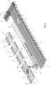
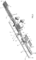
- reference number 1 indicates, as a whole, a handling system for handling substantially flat articles 2 in order to form at least one order to be shipped 3.
- the term "handling” means all the operations involving taking, moving, positioning, and organising into groups the substantially flat articles 2; more advantageously, the term “handling” means all the operations needed to form an order to be shipped 3, including a plurality of substantially flat articles 2, possibly different ones, for example due to their colour, format, etc., more advantageously, organised (or arranged according to a defined criterion and/or orientation) on a support 4, which advantageously but without imposing limits is a rack, as illustrated in the attached figures, or a pallet, or a crate.
- the substantially flat articles 2 referred to in this discussion are plate-shaped articles 2, which have two dimensions that are much greater than the third dimension, or have dimensions in plan that are much greater than the thickness. More specifically, advantageously but without imposing limits, each of these substantially flat articles 2 comprises two main surfaces that are parallel, face each other, and connected by at least four side surfaces orthogonal to the main surfaces and in pairs that are parallel and face each other; in other words, advantageously but without imposing limits, each of these (substantially) flat articles 2 has a (substantially) parallelepiped shape.
- the substantially flat articles 2 are articles 2 from the ceramics processing sector like, for example, ceramic slabs and/or tiles or piles or bundles of ceramic slabs and/or tiles of the same type.
- the handling system 1 comprises a plurality of storage units 5, each comprising at least one substantially flat article 2 of a certain type, in particular a pile of substantially flat articles 2 of a certain type (as illustrated in the attached figures); a conveyor 6 that extends from an inlet station 7 to an intermediate station 8 in a conveying direction A along a section T1 of a given path P and is configured to support and convey at least one substantially flat article 2 along this section T1 of the given path P; a gripping device 9 operationally interposed between the storage units 5 and the conveyor 6 and which can be operated to hold at least one substantially flat article 2 from one of the storage units 5 and release it on this conveyor 6.
- the conveyor 6 comprises (in particular, is) a conveyor system, for example, in the example illustrated, a roller conveyor.
- the handling system 1 also comprises: an additional conveyor 10 that extends from the intermediate station 8 to an additional station 11 in a conveying direction B, orthogonal to the conveying direction A, and is configured to support and convey at least one substantially flat article 2 along a second section T2 of the above-mentioned given path P; a forming unit 12 to form an order to be shipped 3, which comprises at least one support 13 intended to receive at least one substantially flat article 2 to be shipped; and an additional gripping device 14 operationally interposed between the conveyor 10 and the forming unit 12 and which can be operated to take a substantially flat article 2 from the conveyor 10 (in particular, from the station 11) and release it so that it rests on the support 13 of the forming unit 12.
- an additional conveyor 10 that extends from the intermediate station 8 to an additional station 11 in a conveying direction B, orthogonal to the conveying direction A, and is configured to support and convey at least one substantially flat article 2 along a second section T2 of the above-mentioned given path P
- a forming unit 12 to form
- the handling system 1 comprises a control unit CU configured to control the driving and operation of the monitoring system 1 so as to enable the automatic formation of the order to be shipped 3.
- the control unit CU is configured to receive, for example by means of a user interface or by means of a connection, for example a wireless one, with other control systems (not illustrated), data regarding the order to be shipped 3 that must be formed (in particular, these data comprise at least the number and type of substantially flat articles 2 that must form this order to be shipped 3) so as to control, as a result, at least the gripping device 9, in particular all the various components of the handling system 1 so as to form the order to be shipped 3.
- control unit CU is configured to operate: the gripping device 9 so that it takes at least one substantially flat article 2 of a given type from one of the storage units 5 and releases it onto the conveyor 6; the conveyor 6 so as to convey this substantially flat article 2 towards the intermediate station 8; the conveyor 10 so as to convey this substantially flat article 2 from the intermediate station 8 towards the station 11; and the gripping device 14 so that it takes the substantially flat article 2 from the conveyor 10 and replaces it on the support 13 of the forming unit 12.
- control unit CU is configured to operate: the gripping device 9 so that this takes, potentially in subsequent steps (operations), from the respective storage stations 5 a given number of substantially flat articles 2 of a given type based on data regarding the order to be shipped 3 to be formed; the conveyors 6 and 10 so that they convey these substantially flat articles 2 along the given path P to the station 11; and the gripping device 14 to transfer each of these substantially flat articles 2 from the conveyor 10 on the support 13 of the forming unit 12.
- the forming unit 12 comprises at least two supports 13, of the same or a different type (as in the case illustrated in the attached figures) and the gripping device 14 is configured to position each substantially flat article 2 selectively on one or another support 13 based on the type of order to be shipped 3.
- the control unit CU is configured to control the gripping device 14 so that this selectively releases each substantially flat article 2 on one or another support 13.
- the gripping device 9 comprises: a first gripping head 15, which is configured to grab and release at least one substantially flat article 2; and a moving body 16, which is movable in a work area extending at least between the storage units 5 and the conveyor 6 so as to allow the transfer of substantially flat articles 2 between the storage units 5 and the conveyor 6.
- This work area of the gripping device 9 is the area inside which this gripping device 9 can move to take or release substantially flat articles 2.
- this work area comprises at least part of the storage units 5 so that this gripping device 9 can take a substantially flat article 2 from one storage unit 5, based on the order to be shipped 3 to be formed, and at least part of the conveyor 6 to be able to release the articles 2 taken onto it.
- each storage unit 5 comprises a support 17, for example a pallet, to support the substantially flat article 2 or the pile of substantially flat articles 2 of a given type and a moving assembly 18, advantageously but without imposing limits with tracks, configured to move this support 17 between a first position inside this work area of the gripping device 9 and a second position outside this work area.
- the moving assembly 18 is able to move the support 17 along a direction parallel to the conveying direction B, drawing closer to or further away from the conveyor 6 moving, respectively, from the second position to the first position or vice versa.
- This configuration makes it possible to position the substantially flat articles 2 on each storage unit 5, in particular on the support 17, when this support 17 is in the first position outside the work area of the gripping device 9 and, subsequently, by means of the moving assembly 18, to move this support 17 towards the first position where the substantially flat articles 2 can be taken by the first gripping device 9.
- This makes it possible, therefore, to reload each storage unit 5 completely safely even while the gripping device 9 takes the substantially flat articles from the adjacent storage units 5, eliminating the need to stop the handling operations for the time necessary to resupply the storage units 5, with a resulting increase in the efficiency of the handling system 1.
- the storage units 5 are arranged aligned with each other to form a row parallel to the conveying direction A (see, for example, Figures 1 , 2 , and 4 ); even more advantageously but without imposing limits, these storage units 5 are arranged on one side of the conveyor 10.
- the handling system 1 comprises a track 19, which is known, extending parallel to the conveying direction A, more advantageously between the conveyor 6 and the row of storage units 5; and the moving body 16 of the gripping device 9 is slidably coupled to this track 19 to enable the movement of the gripping head 15 inside the above-mentioned work area.
- the moving body 16 comprises (in particular, is) an anthropomorphic robot.
- the gripping head 15 comprises one or more suction cups that can be selectively operated to take or release at least one substantially flat article 2.
- the gripping head 15 comprises an articulated parallelogram that supports a plurality of suction cups placed at a mutual distance from each other that can be adjusted, for example depending on the format of the substantially flat article 2, suitably deforming the articulated parallelogram and/or adjusting the length of its branches in a known way.
- the gripping head 15 instead of the plurality of suction cups, comprises a plurality of suction heads that can be selectively operated to take or release a substantially flat article.
- the gripping head 15 comprises (in particular, is formed from) grippers.
- the gripping device 14 comprises: a gripping head 20 configured to grasp and release at least one substantially flat article 2; and a supporting structure 21 configured to carry, hanging, the gripping head 20 and enable its movement in a work area that extends at least between the conveyor 10 and the forming unit 12 so as to enable the transfer of the substantially flat articles 2 from this conveyor 10, in particular from the station 11 to the forming unit 12.
- the gripping head 20 of the gripping device 14 is similar to the gripping head 15 of the gripping device 9; thus, the same considerations mentioned above are true for the gripping head 15.
- the support structure 21 comprises (in particular, is formed from): a frame 22 that has at least one guide 23 (more advantageously, a pair of guides 23, as in the embodiment illustrated, each) extending parallel to the conveying direction B; a beam 24 slidably coupled to the guide 23 (in particular, to the pair of guides 23); and a known connection assembly 25, which is slidably coupled to the beam 24 and is configured to support the gripping head 20 so as to enable its movement along a direction Z, orthogonal both to the conveying direction A and to the conveying direction B.
- a frame 22 that has at least one guide 23 (more advantageously, a pair of guides 23, as in the embodiment illustrated, each) extending parallel to the conveying direction B; a beam 24 slidably coupled to the guide 23 (in particular, to the pair of guides 23); and a known connection assembly 25, which is slidably coupled to the beam 24 and is configured to support the gripping head 20 so as to enable its movement along a direction Z, orthogonal both to the conveying direction A and to
- this connection assembly 25 is configured to enable the movement of the gripping head 20 along the vertical direction Z to enable the movement of the gripping head 20 closer to/further away from the conveyor 10 and the above-mentioned at least one support 13 of the forming unit 12.
- connection assembly 25 comprises a joint to enable, if necessary, the rotation of the gripping head 20, for example, to enable the arrangement of the substantially flat article 2 edgeways, or resting on one of the side surfaces (see, for example, Figures 1 and 5 which illustrate an order to be shipped 3 that has substantially flat articles 2 placed edgeways).
- the support structure 21 of the gripping device 14 comprises (more specifically, is composed of) a three-axis Cartesian robot.
- the handling system 1 comprises an integrity control assembly 26 configured to inspect the substantially flat article 2 (in particular, each substantially flat article 2) that moves along the above-mentioned given path P and to identify any defects, thus identifying any defective articles 2; and a rejection device 27 that can be operated, based on what is detected by the integrity control assembly 26, to transfer any defective articles 2 (or articles 2 that have defects) to a rejection station 28.
- an integrity control assembly 26 configured to inspect the substantially flat article 2 (in particular, each substantially flat article 2) that moves along the above-mentioned given path P and to identify any defects, thus identifying any defective articles 2
- a rejection device 27 that can be operated, based on what is detected by the integrity control assembly 26, to transfer any defective articles 2 (or articles 2 that have defects) to a rejection station 28.
- the integrity control assembly 26 is arranged at the intermediate station 8 and comprises a gantry 29 extending above the conveyor 6 and supports at least one detector 30 (in particular, in the attached figure, a plurality of detectors 30, each) configured to inspect the transverse edges B1 of the substantially flat article 2 (in particular, of each substantially flat article 2 that moves on the conveyor 6), while this moves forward on the conveyor 6 along the section T1 of the given path P; or, the edges B1 that, in use (or while the article 2 moves forward along the section T1 in the conveying direction A), extend perpendicularly to the direction A and parallel to the conveying direction B; and a second gantry 31 extending above the conveyor 10 and supporting at least one additional detector 32 configured to inspect the longitudinal edges B2 of the substantially flat article 2 (in particular, of each substantially flat article 2 that moves on the conveyor 10), or the edges B2 that, in use (or while the article 2 is moved forward along the section T2 in the conveying direction B), extend orthogon
- the rejection device 27 is operationally connected to the conveyor 10.
- the conveyor 10 comprises (in particular, is composed of) a plurality of belts 33 extending parallel to the conveying direction B and defining a transport plane; and the rejection device 27 comprises a series of rollers 34 extending parallel to the conveying direction B that are arranged in succession along a direction C perpendicular to the direction B (and, advantageously but without imposing limits, parallel to the conveying direction A) between the belts 33.
- the rejection device 27 also comprises moving means (not visible in the attached figures and known) configured to move the plurality of rollers 34 between a rest position, wherein the rollers 34 are placed at a lower level with respect to the level of the belts 33 so as not to interfere with the transport plane, and an operating position wherein the rollers 34 are raised to a level at least equal to that of the belts 33 to receive the substantially flat article 2 resting on (in particular, for taking up from) the transport plane and convey it towards the rejection station 28.
- moving means not visible in the attached figures and known
- the rejection device 27 also comprises moving means (not visible in the attached figures and known) configured to move the plurality of rollers 34 between a rest position, wherein the rollers 34 are placed at a lower level with respect to the level of the belts 33 so as not to interfere with the transport plane, and an operating position wherein the rollers 34 are raised to a level at least equal to that of the belts 33 to receive the substantially flat article 2 resting on (in particular, for taking up from) the transport plane and
- the conveyor 10 comprises (in particular, is composed of) a plurality of rollers (in particular, these rollers are provided instead of the above-mentioned belts 33 or in combination with these belts 33).
- the rejection device 27 comprises: a series of rollers 34 extending parallel to the conveying direction B and are arranged in succession along a direction C perpendicular to the direction B (and, advantageously but without imposing limits, parallel to the conveying direction A) between the rollers, moving means (not visible in the attached figures and known) configured to move the plurality of rollers 34 between a rest position, wherein the rollers 34 are placed at a lower level with respect to the level of the rollers so as not to interfere with the transport plane, and an operating position wherein the rollers 34 are raised to a level at least equal to that of the rollers to receive the substantially flat article 2 resting on (in particular, to take up from) the transport plane and convey it towards the rejection station 28.
- the support 13 (in particular, at least one of the supports 13) of the forming unit 12 is configured to receive the substantially flat article 2 arranged edgeways.
- the support 13 (or each of at least one of the supports 13) is a support rack.
- the forming unit 12 comprises a strapping machine 35 (known and only partially and schematically illustrated in the attached figures but) configured to apply at least one sealing strap (for example, a band) around the substantially flat article 2 and to the support 4 that form the order to be shipped 3 to bind them together so as to ensure the stability of the order to be shipped 3.
- control unit CU is configured to operate the strapping machine 35 when the order to be shipped 3 is completed to apply the sealing strap between the support 4 (for example, the rack) and the substantially flat articles 2 so as to increase the stability of the articles and avoid the risk of the substantially flat articles 2 falling.
- supports 4 configured to receive the substantially flat articles 2 arranged edgeways, with resulting benefits in terms of dimensions with the same number of articles 2, ensuring greater stability of the order to be shipped 3.
- the forming unit 12 comprises a packaging unit (not illustrated in the attached figures) and configured to wind the order to be shipped 3 with a packaging film or with die cut cardboard once formed.
- the support 13 comprises (in particular, coincides with) the support 4 of the order to be shipped 3.
- the support 13 of the forming unit 12 is intended to support the support 4, when the order to be shipped 3 comprises it.
- the forming unit 12 also comprises a moving assembly, similar to the moving assembly 18, configured to move the support 13, or each of the supports 13, between a first position inside the work area of the gripping device 14 and a second position outside of this work area.
- a moving assembly similar to the moving assembly 18, configured to move the support 13, or each of the supports 13, between a first position inside the work area of the gripping device 14 and a second position outside of this work area.
- a handling method is proposed for handling substantially flat articles 2 and forming an order to be shipped 3, which advantageously but without imposing limits is implemented with a handling system 1 in accordance with one of the embodiments described above.
- this handling method comprises: a feeding step, during which a plurality of storage units 5 is provided, each comprising at least one substantially flat article 2 of a given type and, advantageously but without imposing limits, a support 13 (advantageously but without imposing limits of the type described above) to support the at least one substantially flat article 2; a transfer step, during which a gripping device 9, advantageously but without imposing limits implemented according to one of the embodiments described above, selectively takes at least one substantially flat article 2 from one of the storage units 5 and releases it on a conveyor 6, advantageously but without imposing limits of the type described above, which extends from one inlet station 5 to an intermediate station 8 along a first section T1 of a given path P in a first conveying direction A; and a first conveying step, which advantageously but without imposing limits is (at least partially) subsequent to the first transfer step, during which the conveyor 6 moves the substantially flat article 2 towards the intermediate station 8 in the conveying direction A.
- the handling method also comprises a second conveying step, during which a conveyor 10, advantageously but without imposing limits of the type described above, extending downstream of the conveyor 6 along the given path P defined by this intermediate station 8 to an additional station 11 in the above-mentioned conveying direction B, receives the substantially flat article 2 from the conveyor 6 and moves it towards the station 11 in the conveying direction B; and a forming step, during which a gripping device 14, advantageously but without imposing limits of the type described with respect to the handling system 1, takes the substantially flat article 2 from the conveyor 10 and transfers it to a forming unit 12 that comprises at least one support 13 and releases it on this support 13 for forming an order to be shipped 3.
- a second conveying step during which a conveyor 10, advantageously but without imposing limits of the type described above, extending downstream of the conveyor 6 along the given path P defined by this intermediate station 8 to an additional station 11 in the above-mentioned conveying direction B, receives the substantially flat article 2 from the conveyor 6 and moves it towards the station 11 in the conveying direction
- the first transfer step comprises, in turn, a first transfer sub-step, during which the gripping device 9 takes a first substantially flat article 2 from one storage unit 5 of the plurality of storage units 5, and releases it onto the conveyor 6 and at least one second transfer sub-step, (at least partially) subsequent to the first transfer sub-step, during which the gripping device 9 takes at least one second substantially flat article 2 from a storage unit 5, which, advantageously but without imposing limits, can be the same from which the first article 2 is taken (when the order to be shipped 3 is intended to comprise two articles 2 of the same time) or may came from another storage unit 5 (when the order to be shipped 3 is a multi-reference order).
- the conveyor 6 and the other conveyor 10 move the substantially flat articles 2 one after another, respectively, first towards the intermediate station 8 in the conveying direction A and then from the intermediate station 8 towards the third station 11 in the conveying direction B; and during the forming step, the gripping device 14 takes each substantially flat article 2 that arrives at the station 11 and transfers it to a support 13 of the forming unit 12, based on the type of order to be shipped 3 to be formed.
- the forming step comprises an arrangement sub-step, during which the gripping device 14 positions the substantially flat article 2 (in particular, each substantially flat article 2 intended to form the order to be shipped 3) oriented edgeways on the support 13 (or on one of the supports 13); and a stabilization sub-step, (at least partially) subsequent to the arrangement sub-step, during which a strapping machine 35 applies a sealing strap around the substantially flat article 2 or the plurality of substantially flat articles 2 and the support 13 that form the order to be shipped 3 so as to bind them together.
- the handling method comprises: an integrity control step, during which an integrity control assembly 26 inspects the substantially flat article 2 (in particular, each article 2 that moves on the conveyor 6) and identifies any defects, thus identifying any defective articles 2 (or articles 2 that have defects); and a rejection step (at least partially) subsequent to the integrity control step, during which a rejection device 27 is operated, based on what is detected by the integrity control assembly 26 and transfers any defective articles 2 from the conveyor 10 to a rejection station 28.
- the integrity control step involves: a first detection step during which at least one first detector 30, which is part of the integrity control assembly 26, and is arranged above the conveyor 6, advantageously but without imposing limits supported by the gantry 29 as described above, inspects the above-described transverse edges B1 of the substantially flat article 2 (in particular, of each substantially flat article 2 that moves on the conveyor 6); a second detection step, during which at least one additional detector 32 inspects the above-described longitudinal edges B2 of the substantially flat article 2 (in particular, of each substantially flat article 2 that moves on the conveyor 10), and an analysis step during which, based on what is detected in these detection steps, any defective substantially flat articles 2, or articles 2 that have defects, are identified.
- This invention has numerous advantages, of which we cite the following.
- the handling method and system 1 described above make it possible to create orders to be shipped 3 that also have different types of substantially flat articles 2 totally automatically.
- this invention thanks to the inclusion of the conveyors 6 and 10 described above and two gripping devices 9, 14, makes it possible to speed up the process for forming an order to be shipped 3, the two gripping devices 9, 14 may actually operate at the same time so that, while the gripping device 9 selectively moves the articles 2 on the conveyor 6, the gripping device 14 transfers additional substantially flat articles 2 to the forming unit 12. This, as well as speeding up the process of forming orders to be shipped 3, makes it possible to minimise the machine stoppage times.
- this invention makes it possible to handle the substantially flat articles 2 to form orders to be shipped 3 rapidly and efficiently by means of a handling system 1 that has limited dimensions and has a shape that adapts well to any article 2 production plant, and which can easily be inserted in rooms conventionally intended to house such handling systems 1.
Landscapes
- Engineering & Computer Science (AREA)
- Mechanical Engineering (AREA)
- Architecture (AREA)
- Civil Engineering (AREA)
- Structural Engineering (AREA)
- Specific Conveyance Elements (AREA)
Applications Claiming Priority (1)
| Application Number | Priority Date | Filing Date | Title |
|---|---|---|---|
| IT102023000018462A IT202300018462A1 (it) | 2023-09-08 | 2023-09-08 | Sistema e metodo di manipolazione |
Publications (1)
| Publication Number | Publication Date |
|---|---|
| EP4520688A1 true EP4520688A1 (de) | 2025-03-12 |
Family
ID=88689583
Family Applications (1)
| Application Number | Title | Priority Date | Filing Date |
|---|---|---|---|
| EP24198994.6A Pending EP4520688A1 (de) | 2023-09-08 | 2024-09-06 | Handhabungssystem und -verfahren |
Country Status (2)
| Country | Link |
|---|---|
| EP (1) | EP4520688A1 (de) |
| IT (1) | IT202300018462A1 (de) |
Families Citing this family (1)
| Publication number | Priority date | Publication date | Assignee | Title |
|---|---|---|---|---|
| IT202300018462A1 (it) | 2023-09-08 | 2025-03-08 | Sacmi Tech S P A | Sistema e metodo di manipolazione |
Citations (5)
| Publication number | Priority date | Publication date | Assignee | Title |
|---|---|---|---|---|
| WO2019229181A1 (en) * | 2018-06-01 | 2019-12-05 | Ocado Innovation Limited | Control device and method for item verification |
| DE102018114026A1 (de) | 2018-06-12 | 2019-12-12 | Ssi Schäfer Automation Gmbh | Zweistufige Kommissionierung mittels Sorter mit hochdynamischen Sorterschalen |
| DE102021116485A1 (de) | 2021-06-25 | 2022-12-29 | Ssi Schäfer Automation Gmbh | System und Verfahren zum Kommissionieren von Flatpack-Artikeln |
| IT202100024594A1 (it) | 2021-09-24 | 2023-03-24 | Ideas 4 0 S R L | Apparato per lo scarico, il deposito, la selezione e il prelievo parziale di colli, pacchi, fardelli o simili |
| IT202300018462A1 (it) | 2023-09-08 | 2025-03-08 | Sacmi Tech S P A | Sistema e metodo di manipolazione |
-
2023
- 2023-09-08 IT IT102023000018462A patent/IT202300018462A1/it unknown
-
2024
- 2024-09-06 EP EP24198994.6A patent/EP4520688A1/de active Pending
Patent Citations (5)
| Publication number | Priority date | Publication date | Assignee | Title |
|---|---|---|---|---|
| WO2019229181A1 (en) * | 2018-06-01 | 2019-12-05 | Ocado Innovation Limited | Control device and method for item verification |
| DE102018114026A1 (de) | 2018-06-12 | 2019-12-12 | Ssi Schäfer Automation Gmbh | Zweistufige Kommissionierung mittels Sorter mit hochdynamischen Sorterschalen |
| DE102021116485A1 (de) | 2021-06-25 | 2022-12-29 | Ssi Schäfer Automation Gmbh | System und Verfahren zum Kommissionieren von Flatpack-Artikeln |
| IT202100024594A1 (it) | 2021-09-24 | 2023-03-24 | Ideas 4 0 S R L | Apparato per lo scarico, il deposito, la selezione e il prelievo parziale di colli, pacchi, fardelli o simili |
| IT202300018462A1 (it) | 2023-09-08 | 2025-03-08 | Sacmi Tech S P A | Sistema e metodo di manipolazione |
Also Published As
| Publication number | Publication date |
|---|---|
| IT202300018462A1 (it) | 2025-03-08 |
Similar Documents
| Publication | Publication Date | Title |
|---|---|---|
| CN101384488B (zh) | 用于组装可货盘化产品的方法和设备 | |
| JP6046625B2 (ja) | ワーク移送装置を伴う生産セル、およびワークと部品キャリヤ用の輸送装置 | |
| CN101765554B (zh) | 用于对单元编组的设备和方法 | |
| JP6637346B2 (ja) | 物流システムおよび仮保管システム | |
| KR101901635B1 (ko) | 건네일 포장용 버퍼 컨베이어 시스템 | |
| US5297329A (en) | Apparatus for cutting String ties of products carried on pallet-like supports | |
| EP2070848B1 (de) | Verfahren und Vorrichtung zum Behandeln von Glasscheiben | |
| CN110799435B (zh) | 用于操作件货、货物和/或合装件的方法和装置 | |
| CN115610895B (zh) | 一种货物柔性补货方法、装置 | |
| ITTO990618A1 (it) | Stazione di consolidamento automatizzata per sistemi di assemblaggio di elaboratori | |
| US11814211B1 (en) | Coil packaging line and method | |
| EP4520688A1 (de) | Handhabungssystem und -verfahren | |
| CN208007916U (zh) | 一种丝饼智能分拣、包装系统 | |
| EP3450362B1 (de) | Vorrichtung zum laden einer gruppe von gegenständen auf einer palette | |
| ITUA20164478A1 (it) | Impianto di pallettizzazione e/o depallettizzazione di merci | |
| EP0452810A1 (de) | Vorrichtung zur Förderung und Behandlung von Kreuzspulen | |
| US12304683B2 (en) | Hard disk drive transformation from OEM packaging to automation friendly containers | |
| EP4183714A1 (de) | Verfahren zur automatischen handhabung von mehreren produktbehältern und entsprechendes system | |
| CN114074852B (zh) | 一种笼车装笼装置及笼车装笼系统 | |
| JP2010254436A (ja) | 箱の姿勢整列装置 | |
| US5129206A (en) | Cheese transporting and processing apparatus | |
| ES3025184T3 (en) | Method and plant to handle ceramic articles | |
| EP4178890B1 (de) | Verfahren und maschine zur handhabung von keramikartikeln einer gruppe von keramikartikeln | |
| JP2010275044A (ja) | 箱の搬送姿勢変更装置 | |
| CN209922135U (zh) | 一种自动拆垛码盘系统 |
Legal Events
| Date | Code | Title | Description |
|---|---|---|---|
| PUAI | Public reference made under article 153(3) epc to a published international application that has entered the european phase |
Free format text: ORIGINAL CODE: 0009012 |
|
| STAA | Information on the status of an ep patent application or granted ep patent |
Free format text: STATUS: THE APPLICATION HAS BEEN PUBLISHED |
|
| AK | Designated contracting states |
Kind code of ref document: A1 Designated state(s): AL AT BE BG CH CY CZ DE DK EE ES FI FR GB GR HR HU IE IS IT LI LT LU LV MC ME MK MT NL NO PL PT RO RS SE SI SK SM TR |
|
| STAA | Information on the status of an ep patent application or granted ep patent |
Free format text: STATUS: REQUEST FOR EXAMINATION WAS MADE |
|
| 17P | Request for examination filed |
Effective date: 20250905 |