EP4520868A1 - Finisseur d'asphalte - Google Patents
Finisseur d'asphalte Download PDFInfo
- Publication number
- EP4520868A1 EP4520868A1 EP24197863.4A EP24197863A EP4520868A1 EP 4520868 A1 EP4520868 A1 EP 4520868A1 EP 24197863 A EP24197863 A EP 24197863A EP 4520868 A1 EP4520868 A1 EP 4520868A1
- Authority
- EP
- European Patent Office
- Prior art keywords
- paving material
- hopper
- amount
- asphalt finisher
- dump truck
- Prior art date
- Legal status (The legal status is an assumption and is not a legal conclusion. Google has not performed a legal analysis and makes no representation as to the accuracy of the status listed.)
- Pending
Links
Images



Classifications
-
- E—FIXED CONSTRUCTIONS
- E01—CONSTRUCTION OF ROADS, RAILWAYS, OR BRIDGES
- E01C—CONSTRUCTION OF, OR SURFACES FOR, ROADS, SPORTS GROUNDS, OR THE LIKE; MACHINES OR AUXILIARY TOOLS FOR CONSTRUCTION OR REPAIR
- E01C19/00—Machines, tools or auxiliary devices for preparing or distributing paving materials, for working the placed materials, or for forming, consolidating, or finishing the paving
- E01C19/48—Machines, tools or auxiliary devices for preparing or distributing paving materials, for working the placed materials, or for forming, consolidating, or finishing the paving for laying-down the materials and consolidating them, or finishing the surface, e.g. slip forms therefor, forming kerbs or gutters in a continuous operation in situ
-
- E—FIXED CONSTRUCTIONS
- E01—CONSTRUCTION OF ROADS, RAILWAYS, OR BRIDGES
- E01C—CONSTRUCTION OF, OR SURFACES FOR, ROADS, SPORTS GROUNDS, OR THE LIKE; MACHINES OR AUXILIARY TOOLS FOR CONSTRUCTION OR REPAIR
- E01C23/00—Auxiliary devices or arrangements for constructing, repairing, reconditioning, or taking-up road or like surfaces
- E01C23/01—Devices or auxiliary means for setting-out or checking the configuration of new surfacing, e.g. templates, screed or reference line supports; Applications of apparatus for measuring, indicating, or recording the surface configuration of existing surfacing, e.g. profilographs
Definitions
- the present invention relates to an asphalt finisher.
- a road paving machine for example, an asphalt finisher which includes a tractor, a screed disposed on a rear side of the tractor in order to level a paving material, and a work device that supplies the paving material in front of the screed is known.
- the amount of a paving material input into a hopper and the amount of the paving material conveyed from the hopper are acquired, and the opening and closing of the hopper is appropriately controlled in accordance with the acquisition result, thereby improving work efficiency.
- An asphalt finisher includes: a tractor; a hopper that is installed on a front side of the tractor and that is capable of receiving a paving material and capable of being opened and closed in a vehicle width direction; a conveyor that conveys the paving material in the hopper to a rear side of the tractor; a screw that spreads the paving material conveyed by the conveyor on the rear side of the tractor; a screed that is connected to a rear portion of the tractor to be movable up and down and that levels the paving material spread by the screw on a rear side of the screw; and a control device configured to acquire a first amount of the paving material input into the hopper, calculate a second amount of the paving material conveyed from the hopper, based on a detection result of a detection device, and perform opening and closing control of the hopper, based on the first amount of the input paving material and the second amount of the conveyed paving material.
- the opening and closing of the hopper is appropriately controlled, thereby improving work efficiency.
- Fig. 1 is a diagram showing a configuration example of the construction management system SYS according to the embodiment.
- the construction management system SYS is configured to mainly include an asphalt finisher 100, a dump truck 200, and a plant 300.
- the asphalt finisher 100 is a machine that is used for paving a road or the like. Specifically, the asphalt finisher 100 is configured to mainly include a tractor 1, a hopper 2, and a screed 3. A specific configuration of the asphalt finisher 100 will be described later.
- the dump truck 200 is an example of a transport vehicle that transports a paving material to be supplied into the hopper 2 of the asphalt finisher 100.
- the dump truck 200 is a dedicated dump truck for transporting a paving material, which includes a movable bumper.
- the dump truck 200 has a cab 202 and a loading platform 201.
- the dump truck 200 When the dump truck 200 is docked to the asphalt finisher 100, the dump truck 200 lifts the loading platform 201 and discharges the paving material from the loading platform 201 to the hopper 2.
- the plant 300 is an example of a paving material production facility.
- the plant 300 mainly includes a mixer 80, a trolley 81, a hot silo 82, and the like.
- the mixer 80 is a device for uniformly mixing an aggregate, a filler (stone powder), asphalt, and the like.
- the trolley 81 is a device for conveying the mixture discharged from the mixer 80 to the hot silo 82.
- the hot silo 82 is a device for heat-retaining and storing the mixture produced in the mixer 80.
- the plant 300 is equipped with a controller C3, a space recognition device M3, and a communication device T3.
- the controller C3 is a control device installed in the plant 300.
- the controller C3 is a computer that includes a CPU, a volatile storage device, and a non-volatile storage device, and is disposed inside a building that is provided to be annexed to the plant 300. Then, the controller C3 is configured to control the space recognition device M3 and the communication device T3.
- Various types of functions of the controller C3 are realized, for example, by executing a program stored in the non-volatile storage device by the CPU.
- Various functions that are realized by the controller C3 include, for example, functions of controlling the operations of the mixer 80, the trolley 81, the hot silo 82, and the like.
- controller C3 various functions that are realized by the controller C3 include a function of recognizing the dump truck 200, based on the output of the space recognition device M3.
- the space recognition device M3 is configured to be able to monitor the state of the dump truck 200 on which the paving material is loaded in the plant 300.
- the space recognition device M3 is, for example, a monocular camera, a stereo camera, a millimeter-wave radar, an ultrasonic sensor, a laser radar, a LIDAR, or the like.
- the space recognition device M3 may be configured to transmit a large number of signals (for example, laser light or the like) to an object and receive a reflected signal thereof.
- the controller C3 can recognize the amount of the paving material loaded on the dump truck 200 from a monitoring result obtained by the space recognition device M3.
- the communication device T3 is configured to control communication between the plant 300 and an external device.
- the communication device T3 is configured to control wireless communication with a communication device mounted on the asphalt finisher 100.
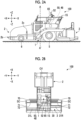
- Figs. 2A and 2B show a configuration example of the asphalt finisher 100 as the road paving machine according to the present embodiment.
- Fig. 2A is a side view
- Fig. 2B is a top view.
- the asphalt finisher 100 is configured to mainly include the tractor 1, the hopper 2, and the screed 3.
- the tractor 1 is a mechanism for traveling the asphalt finisher 100, and tows the screed 3.
- the tractor 1 moves the asphalt finisher 100 by rotating rear wheels 5 by using a rear wheel traveling motor and rotating front wheels 6 by using a front wheel traveling motor.
- Both of the rear wheel traveling motor and the front wheel traveling motor are hydraulic motors that rotate by receiving supply of a hydraulic oil from a hydraulic pump.
- the tractor 1 may include a crawler instead of the wheels.
- a driver's seat 1S and an operation panel 65 are disposed at an upper portion of the tractor 1.
- the hopper 2 which is an example of the work device, is a mechanism for receiving a paving material (for example, an asphalt mixture).
- the hopper 2 is installed on the front side of the tractor 1, and is configured to be able to be opened and closed in a vehicle width direction by a hopper cylinder 2c.
- the asphalt finisher 100 usually receives the paving material that is discharged from the loading platform 201 of the dump truck 200 with the hopper 2 in a fully open state. In addition, the asphalt finisher 100 can continue to travel while pushing the dump truck 200 forward through a push roller 2b even when receiving the paving material that is discharged from the loading platform 201 of the dump truck 200.
- the hopper 2 is closed, and the paving material near the inner wall of the hopper 2 is collected to the center portion of the hopper 2, so that the paving material can be fed to the screw SC present on the rear side by a conveyor CV, which is an example of the work device.
- the paving material fed to the rear side of the tractor 1 is spread in the vehicle width direction on the rear side of the tractor 1 and the front side of the screed 3 by a screw SC.
- the screw SC is in a state where extension screws are connected right and left.
- the screed 3 is a mechanism provided at a rear portion of the tractor 1 and for leveling the paving material spread by the screw SC.
- the screed 3 is configured to be able to be lifted and lowered (moved) in the vertical direction (up-down direction) and to be able to expand and contract in the vehicle width direction by a hydraulic cylinder.
- the width of the screed 3 is larger than the width of the tractor 1.
- the screed 3 includes a main screed 30, a left expansion and contraction screed 31L, and a right expansion and contraction screed 31R.
- the left expansion and contraction screed 31L and the right expansion and contraction screed 31R are configured to be able to expand and contract in the vehicle width direction (Y-axis direction). Then, the left expansion and contraction screed 31L and the right expansion and contraction screed 31R that are capable of expanding and contracting in the vehicle width direction are disposed to be offset from each other in an advancing direction (X-axis direction). Therefore, the screed 3 can have a width (length in the vehicle width direction) longer than the width when not offset, and the width can be extended longer in the vehicle width direction, so that a wider newly constructed pavement body can be constructed.
- a controller 50 is a control unit that controls the asphalt finisher 100.
- the controller 50 is, for example, a computer that includes a CPU, a volatile memory, a non-volatile memory, and the like.
- the controller 50 is a computer that includes a CPU and a RAM, and is mounted on the tractor 1.
- Various functions of the controller 50 are realized, for example, by executing a program stored in an auxiliary storage device by the CPU.
- the auxiliary storage device is a device for storing various types of information.
- the auxiliary storage device is a non-volatile memory and is integrated with the controller 50.
- the auxiliary storage device may be disposed outside the controller 50 as a structure different from the controller 50.
- a display unit 52 is a device for displaying various types of information.
- the display unit 52 is a liquid crystal display installed on the operation panel 65, and displays various images that are output by the controller 50.
- a retaining plate 70 is a plate-shaped member for preventing a paving material sent out in the vehicle width direction by the screw SC from being scattered in front of the screw SC in order to appropriately send out the paving material in the vehicle width direction by the screw SC.
- a side plate 71 is also attached to the distal end of a mold board 72.
- the mold board 72 is a member for adjusting the amount of the paving material that stays in front of the left expansion and contraction screed 31L and the right expansion and contraction screed 31R, of the paving material spread by the screw SC, and is configured to be able to expand and contract in the vehicle width direction together with the left expansion and contraction screed 31L and the right expansion and contraction screed 31R.
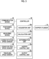
- Fig. 3 is a block diagram showing a configuration example of the controller 50 of the asphalt finisher 100 according to the present embodiment and the equipment connected to the controller 50.
- a communication device 42 performs wireless communication with a device that is present in the periphery of the asphalt finisher 100, a server that manages a work site, or the like.
- a wireless communication standard of the communication device 42 for example, any one or more of Wi-Fi (registered trademark), wireless LAN, Bluetooth (registered trademark), and the like may be used.
- a positioning device 43 is configured to be able to detect the position of the asphalt finisher 100.
- the positioning device 43 is a GNSS receiver.
- the position of the asphalt finisher 100 is expressed using a reference coordinate system. That is, the position of the asphalt finisher 100 is specified by the coordinates in the reference coordinate system.
- the reference coordinate system is, for example, a world geodetic coordinate system.
- the world geodetic coordinate system is a three-dimensional orthogonal XYZ coordinate system in which the origin is at the center of gravity of the earth, the X-axis is in a direction of an intersection point of the Greenwich meridian and the equator, the Y-axis is in a direction of 90 degrees east longitude, and the Z-axis is in a direction of the North Pole.
- a measuring device 44 is, for example, an ultrasonic sensor, a monocular camera, a stereo camera, a LIDAR, or the like.
- the measuring device 44 measures a distance to a roadbed before the paving material is spread and a distance to a road surface (surface of the paving material) leveled with the screed 3, and outputs a difference between the measured distances to the controller 50 as the thickness of the paving material.
- a screw rotation speed sensor 45 is configured to detect the rotation speed of the screw SC.
- the screw rotation speed sensor 45 is an encoder that detects the angular velocity of a rotary shaft of a hydraulic motor that drives the screw SC.
- the screw rotation speed sensor 45 may be configured with a proximity switch or the like, which detects a slit formed in a rotating plate.
- a conveyor feed speed sensor 46 is configured to detect the feed speed of the conveyor CV.
- the conveyor feed speed sensor 46 is an encoder that detects the angular velocity of a rotary shaft of a hydraulic motor that drives the conveyor CV.
- the conveyor feed speed sensor 46 may be configured with a proximity switch or the like, which detects a slit formed in a rotating plate.
- a traveling speed sensor 47 is configured to detect a traveling speed of the asphalt finisher 100.
- the traveling speed sensor 47 is an encoder that detects the angular velocity of a rotary shaft of the rear wheel traveling motor that drives the rear wheels 5 of the tractor 1.
- the traveling speed sensor 47 may be configured with a proximity switch or the like, which detects a slit formed in a rotating plate.
- the hopper cylinder 2c is configured to open and close the hopper 2 in the vehicle width direction.
- Fig. 4 is an explanatory diagram showing an opening and closing operation of the hopper 2 according to the present embodiment.
- a hopper 2a As shown in Fig. 4 , in the hopper 2, each of an accommodation unit 2a, the hopper cylinder 2c, and an opening and closing pivot shaft 2d is formed symmetrically. Then, two conveyors CV are extended between the accommodation units 2a provided symmetrically.
- the accommodation unit 2a of the hopper 2 is provided to be able to be opened and closed with the opening and closing pivot shaft 2d as a reference.
- the accommodation unit 2a is opened and closed by controlling the expansion and contraction of the hopper cylinder 2c.
- the expansion and contraction of the hopper cylinder 2c is controlled by the controller 50.
- the controller 50 includes an acquisition unit 50a, a calculation unit 50b, a determination unit 50c, a hopper control unit 50d, and an output control unit 50e, as functional blocks that are more specifically configured with software, hardware, or a combination thereof.
- the acquisition unit 50a acquires various types of information.
- the acquisition unit 50a acquires information received by the communication device 42 or detection information from various sensors.
- the acquisition unit 50a acquires information from an external device via the communication device 42. For example, the acquisition unit 50a acquires information indicating the amount of the paving material that is input into the hopper 2 from an external device via the communication device 42. For example, the acquisition unit 50a acquires the amount of the paving material loaded on the dump truck 200, which is received from the controller C3 of the plant 300 via the communication device T3, as the information indicating the amount of the paving material input from the dump truck 200 to the hopper 2.
- the amount of the paving material according to the present embodiment may be any reference for determining whether or not the paving material is loaded in the hopper 2, and may be, for example, the volume of the paving material or the weight of the paving material.
- the controller 50 may hold the density of the paving material or the like in advance, and calculate the weight from the volume or the volume from the weight, as necessary.
- the method for acquiring the information indicating the amount of the paving material is not limited to the reception from the controller C3 of the plant 300, and any method may be used.
- the loading amount of the paving material at the time of shipping is stated on a shipping ticket at the time of shipping of the dump truck 200. Therefore, the acquisition unit 50a may cause an imaging device (not shown) to read a shipping ticket (an example of a medium) of the dump truck 200, extract information indicating the loading amount of the paving material shown on the shipping ticket, and acquire the extracted information as the information indicating the amount of the paving material that is input into the hopper 2.
- the reading of the shipping ticket or the like may be performed by an external device (for example, a mobile communication terminal).
- any worker may input the loading amount of the paving material shown on the shipping ticket to an external device (for example, a mobile communication terminal). Then, the acquisition unit 50a may acquire, from the external device, information indicating the loading amount of the paving material as the information indicating the amount of the paving material that is input into the hopper 2.
- the target to be read is not limited to the shipping ticket, and for example, the maximum loading amount shown on a vehicle inspection certificate (an example of the medium) may be read as the loading amount of the paving material.
- a self-weight meter for detecting a loading weight may be provided in the dump truck 200. Therefore, the acquisition unit 50a may acquire, as the amount of the input paving material, the loading weight measured by the self-weight meter from the dump truck 200 via the communication device 42.
- the acquisition unit 50a may acquire a difference between the weight of the dump truck 200 measured by a weight measuring device before the paving material is discharged and the weight of the dump truck 200 measured by the weight measuring device after the paving material is discharged, as the information indicating the amount of the paving material that is input from the dump truck 200 to the hopper 2.
- the weight measuring device of the dump truck 200 may be disposed on a route from the plant 300 to the asphalt finisher 100.
- the acquisition unit 50a may receive the amount of the paving material loaded on the dump truck 200 from an external device capable of communicating with a fixed-point imaging device provided at a work site.
- the external device may be a monitoring device that monitors the work site, and may estimate the amount of the paving material loaded on the loading platform 201 of the dump truck 200 shown in an image, based on image information captured by the fixed-point imaging device installed at the work site, and transmit the estimated amount of the paving material to the asphalt finisher 100.
- the acquisition unit 50a can acquire the amount of the paving material input into the hopper 2 without providing a detection device or the like for detection in the asphalt finisher 100, by acquiring the amount of the paving material with the method described above. Therefore, it is possible to reduce costs because there is no need to provide a detection device or the like, and it is possible to acquire the amount of the paving material input into the hopper 2 even in a case where a change occurs in the peripheral situation such that the detection device cannot be used. Therefore, the controller 50 according to the present embodiment can improve the accuracy of the opening and closing control of the hopper 2, based on the amount of the input paving material.
- the acquisition unit 50a acquires information indicating the amount (first amount) of the paving material input into the hopper 2, based on the input operation through the operation panel 65 by the operator or the communication from the external device. In this manner, in the present embodiment, since it is not necessary to provide a detection device or the like for measuring the amount of the paving material input into the hopper 2, it is possible to reduce costs.
- the acquisition unit 50a acquires a timing when the paving material is input from the dump truck 200.
- the timing when the paving material is input from the dump truck 200 may be acquired from the input operation through the operation panel 65 by the operator.
- the acquisition unit 50a may acquire a timing when the dump truck 200 lifts the loading platform 201.
- the timing when the dump truck 200 lifts the loading platform 201 may be received from the dump truck 200 via the communication device 42, or may be received from a monitoring device (not shown) that monitors the operation of the dump truck 200. In this way, the acquisition unit 50a can acquire the amount of the paving material input from the dump truck 200 and the timing when the paving material is input from the dump truck 200.
- the acquisition unit 50a acquires position information of the asphalt finisher 100 from the positioning device 43.
- the acquisition unit 50a acquires information indicating the thickness of the paving material in the vertical direction (Z-axis direction) from the measuring device 44.
- the acquisition unit 50a acquires rotation speed information of the screw SC from the screw rotation speed sensor 45.
- the acquisition unit 50a acquires conveyance speed information of the conveyor CV from the conveyor feed speed sensor 46.
- the acquisition unit 50a acquires speed information of the asphalt finisher 100 detected by the traveling speed sensor 47. In addition, the acquisition unit 50a acquires steering angle information from the tractor 1.
- the calculation unit 50b calculates the amount (an example of a second amount) of the paving material conveyed from the hopper 2 from the detection result of the detection device.
- the calculation unit 50b calculates the amount of the paving material conveyed from the hopper 2, based on the conveyance speed information of the paving material acquired from the conveyor feed speed sensor 46 and the area of the opening portion of the conveyor CV.
- Fig. 5 is a diagram showing the opening portion of the conveyor CV of the asphalt finisher 100 according to the present embodiment.
- Fig. 5 shows an example in which a cross section along line A-A' of the asphalt finisher 100 shown in Fig. 2A is referenced in the +X-axis direction.
- opening portions 401 and 402 are provided to correspond to the two conveyors CV, respectively.
- Each of the opening portions 401 and 402 has a width Wc and a height H.
- the conveyor CV conveys the paving material to the screed 3 through each of the opening portions 401 and 402 shown in Fig. 5 .
- the calculation unit 50b calculates the amount of the paving material conveyed from the hopper 2, based on the area (an example of the opening area) of each of the opening portions 401 and 402 and a conveyance speed Vc of the conveyor CV. Specifically, the calculation unit 50b calculates an amount Q of the paving material conveyed from the hopper 2 for each of the opening portions 401 and 402 by using Expression (1) below.
- a correction coefficient ⁇ a is determined according to the proportion of the paving material present in each of the opening portions 401 and 402 of the conveyors CV and the density or the like of the paving material.
- the controller 50 can improve the accuracy of the opening and closing control of the hopper 2, based on the amount of the paving material carried out for each of the opening portions 401 and 402.
- Q ⁇ Vc ⁇ Wc ⁇ H ⁇ ⁇ a dt
- the present embodiment is not limited to the method of calculating the amount of the paving material conveyed from the hopper 2, based on the conveyance speed of the paving material acquired from the conveyor feed speed sensor 46 and the area of the opening portion of the conveyor CV. Therefore, another method of calculating the amount of the paving material conveyed from another hopper 2 will be described.
- the calculation unit 50b may calculate the amount of the paving material conveyed from the hopper, based on the rotation speed of the screw SC for spreading the paving material and the shape of the screw SC (for example, the projected area of the screw SC and the screw pitch of the screw SC).
- a rotation speed Nsc of the screw SC is shown in the rotation speed information acquired from the screw rotation speed sensor 45.
- a projected area (a projected area of a screw diameter (of a portion of a blade for feeding the paving material)) Ap and a screw pitch P of the screw SC are determined in advance.
- the calculation unit 50b calculates the amount (for example, weight) Q of the paving material conveyed from the hopper 2 by using Expression (2) below.
- a correction coefficient ⁇ b is determined in accordance with a correspondence relationship between the rotation frequency of the screw SC and the amount of the paving material spread from the screw SC.
- the controller 50 can improve the accuracy of the opening and closing control of the hopper 2 based on the amount of the paving material carried out.
- Q ⁇ Ap ⁇ P ⁇ Nsc ⁇ ⁇ b dt
- the calculation unit 50b may calculate the amount Q of the paving material conveyed from the hopper 2, based on an area S of the road surface leveled with the screed 3 and a thickness th of the paving material spread on the road surface. Specifically, the calculation unit 50b calculates the amount Q of the paving material conveyed from the hopper 2 by multiplying the area S of the road surface, the thickness th of the road surface, and a correction coefficient ⁇ c. The thickness th of the paving material is based on the thickness of the paving material in the vertical direction (Z-axis direction) measured by the measuring device 44.
- the area S of the road surface is calculated based on a road surface width W at which the asphalt finisher 100 performs the work, a movement speed V of the asphalt finisher 100, a movement time T of the asphalt finisher 100, and a steering angle of the asphalt finisher 100, in other words, the degree of bending of the road surface.
- a method of calculating the area of the road surface based on these pieces of information may be a known method, and thus description thereof will be omitted.
- the road surface width W may be acquired from construction information, or may be the width of the screed 3.
- the correction coefficient ⁇ c is determined in accordance with the proportion of the paving material per unit volume of the road surface, and the density or the like of the paving material. Furthermore, the correction coefficient ⁇ c may be adjusted in consideration of the degree of bending of the road surface and further in consideration of acceleration or deceleration or the like corresponding to the curvature radius when the asphalt finisher 100 bends.
- the movement speed V of the asphalt finisher 100 is based on speed information acquired from the traveling speed sensor 47.
- the method of acquiring the movement speed V of the asphalt finisher 100 is not limited to the speed information acquired from the traveling speed sensor 47, and for example, the movement speed of the asphalt finisher 100 may be derived based on the wheel speed of the front wheel 6.
- the movement distance per unit time of the asphalt finisher 100 may be derived based on a change in position per unit time of the asphalt finisher 100 indicated by the position information acquired from the positioning device 43.
- the controller 50 can improve the accuracy of the opening and closing control of the hopper 2 based on the amount of the paving material carried out.
- the calculation unit 50b further calculates the amount of the paving material loaded in the hopper 2, based on the amount of the paving material input into the hopper 2 acquired by the acquisition unit 50a and the amount Q of the paving material conveyed from the hopper 2.
- the determination unit 50c determines the amount of the paving material loaded in the hopper 2.
- the hopper control unit 50d performs the opening and closing control of the hopper 2, based on the determination result of the determination unit 50c based on the amount of the input paving material and the amount of the conveyed paving material. Specifically, the hopper control unit 50d outputs a control command for expanding and contracting the hopper cylinder 2c in order to perform the opening and closing control of the hopper 2.
- the determination unit 50c determines whether or not the amount (for example, weight or volume) of the paving material loaded in the hopper 2 is equal to or less than a first threshold. In a case where it is determined that the amount of the paving material loaded in the hopper 2 is larger than the first threshold, the hopper control unit 50d does not particularly perform the opening and closing control of the hopper 2.
- the determination unit 50c determines whether or not the amount of the paving material loaded in the hopper 2 is equal to or less than a second threshold (second threshold ⁇ first threshold). In a case where it is determined that the amount of the paving material loaded in the hopper 2 is larger than the second threshold and smaller than the first threshold, the hopper control unit 50d continues the control to gradually close the hopper 2.
- the hopper control unit 50d repeats the control to open the hopper 2 and the control to close the hopper 2.
- the hopper control unit 50d repeatedly performs the control to open the hopper 2 and the control to close the hopper 2, whereby the paving material adhered to the accommodation unit 2a of the hopper 2 is dropped to the conveyor CV.
- the hopper control unit 50d performs the control to open the hopper 2. In this way, the paving material can be discharged from the dump truck 200.
- the control to open the hopper 2 may be based on an operation by the operator, or may be based on the detection result of the proximity of the dump truck 200 by the detection device provided in the asphalt finisher 100.
- the output control unit 50e outputs information about the amount of the paving material loaded in the hopper 2, which is calculated based on the amount of the paving material input into the hopper 2 and the amount Q of the paving material conveyed from the hopper 2, to the display unit 52.
- the information about the amount (remaining amount) of the paving material loaded in the hopper 2 may be any aspect, and may be, for example, the weight of the paving material or the volume of the paving material loaded in the hopper 2.
- the output control unit 50e may output a numerical value (for example, %) or an indicator indicating the amount of the paving material currently loaded in the hopper 2 with respect to the amount of the paving material that can be loaded in the hopper 2 to the display unit 52.
- the output control unit 50e does not limit the output destination of the information about the amount of the paving material loaded in the hopper 2 to the display unit 52.
- the output control unit 50e may output the information about the amount of the paving material loaded in the hopper 2 to an external device.
- FIG. 6 is a flowchart showing the processing procedure that is executed by the controller 50 according to the present embodiment.
- the acquisition unit 50a acquires the amount of the paving material input from the dump truck 200 to the hopper 2 (S1501).
- a method of acquiring the amount of the paving material input into the hopper 2 uses the method described above, and thus the description thereof will be omitted.
- the acquisition unit 50a acquires detection information for calculating the amount of the paving material conveyed from the hopper 2 from the detection device (S1502).
- the calculation unit 50b calculates the amount of the paving material conveyed from the hopper 2 from the detection result of the detection device (S1503).
- the calculation unit 50b calculates the amount of the paving material loaded in the hopper 2, based on the amount of the paving material input into the hopper 2 and the amount of the paving material conveyed from the hopper 2 (S1504).
- the determination unit 50c determines whether or not the amount of the loaded paving material is equal to or less than the second threshold (S1505). In a case where the determination unit 50c determines that the amount of the loaded paving material is equal to or less than the second threshold (S1505: YES), the hopper control unit 50d performs control to repeat the opening and closing of the hopper 2 (S1506). After a predetermined time has elapsed, the processing proceeds to S1509.
- the determination unit 50c determines whether or not the amount of the loaded paving material is equal to or less than the first threshold (S1507).
- the hopper control unit 50d performs the control to gradually close the hopper 2 (S1508). Then, after a predetermined time has elapsed, the processing proceeds to S1509.
- the speed at which the hopper 2 is closed is adjusted according to the embodiment, such as the conveyance speed of the conveyor CV.
- control is not particularly performed.
- the determination unit 50c determines whether or not the dump truck 200 is in proximity to the asphalt finisher 100 (S1509).
- the determination may be an input operation by the operator indicating that the dump truck 200 is in proximity, or may be the detection result of the detection device provided in the asphalt finisher 100.
- the hopper control unit 50d performs the control to open the hopper 2 (S1510).
- the determination unit 50c determines whether or not the paving material is input from the dump truck 200 (S1511). The determination is based on the timing when the paving material is input from the dump truck 200 acquired by the acquisition unit 50a. For example, the determination may be performed based on whether or not the notification that the loading platform 201 is lifted is received from the dump truck 200 or the monitoring device, or may be based on whether or not an input operation to input the paving material is performed by the operator through the operation panel 65.
- the processing is performed from S1502.
- the processing is performed from S1501. That is, the subsequent processing is performed based on the amount of the paving material newly acquired by the acquisition unit 50a and received or input from the external device.
- the acquisition unit 50a may add the amount of the paving material loaded in the hopper to the amount of the paving material received from the external device or input by the operation. In this way, since the amount of the paving material is updated at the timing when the paving material is input from the dump truck 200, it is possible to improve the calculation accuracy of the amount of the paving material loaded in the hopper 2.
- the opening and closing control of the hopper 2 of the present embodiment is an example, and is not limited to the opening and closing control described above.
- the controller 50 may perform only one of the control to gradually close the hopper 2 and the control to repeat the opening and the closing in a case where the amount of the paving material loaded in the hopper 2 is equal to or less than a predetermined threshold, or may perform other control. That is, it is only necessary to perform the opening and closing control of the hopper 2 in accordance with the amount of the paving material loaded in the hopper 2.
- the embodiment described above has been described with respect to a case of using the correction coefficient corresponding to a calculation pattern.
- the embodiment described above is not limited to the method of using the correction coefficient corresponding to the calculation pattern, and the correction coefficient may be a coefficient obtained by considering a situation when the asphalt finisher 100 performs construction, in addition to the calculation pattern. Therefore, in the present modification example, a case of using a correction coefficient obtained by considering a situation when the asphalt finisher 100 performs construction will be described.
- any calculation pattern among the calculation patterns of the amount Q of the paving material shown in the embodiment described above may be used.
- the correction coefficient according to the present modification example may be adjusted according to the weather, the humidity, the air temperature, the road surface situation, the type of a composite material contained in the paving material, or the like when the asphalt finisher 100 performs the construction.
- any method may be used, and for example, a function determined in advance may be used.
- a function determined in advance may be used.
- a case of using a trained model will be described.
- a learning device for performing machine learning may be provided as the construction management system SYS.
- the learning device may be, for example, an on-premises server installed in the plant 300 or a remote monitoring area, or may be a cloud service.
- the learning device generates a trained model by performing machine learning by using, as teaching data, a current situation based on any one or more of weather, humidity, air temperature, a road surface situation, and the type of a composite material contained in the paving material, and a correction coefficient corresponding to the current situation.
- a current situation based on any one or more of weather, humidity, air temperature, a road surface situation, and the type of a composite material contained in the paving material, and a correction coefficient corresponding to the current situation.
- application of, for example, deep learning can be considered.
- a method of performing learning using a neural network and backpropagation may be considered. However, other methods may be used.
- the trained model outputs a correction coefficient corresponding to the current situation in a case where information indicating the current situation based on any one or more of the weather, the humidity, the air temperature, the road surface situation, and the type of a composite material contained in the paving material is input.
- the information indicating the current situation may be input by the operator or may be received from an external device through the communication device 42.
- the learning device outputs the trained model to the asphalt finisher 100.
- the output method may be any aspect, and for example, the output method may be transmission via a public network, or may be stored in an auxiliary storage device 48 via a detachable non-volatile memory.
- the trained model is stored in the auxiliary storage device 48 of the asphalt finisher 100.
- the calculation unit 50b of the asphalt finisher 100 of the present modification example acquires the correction coefficient by inputting the current situation to the trained model stored in the auxiliary storage device 48.
- the calculation of the amount Q of the paving material using the correction coefficient is the same as that in the embodiment described above, and thus description thereof will be omitted.
- the trained model is used to specify the correction coefficient, so that the accuracy in calculating the amount Q of the paving material can be improved.
- the amount of the paving material loaded in the hopper is calculated by another method other than the method of recognizing the image, and the opening and closing control of the hopper is performed according to the amount of the paving material loaded in the hopper. Therefore, a processing burden can be reduced by suppressing the recognition of the image or the like in order to perform the opening and closing control of the hopper. Furthermore, since a processing burden is reduced, it is not necessary to mount a high-cost calculation device, and thus it is possible to reduce costs.
- the controller 50 since the amount of the loaded paving material can be calculated regardless of a change in the surrounding situation, the opening and closing control of the hopper can be performed at an appropriate timing. Therefore, it is possible to improve work efficiency.
Landscapes
- Engineering & Computer Science (AREA)
- Architecture (AREA)
- Civil Engineering (AREA)
- Structural Engineering (AREA)
- Road Paving Machines (AREA)
Applications Claiming Priority (1)
| Application Number | Priority Date | Filing Date | Title |
|---|---|---|---|
| JP2023146387A JP2025039344A (ja) | 2023-09-08 | 2023-09-08 | アスファルトフィニッシャ |
Publications (1)
| Publication Number | Publication Date |
|---|---|
| EP4520868A1 true EP4520868A1 (fr) | 2025-03-12 |
Family
ID=92633885
Family Applications (1)
| Application Number | Title | Priority Date | Filing Date |
|---|---|---|---|
| EP24197863.4A Pending EP4520868A1 (fr) | 2023-09-08 | 2024-09-02 | Finisseur d'asphalte |
Country Status (3)
| Country | Link |
|---|---|
| EP (1) | EP4520868A1 (fr) |
| JP (1) | JP2025039344A (fr) |
| CN (1) | CN119593275A (fr) |
Citations (3)
| Publication number | Priority date | Publication date | Assignee | Title |
|---|---|---|---|---|
| JP2020139372A (ja) | 2019-03-01 | 2020-09-03 | 範多機械株式会社 | 道路舗装機械及びそれに用いられるホッパ制御装置 |
| WO2021193381A1 (fr) * | 2020-03-27 | 2021-09-30 | 住友建機株式会社 | Épandeuse automatique d'enrobé et dispositif d'apprentissage machine |
| EP4119726A1 (fr) * | 2020-03-11 | 2023-01-18 | Sumitomo Construction Machinery Co., Ltd. | Système de gestion de construction et finisseur d'asphalte |
-
2023
- 2023-09-08 JP JP2023146387A patent/JP2025039344A/ja active Pending
-
2024
- 2024-07-15 CN CN202410942315.1A patent/CN119593275A/zh active Pending
- 2024-09-02 EP EP24197863.4A patent/EP4520868A1/fr active Pending
Patent Citations (3)
| Publication number | Priority date | Publication date | Assignee | Title |
|---|---|---|---|---|
| JP2020139372A (ja) | 2019-03-01 | 2020-09-03 | 範多機械株式会社 | 道路舗装機械及びそれに用いられるホッパ制御装置 |
| EP4119726A1 (fr) * | 2020-03-11 | 2023-01-18 | Sumitomo Construction Machinery Co., Ltd. | Système de gestion de construction et finisseur d'asphalte |
| WO2021193381A1 (fr) * | 2020-03-27 | 2021-09-30 | 住友建機株式会社 | Épandeuse automatique d'enrobé et dispositif d'apprentissage machine |
Also Published As
| Publication number | Publication date |
|---|---|
| JP2025039344A (ja) | 2025-03-21 |
| CN119593275A (zh) | 2025-03-11 |
Similar Documents
| Publication | Publication Date | Title |
|---|---|---|
| US10949786B2 (en) | Cold planer material transport management system | |
| CN108350669B (zh) | 用于铣削操作的卡车位置控制系统 | |
| US9766637B2 (en) | Operation control system for mining machine and operation control method for mining machine | |
| KR102023480B1 (ko) | 덤프 트럭 | |
| US9008889B2 (en) | Method of controlling travel within travel system for unmanned vehicle and travel system for unmanned vehicle | |
| JP2022079773A (ja) | 作業システムおよび制御方法 | |
| JP2020023869A (ja) | 重量センサを有するベルトコンベヤシステムを有する建設機械 | |
| US12084833B2 (en) | Construction machine management system, construction machine management program, construction machine management method, construction machine, and external management device for construction machine | |
| CN113743793B (zh) | 一种露天矿排土场卡车卸载调度方法及系统 | |
| JP6757749B2 (ja) | 作業機械の管理システム、作業機械、作業機械の管理方法 | |
| EP4130383A1 (fr) | Dispositif de finition d'asphalte | |
| EP4265842A1 (fr) | Engin de chantier et procédé de commande d'un engin de chantier | |
| CN113463719A (zh) | 装载机自主作业控制系统和方法 | |
| US20100250123A1 (en) | Method and system for dispensing material from machines | |
| CN116065460A (zh) | 跟踪机器周围的环境以定义实际切割轮廓 | |
| US12039866B2 (en) | Display unit for road machine | |
| EP4520868A1 (fr) | Finisseur d'asphalte | |
| JP3018275B2 (ja) | 土木用敷均し装置 | |
| KR20230003025A (ko) | 작업 시스템 및 제어 방법 | |
| EP4317587A1 (fr) | Finisseuse d'asphalte et système de pavage de surface de roulement | |
| JP7074548B2 (ja) | 撒き出し制御方法 | |
| CN103147379B (zh) | 对铣刨机投料角度进行控制的方法、设备、系统及铣刨机 | |
| CN114514352B (zh) | 用于摊铺机的定位系统 | |
| EP4579039A1 (fr) | Machine de pavage de route et système de gestion | |
| EP4372147A1 (fr) | Finisseur d'asphalte |
Legal Events
| Date | Code | Title | Description |
|---|---|---|---|
| PUAI | Public reference made under article 153(3) epc to a published international application that has entered the european phase |
Free format text: ORIGINAL CODE: 0009012 |
|
| STAA | Information on the status of an ep patent application or granted ep patent |
Free format text: STATUS: EXAMINATION IS IN PROGRESS |
|
| 17P | Request for examination filed |
Effective date: 20240902 |
|
| AK | Designated contracting states |
Kind code of ref document: A1 Designated state(s): AL AT BE BG CH CY CZ DE DK EE ES FI FR GB GR HR HU IE IS IT LI LT LU LV MC ME MK MT NL NO PL PT RO RS SE SI SK SM TR |