EP4520896A1 - Führungsvorrichtung zur montage eines turmfasss und montageverfahren dafür - Google Patents
Führungsvorrichtung zur montage eines turmfasss und montageverfahren dafür Download PDFInfo
- Publication number
- EP4520896A1 EP4520896A1 EP23306503.6A EP23306503A EP4520896A1 EP 4520896 A1 EP4520896 A1 EP 4520896A1 EP 23306503 A EP23306503 A EP 23306503A EP 4520896 A1 EP4520896 A1 EP 4520896A1
- Authority
- EP
- European Patent Office
- Prior art keywords
- guide element
- male
- support base
- pylon
- female
- Prior art date
- Legal status (The legal status is an assumption and is not a legal conclusion. Google has not performed a legal analysis and makes no representation as to the accuracy of the status listed.)
- Granted
Links
Images




Classifications
-
- E—FIXED CONSTRUCTIONS
- E04—BUILDING
- E04H—BUILDINGS OR LIKE STRUCTURES FOR PARTICULAR PURPOSES; SWIMMING OR SPLASH BATHS OR POOLS; MASTS; FENCING; TENTS OR CANOPIES, IN GENERAL
- E04H12/00—Towers; Masts or poles; Chimney stacks; Water-towers; Methods of erecting such structures
- E04H12/02—Structures made of specified materials
- E04H12/08—Structures made of specified materials of metal
- E04H12/085—Details of flanges for tubular masts
-
- E—FIXED CONSTRUCTIONS
- E02—HYDRAULIC ENGINEERING; FOUNDATIONS; SOIL SHIFTING
- E02D—FOUNDATIONS; EXCAVATIONS; EMBANKMENTS; UNDERGROUND OR UNDERWATER STRUCTURES
- E02D13/00—Accessories for placing or removing piles or bulkheads, e.g. noise attenuating chambers
- E02D13/04—Guide devices; Guide frames
-
- E—FIXED CONSTRUCTIONS
- E02—HYDRAULIC ENGINEERING; FOUNDATIONS; SOIL SHIFTING
- E02D—FOUNDATIONS; EXCAVATIONS; EMBANKMENTS; UNDERGROUND OR UNDERWATER STRUCTURES
- E02D27/00—Foundations as substructures
- E02D27/32—Foundations for special purposes
- E02D27/42—Foundations for poles, masts or chimneys
- E02D27/425—Foundations for poles, masts or chimneys specially adapted for wind motors masts
-
- E—FIXED CONSTRUCTIONS
- E04—BUILDING
- E04H—BUILDINGS OR LIKE STRUCTURES FOR PARTICULAR PURPOSES; SWIMMING OR SPLASH BATHS OR POOLS; MASTS; FENCING; TENTS OR CANOPIES, IN GENERAL
- E04H12/00—Towers; Masts or poles; Chimney stacks; Water-towers; Methods of erecting such structures
- E04H12/22—Sockets or holders for poles or posts
- E04H12/2253—Mounting poles or posts to the holder
-
- E—FIXED CONSTRUCTIONS
- E04—BUILDING
- E04H—BUILDINGS OR LIKE STRUCTURES FOR PARTICULAR PURPOSES; SWIMMING OR SPLASH BATHS OR POOLS; MASTS; FENCING; TENTS OR CANOPIES, IN GENERAL
- E04H12/00—Towers; Masts or poles; Chimney stacks; Water-towers; Methods of erecting such structures
- E04H12/34—Arrangements for erecting or lowering towers, masts, poles, chimney stacks, or the like
- E04H12/342—Arrangements for stacking tower sections on top of each other
-
- F—MECHANICAL ENGINEERING; LIGHTING; HEATING; WEAPONS; BLASTING
- F03—MACHINES OR ENGINES FOR LIQUIDS; WIND, SPRING, OR WEIGHT MOTORS; PRODUCING MECHANICAL POWER OR A REACTIVE PROPULSIVE THRUST, NOT OTHERWISE PROVIDED FOR
- F03D—WIND MOTORS
- F03D13/00—Assembly, mounting or commissioning of wind motors; Arrangements specially adapted for transporting wind motor components
- F03D13/20—Arrangements for mounting or supporting wind motors; Masts or towers for wind motors
- F03D13/201—Towers
- F03D13/205—Connection means, e.g. joints between segments
- F03D13/206—Connection means, e.g. joints between segments between the tower and the foundation
-
- F—MECHANICAL ENGINEERING; LIGHTING; HEATING; WEAPONS; BLASTING
- F05—INDEXING SCHEMES RELATING TO ENGINES OR PUMPS IN VARIOUS SUBCLASSES OF CLASSES F01-F04
- F05B—INDEXING SCHEME RELATING TO WIND, SPRING, WEIGHT, INERTIA OR LIKE MOTORS, TO MACHINES OR ENGINES FOR LIQUIDS COVERED BY SUBCLASSES F03B, F03D AND F03G
- F05B2230/00—Manufacture
- F05B2230/60—Assembly methods
- F05B2230/604—Assembly methods using positioning or alignment devices for aligning or centering, e.g. pins
-
- F—MECHANICAL ENGINEERING; LIGHTING; HEATING; WEAPONS; BLASTING
- F05—INDEXING SCHEMES RELATING TO ENGINES OR PUMPS IN VARIOUS SUBCLASSES OF CLASSES F01-F04
- F05B—INDEXING SCHEME RELATING TO WIND, SPRING, WEIGHT, INERTIA OR LIKE MOTORS, TO MACHINES OR ENGINES FOR LIQUIDS COVERED BY SUBCLASSES F03B, F03D AND F03G
- F05B2260/00—Function
- F05B2260/30—Retaining components in desired mutual position
- F05B2260/301—Retaining bolts or nuts
Definitions
- the present invention relates to a guiding device for assembling a pylon shaft on a support base arranged on the ground. It also relates to a method for assembling a pylon shaft on a support base arranged on the ground using such a guiding device.
- a device of this type is described in the patent document FR 2 395 940 . It is particularly strongly recommended when the pylon has dimensions and weight such that it must be erected by helicopter or crane in several sections. This is the case, for example, of a single-legged pylon for chairlifts, cable cars or the like as envisaged in the aforementioned document, but also of a pylon for the transport and/or distribution of high or very high voltage electric current.
- the trapezoidal-shaped male guide element is mounted on a circular plate fixed under a pylon head while the female guide element takes the form of a corresponding perforated circular plate fixed above the hollow upper end of the pylon shaft.
- fixing the lower end of the pylon shaft to a support base placed on the ground also generally requires centering and guiding an angular orientation to match the fixing elements by bolting, for example threaded rods extending vertically on the support base and corresponding holes formed in an annular flange of the lower end of the pylon shaft.
- bolting for example threaded rods extending vertically on the support base and corresponding holes formed in an annular flange of the lower end of the pylon shaft.
- the pylon shaft is usually approached and lowered by helicopter, while operators on the ground and close to the fixing location precisely guide its angular and vertical orientation so that the holes in its annular flange are correctly aligned with the vertical threaded rods of the support base before the final descent phase allowing it to be placed on the ground.
- This operation is dangerous for the operators because they must remain as close as possible to the threaded rods to ensure their insertion into the holes in the annular flange of the pylon shaft without damaging them.
- the configuration of the female guide element in the document FR 2 395 940 makes it particularly vulnerable during the approach phase of the male element, the latter being likely to damage it as well as the fixing elements.
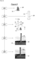
- the guide device is specifically designed to assist in the assembly of the pylon shaft on its support base.
- the fact of arranging the female guide element in the interior volume rather than by affixing a plate against one end of the pylon shaft limits the risk of its damage and allows it to be separated from the fixing elements, which also reduces the risk of damaging them during the approach phase of the male guide element.
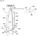
- the male guide element is generally triangular or pyramidal or rounded in shape at least in the vicinity of its free apex and comprises at least two distant reinforcements at its base meeting at the free apex.
- the male guide element further comprises a reinforcing plate, of generally triangular shape at least in the vicinity of its free apex, extending between two of said at least two reinforcements from the base in a plane orthogonal to a plane in which these two of said at least two reinforcements extend.
- the reinforcement plate is rounded and welded to the two of said at least two reinforcements at the free top of the male element.
- the female element comprises a receiving plate with an oblong slot and brackets or angles for fixing this receiving plate inside the pylon shaft at a distance from its lower end of contact with the support base.
- the oblong slot of the receiving plate of the female element further comprises at least one notch, for example two diametrically opposed notches, for inserting at least one reinforcement, for example two diametrically opposed reinforcements, of the male guide element for reinforced guidance in angular orientation of the assembly.
- the female guide element further comprises a consolidation plate with an enlarged opening fixed inside the pylon shaft parallel to the receiving plate between the latter and the lower end of contact of the pylon shaft with the support base, this consolidation plate forming a median support for the protection and guide ramps.
- protective caps for the threaded rods fixing the pylon shaft to the support base are also provided.
- the assembly of pylon shaft 10 and support base 12 shown schematically, in two arrangements respectively disassembled (that on the left) and assembled (that on the right), on the Figure 1 includes a guide device for carrying out the assembly.
- the pylon shaft 10 is cylindrical in shape, for example with a circular or polygonal cross-section, and has at its base a collared flange 14 for attachment to the support base 12. It is, for example, the shaft of a pylon for the transmission and/or distribution of high-voltage or very high-voltage electric current by air.
- This type of pylon may consist of several sections, the first of which, the pylon shaft, must be firmly anchored to the ground and at least the last of which, the pylon head, supports cables for the transmission and/or distribution of electric current, possibly using lateral brackets. It may also be a pylon shaft for supporting any other load, such as a set of chairlifts, cable cars or cable cars, etc.
- the support base 12 is generally essentially buried underground, for example in the form of an anchor cage cast in concrete, a plate of which upper plate 16 for fixing to the pylon shaft 10 appears on the ground surface in a horizontal plane.
- This upper plate 16 comprises a plurality of holes 18 arranged in a circle and respectively crossed by as many threaded rods 20 extending vertically upwards. These threaded rods 20 are for example extensions of the bars of the anchor cage.
- the collared flange 14 has as many holes 22 as the holes 18, arranged in correspondence with the latter for fixing the pylon shaft 10 to the support base 12 by bolting. Given the firm hold that must be ensured by this fixing, the clearance between the opening of the holes 22 and the external diameter of the threaded rods 20 is preferably very small.
- a guide device 24 comprising a male element 26 and a female element 28 according to a first embodiment of the invention.
- the male element 26 extends from a base 30 where it has a maximum width to a free top 32 of minimum width. It is provided with fixing means 34 designed to make it integral with the support base 12 by its base 30 from which it extends to its free top 32.
- its general shape is cruciform, from the cross-shaped base 30 to the free summit where four triangular fins meet, including two main fins 36 of greater width.
- the fixing means 34 are arranged on the lower face of the base 30 in contact with the upper plate 16, for example in the form of tapped holes allowing fixing by bolting.
- the female element 28 is intended to be secured to the pylon shaft 10. Whatever its structure and shape, for example a hollow plate, this female element 28 has a profiled centering slot 38 configured to receive the male guide element 26 by its free top 32.
- this slot 38 is oblong with two notches 40 at the diametrically opposite ends of its greatest width to receive the base of the two main fins 36 of the male guide element 26.
- the female guide element 28 is provided with fixing means 42 designed to arrange and fix it in the interior volume of the pylon shaft 10. It is also noted that it is independent of the collar flange 14.
- the fixing means 42 are shown very schematically on the Figure 1 because they can take any suitable form well known to those skilled in the art, in particular that of brackets or angles fixed to the internal wall of the pylon shaft 10 by welding and to the main body of the female guide element 28 by bolting.
- FIG. 3 schematically represents in perspective the general structure of the assembly of pylon shaft 10 and support base 12 according to the disassembled arrangement of the right part of the Figure 1 , in accordance with an alternative embodiment of the guidance device 24 including several optional elements.
- An additional rounding 90 orthogonal to its plane can also be formed by grinding in its thickness, that is to say between the two reinforcements 86 as illustrated in the right part of the Figure 5 , so as to further soften any contact between the male element 26 and the female element 28 during assembly.
Landscapes
- Engineering & Computer Science (AREA)
- Civil Engineering (AREA)
- Architecture (AREA)
- Structural Engineering (AREA)
- Life Sciences & Earth Sciences (AREA)
- General Engineering & Computer Science (AREA)
- Paleontology (AREA)
- Mining & Mineral Resources (AREA)
- General Life Sciences & Earth Sciences (AREA)
- Chemical & Material Sciences (AREA)
- Materials Engineering (AREA)
- Wood Science & Technology (AREA)
- Road Signs Or Road Markings (AREA)
- Refuge Islands, Traffic Blockers, Or Guard Fence (AREA)
Priority Applications (1)
| Application Number | Priority Date | Filing Date | Title |
|---|---|---|---|
| EP23306503.6A EP4520896B1 (de) | 2023-09-08 | 2023-09-08 | Führungsvorrichtung zur montage eines turmfasses und montageverfahren dafür |
Applications Claiming Priority (1)
| Application Number | Priority Date | Filing Date | Title |
|---|---|---|---|
| EP23306503.6A EP4520896B1 (de) | 2023-09-08 | 2023-09-08 | Führungsvorrichtung zur montage eines turmfasses und montageverfahren dafür |
Publications (3)
| Publication Number | Publication Date |
|---|---|
| EP4520896A1 true EP4520896A1 (de) | 2025-03-12 |
| EP4520896B1 EP4520896B1 (de) | 2026-02-11 |
| EP4520896C0 EP4520896C0 (de) | 2026-02-11 |
Family
ID=88287470
Family Applications (1)
| Application Number | Title | Priority Date | Filing Date |
|---|---|---|---|
| EP23306503.6A Active EP4520896B1 (de) | 2023-09-08 | 2023-09-08 | Führungsvorrichtung zur montage eines turmfasses und montageverfahren dafür |
Country Status (1)
| Country | Link |
|---|---|
| EP (1) | EP4520896B1 (de) |
Citations (3)
| Publication number | Priority date | Publication date | Assignee | Title |
|---|---|---|---|---|
| FR2395940A1 (fr) | 1977-06-30 | 1979-01-26 | Baudin Chateauneuf | Procede et dispositif pour l'assemblage de pylones de telesieges, de telecabines ou analogues, a l'aide d'helicoptere |
| KR100921258B1 (ko) * | 2008-12-11 | 2009-10-13 | 전명희 | 가로등 지주와 지지수단 결합구조 |
| CN109519029A (zh) * | 2018-11-20 | 2019-03-26 | 浙江盛达铁塔有限公司 | 直升机立塔定位装置 |
-
2023
- 2023-09-08 EP EP23306503.6A patent/EP4520896B1/de active Active
Patent Citations (3)
| Publication number | Priority date | Publication date | Assignee | Title |
|---|---|---|---|---|
| FR2395940A1 (fr) | 1977-06-30 | 1979-01-26 | Baudin Chateauneuf | Procede et dispositif pour l'assemblage de pylones de telesieges, de telecabines ou analogues, a l'aide d'helicoptere |
| KR100921258B1 (ko) * | 2008-12-11 | 2009-10-13 | 전명희 | 가로등 지주와 지지수단 결합구조 |
| CN109519029A (zh) * | 2018-11-20 | 2019-03-26 | 浙江盛达铁塔有限公司 | 直升机立塔定位装置 |
Also Published As
| Publication number | Publication date |
|---|---|
| EP4520896B1 (de) | 2026-02-11 |
| EP4520896C0 (de) | 2026-02-11 |
Similar Documents
| Publication | Publication Date | Title |
|---|---|---|
| EP2504249B1 (de) | Verschluss mit einer schwächungslinie | |
| EP3646425B1 (de) | Vorrichtung und verfahren zum greifen eines kabels mittels einer spannungsentlastungskabelklemme | |
| EP3609778B1 (de) | Schwimmer, insbesondere für eine offshore-windturbine | |
| EP2369097A1 (de) | Halterungseinheit für ein Dachelement und leichter Unterstand mit einer solchen Halterungseinheit | |
| EP0132205A1 (de) | Aufstellvorrichtung für Masten | |
| EP3720798B1 (de) | Vorrichtung zum aufwickeln eines schlauches | |
| EP4520896B1 (de) | Führungsvorrichtung zur montage eines turmfasses und montageverfahren dafür | |
| EP0326848B1 (de) | Verschluss zum Befestigen einer elektrischen Leitung an einem glockenförmigen Stützkörper und Werkzeug dafür | |
| FR2543481A1 (fr) | Dispositif d'ancrage dans le beton | |
| EP3645912B1 (de) | Vorrichtung und verfahren zur spannungsverriegelung eines kabels mittels kabelklemme | |
| FR2872843A1 (fr) | Procede de construction d'un mat longitudinal en beton, element tubulaire pour sa mise en oeuvre et mat obtenu | |
| FR2955135A1 (fr) | Mat articule extensible a charniere demontable | |
| FR2829777A1 (fr) | Dispositif d'ancrage au sol d'un objet | |
| EP1975337A1 (de) | Vorrichtung zum Halten der Enden zweier Schalungstafeln | |
| FR2683249A1 (fr) | Piquet pour cloture. | |
| EP3636839B1 (de) | Vorrichtung zum glätten einer säule | |
| EP1433501B1 (de) | Vorrichtung zur Befestigung eines Ankerpfostens an einer Tragstruktur | |
| EP2609265A1 (de) | Automatisierter zerlegbarer kippmast mit werkzeuglos montierbaren elementen | |
| EP1393777B1 (de) | Strebekopf | |
| EP4535585A1 (de) | Provisorische seitenkonsole für einen elektrischen mast und entsprechendes montageverfahren | |
| EP2549033B1 (de) | Modulare Struktur vom Typ Zirkuszelt oder Zelt | |
| EP2946814B1 (de) | Anordnung für die befestigung eines sportgeräts auf einem gestell, das mit einer reihe von lochrastungen ausgestattet ist, die mit einem befestigungsbügel zusammenwirken | |
| BE854225A (fr) | Carottier de sondage du type a cable | |
| CH357085A (fr) | Dispositif d'ancrage pour filet pare-avalanche | |
| FR2785932A1 (fr) | Support en beton ou similaire pour ligne electrique aerienne ou analogue |
Legal Events
| Date | Code | Title | Description |
|---|---|---|---|
| PUAI | Public reference made under article 153(3) epc to a published international application that has entered the european phase |
Free format text: ORIGINAL CODE: 0009012 |
|
| STAA | Information on the status of an ep patent application or granted ep patent |
Free format text: STATUS: THE APPLICATION HAS BEEN PUBLISHED |
|
| AK | Designated contracting states |
Kind code of ref document: A1 Designated state(s): AL AT BE BG CH CY CZ DE DK EE ES FI FR GB GR HR HU IE IS IT LI LT LU LV MC ME MK MT NL NO PL PT RO RS SE SI SK SM TR |
|
| STAA | Information on the status of an ep patent application or granted ep patent |
Free format text: STATUS: REQUEST FOR EXAMINATION WAS MADE |
|
| 17P | Request for examination filed |
Effective date: 20250320 |
|
| P01 | Opt-out of the competence of the unified patent court (upc) registered |
Free format text: CASE NUMBER: APP_12303/2025 Effective date: 20250313 |
|
| RAV | Requested validation state of the european patent: fee paid |
Extension state: TN Effective date: 20250320 Extension state: MA Effective date: 20250320 |
|
| GRAP | Despatch of communication of intention to grant a patent |
Free format text: ORIGINAL CODE: EPIDOSNIGR1 |
|
| STAA | Information on the status of an ep patent application or granted ep patent |
Free format text: STATUS: GRANT OF PATENT IS INTENDED |
|
| INTG | Intention to grant announced |
Effective date: 20250924 |
|
| GRAS | Grant fee paid |
Free format text: ORIGINAL CODE: EPIDOSNIGR3 |
|
| GRAA | (expected) grant |
Free format text: ORIGINAL CODE: 0009210 |
|
| STAA | Information on the status of an ep patent application or granted ep patent |
Free format text: STATUS: THE PATENT HAS BEEN GRANTED |
|
| AK | Designated contracting states |
Kind code of ref document: B1 Designated state(s): AL AT BE BG CH CY CZ DE DK EE ES FI FR GB GR HR HU IE IS IT LI LT LU LV MC ME MK MT NL NO PL PT RO RS SE SI SK SM TR |
|
| REG | Reference to a national code |
Ref country code: CH Ref legal event code: F10 Free format text: ST27 STATUS EVENT CODE: U-0-0-F10-F00 (AS PROVIDED BY THE NATIONAL OFFICE) Effective date: 20260211 Ref country code: GB Ref legal event code: FG4D Free format text: NOT ENGLISH |
|
| REG | Reference to a national code |
Ref country code: DE Ref legal event code: R096 Ref document number: 602023011877 Country of ref document: DE |
|
| REG | Reference to a national code |
Ref country code: IE Ref legal event code: FG4D Free format text: LANGUAGE OF EP DOCUMENT: FRENCH |
|
| U01 | Request for unitary effect filed |
Effective date: 20260310 |
|
| U07 | Unitary effect registered |
Designated state(s): AT BE BG DE DK EE FI FR IT LT LU LV MT NL PT RO SE SI Effective date: 20260316 |
|
| P04 | Withdrawal of opt-out of the competence of the unified patent court (upc) registered |
Free format text: CASE NUMBER: APP_12303_1/2025 Effective date: 20260316 |