EP4520914A1 - Système de forage à puissance pulsée avec transport de tube spiralé de puissance et de communication intégré - Google Patents
Système de forage à puissance pulsée avec transport de tube spiralé de puissance et de communication intégré Download PDFInfo
- Publication number
- EP4520914A1 EP4520914A1 EP24185757.2A EP24185757A EP4520914A1 EP 4520914 A1 EP4520914 A1 EP 4520914A1 EP 24185757 A EP24185757 A EP 24185757A EP 4520914 A1 EP4520914 A1 EP 4520914A1
- Authority
- EP
- European Patent Office
- Prior art keywords
- coiled tubing
- cable
- power
- tube
- fluid
- Prior art date
- Legal status (The legal status is an assumption and is not a legal conclusion. Google has not performed a legal analysis and makes no representation as to the accuracy of the status listed.)
- Granted
Links
Images



Classifications
-
- E—FIXED CONSTRUCTIONS
- E21—EARTH OR ROCK DRILLING; MINING
- E21B—EARTH OR ROCK DRILLING; OBTAINING OIL, GAS, WATER, SOLUBLE OR MELTABLE MATERIALS OR A SLURRY OF MINERALS FROM WELLS
- E21B17/00—Drilling rods or pipes; Flexible drill strings; Kellies; Drill collars; Sucker rods; Cables; Casings; Tubings
- E21B17/20—Flexible or articulated drilling pipes, e.g. flexible or articulated rods, pipes or cables
- E21B17/206—Flexible or articulated drilling pipes, e.g. flexible or articulated rods, pipes or cables with conductors, e.g. electrical, optical
-
- E—FIXED CONSTRUCTIONS
- E21—EARTH OR ROCK DRILLING; MINING
- E21B—EARTH OR ROCK DRILLING; OBTAINING OIL, GAS, WATER, SOLUBLE OR MELTABLE MATERIALS OR A SLURRY OF MINERALS FROM WELLS
- E21B17/00—Drilling rods or pipes; Flexible drill strings; Kellies; Drill collars; Sucker rods; Cables; Casings; Tubings
- E21B17/02—Couplings; joints
- E21B17/023—Arrangements for connecting cables or wirelines to downhole devices
-
- E—FIXED CONSTRUCTIONS
- E21—EARTH OR ROCK DRILLING; MINING
- E21B—EARTH OR ROCK DRILLING; OBTAINING OIL, GAS, WATER, SOLUBLE OR MELTABLE MATERIALS OR A SLURRY OF MINERALS FROM WELLS
- E21B19/00—Handling rods, casings, tubes or the like outside the borehole, e.g. in the derrick; Apparatus for feeding the rods or cables
- E21B19/22—Handling reeled pipe or rod units, e.g. flexible drilling pipes
-
- E—FIXED CONSTRUCTIONS
- E21—EARTH OR ROCK DRILLING; MINING
- E21B—EARTH OR ROCK DRILLING; OBTAINING OIL, GAS, WATER, SOLUBLE OR MELTABLE MATERIALS OR A SLURRY OF MINERALS FROM WELLS
- E21B7/00—Special methods or apparatus for drilling
- E21B7/14—Drilling by use of heat, e.g. flame drilling
- E21B7/15—Drilling by use of heat, e.g. flame drilling of electrically generated heat
Definitions
- the present disclosure relates generally to pulsed-power drilling operations and, more particularly, to systems and methods for pulsed-power drilling with coiled tubing conveyance.
- Electrocrushing or electrohydraulic drilling uses pulsed-power technology to drill a wellbore in a rock formation. Pulsed-power technology repeatedly applies a high electric potential across the electrodes of a pulsed-power drill bit, which ultimately causes the surrounding rock to fracture. The fractured rock can be carried away from the bit by drilling fluid, and the bit advances downhole. Electrocrushing drilling operations may also be referred to as pulsed-power drilling operations.
- Electrocrushing or electrohydraulic drilling may be used to form wellbores in subterranean rock formations for recovering hydrocarbons, such as oil and gas, from these formations.
- Electrocrushing or electrohydraulic drilling uses pulsed-power technology to repeatedly fracture the rock formation by repeatedly delivering electrical arcs or high-energy shock waves to the rock formation. More specifically, a drill bit of a pulsed-power drilling system is excited by a train of high-energy electrical pulses that produce high power discharges through the formation at the downhole end of the drill bit. The high-energy electrical pulses, in turn, fracture part of the formation surrounding the drilling tool and produce electromagnetic and acoustic waves.
- the pulsed-power drill bit may be conveyed into the wellbore and thereby moved and positioned downhole within the wellbore by a conveyance mechanism.
- the conveyance mechanism may be drill pipe extending downhole in some embodiments.
- coiled tubing may serve as the conveyance mechanism.
- certain components of a pulsed-power drilling system may be located downhole.
- an axial-field multi-armature alternator power system and/or a pulse-generating circuit may be located in a bottom-hole assembly (BHA) near the pulsed-power drill bit.
- the pulsed-power drill bit, axial-field multi-armature alternator power system, pulse-generating circuit, and/or BHA may be disposed at the downhole end of the conveyance mechanism.
- the axial-field multi-armature alternator power system can provide power to the pulse-generating circuit at required power levels, e.g., 500 kilowatts or higher. While the axial-field multi-armature alternator power system (e.g.
- power for the pulsed-power drill may be delivered from the surface (e.g. from a generator located at the surface) to the pulsed-power drill bit and/or to the pulse-generating circuit (e.g. located at the BHA).
- the pulsed-power drill bit, the pulse-generating circuit, and/or the BHA can be configured to be conveyed downhole via a conveyance mechanism, such as coiled tubing.
- Improved techniques, such as those discussed herein, may be useful in effectively delivering or transmitting power (in addition to drilling fluid) downhole from the surface to the pulsed-power drill bit (e.g. through the conveyance mechanism). For example, all power generation for such systems may occur at the surface and be transmitted downhole via the coiled tubing.
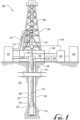
- FIG. 1 is an elevation view of an exemplary pulsed-power drilling system used to form a wellbore in a subterranean formation.
- FIG. 1 shows land-based equipment, downhole tools incorporating teachings of the present disclosure may be satisfactorily used with equipment located on offshore platforms, drill ships, semi-submersibles, and drilling barges (not expressly shown).
- wellbore 116 is shown as being a generally vertical wellbore, wellbore 116 may be or include any orientation including generally horizontal, multilateral, or directional.
- the exemplary drilling system 100 includes drilling platform 102 that supports derrick 104 having traveling block 106 for raising and lowering drill string 108.
- Drilling system 100 also includes pump 125, which circulates pulsed-power drilling fluid 122 (e.g. drilling mud) through a feed pipe to kelly 110, which in turn conveys pulsed-power drilling fluid 122 downhole through interior channels of drill string 108 and through one or more orifices in pulsed-power drill bit 114.
- Pulsed-power drilling fluid 122 then circulates back to the surface via annulus 126 formed between drill string 108 and the sidewalls of wellbore 116. Fractured portions of the formation are carried to the surface by pulsed-power drilling fluid 122 to remove those fractured portions from wellbore 116.
- Drilling fluid 122 may have rheological properties for removing cuttings from wellbore 116. Drilling fluid 122 may also have electrical properties conducive to particular pulse-powered drilling operations. Drilling fluid 122 may be or include oil-based fluids or water-based fluids, depending upon the particular pulsed power drilling approach used. Drilling fluid 122 may be formulated to have high dielectric strength and a high dielectric constant, so as to direct electrical arcs into the formation rather than them being short circuited through drilling fluid 122.
- Pulsed-power drill bit 114 is attached to the distal end of drill string 108 and may be an electrocrushing drill bit or an electrohydraulic drill bit. Power may be supplied to drill bit 114 from components downhole, components at the surface and/or a combination of components downhole and at the surface. For example, generator 140 may generate electrical power and provide that power to power-conditioning unit 142. Power-conditioning unit 142 may then transmit electrical energy downhole via surface cable 143 and a sub-surface cable (not expressly shown in FIG. 1 ) contained within drill string 108 or attached to the outer wall of drill string 108. While the drill string shown in FIG. 1 is typically includes drill pipe, in other embodiments coiled tubing may be used as the conveyance mechanism (as discussed below).
- a pulse-generating (PG) circuit within BHA 128 may receive the electrical energy from power-conditioning unit 142 and may generate high-energy electrical pulses to drive drill bit 114.
- the high-energy electrical pulses may discharge through the rock formation and/or drilling fluid 122 and, in some embodiments, may provide information about the properties of the formation and/or drilling fluid 122.
- the PG circuit within BHA 128 may be located near drill bit 114 (e.g. downhole and in proximity to the drill bit).
- the PG circuit may include a power source input, including two input terminals, and a first capacitor coupled between the input terminals.
- the pulse generating circuit may include a first inductor coupled between the input terminals with associated opening switch and a first capacitor coupled to the two ends of the inductor.
- the PG circuit may also include a switch, a transformer, and a second capacitor whose terminals are coupled to respective electrodes of drill bit 114.
- the switch may include a mechanical switch, a solid-state switch, a magnetic switch, a gas switch, or any other type of switch suitable to open and close the electrical path between the power source input and a first winding of the transformer.
- the transformer can generate a current through a second winding when the switch is closed and current flows through first winding. The current through the second winding can charge the second capacitor. As the voltage across the second capacitor increases, the voltage across the electrodes of the drill bit increases.
- the transformer may be a segmented primary transformer including multiple primary windings and a single secondary winding.
- the transformer may be a magnetic core transformer.
- the pulse generating circuit may also include a first inductor coupled between the input terminals with an associated opening switch and a second capacitor whose terminals are coupled to each end of the first inductor and to respective electrodes of drill bit 114.
- the first inductor may be an air core inductor or a magnetic core inductor and may generate the full voltage needed by the second capacitor for drilling.
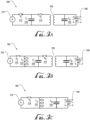
- the inductor may be a segmented inductor including multiple windings with respective opening switches. Three example PG circuits are illustrated in FIGS. 3A through 3C , respectively.
- the pulse-generating circuit within BHA 128 may be utilized to repeatedly apply a high electric potential, for example up to or exceeding 150 kV (e.g. approximately 150-300 kV), across the electrodes of pulsed-power drill bit 114. Each application of electric potential is referred to as a pulse.
- a pulse When the electric potential across the electrodes of pulsed-power drill bit 114 is increased enough during a pulse to generate a sufficiently high electric field, an electrical arc forms through a rock formation at the bottom of wellbore 116. The arc temporarily forms an electrical coupling between the electrodes of pulsed-power drill bit 114, allowing electric current to flow through the arc inside a portion of the rock formation at the bottom of wellbore 116.
- the arc greatly increases the temperature and pressure of the portion of the rock formation through which the arc flows and the surrounding formation and materials.
- the temperature and pressure are sufficiently high to break the rock itself into small bits or cuttings.
- This fractured rock is removed, typically by pulsed-power drilling fluid 122, which moves the fractured rock away from the electrodes and uphole.
- uphole and downhole may be used to describe the location of various components of drilling system 100 relative to the bottom or end of wellbore 116 shown in FIG. 1 .
- a first component described as uphole from a second component may be further away from the end of wellbore 116 (e.g. closer to the surface) than the second component.
- a first component described as being downhole from a second component may be located closer to the end of wellbore 116 (e.g. further from the surface) than the second component.
- Wellbore 116 As pulsed-power drill bit 114 repeatedly fractures the rock formation and pulsed-power drilling fluid 122 moves the fractured rock uphole, wellbore 116, which penetrates various subterranean rock formations 118, is created and/or extended.
- Wellbore 116 may be any hole drilled into a subterranean formation or series of subterranean formations for the purpose of exploration or extraction of natural resources such as, for example, hydrocarbons, or for the purpose of injection of fluids such as, for example, water, wastewater, brine, or water mixed with other fluids.
- wellbore 116 may be any hole drilled into a subterranean formation or series of subterranean formations for the purpose of geothermal power generation.
- pulsed-power drill bit 114 is described above as implementing electrocrushing drilling, pulsed-power drill bit 114 may also be used for electrohydraulic drilling, rather than generating an electrical arc within the rock, drill bit 114 applies a large electrical potential across one or more electrodes and a ground ring to form an arc across the drilling fluid proximate to the downhole end of wellbore 116.
- the high temperature of the arc vaporizes the portion of the drilling fluid immediately surrounding the arc, which in turn generates a high-energy shock wave in the remaining fluid.
- the one or more electrodes of electrohydraulic drill bit may be oriented such that the shock wave generated by the arc is transmitted toward the bottom of wellbore 116.
- wellbore 116 may be formed in subterranean formation 118 using drill bit 114 that implements either electrocrushing or electrohydraulic drilling.
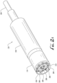
- FIG. 2A is a perspective view of components of an exemplary bottom-hole assembly for a pulsed-power drilling system.
- BHA 128 may include pulsed-power tool 230 and drill bit 114.
- pulsed-power drill bit 114 may be integrated within BHA 128, or may be a separate component that is coupled to BHA 128 (e.g. typically at its downhole end).
- Pulsed-power tool 230 may provide pulsed electrical energy to drill bit 114.
- Pulsed-power tool 230 receives electrical power from a power source via cable 220.
- pulsed-power tool 230 may receive electrical power via cable 220 from a power source located on the surface as described above with reference to FIG. 1 .
- pulsed-power tool 230 may receive electrical power from a power source located downhole such as a generator powered by a mud turbine.
- Pulsed-power tool 230 may receive electrical power via a combination of a power source located on the surface and a power source located downhole.
- Drill bit 114 may include one or more electrodes 208 and 210 and ground ring 250, shown in part in FIG. 2A .
- Ground ring 250 may function as an electrode.
- Pulsed-power tool 230 converts electrical power received from the power source into pulse drilling signals in the form of high-energy electrical pulses that are applied across electrodes 208 and/or 210 and ground ring 250 of drill bit 114.
- Pulsed-power tool 230 may include a pulse-generating circuit as described above with reference to FIG. 1 .
- pulsed-power drilling fluid 122 may exit drill string 108 via openings 209 surrounding each electrode 208 and each electrode 210.
- the flow of pulsed-power drilling fluid 122 out of openings 209 allows electrodes 208 and 210 to be insulated by the drilling fluid.
- Pulsed-power drill bit 114 may include a solid insulator (not expressly shown in FIG. 1 or 2A ) surrounding electrodes 208 and 210 and one or more orifices (not expressly shown in FIG. 1 or 2A ) on the face of pulsed-power drill bit 114 through which pulsed-power drilling fluid 122 exits drill string 108.
- Such orifices may be simple holes, or they may be nozzles or other shaped features.
- pulsed-power drilling fluid 122 may not need to exit the drill bit at as high a pressure as the drilling fluid in mechanical drilling. As a result, nozzles and other features used to increase drilling fluid pressure may not be needed. However, nozzles or other features to increase pulsed-power drilling fluid 122 pressure or to direct pulsed-power drilling fluid may be included for some uses.
- Pulsed-power drilling fluid 122 (e.g. drilling mud) is typically circulated through drilling system 100 at a flow rate sufficient to remove fractured rock from the vicinity of pulsed-power drill bit 114 (e.g. moving the fractured rock material uphole).
- pulsed-power drilling fluid 122 may be under sufficient pressure at a location in wellbore 116, particularly a location near a hydrocarbon, gas, water, or other deposit, to prevent a blowout.
- pulsed-power drill bit 114 may include ground ring 250, shown in part in FIG. 2A .
- Ground ring 250 may function as an electrode. Although illustrated as a contiguous ring in FIG. 2A , ground ring 250 may be non-contiguous discrete electrodes and/or implemented in different shapes. Electrodes 208 and 210 may be at least 0.4 inches (i.e., at least approximately 10 millimeters) apart from ground ring 250 at their closest spacing, at least 1 inch apart at their closest spacing, at least 1.5 inches (i.e., at least approximately 38 millimeters) apart at their closest spacing, or at least 2 inches (i.e., at least approximately 51 millimeters) apart at their closest spacing.
- Pulsed-power drilling fluid 122 may be circulated at a flow rate also sufficient to remove vaporization bubbles from the vicinity of electrocrushing drill bit 114.
- pulsed-power drill bits 114 may have ground ring 250, if it is present, it may contain passages 260 to permit the flow of electrocrushing drilling fluid 122 along with any fractured rock or bubbles away from electrodes 208 and 210 and uphole.
- FIG. 2B is a perspective view of another exemplary components of a bottom-hole assembly for downhole pulsed-power drilling system 100.
- BHA 128 may include pulsed-power tool 230 and drill bit 114.
- drill bit 114 maybe integrated within BHA 128, or may be a separate component that is coupled to BHA 128.
- BHA and pulsed-power tool 230 may include features and functionalities discussed above in FIG. 2A .
- pulsed-power drilling fluid 122 may exit drill string 108 via opening 213 surrounding electrode 212. The flow of pulsed-power drill fluid 122 out of opening 213 allows electrode 212 to be insulated by the pulsed-power drilling fluid. While one electrode 212 is shown in FIG.
- pulsed-power drill bit 114 may include multiple electrodes 212. Pulsed-power drill bit 114 may include solid insulator 210 surrounding electrode 212 and one or more orifices (not expressly shown in FIG. 2B ) on the face of pulsed-power drill bit 114 through which pulsed-power drilling fluid 122 exits drill string 108. Nozzles or other features to increase pulsed-power drilling fluid 122 pressure or to direct pulsed-power drilling fluid may be included for some uses. Additionally, the shape of solid insulator 210 may be selected to enhance the flow of pulsed-power drilling fluid 122 around the components of pulsed-power drill bit 114.
- Ground ring 250 may function as an electrode and provide a location on the pulsed-power drill bit where an arc may initiate and/or terminate.
- Drill bit 114 may also include one or more fluid flow ports 260 on the face of the drill bit through which drilling fluid exits the drill string 108.
- ground ring 250 of drill bit 114 may include one or more fluid flow ports 260 such that pulsed-power drilling fluid 122 flow through fluid flow ports 260 carry fractured rock and vaporization bubbles away from the drilling area.
- Fluid flow ports 260 may be simple holes, or they may be nozzles or other shaped features. Drilling fluid 122 is typically circulated through drilling system 100 at a flow rate sufficient to remove fractured rock from the vicinity of drill bit 114.
- drilling fluid 122 may be under sufficient pressure at a location in wellbore 116, particularly a location near a hydrocarbon, gas, water, or other deposit, to prevent a blowout.
- Drilling fluid 122 may exit drill string 108 via opening 213 surrounding electrode 212.
- the flow of drilling fluid 122 out of opening 213 allows electrode 212 to be insulated by the drilling fluid.
- drilling fluid 122 may not need to exit the drill bit at as high a pressure as the drilling fluid in mechanical drilling.
- nozzles and other features used to increase drilling fluid pressure may not be needed on drill bit 114.
- nozzles or other features to increase drilling fluid 122 pressure or to direct drilling fluid may be included for some uses.
- the shape of solid insulator 20 may be selected to enhance the flow of drilling fluid 122 around the components of drill bit 114.
- the pulsed-power drilling systems described herein may generate multiple electrical arcs per second using a specified excitation current profile that causes a transient electrical arc to form and arc through the most conducting portion of the wellbore floor.
- the arc causes that portion of the wellbore floor to disintegrate or fragment and be swept away by the flow of drilling fluid.
- subsequent electrical arcs may naturally seek the next most conductive portion. Therefore, obtaining measurements from which estimates of the excitation direction can be generated may provide information usable in determining characteristics of the formation.
- the electrical pulses used for electrocrushing drilling may be generated using any of a variety of PG circuits including, but not limited to, circuits that include capacitive energy storage elements and circuits that include inductive energy storage elements.
- FIGS. 3A through 3C illustrate three non-limiting examples of PG circuits.
- PG circuit 302 illustrated in FIG. 3B , is configured to use an inductor for charging the primary capacitor C1 (320), which in turn is switched to the transformer (350) to charge a secondary capacitor, shown as output capacitor CO (330).
- current runs from the alternator (310) through an isolation and opening switch S3 (316) through an inductor L1 (322) to store energy in the magnetic field. When that current is interrupted by opening switch S3 (316), a large voltage is created across inductor L1 (322).
- This example PG circuit 302 uses an opening switch S3 (316) that first closes to connect inductor L1 (322) to the alternator (310), or another power source, and then on command opens to interrupt that current flow, creating a voltage across inductor L1 (322).
- opening switches such as S3 (316) may need to be capable of high-voltage standoff.
- the voltage pulse from inductor L1 (322) charges primary capacitor C1 (320), which is then switched into the transformer (350) via switch S2 (314).
- PG circuit 302, inductor L1 (322) and opening switch S3 (316) may be used to step up the voltage output from the alternator (310).
- PG circuit 302 uses inductive energy storage.
- PG circuit 304 illustrated in FIG. 3C , is configured to use the voltage output from an inductor L2 (332) to directly charge a secondary capacitor, shown as output capacitor CO (330, eliminating the transformer.
- the rising voltage on output capacitor CO (330) which is coupled to a drill bit (340), creates the electrical arc that fractures the rock.
- the high voltage requirements for the corresponding opening switch, shown as S4 (318), may be significant.
- one or more sensors may be located in the wellbore, for example disposed on or in the BHA.
- the sensors may be configured to transmit measured sensor data to the surface.
- a communication and/or fiber-optic cable may communicatively couple the one or more downhole sensors to the surface (e.g. to a processor and/or controller on the surface).
- the downhole sensors may be part of a measurement system.
- the measurement system (with downhole sensors) may be configured for example to detect, receive, and/or measure an electric and/or magnetic field.
- the sensors may include any type of sensor that records responses from electromagnetic and/or acoustic waves.
- the downhole sensors of the measurement system may include one or more (or in some instances, an array) of acoustic sensors which may be used within the wellbore.
- the acoustic sensors may be positioned at different locations within the wellbore and/or may be oriented in different directions to record responses to propagating acoustic waves.
- the acoustic sensors may be configured to provide information about the surrounding formation at various depths, which may be used to form a three-dimensional image of the surrounding subterranean features in some embodiments.
- the sensors may be integrated in the pulsed-power tool 230 or may be separate sensors within the BHA 128, such as within a measurement while drilling (MWD) system.
- MWD measurement while drilling
- Some embodiments may include a processing unit, which may be coupled to one or more input/output interfaces and/or data storage, for example over an interconnect.
- An exemplary interconnect may be implemented using any suitable computing system interconnect mechanism or protocol.
- Some embodiments of the processing unit may be configured to determine characteristics of a formation ahead of the drilling tool based, at least in part, on inputs received by input/output interfaces, some of which may include measurements representing responses recorded by various sensors within the wellbore, such as voltages, currents, ratios of voltages to current, electric field strengths or magnetic field strengths.
- processing unit may be configured to perform one or more inversions based on simulation models that relate the electromagnetic properties of the formation to electromagnetic data collected by downhole sensors and/or relate the acoustic properties of the formation to acoustic data collected by downhole sensors.
- the processing unit (which may serve as a controller for the pulsed-power drilling system 100 in some embodiments) may be disposed at the surface.
- the processing unit may include a processor, that is any system, device, or apparatus configured to interpret and/or execute program instructions and/or process.
- the processor may be or include, without limitation, a microprocessor, microcontroller, digital signal processor (DSP), application specific integrated circuit (ASIC), or any other digital or analog circuitry configured to interpret and/or execute program instructions and/or process data.
- the processor may interpret and/or execute program instructions and/or process data stored in one or more computer-readable media included in the processing unit.
- computer-readable media may be communicatively coupled to the processor and may include any system, device, or apparatus configured to retain program instructions and/or data for a period of time (e.g., computer-readable media).
- Computer-readable media may include random access memory (RAM), read-only memory (ROM), solid state memory, electrically erasable programmable read-only memory (EEPROM), disk-based memory, a PCMCIA card, flash memory, magnetic storage, opto-magnetic storage, or any suitable selection and/or array of volatile or non-volatile memory that retains data after power to the processing unit is turned off.
- RAM random access memory
- ROM read-only memory
- EEPROM electrically erasable programmable read-only memory
- disk-based memory e.g., solid state memory
- PCMCIA card erasable programmable read-only memory
- input/output interfaces may be coupled to an optical fiber (e.g. a fiber optic cable), such as an optical fiber element of telemetry mechanism, over which it may send and receive signals.
- Signals received by input/output interfaces may include measurements representing responses recorded by various sensors at the surface or downhole during a pulsed-drilling operation.
- signals received by input/output interfaces may include measurements representing responses recorded by various acoustic, electrical or electromagnetic sensors. These measurements may include, without limitation, measurements of voltage, current, electric field strength, or magnetic field strength.
- these and other inputs may be received using communication interfaces or telemetry mechanisms other than an optical fiber including, but not limited to, mechanisms for receiving acoustic, electric or electromagnetics signals, and various mechanical telemetry methods.
- control signals relating to the pulsed-power drilling system 100 may be communicated to one or more electrical or mechanical components located downhole via input/output interfaces using any suitable communication protocol interfaces or telemetry mechanisms.
- a control signal may be sent electrically over a power cable (e.g., over surface cable 143 illustrated in FIG. 1 and a sub-surface cable, or over cable 220 illustrated in FIG. 2A or 2B ) or over a separate control cable, via an optical fiber (e.g. a fiber optic cable), a wireline or a wired pipe, or via acoustic, mud pulse, or electromagnetic telemetry.
- an electrical or mechanical control signal may be communicated directly to a configurable electrical or mechanical component downhole that is to be adjusted.
- the control signal when the control signal does not convey actuation energy, the control signal may be communicated to an intermediate downhole component that receives the control signal and translates it.
- the intermediate downhole component may engage a power supply for the actuation, such as a battery, a generator power, or power received from the surface over a cable that is switched on, in a controlled manner.
- the intermediate downhole component may include a downhole electrical actuator or a downhole mechanical actuator. While control signals may be used to operate any number of downhole tool elements (e.g. associated with the pulsed-power drilling system), in some embodiments the control signals may be useful in steering the pulsed-power drilling system as it forms the wellbore.
- the tool string/drill string 108 may be configured to be steerable, for example as a rotary steerable tool. In some embodiments, this may provide full three-dimensional (3D) directional control of the drill bit.
- the tool string may include one or more logging while drilling (LWD) or measurement-while-drilling (MWD) tools that collect measurements relating to various borehole and formation properties as well as the position of the drill bit and various other drilling conditions as the drill bit extends the borehole of the wellbore through the formations.
- LWD logging while drilling
- MWD measurement-while-drilling
- the LWD/MWD tool may include a device for measuring formation resistivity, a gamma ray device for measuring formation gamma ray intensity, devices for measuring the inclination and azimuth of the tool string, pressure sensors for measuring fluid pressure, temperature sensors for measuring borehole temperature, or any other downhole tool or combination thereof.
- the tool string 108 may also be configured for telemetry (e.g. by including a telemetry module).
- the telemetry module may receive data provided by the various sensors of the tool string 108 (for example, sensors of the LWD/MWD tool), and transmit the data to a surface control unit (which may be a processing unit as described herein). Data may also be provided by the surface control unit, received by the telemetry module, and transmitted to the tools (for example, LWD/MWD tool, rotary steering tool, pulsed-power drill bit, or any other tool) of the tool string 108.
- the tools for example, LWD/MWD tool, rotary steering tool, pulsed-power drill bit, or any other tool
- fiber optic telemetry, mud pulse telemetry, wired drill pipe, acoustic telemetry, or other telemetry technologies known in the art may be used to provide communication between the surface control unit and the telemetry module.
- the surface control unit may communicate directly with the LWD/MWD tool, the rotary steering tool or both.
- the surface control unit may be stationed at the well site, a portable electronic device, a remote computer, or distributed between multiple locations and devices.
- the surface control unit may also be a control unit that controls functions of equipment of the tool string.
- Steering systems may, for example, allow the well's trajectory to be corrected or altered in response to the measurements taken by the sensors.
- the steering system can be configured to change the direction of the tool string, the drill bit or both, such as based on information indicative of tool orientation and a desired drilling direction and/or operation of an extendable member assembly.
- an exemplary extendable member assembly may comprise an extendable member and an extendable member diagnostic assembly.
- the steering system may be coupled to the drill bit and drive rotation of the drill bit.
- the steering system (e.g. rotary steerable tool) can rotate in tandem with the drill bit.
- the rotary steerable tool may be a point-the-bit system or a push-the-bit system.
- the steering system may comprise one or more sensors for making any measurement, including measurement while drilling data, logging while drilling data, formation evaluation data, temperature, pressure, velocity, speed, any other downhole data or any combination thereof.
- the conveyance mechanism for the pulsed-power drill bit 114 can be coiled tubing in some embodiments.
- coiled tubing is relatively flexible continuous tubing that can be run into the wellbore from a large spool mounted on a truck or other support structure.
- the spool typically has an axle, allowing rotation of the spool thereabout.
- a rig using drilling pipe must stop periodically to make up or break down connections when running drilling pipe into or out of the wellbore
- coiled tubing can be run in for substantial lengths before stopping to join in another strand of coiled tubing, thereby saving time with reference to jointed pipe.
- coiled tubing may provide improved steering maneuverability, for example due to its flexibility.
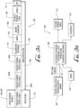
- FIG. 4 illustrates an exemplary system for deploying coiled tubing 422 downhole.
- Coiled tubing 422 which typically is relatively small and flexible tubing, is normally stored on a reel or spool 450 when not in use.
- FIG. 4 relates to a generic coiled tubing system, and illustrates generic coiled tubing 422.
- similar systems may be used with pulsed-power coiled tubing of the sort described herein and shown, for example, in FIGS. 5-7B .
- Exemplary coiled tubing 422 may be formed of steels having yield strengths ranging from 55,000 PSI to 120,000 PSI or of composite materials (e.g.
- Coiled tubing 422 may be available in diameters of 0.75 to 4.5 inches, 1 to 3.5 inches, approximately 4.5 inches, or approximately 2 inches, and may range in length from 2,000 to more than 30,000 ft (e.g. 600 to 9,000 m).
- coiled tubing 422 is coiled in a single continuous length, thus precluding any need for making or breaking connections between joints, although embodiments may include coiled tubing 422 which is formed by connecting two or more coiled tubing elements/segments (e.g. from two or more spools of coiled tubing) end-to-end (e.g. serially).
- the injector mechanism 412 may be configured to pull the tubing from the spool 450, straighten the tubing, and then inject the tubing downhole, for example through a seal assembly at the wellhead known as a "stuffing box.”
- the injector mechanism 412 may be capable of injecting thousands of feet of coiled tubing 422 with the tool string connected at the bottom end thereof into the well.
- the coiled tubing 422 may be supported by a gooseneck coupled to a mast or other supporting structure.
- the distribution subsystem 518 of the tool string 108 is shown as comprising a 3-in-1 connector 520b, which may be configured for input from the coiled tubing 422 and distribution of drilling fluid (e.g. drilling mud), power, and fiber/wire telemetry to the tool string 108, for example as it is deployed downhole in a wellbore.
- the tool string 108 is disposed (e.g. coupled) at the downhole end 514 of the coiled tubing 422, and the coiled tubing input interface subsystem 510 is disposed (e.g. coupled) at the uphole end 512 of the coiled tubing 422, as shown in FIG. 5 .
- FIG. 5 In FIG.
- the coiled tubing 422 has mating 3-in-1 connectors 520 a, b at the uphole end 512 and the downhole end 514 (e.g. with the uphole end 3-in-1 connector 520 b of the coiled tubing 422 configured to mate with the 3-in-1 connector 520a of the coiled tubing input interface subsystem 510, and with the downhole end 3-in-1 connector 520a of the coiled tubing 422 configured to mate with the distribution subsystem 518 of the tool string 108).
- 3-in-1 connectors 520 a, b at the uphole end 512 and the downhole end 514
- the uphole end 3-in-1 connector 520 b of the coiled tubing 422 configured to mate with the 3-in-1 connector 520a of the coiled tubing input interface subsystem 510
- the downhole end 3-in-1 connector 520a of the coiled tubing 422 configured to mate with the distribution subsystem 518 of the tool string 108.
- the coiled tubing 422 may comprise two or more coiled tubing elements/segments (e.g. 605 a, b, c) coupled end-to-end (e.g. in series) to allow fluid flow and power transmission therethrough from an uphole end 512 of a first coiled tubing element to a downhole end 514 of a second coiled tubing element (for example as shown in FIG. 6A ).
- Each coiled tubing element 605 may comprise a fluid tubing element and a cable conduit/tube element, for example so that jointly the coupled coiled tubing elements may effectively transmit drilling fluid and power downhole.
- the drilling fluid (e.g. mud) pumped downhole may comprise dielectric drilling fluid, which may be particularly useful in the context of pulsed-power drilling.
- System embodiments may further include a spool 450 (e.g. similar to that shown in FIG. 4 ), with at least a portion of the coiled tubing 422 disposed on the spool 450.
- the coiled tubing 422 of the present disclosure may be transported to the drill site on a spool 450.
- the coiled tubing 422 may be unwound from the spool 450 as it is fed downhole, and may be re-wound onto the spool 450 as it is retracted/removed from the wellbore.
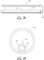
- FIG. 7A illustrates a longitudinally sectioned elevation view of an exemplary coiled tubing 422 embodiment
- FIG. 7B illustrates a radially sectioned view of the exemplary coiled tubing 422 embodiment of FIG. 7A
- Exemplary coiled tubing 422 embodiments for pulsed-power drilling downhole operations may comprise a flexible hollow fluid tube 560, configured to transport drilling fluid (e.g. drilling mud) therein (e.g. the length of the fluid tube 560, from a first end to a second end), and a flexible cable conduit (which may be a cable tube 550 in some embodiments).
- the cable conduit typically extends substantially the length of the fluid tube 560 (e.g.
- coiled tubing 422 embodiments disclosed herein are not so limited and are intended to include embodiments with multiple cable conduits.
- the one or more cable 553 within the cable conduit may comprise a power cable 553a for transmitting power from the surface power source (e.g. generator 140) to the pulse-power drill bit 114.
- the one or more cable 553 within the cable conduit may further comprise one or more selected from the following: a communication cable, fiber optic cable, a coaxial cable, and an auxiliary power cable.
- the one or more cable 553 within the cable conduit may comprise a power cable 553a, a communication cable 553b, and a fiber-optic cable 553c.
- the cable conduit (e.g. cable tube 550) may be disposed within the fluid tube 560.
- the cable conduit and the fluid tube 560 may be concentrically arranged, while in other embodiments, the inner cable conduit may be disposed anywhere within the outer fluid tube 560. This configuration may allow for the outer fluid tube 560 to protect and support the inner cable conduit.
- the cable conduit may be a cable tube 550, which may comprise hollow protective tubing 557, with the one or more cables 553 disposed therein and extending substantially the length of (e.g. slightly longer than) the protective tubing 557.
- the connector may comprise one or more separate connectors.
- one or more separate connector may be used at each end in conjunction with one or more integrated multi-connector.
- a single integrated multi-connector may be used at each end for all of the cables 553 of the cable tube 550, while the protective tubing connector and/or fluid tube connector at each end may be a separate connector.
- the separate connectors for each end of each cable 553 may comprise a clamping mechanism configured to splice a conductor of the one or more cable 553, fix the position of the conductor, and/or isolate/shield the conductor at the splice (e.g. to prevent any electrical shorting or inadvertent grounding due to a break in the insulation around the conductor in the vicinity of the splice).
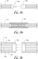
- FIG. 8B illustrates schematically a longitudinal cross-sectional view of such an exemplary connector for a cable 553 within an exemplary cable tube 550 of an exemplary coiled tubing 422 embodiment.
- the conductor of the cable 553 in the coiled tube may be spliced to a conductor in either an adjacent coiled tube cable, the coiled tubing input interface subsystem 510, or the distribution subsystem 518 of the tool string 108 respectively, with the conductors abutting or overlapping and being crimped or clamped together.
- FIG. 8B illustrates an exemplary clamping sleeve 820, which may insulate the connection and securely fix the connection.
- each cable 553 in the cable tube 550 may be configured to be individually spliced or otherwise connected.
- the separate connectors for each of the cables 553 at each end of the cable tube 550 may be axially spaced (e.g. with respect to each other).
- the protective tubing 557 may be wider (e.g. have a larger diameter) at the location of connection/slicing.
- FIGS. 8A-B are merely illustrative, and other mechanisms may be used for the connector.
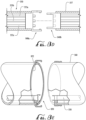
- the connector at each end of the cable tube 550 may comprise an integrated multi-connector configured so that connection (e.g. mating attachment) of the integrated multi-connector connects (e.g. matingly) each of the one or more cable 553 (e.g. allowing each cable 553 at an end of the cable tube 550 to be plugged in simultaneously).
- FIG. 8C illustrates such an exemplary embodiment, with an integrated multi-connector 830 a, b for all cables 553 in a cable tube 550. In FIG. 8C , plugging in the integrated multi-connector 830 simultaneously plugs in each cable 553 of the cable tube 550.
- FIG. 8C is merely illustrative, and other mechanisms may be used for the integrated multi-connector.
- the coiled tubing 422 may comprise two or more coiled tubing elements 605 coupled end-to-end (e.g. in series) to allow fluid flow therethrough from an uphole end 512 of a first coiled tubing element to a downhole end 514 of a second coiled tubing element.
- FIG. 6A illustrates such an embodiment.
- each coiled tubing element 605 may comprise a fluid tubing element and a cable tube element.
- the protective tubing 557 of the cable tube 550 may be configured to protect the one or more cable 553 therein from drilling fluid within the fluid tube 560.
- the protective tubing 557 may be sufficiently corrosive and/or abrasive resistant so that the drilling fluid in the fluid tube 560 does not damage the protective tubing 557 enough to allow ingress of the drilling fluid into the cable tube 550 in a way that might compromise the cables therein.
- the outer fluid tube 560 may have sufficient mechanical strength to support a drilling tool string 108, as well as sufficiently corrosion and/or abrasion resistance to protect the cable tube 550 from drilling fluid outside the fluid tube 560 in the wellbore with fractured rock cuttings (e.g.
- the fluid tube 560 may have similar characteristic to general coiled tubing 422, for example as discussed above with respect to FIG. 4 .
- the fluid tube 560 may be formed of steel.
- the inner diameter of the fluid tube 560 may be sufficient for effective drilling fluid flow downhole and circulation uphole to remove fractured rock cuttings during pulsed-power drilling operations (e.g. despite the presence of the inner cable tube 550 within the outer fluid tube 560).
- the fluid tube 560 may be configured to transport dielectric drilling fluid.
- the coiled tubing 422 may have a smooth exterior surface (e.g. a smooth cylindrical surface), integral power cable, and no loose or separate power line. Some embodiments of the coiled tubing 422 may further comprise one or more safety sensor (e.g. disposed in the connector). Some embodiments of the coiled tubing 422 may further comprise an interlock system 570 (e.g. configured to provide and/or detect a secure connection).
- the cable conduit/cable tube 550 may be disposed on an interior surface of the fluid tube 560.
- the cable conduit/cable tube 550 may be secured to the interior surface of the fluid tube 560 for substantially its entire length.
- the cable conduit is generally described herein as being disposed within the fluid tube 560 (which may have benefits when rolling and unrolling the coiled tubing 422 on a spool 450, for example), in other embodiments the cable conduit may be disposed on an exterior surface of the fluid tube 560 (see for example, FIG. 6A ).
- Some or all of the features of the inner cable tube 550 may apply equally to an exterior cable conduit in various embodiments.
- Disclosed embodiments may also include methods of forming coiled tubing 422 having an inner cable tube 550 within an outer fluid tube 560.
- Exemplary methods may comprise providing the cable tube 550 having one or more cables 553 disposed within protective tubing 557; forming the fluid tube 560 to encompass the inner cable tube 550; and anchoring both ends of the cable tube 550 to the fluid tube 560.
- a remainder of the length of the cable tube 550 e.g. between the anchored ends
- the cables 553 within the protective tubing 557 of the cable tube 550 may be anchored at both ends of the cable tube 550 (e.g. with the remainder of the length of the cables free-floating).
- the cables 553 within the protective tubing 557 of the cable tube 550 may have sufficient slack so that the cables 553 are supported by the protective tubing 557 (e.g. carry no load).
- the cable tube 550 may further comprise one or more connector disposed at each end.
- the one or more connectors may anchor the cables 553 to the protective tubing 557 and/or may be configured to provide removable coupling/connect.
- the one or more connectors may comprise a protective tubing connector configured to provide a seal (e.g. a sealed connection).
- the fluid tube 560 may be configured with a connector at each end to allow for connection/coupling to a fluid element.
- the fluid tube connector may be configured to provide a seal.
- the fluid tube connector may be configured so that connection of the fluid tube 560 automatically ensures connection of the cable tube 550 and the cables 553 therein.
- the method embodiments may further comprise selecting material for the fluid tube 560 and the protective tubing 557.
- the fluid tube 560 material may be more resistant to abrasion and puncture than the protective tubing 557 material.
- the method embodiments may further comprise selecting wall thickness for the fluid tube 560 and the protective tubing 557.
- the fluid tube 560 and the protective tubing 557 may be formed of the same or similar material, but the fluid tube 560 may have a thicker wall thickness.
- Method embodiments may further comprise selecting a first length for the fluid tube 560 and a second length for the protective tubing 557, wherein the second length is (slightly) greater than the first length.
- Method embodiments may further comprise selecting a third length for each of the cables 553 of the cable tube 550, wherein the third length is greater than the second length. It should be understood that one or more of the cables 553 may have a distinct length, but for example each of the cables in such an embodiment may have a length greater than the second length.
- forming the fluid tube 560 to encompass the inner cable tube 550 may comprise pulling the cable tube 550 through a hollow bore of the fluid tube 560. In other embodiments, forming the fluid tube 560 to encompass the inner cable tube 550 may comprise manufacturing the outer fluid tube 560 around the inner cable tube 550.
- the outer fluid tube 560 can be formed and rolled into a circular/cylindrical/tubular shape with the already assembled inner cable tube(s) 550 in place (e.g. during the rolling process), for example with the material (e.g.
- the metal/steel plate for the fluid tube 560 being rolled around the cable tube(s) 550 so that the cable tube(s) 550 will be in position inside the fluid tube 560 once the rolling and welding (e.g. the rolled material for the fluid tube 560 may be welded into final tubular shape) are completed.
- providing the cable tube 550 may comprise forming the cable tube 550 having one or more cables 553 extending lengthwise through the protective tubing 557.
- forming the cable tube 550 may comprise pulling the one or more cables 553 through the hollow bore of the protective tubing 557.
- forming the cable tube 550 may comprise manufacturing the protective tubing 557 around the one or more cables 553.
- the inner cable tube(s) 550 may first (e.g. before formation of the fluid tube 560) be manufactured as a completed assembly using similar rolling methods as discussed above with respect to the fluid tube 560.
- the material (e.g. metal/steel plate) of the protective tubing 557 may be rolled around the one or more cables 553 (e.g.
- the entire cable tube 550 assembly can then optionally be pulled through a dye to reduce the tube diameter, for example to provide an interference fit of the protective tubing 557 over the one or more cables 553 (e.g. the power cable).
- Disclosed embodiments also include methods of drilling a wellbore.
- method embodiments may comprise connecting and/or coupling a tool string 108 having a pulsed power drill bit to a downhole end 514 of coiled tubing 422; deploying (e.g. running) the coiled tubing 422 downhole; directing and/or supplying power to the tool string 108 via the coiled tubing 422 (e.g. via the cable tube 550 within the fluid tube 560); providing drilling fluid downhole through the coiled tubing 422 (e.g. via the fluid tube 560); and drilling the wellbore using the pulsed-power drill bit 114.
- the coiled tubing 422 may comprise any embodiments disclosed herein, for example with the coiled tubing 422 having a flexible hollow fluid tube 560 configured to transport drilling fluid therein; and a flexible cable tube 550 disposed within the fluid tube 560, wherein the cable tube 550 extends substantially the length of the fluid tube 560 and comprises one or more cable 553 disposed within protective tubing 557.
- the drilling fluid may be dielectric.
- drilling fluid and power may be simultaneously provided downhole through the coiled tubing 422 (e.g. with the protective tubing 557 protecting the cables 553 from the drilling fluid within the fluid tubing, as the cables transmit power, etc.).
- Embodiments may further comprise boosting the voltage of the power supplied through the coiled tubing 422, for example using a pulse-generating circuit in the tool string 108 (e.g. as previously discussed).
- Deploying the coiled tubing 422 downhole may comprise deploying (e.g. from a spool 450 of coiled tubing 422 on the surface) an amount of coiled tubing 422 sufficient to reach a desired drilling depth.
- Directing/supplying power may comprise selecting the amount of power based on the length of the coiled tubing 422 (e.g. less power for lesser depths, and more power for greater depths) and/or altering the amount of power supplied based on the length of the coiled tubing 422 in the wellbore.
- Some embodiments may further comprise connecting/coupling an uphole end 512 of the coiled tubing 422 to an input interface subsystem at the surface.
- a generator 140 or other power source may provide power to the input interface subsystem.
- a mud pump 125 may provide drilling fluid to the input interface subsystem.
- the coiled tubing 422 may comprise two coiled tubing elements 605, and the method may further comprise connecting a downhole end 514 of a second of the two coiled tubing elements to an uphole end 512 of a first of the two coiled tubing elements.
- connecting may comprise connecting fluidly (e.g. the fluid tube 560) and electrically/power (e.g. the cable tube 550 and its cables).
- connecting cables 553 may comprise splicing, wherein the splices are axially spaced.
- connecting may comprise connecting mating terminals for each cable 553.
- connecting may comprise connecting a single integrated multi-connector, whereby connecting the single integrated multi-connector connects all cables 553 simultaneously.
- connecting may further comprise connecting the protective tubing 557 of the cable tube 550 (e.g.
- connecting may further comprise connecting the fluid tubing (e.g. to provide a fluid-tight connection, so no drilling fluid can enter the cable tube 550 to contact the cables 553 therein).
- connecting cables 553 may comprise forming (e.g. splicing) connections radially outward (e.g. starting inward and working outward).
- connecting cables 553 may comprise forming (e.g. splicing) connections which are axially spaced.
- Some embodiments may further comprise sensing the connection(s) (e.g. using an interlock system 570) to ensure that all connections are effectively made.
- a signal may be sent to indicate a good connection, a bad connection, or both.
- all power for the pulsed-power drill bit 114 may be transmitted downhole through the coiled tubing 422 and/or all power generation for the pulsed-power drilling system may be at the surface.
- at least a portion of the wellbore may extend or be drilled at an angle from vertical (e.g. at least a portion of the wellbore is non-vertical).
- At least a portion of the wellbore can be drilled at an angle of approximately 10-90, 15-90, 20-90, 25-90, 30-90, 35-90, 40-90, 45-90, 50-90, 55-90, 60-90, 65-90, 70-90, 75-90, 80-90, 85-90, 10-60, 20-50, 30-75, 40-80, 20-70, 25-60, approximately 90, or even greater than 90 degrees from vertical (e.g. where 90 degrees from vertical would represent horizontal).
- Some embodiments of the method may further comprise steering the tool string 108.
- control/command signals may be transmitted downhole through the coiled tubing 422, which may allow control of the path of the pulsed-power drill bit 114 and/or the wellbore.
- the flexibility of the coiled tubing 422 may allow for greater angles for drilling of the wellbore and/or within wells formed by pulsed-power drill bit 114s (e.g. compared to drill pipe conveyance). Some embodiments may further comprise transmitting signals (e.g. sensor signals) to the surface though the coiled tubing 422.
- signals e.g. sensor signals
- the coiled tubing 422 may be rewound/re-rolled onto the spool 450 during removal from the wellbore.
- method embodiments may further comprise retracting the tool string 108 from the wellbore to the surface by rolling the coiled tubing 422 onto the spool 450.
- Some method embodiments may comprise controlling the depth of the tool string 108/pulsed-power drill (e.g. the position in the wellbore) by rolling and unrolling coiled tubing 422 from the spool 450 on the surface.
- any numerical range defined by two R numbers as defined in the above is also specifically disclosed.
- Language of degree used herein, such as “approximately,” “about,” “generally,” and “substantially,” represent a value, amount, or characteristic close to the stated value, amount, or characteristic that still performs a desired function or achieves a desired result.
- the language of degree may mean a range of values as understood by a person of skill or, otherwise, an amount that is +/-10%.
- the term "high-pressure" describing a manifold should be understood to refer to a manifold that receives pressurized fluid that has been discharged from a pump irrespective of the actual pressure of the fluid as it leaves the pump or enters the manifold.
- the term "low-pressure” describing a manifold should be understood to refer to a manifold that receives fluid and supplies that fluid to the suction side of the pump irrespective of the actual pressure of the fluid within the low-pressure manifold.
- the term "or” is inclusive unless otherwise explicitly noted. Thus, the phrase “at least one of A, B, or C” is satisfied by any element from the set ⁇ A, B, C ⁇ or any combination thereof, including multiples of any element.
- the term "and/or” includes any combination of the elements associated with the “and/or” term.
- the phrase “A, B, and/or C” includes any of A alone, B alone, C alone, A and B together, B and C together, A and C together, or A, B, and C together.
Landscapes
- Engineering & Computer Science (AREA)
- Life Sciences & Earth Sciences (AREA)
- Geology (AREA)
- Mining & Mineral Resources (AREA)
- Physics & Mathematics (AREA)
- Environmental & Geological Engineering (AREA)
- Fluid Mechanics (AREA)
- General Life Sciences & Earth Sciences (AREA)
- Geochemistry & Mineralogy (AREA)
- Mechanical Engineering (AREA)
- Earth Drilling (AREA)
Applications Claiming Priority (2)
| Application Number | Priority Date | Filing Date | Title |
|---|---|---|---|
| US18/244,729 US12331641B2 (en) | 2023-09-11 | 2023-09-11 | Pulsed-power drilling system with integrated power and communication coiled tubing conveyance |
| PCT/US2023/033704 WO2025058635A1 (fr) | 2023-09-11 | 2023-09-26 | Système de forage à puissance pulsée avec transport de colonne de production spiralée d'alimentation et de communication intégrées |
Publications (2)
| Publication Number | Publication Date |
|---|---|
| EP4520914A1 true EP4520914A1 (fr) | 2025-03-12 |
| EP4520914B1 EP4520914B1 (fr) | 2025-10-15 |
Family
ID=91759588
Family Applications (1)
| Application Number | Title | Priority Date | Filing Date |
|---|---|---|---|
| EP24185757.2A Active EP4520914B1 (fr) | 2023-09-11 | 2024-07-01 | Système de forage à puissance pulsée avec transport de tube spiralé de puissance et de communication intégré |
Country Status (1)
| Country | Link |
|---|---|
| EP (1) | EP4520914B1 (fr) |
Citations (3)
| Publication number | Priority date | Publication date | Assignee | Title |
|---|---|---|---|---|
| WO2013059315A1 (fr) * | 2011-10-17 | 2013-04-25 | Schlumberger Canada Limited | Câble à double utilisation doté d'une encapsulation de fibre optique et destiné à être utilisé dans des opérations de puits de forage |
| US20140008968A1 (en) * | 2012-07-05 | 2014-01-09 | Sdg, Llc | Apparatuses and methods for supplying electrical power to an electrocrushing drill |
| US20180374607A1 (en) * | 2017-06-27 | 2018-12-27 | Halliburton Energy Services, Inc. | Power and Communications Cable for Coiled Tubing Operations |
-
2024
- 2024-07-01 EP EP24185757.2A patent/EP4520914B1/fr active Active
Patent Citations (3)
| Publication number | Priority date | Publication date | Assignee | Title |
|---|---|---|---|---|
| WO2013059315A1 (fr) * | 2011-10-17 | 2013-04-25 | Schlumberger Canada Limited | Câble à double utilisation doté d'une encapsulation de fibre optique et destiné à être utilisé dans des opérations de puits de forage |
| US20140008968A1 (en) * | 2012-07-05 | 2014-01-09 | Sdg, Llc | Apparatuses and methods for supplying electrical power to an electrocrushing drill |
| US20180374607A1 (en) * | 2017-06-27 | 2018-12-27 | Halliburton Energy Services, Inc. | Power and Communications Cable for Coiled Tubing Operations |
Also Published As
| Publication number | Publication date |
|---|---|
| EP4520914B1 (fr) | 2025-10-15 |
Similar Documents
| Publication | Publication Date | Title |
|---|---|---|
| AU2003210744B2 (en) | Well system | |
| US12331641B2 (en) | Pulsed-power drilling system with integrated power and communication coiled tubing conveyance | |
| US7325606B1 (en) | Methods and apparatus to convey electrical pumping systems into wellbores to complete oil and gas wells | |
| AU743707B2 (en) | Well system | |
| US6868906B1 (en) | Closed-loop conveyance systems for well servicing | |
| CN1930361B (zh) | 用于建立地下井钻孔并在该钻孔中设置可膨胀的壳体或砂筛及完井管的方法和作业设备 | |
| US7896070B2 (en) | Providing an expandable sealing element having a slot to receive a sensor array | |
| CN1330845C (zh) | 钻凿孔眼方法、微钻钻具和混合式缆绳在该方法中的应用 | |
| US20080128128A1 (en) | Methods and apparatus to convey electrical pumping systems into wellbores to complete oil and gas wells | |
| CN107407141B (zh) | 用于钻井管状主体的内部牵引机系统 | |
| EP1210498B1 (fr) | Navettes intelligentes permettant d'achever les puits de petrole et de gaz | |
| CN107407129A (zh) | 井下液压喷射组件 | |
| GB2330161A (en) | Flexible extension for borehole logging instruments | |
| PT1978204E (pt) | Dispositivo de perfuração do solo | |
| CA2614679C (fr) | Systeme de forage a tube spirale | |
| JPS62242090A (ja) | 地中井戸ボ−リング装置およびそれを形成するための方法 | |
| EP4520914B1 (fr) | Système de forage à puissance pulsée avec transport de tube spiralé de puissance et de communication intégré | |
| EP1696101A1 (fr) | Système et procédé adapté à être utilisé pour le netoyage du puits pendant le forage | |
| US20250382851A1 (en) | Coiled tubing deployment/retrieval apparatus, a coiled tubing surface equipment spread, and method that employ a power cable injector | |
| US20090084542A1 (en) | Wellbore power and/or data transmission devices and methods | |
| GB2589815A (en) | Telemetry safety & life of well monitoring system | |
| GB2584450A (en) | Telemetry safety & life of well monitoring system | |
| NO20180235A1 (en) | A method and apparatus for simultaneously drilling and in-situ casing installation |
Legal Events
| Date | Code | Title | Description |
|---|---|---|---|
| PUAI | Public reference made under article 153(3) epc to a published international application that has entered the european phase |
Free format text: ORIGINAL CODE: 0009012 |
|
| STAA | Information on the status of an ep patent application or granted ep patent |
Free format text: STATUS: EXAMINATION IS IN PROGRESS |
|
| 17P | Request for examination filed |
Effective date: 20240701 |
|
| AK | Designated contracting states |
Kind code of ref document: A1 Designated state(s): AL AT BE BG CH CY CZ DE DK EE ES FI FR GB GR HR HU IE IS IT LI LT LU LV MC ME MK MT NL NO PL PT RO RS SE SI SK SM TR |
|
| GRAP | Despatch of communication of intention to grant a patent |
Free format text: ORIGINAL CODE: EPIDOSNIGR1 |
|
| STAA | Information on the status of an ep patent application or granted ep patent |
Free format text: STATUS: GRANT OF PATENT IS INTENDED |
|
| RIC1 | Information provided on ipc code assigned before grant |
Ipc: E21B 19/22 20060101ALI20250508BHEP Ipc: E21B 17/20 20060101ALI20250508BHEP Ipc: E21B 17/02 20060101ALI20250508BHEP Ipc: E21B 7/15 20060101AFI20250508BHEP |
|
| INTG | Intention to grant announced |
Effective date: 20250527 |
|
| GRAS | Grant fee paid |
Free format text: ORIGINAL CODE: EPIDOSNIGR3 |
|
| GRAA | (expected) grant |
Free format text: ORIGINAL CODE: 0009210 |
|
| STAA | Information on the status of an ep patent application or granted ep patent |
Free format text: STATUS: THE PATENT HAS BEEN GRANTED |
|
| AK | Designated contracting states |
Kind code of ref document: B1 Designated state(s): AL AT BE BG CH CY CZ DE DK EE ES FI FR GB GR HR HU IE IS IT LI LT LU LV MC ME MK MT NL NO PL PT RO RS SE SI SK SM TR |
|
| REG | Reference to a national code |
Ref country code: GB Ref legal event code: FG4D Ref country code: CH Ref legal event code: F10 Free format text: ST27 STATUS EVENT CODE: U-0-0-F10-F00 (AS PROVIDED BY THE NATIONAL OFFICE) Effective date: 20251015 |
|
| P01 | Opt-out of the competence of the unified patent court (upc) registered |
Free format text: CASE NUMBER: UPC_APP_7565_4520914/2025 Effective date: 20250923 |
|
| REG | Reference to a national code |
Ref country code: DE Ref legal event code: R096 Ref document number: 602024000937 Country of ref document: DE |
|
| REG | Reference to a national code |
Ref country code: IE Ref legal event code: FG4D |
|
| REG | Reference to a national code |
Ref country code: NL Ref legal event code: FP |
|
| REG | Reference to a national code |
Ref country code: AT Ref legal event code: MK05 Ref document number: 1847111 Country of ref document: AT Kind code of ref document: T Effective date: 20251015 |
|
| PG25 | Lapsed in a contracting state [announced via postgrant information from national office to epo] |
Ref country code: ES Free format text: LAPSE BECAUSE OF FAILURE TO SUBMIT A TRANSLATION OF THE DESCRIPTION OR TO PAY THE FEE WITHIN THE PRESCRIBED TIME-LIMIT Effective date: 20251015 |
|
| REG | Reference to a national code |
Ref country code: LT Ref legal event code: MG9D |
|
| PG25 | Lapsed in a contracting state [announced via postgrant information from national office to epo] |
Ref country code: NO Free format text: LAPSE BECAUSE OF FAILURE TO SUBMIT A TRANSLATION OF THE DESCRIPTION OR TO PAY THE FEE WITHIN THE PRESCRIBED TIME-LIMIT Effective date: 20260115 |
|
| PG25 | Lapsed in a contracting state [announced via postgrant information from national office to epo] |
Ref country code: FI Free format text: LAPSE BECAUSE OF FAILURE TO SUBMIT A TRANSLATION OF THE DESCRIPTION OR TO PAY THE FEE WITHIN THE PRESCRIBED TIME-LIMIT Effective date: 20251015 Ref country code: HR Free format text: LAPSE BECAUSE OF FAILURE TO SUBMIT A TRANSLATION OF THE DESCRIPTION OR TO PAY THE FEE WITHIN THE PRESCRIBED TIME-LIMIT Effective date: 20251015 Ref country code: AT Free format text: LAPSE BECAUSE OF FAILURE TO SUBMIT A TRANSLATION OF THE DESCRIPTION OR TO PAY THE FEE WITHIN THE PRESCRIBED TIME-LIMIT Effective date: 20251015 |
|
| PG25 | Lapsed in a contracting state [announced via postgrant information from national office to epo] |
Ref country code: RS Free format text: LAPSE BECAUSE OF FAILURE TO SUBMIT A TRANSLATION OF THE DESCRIPTION OR TO PAY THE FEE WITHIN THE PRESCRIBED TIME-LIMIT Effective date: 20260115 |
|
| PG25 | Lapsed in a contracting state [announced via postgrant information from national office to epo] |
Ref country code: IS Free format text: LAPSE BECAUSE OF FAILURE TO SUBMIT A TRANSLATION OF THE DESCRIPTION OR TO PAY THE FEE WITHIN THE PRESCRIBED TIME-LIMIT Effective date: 20260215 |
|
| PG25 | Lapsed in a contracting state [announced via postgrant information from national office to epo] |
Ref country code: PT Free format text: LAPSE BECAUSE OF FAILURE TO SUBMIT A TRANSLATION OF THE DESCRIPTION OR TO PAY THE FEE WITHIN THE PRESCRIBED TIME-LIMIT Effective date: 20260216 |
|
| PG25 | Lapsed in a contracting state [announced via postgrant information from national office to epo] |
Ref country code: PL Free format text: LAPSE BECAUSE OF FAILURE TO SUBMIT A TRANSLATION OF THE DESCRIPTION OR TO PAY THE FEE WITHIN THE PRESCRIBED TIME-LIMIT Effective date: 20251015 |
|
| PG25 | Lapsed in a contracting state [announced via postgrant information from national office to epo] |
Ref country code: LV Free format text: LAPSE BECAUSE OF FAILURE TO SUBMIT A TRANSLATION OF THE DESCRIPTION OR TO PAY THE FEE WITHIN THE PRESCRIBED TIME-LIMIT Effective date: 20251015 |
|
| PG25 | Lapsed in a contracting state [announced via postgrant information from national office to epo] |
Ref country code: BG Free format text: LAPSE BECAUSE OF FAILURE TO SUBMIT A TRANSLATION OF THE DESCRIPTION OR TO PAY THE FEE WITHIN THE PRESCRIBED TIME-LIMIT Effective date: 20251015 |