EP4520915A1 - Barrière annulaire et système de fond de trou - Google Patents
Barrière annulaire et système de fond de trou Download PDFInfo
- Publication number
- EP4520915A1 EP4520915A1 EP23196510.4A EP23196510A EP4520915A1 EP 4520915 A1 EP4520915 A1 EP 4520915A1 EP 23196510 A EP23196510 A EP 23196510A EP 4520915 A1 EP4520915 A1 EP 4520915A1
- Authority
- EP
- European Patent Office
- Prior art keywords
- pressure
- bore
- piston
- opening
- chamber
- Prior art date
- Legal status (The legal status is an assumption and is not a legal conclusion. Google has not performed a legal analysis and makes no representation as to the accuracy of the status listed.)
- Withdrawn
Links
Images





Classifications
-
- E—FIXED CONSTRUCTIONS
- E21—EARTH OR ROCK DRILLING; MINING
- E21B—EARTH OR ROCK DRILLING; OBTAINING OIL, GAS, WATER, SOLUBLE OR MELTABLE MATERIALS OR A SLURRY OF MINERALS FROM WELLS
- E21B33/00—Sealing or packing boreholes or wells
- E21B33/10—Sealing or packing boreholes or wells in the borehole
- E21B33/12—Packers; Plugs
- E21B33/127—Packers; Plugs with inflatable sleeve
Definitions
- the present invention relates to an annular barrier to be expanded in an annulus between a well tubular metal structure and an inside wall of a borehole downhole for providing zone isolation between a first zone and a second zone of the borehole.
- the invention also relates to downhole system comprising a well tubular metal structure and at least one annular barrier where the tubular metal part is mounted as part of the well tubular metal structure.
- Annular barriers are used downhole to isolate around a well tubular metal structure, which means any kind of pipe, tubing, casing, tubular, liner, string, etc., used downhole in relation to oil or natural gas production.
- a well tubular metal structure which means any kind of pipe, tubing, casing, tubular, liner, string, etc., used downhole in relation to oil or natural gas production.
- the well tubular metal structure is pressurised from within to expand the annular barrier; however, when the well tubular metal structure also comprises screens or perforations or similar openings elsewhere, the well tubular metal structure cannot be pressurised to expand the annular barrier.
- a known way to expand such well tubular metal structures is to run an intervention tool inside the well tubular metal structure and isolate an area around the expansion opening of the annular barrier in order to pressurise this area and expand the annular barrier.
- annular barrier to be expanded in an annulus having an annulus pressure between a well tubular metal structure and an inside wall of a borehole downhole for providing zone isolation between a first zone and a second zone of the borehole, comprising
- the pressure-intensifying unit may have a first bore and a piston unit, the first bore having a first bore part with a first inner diameter and having a first bore end part and a second bore part with a second inner diameter and having a second bore end part, the piston unit having a first piston with a first outer diameter corresponding to the first inner diameter and a second piston with a second outer diameter corresponding to the second inner diameter, and the second piston being connected to the first piston by means of a connecting rod, which connecting rod has a smaller outer diameter than the second piston, the first outer diameter being smaller than the second outer diameter, the first bore part having the first opening and the second bore part having the second opening.
- the piston unit may move between a first position in which the first piston is closer to the first bore end part than the second bore part and a second position in which the first piston is closer to the second bore part than the first bore end part.
- the first opening may be in fluid communication with the annulus through a first fluid channel, a first non-return valve being arranged in the first fluid channel allowing fluid to enter the first opening.
- the first opening may be in fluid communication with the bore through a first fluid channel, a first non-return valve being arranged in the first fluid channel allowing fluid to enter the first opening.
- the second bore part may have the second opening closer to the first bore part than the second bore end part.
- the first bore part may have a third opening in fluid communication with the expandable space through a second non-return valve.
- the second bore part may have a fourth opening for the entry of fluid in order to allow the first piston to move in a first direction, ejecting fluid through the third opening and into the expandable space, and for the exit of fluid in order to allow the first piston to move in a second direction opposite the first direction.
- the pressure intensifier may further comprise a sequence piston having a first sequence position in which the sequence piston allows fluid communication between the second opening and the fourth opening and a second sequence position in which the sequence piston allows fluid communication between the second opening and the fourth opening in order to move the piston unit in the first direction.
- the pressure-intensifying unit may have a first bore and a piston unit, the first bore having a first bore part with a first inner diameter and a first bore end part, and a second bore part with a second inner diameter and a second bore end part, the piston unit having a first piston with a first outer diameter corresponding to the first inner diameter and a second piston with a second outer diameter corresponding to the second inner diameter, and the second piston being connected to the first piston by means of a connecting rod, which connecting rod has a smaller outer diameter than the second piston, the first outer diameter being smaller than the second outer diameter; the piston unit moves between a first position in which the first piston is closer to the first bore end part than the second bore part and a second position in which the first piston is closer to the second bore part than the first bore end part, the first bore part having a first opening in fluid communication with an expansion opening through a first fluid channel, a first non-return valve being arranged in the first fluid channel allowing fluid to enter the first opening, the second bore part having the second bore
- the chamber may be filled with pressurised nitrogen or similar gas.
- the chamber pressurised with nitrogen may have a substantially higher pressure than that of the bore pressure or the annulus pressure.
- the chamber pressurised with nitrogen may have a substantially larger volume than needed to expand the expandable metal sleeve.
- a shear element valve block may be fluidly connecting and disconnecting the pressure-intensifying unit with the expandable space.
- the chamber may be a low-pressure chamber.
- the chamber may be a high-pressure chamber, i.e. the chamber pressure may be substantially higher than the bore pressure or the annulus pressure.
- the chamber may be closed at surface so that the chamber pressure is approximately 1 Atm, such as 101325 Pa, or 1,01325 Bar.
- the chamber may comprise a chamber piston dividing the chamber in a first chamber part and a second chamber part, the first chamber part being pressurised at surface, and the second chamber part being in fluid communication with the bore or annulus so that the first chamber part is further pressurised as the annular barrier is run into the well.
- the second opening may be blocked by a shear disc or a similar blocking element for closing the chamber while the annular barrier is run in hole.
- the shear disc may be based on absolute pressure.
- the fluid communication between the second opening and the annulus or bore may be closed by a mechanical connection, such as a sleeve or a valve assembly having a breakable pin, the mechanical connection being activated to open by means of a timer or a tool run into the well tubular metal structure.
- a mechanical connection such as a sleeve or a valve assembly having a breakable pin
- the second opening may be blocked by a mechanical connection for closing the chamber while the annular barrier is run in hole.
- the mechanical connection may be activated to open by means of a tool run into the well tubular metal structure.
- the chamber pressure may be least 5 times lower than the annulus pressure or the bore pressure, preferably at least 8 times lower than the annulus pressure or the bore pressure, and more preferably at least 10 times lower than the annulus pressure or the bore pressure.
- the chamber pressure may be at least 5 times higher than the annulus pressure or the bore pressure, preferably at least 8 times higher than the annulus pressure or the bore pressure, and more preferably at least 10 times higher than the annulus pressure or the bore pressure.
- the chamber may have a chamber volume which is at least 5% higher than the expandable space in the expanded condition of the annular barrier.
- the invention also relates to a downhole system comprising a well tubular metal structure and at least one annular barrier, where the tubular metal part is mounted as part of the well tubular metal structure.
- Fig. 1 shows an annular barrier 1 which has been expanded in an annulus 2 having an annulus pressure between a well tubular metal structure 3 and an inside wall 4 of a borehole 5 downhole, providing zone isolation between a first zone 101 and a second zone 102 of the borehole 5.
- the annular barrier 1 comprises a tubular metal part 7 having a bore 37 which has a bore pressure P B and which has been mounted as part of the well tubular metal structure 3 inserted into the borehole 5.
- the annular barrier 1 comprises an expandable metal sleeve 8 surrounding the tubular metal part 7, and each end 9 of the expandable metal sleeve 8 is connected to the tubular metal part 7, providing an expandable space 10 between the expandable metal sleeve 8 and the tubular metal part 7.
- the annular barrier 1 further comprises a pressure-intensifying unit 20 through which fluid from the annulus 2 or fluid from the bore 37 having entered through the expansion opening 11 (shown in Fig. 7) is pressure-intensified before entering into the expandable space 10 to expand the expandable metal sleeve 8.
- the annular barrier 1 comprises the pressure-intensifying unit 20 for increasing the pressure of the fluid from the bore 37 or the annulus 2 before the fluid enters the expandable space 10.
- the annular barrier 1 further comprises a chamber 80 having a chamber pressure Pc and being fluidly connected to a second opening 36 of the pressure-intensifying unit 20 in order to create a pressure difference between the bore pressure/annulus pressure and the chamber pressure for activating the pressure-intensifying unit 20 to increase the pressure of the fluid.
- the chamber pressure Pc is substantially lower than the bore pressure P B , or the chamber pressure Pc is substantially higher than the bore pressure P B so that a pressure difference is created therebetween.
- the annular barrier 1 can be expanded even though the well tubular metal structure 3 has other openings such as screens, perforations, etc., and without having an opening in the tubular metal part 7 which needs to close after the expansion.
- the annular barrier 1 is thus automatically expanded, meaning that no additional pressure force has to be applied, which is not possible in well tubular metal structures having screens, perforations or similar openings.
- the annular barrier 1 is also thus automatically expanded, meaning that no additional pressure force has to be applied, but the annular barrier 1 has an expansion opening in the tubular metal part 7.
- the pressure-intensifying unit 20 may be fluidly connected to either the bore pressure or the annulus pressure, whichever is the highest or the most appropriate in relation to the design of the pressure-intensifying unit 20 and the annular barrier 1.
- the chamber 80 may be a low-pressure chamber.
- the chamber 80 is closed at surface, either during the manufacturing of the annular barrier or during the mounting of the annular barrier 1 on the well tubular metal structure 3 so that the chamber pressure is approximately 1 Atm, such as 101325 Pa, or 1,01325 Bar.
- the chamber pressure is at least 5 times lower than the annulus pressure or the bore pressure, preferably at least 8 times lower than the annulus pressure or the bore pressure, and more preferably at least 10 times lower than the annulus pressure or the bore pressure.
- the chamber 80 has a chamber volume which is at least 5% higherthatthe expandable space in the expanded condition of the annular barrier 1.
- the chamber 80 may be a high-pressure chamber so that the chamber pressure is substantially higher than the annulus pressure or the bore pressure.
- the chamber 80 is pressurised at surface, either during the manufacturing of the annular barrier 1 or during the mounting of the annular barrier 1 on the well tubular metal structure 3 so that the chamber pressure is approximately at least 1,000 PSI, i.e. 6.8 GPa, higher than the annulus pressure or the bore pressure, preferably at least 2,000 PSI, i.e. 13.7 GPa, higher than the annulus pressure or the bore pressure, and more preferably at least 3,000 PSI, i.e. 20.6 GPa, higher than the annulus pressure or the bore pressure.
- the chamber 80 acting as a high-pressure chamber is pressurised with nitrogen or similar gas.
- the chamber 80 pressurised with nitrogen or similar gas has a substantially larger volume than needed to expand the expandable metal sleeve 8.
- the chamber pressure is at least 5 times higher than the annulus pressure or the bore pressure, preferably at least 8 times higher than the annulus pressure or the bore pressure, and more preferably at least 10 times higher than the annulus pressure or the bore pressure.
- the chamber 80 has a chamber volume which is at least 5% higher that the expandable space 10 in the expanded condition of the annular barrier 1.
- the chamber 80 comprises a chamber piston (not shown) dividing the chamber 80 in a first chamber part and a second chamber part. The first chamber part is pressurised at surface, and the second chamber part is in fluid communication with the bore 37 or the annulus 2 so that the first chamber part is pressurised even further as the annular barrier 1 is run into the well due to the higher pressure downhole than at surface.
- the annular barrier 1 After the annular barrier 1 has been run in hole, the annular barrier 1 is filled with fluid from the annulus 2 or the bore 37, and then the pressure-intensifying unit 20 is activated so that the low pressure from the chamber 80 operates the pressure-intensifying unit 20 to increase the pressure of the fluid before entering the expandable space 10, and thus the expandable metal sleeve 8 of the annular barrier 1 is expanded.
- the pressure-intensifying unit 20 ejects a certain amount of fluid into the expandable space 10 at a time, and once the amount of fluid has been ejected, the chamber pressure reactivates the pressure-intensifying unit 20 to be able to eject a new amount of fluid into the expandable space 10.
- the chamber 80 When reactivating the pressure-intensifying unit 20, the chamber 80 receives a small amount of fluid in order for the pressure-intensifying unit 20 to be recharged.
- the volume of the chamber 80 is higher than the volume of the fluid needed to expand the expandable metal sleeve 8 of the annular barrier 1.
- the annular barrier 1 may comprise an expansion opening 11 in the tubular metal part 7 as shown in Fig. 6 .
- the second opening 36 can be fluidly connected to the bore 37 and/or the annulus 2.
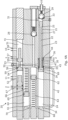
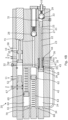
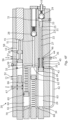
- the pressure-intensifying unit 20 is shown having a first bore 21 and a piston unit 22.
- the first bore 21 has a first bore part 23 with a first inner diameter ID 1 and with a first bore end part 81.
- the first bore 21 also has a second bore part 24 with a second inner diameter ID 2 and with a second bore end part 82.
- the piston unit 22 has a first piston 25 with a first outer diameter OD 1 corresponding to the first inner diameter ID 1 and a second piston 26 with a second outer diameter OD 2 corresponding to the second inner diameter ID 2 .
- the second piston 26 is connected to the first piston 25 by means of a connecting rod 27, which connecting rod 27 has a smaller outer diameter than the second piston 26.
- the first outer diameter OD 1 is smaller than the second outer diameter OD 2 .
- the piston unit 22 moves between a first position in which the first piston 25 is closer to the first bore end part 81 than the second bore part 24 and a second position in which the first piston 25 is closer to the second bore part 24 than the first bore end part 81.
- the first bore part 23 has a first opening 31 in fluid communication with the expansion opening 11 through a first fluid channel 41, and a first non-return valve 28 is arranged in the first fluid channel 41 allowing fluid to enter the first opening 31.
- the second bore part 24 has a second opening 36, and the second opening 36 is closer to the first bore part 23 than the second bore end part 82.
- the first bore part 23 has a third opening 33 in fluid communication with the expandable space 10 through a second non-return valve 29.
- the second bore part 24 has a fourth opening 34 for the entry of fluid in order to allow the first piston 25 to move in a first direction, ejecting fluid through the third opening 33 and into the expandable space 10, and for the exit of fluid in order to allow the first piston 25 to move in a second direction opposite the first direction.
- the pressure-intensifying unit 20 further comprises a sequence piston 30 having a first sequence position in which the sequence piston 30 allows fluid communication between the second opening 36 and the fourth opening 34 and a second sequence position in which the sequence piston 30 allows fluid communication between the second opening 36 and the fourth opening 34 in order to move the piston unit 22 in the first direction.
- the first piston 25 has a front face facing the first bore end part 81.
- the first position As shown in Fig. 2A , most of the fluid in the first bore part 23 in front of the first piston 25 has entered the expandable space 10, and in the second position the first bore part 23 is filled with fluid in front of the first piston.
- the low pressure in the chamber 80 is used to retract the piston unit 22 so that the first bore part 23 in front of the first piston 25 is re-filled with fluid from the annulus 2 or the bore 37.
- the chamber 80 receives the fluid on the back of the first piston 25.
- the annular barrier 1 further comprises a shear element valve block 130 which is fluidly connecting and disconnecting the pressure-intensifying unit 20 with the expandable space 10.
- the shear element valve block 130 is arranged for blocking the fluid communication to the expandable space after the expansion of the annular barrier is finished.
- the second opening 36 is blocked by a shear disc 83 for closing the chamber 80 while the annular barrier 1 is run in hole.
- the shear disc 83 is based on absolute pressure.
- the second opening 36 is blocked by a mechanical connection 84 for closing the chamber 80 while the annular barrier 1 is run in hole.
- the mechanical connection 84 is activated to open by means of a tool run into the well tubular metal structure 3.
- the mechanical connection 84 such as a sleeve or a valve assembly having a breakable pin, and the mechanical connection 84 is activated to open by means of a timer or a tool run into the well tubular metal structure 3.
- the first outer diameter OD 1 is smaller than the second outer diameter OD 2 , as a result of which the fluid having entered through the expansion opening 11 is pressure-intensified before entering the expandable space 10 to expand the expandable metal sleeve 8 of the annular barrier 1 to obtain a higher pressure than the pressure of the fluid entering the expansion opening 11 in the tubular metal part 7 due to the diameter difference between the first piston 25 and the second piston 26.
- the first bore part 23 has the first opening 31 in fluid connection with the expansion opening 11 through the first fluid channel 41, and the first non-return valve 28 is arranged in the first fluid channel 41, allowing fluid to enter the first opening 31.
- the first bore 21 has a sixth opening 32 fluidly connected with a part of the first fluid channel 41 upstream of the first non-return valve 28.
- the first bore part 23 has the third opening 33 in fluid communication with the expandable space 10 through the second non-return valve 29.
- the second bore part 24 has the fourth opening 34 for the entry of fluid in order to allow the first piston 25 to move in a first direction, ejecting fluid through the third opening 33 and into the expandable space 10, and for the exit of fluid in order to allow the first piston 25 to move in a second direction opposite the first direction.
- the second bore part 24 has a fifth opening 35 in fluid communication with the fourth opening 34 through a second fluid channel 42 for allowing fluid to pass from one side of the second piston 26 to the other side of the second piston 26 when the second piston 26 moves back and forth.
- the second fluid channel 42 functions as a kind of bypass channel so that the second piston 26 is able to move as the fluid is in liquid form downhole and thus more or less incompressible and needs to be displaced elsewhere in order to be able to move the second piston 26.
- the pressure-intensifying unit 20 further comprises the sequence piston 30 surrounding the connecting rod 27.
- the sequence piston 30 has a first sequence position in which the sequence piston 30 prevents fluid communication between the sixth opening 32 and the fifth opening 35 so that the fluid from within the tubular metal part 7 passes through the expansion opening 11 and into the first fluid channel 41 through the first non-return valve 28 and in through the first opening 31, and presses onto the first piston 25 to move the first piston 25 in a second direction towards the second bore part 24.
- the sequence piston 30 has a first sequence position in which the sequence piston 30 prevents fluid communication between the sixth opening 32 and the fifth opening 35 so that the fluid from within the tubular metal part 7 passes through the expansion opening 11 and into the first fluid channel 41 through the first non-return valve 28 and in through the first opening 31, and presses onto the first piston 25 to move the first piston 25 in a second direction towards the second bore part 24.
- the sequence piston 30 has a second sequence position in which the sequence piston 30 allows fluid communication between the sixth opening 32 and the fifth opening 35 in order to move the piston unit 22 in the first direction and press the fluid in the first bore part 23 in through the third opening 33 and the second non-return valve 29, and into the expandable space 10 to expand the expandable metal sleeve 8 of the annular barrier 1.
- the sequence piston 30 straddles the sixth opening 32 and the fifth opening 35.
- the sequence piston 30 isolates the sixth opening 32 so that all fluid through the expansion opening 11 is forced to flow in through the first fluid channel 41 and the first non-return valve 28 and into the first bore part 23.
- the sequence piston 30 has a first piston part 43 and a second piston part 44, and an intermediate piston part 45 connecting the first piston part 43 and the second piston part 44;
- the intermediate piston part 45 has a smaller outer diameter than that of the first piston part 43 and the second piston part 44 so as to fluidly connect the sixth opening 32 and the fifth opening 35 when the sequence piston 30 is in the second sequence position, and so that the first piston part 43 is positioned on one side of the fifth opening 35, and the intermediate piston part 45 straddles the sixth opening 32 and the fifth opening 35, and the second piston part 44 is arranged on the other side of the sixth opening 32.
- the intermediate piston part 45 has a smaller outer diameter than that of the first piston part 43 and the second piston part 44, providing an annular cavity 47 between the first bore 21 and the sequence piston 30 to enable fluid passage between the sixth opening 32 and the fifth opening 35.
- the sequence piston 30 has a through-bore 46 having a bore diameter ID 3 being larger than the outer diameter of the connecting rod 27 so that fluid is allowed to pass between the connecting rod 27 and the sequence piston 30 along the bore diameter ID B .
- the outer diameter of the first piston part 43 and the second piston part 44 of the sequence piston 30 corresponds to the inner diameter of the second bore part 24.
- the sequence piston 30 is arranged in the first bore part 23.
- the first bore 21 comprises the second opening 36 arranged between the fifth opening 35 and the third opening 33 and is in fluid communication with a chamber 80. In that way, the chamber pressure is used as an accumulator.
- the first piston part 43 of the sequence piston 30 is provided with at least two sealing elements 72 arranged at a distance between them that is larger than the diameter of the fifth opening 35.
- the second piston part 44 of the sequence piston 30 is sealing off the fifth opening 35 until the sequence piston 30 straddles the fifth opening 35 and the second opening 36, and there is no risk of stranding opposite the fifth opening 35, where fluid may flow from the second opening 36 past the first piston part 43 and directly into the second bore part 24 without being forced through the second fluid channel 42, as shown in Fig. 4C .
- the outer diameter of the connecting rod 27 is smaller than the first outer diameter OD 1 and the second outer diameter OD 2 .
- the outer diameter of the connecting rod 27 is smaller than the first outer diameter OD 1 and substantially equal to the second outer diameter OD 2 .
- the sequence piston 30 has an internal key 73 moving in a groove 74 of the connecting rod 27 for bringing the sequence piston 30 to move from the first sequence position to the second sequence position. The movement of the sequence piston 30 from the second sequence position to the first sequence position is performed by the second piston 26.
- the second outer diameter OD 2 is more than 1.2 times larger than the first outer diameter OD 1 , preferably more than 1.5 times larger than the first outer diameter, more preferably more than 2 times larger than the first outer diameter, and even more preferably more than 2.5 times larger than the first outer diameter.
- the pressure intensification factor of the pressure-intensifying unit 20 is given by the piston area difference between the first and the second piston 25, 26, and thus the difference between the second outer diameter OD 2 and the first outer diameter OD 1 is (OD 2 /OD 1 ) ⁇ 2.
- the second bore 51 is arranged in parallel to the first bore 21, but could be arranged in any angle to the first bore 21.
- the third piston 54 and the fourth piston 55 are prevented from moving in the deployment position by a shear pin 59 until the expansion operation starts and a pressure builds up inside the tubular metal part 7; when a predetermined pressure is obtained in the well tubular metal structure 3 acting on the third piston 54, the shear pin 59 is sheared, and the third piston 54 and the fourth piston 55 move, providing fluid communication between the first aperture 52 and the second aperture 53 as well as fluid communication to the first bore 21.
- the shear pin function is arranged in an additional shear pin valve block 130 (shear element valve block 130 shown in Fig. 5 ) in fluid communication with the second aperture 53 and arranged fluidly between the expansion opening 11 and the second aperture 53.
- the shear pin 59 could also be replaced by a shear disc arranged in the fluid communication between the expansion opening 11 and the second aperture 53.
- the second bore 51 further comprises a third aperture 57 in fluid communication with the annulus 2 and a fourth aperture 58 in fluid communication with the expandable space 10, as shown in Fig. 4A .
- the third piston 54 and the fourth piston 55 are both arranged on one side of the third aperture 57 and the fourth aperture 58, providing fluid communication between the third and fourth apertures 57, 58.
- the role of the third piston 54 and the fourth piston 55 is also to ensure that there is no trapped pressure in the annular barrier 1, i.e.
- the third aperture 57 and the fourth aperture 58 are in fluid communication on the "backside” of the third piston 54 and the fourth piston 55 as the second aperture 53 is arranged on the "frontside” of the third piston 54 and the fourth piston 55, while the third piston 54 and the fourth piston 55 are arranged on either side of the second aperture 53.
- the first chamber 61 is able to accumulate fluid in the second bore part 24 which cannot bypass the second piston 26 in the second fluid channel 42 when the second piston 26 moves in the second direction. This is primarily the situation which may occur towards the end of the movement in the second direction as shown in Fig. 4C , where the first piston 25 moves the sequence piston 30, blocking the fifth opening 35 even though the second piston 26 has not moved entirely to the end (as shown in Fig. 4D ), and the remaining fluid can then enter the first chamber 61.
- the first chamber is thus a safety precaution to ensure that the sequence piston 30 is able to move to the second sequence position.
- the first chamber piston 62 is preloaded by the pressure in the expansion fluid pressing through the second chamber opening 69 and on the first chamber piston 62.
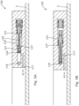
- Figs. 5A and 5B disclose a shear element valve block 130 having a first block opening 116 in fluid communication with the expansion opening 11 and a block piston 121 moving in a bore 120 and having a through-bore 122 in which a shear disc 124 is arranged.
- a second block opening 117 is in fluid communication with the first fluid channel 41 in Figs. 2A-4F so that, in the first block position shown in Fig. 5A , fluid from the expansion opening 11 is let into the pressure-intensifying unit 20, and in a second block position, as shown in Fig. 5B , the shear element valve block 130 prevents the fluid from entering since the fluid communication between the first block opening 116 and the second block opening 117 is blocked.
- the annular barrier 1 may be part of a downhole system 100 as shown in Fig. 1 , where the downhole system comprises a well tubular metal structure 3 and the above-mentioned annular barrier, and where the tubular metal part 7 is mounted as part of the well tubular metal structure 3.
- the downhole system 100 may have a plurality of annular barriers even though not shown.
- fluid or "well fluid” is meant any kind of fluid that may be present in oil or gas wells downhole, such as natural gas, oil, oil mud, crude oil, water, etc.
- gas is meant any kind of gas composition present in a well, completion or open hole, and by “oil” is meant any kind of oil composition, such as crude oil, an oil-containing fluid, etc.
- Oil and water fluids may thus all comprise other elements or substances than gas, oil and/or water, respectively.
- a downhole tractor can be used to push the tool all the way into position in the well.
- the downhole tractor may have projectable arms having wheels, wherein the wheels contact the inner surface of the casing for propelling the tractor and the tool forward in the casing.
- a downhole tractor is any kind of driving tool capable of pushing or pulling tools in a well downhole, such as a Well Tractor ® .
Landscapes
- Life Sciences & Earth Sciences (AREA)
- Engineering & Computer Science (AREA)
- Geology (AREA)
- Mining & Mineral Resources (AREA)
- Physics & Mathematics (AREA)
- Environmental & Geological Engineering (AREA)
- Fluid Mechanics (AREA)
- General Life Sciences & Earth Sciences (AREA)
- Geochemistry & Mineralogy (AREA)
- Pistons, Piston Rings, And Cylinders (AREA)
Priority Applications (4)
| Application Number | Priority Date | Filing Date | Title |
|---|---|---|---|
| EP23196510.4A EP4520915A1 (fr) | 2023-09-11 | 2023-09-11 | Barrière annulaire et système de fond de trou |
| AU2024335607A AU2024335607A1 (en) | 2023-09-08 | 2024-09-09 | Annular barrier and downhole system |
| US18/828,816 US12486737B2 (en) | 2023-09-08 | 2024-09-09 | Annular barrier and downhole system |
| PCT/EP2024/075118 WO2025051999A1 (fr) | 2023-09-08 | 2024-09-09 | Barrière annulaire et système de fond de trou |
Applications Claiming Priority (1)
| Application Number | Priority Date | Filing Date | Title |
|---|---|---|---|
| EP23196510.4A EP4520915A1 (fr) | 2023-09-11 | 2023-09-11 | Barrière annulaire et système de fond de trou |
Publications (1)
| Publication Number | Publication Date |
|---|---|
| EP4520915A1 true EP4520915A1 (fr) | 2025-03-12 |
Family
ID=88017995
Family Applications (1)
| Application Number | Title | Priority Date | Filing Date |
|---|---|---|---|
| EP23196510.4A Withdrawn EP4520915A1 (fr) | 2023-09-08 | 2023-09-11 | Barrière annulaire et système de fond de trou |
Country Status (1)
| Country | Link |
|---|---|
| EP (1) | EP4520915A1 (fr) |
Citations (2)
| Publication number | Priority date | Publication date | Assignee | Title |
|---|---|---|---|---|
| EP2570588A1 (fr) * | 2011-09-13 | 2013-03-20 | Welltec A/S | Barrière annulaire dotée d'un mécanisme de force axiale |
| WO2022069547A1 (fr) * | 2020-09-30 | 2022-04-07 | Welltec Oilfield Solutions Ag | Barrière annulaire avec unité d'intensification de pression |
-
2023
- 2023-09-11 EP EP23196510.4A patent/EP4520915A1/fr not_active Withdrawn
Patent Citations (2)
| Publication number | Priority date | Publication date | Assignee | Title |
|---|---|---|---|---|
| EP2570588A1 (fr) * | 2011-09-13 | 2013-03-20 | Welltec A/S | Barrière annulaire dotée d'un mécanisme de force axiale |
| WO2022069547A1 (fr) * | 2020-09-30 | 2022-04-07 | Welltec Oilfield Solutions Ag | Barrière annulaire avec unité d'intensification de pression |
Similar Documents
| Publication | Publication Date | Title |
|---|---|---|
| US11002098B2 (en) | Downhole patching setting tool | |
| US9725980B2 (en) | Annular barrier with pressure amplification | |
| US8893798B2 (en) | Barrier valve hydraulic operator with compound valve opening force feature | |
| WO2009114371A2 (fr) | Compensateur de pression pour des garnitures d’étanchéité actionnées de manière hydrostatique | |
| EP4222346B1 (fr) | Barrière annulaire dotée d'une unité multiplicatrice de pression | |
| US9347287B2 (en) | Wellbore treatment tool and method | |
| EP3914805B1 (fr) | Système et méthodologie de dispositif de suspension expansible de la colonne perdue | |
| US12196053B2 (en) | Plug and abandonment system | |
| EP4028634B1 (fr) | Système de barrière annulaire | |
| EP4520915A1 (fr) | Barrière annulaire et système de fond de trou | |
| US12486737B2 (en) | Annular barrier and downhole system | |
| RU2065948C1 (ru) | Способ вызова притока из пласта и устройство для его осуществления | |
| US12480378B2 (en) | Annular barrier with valve unit | |
| CN122003539A (zh) | 环空屏障和井下系统 | |
| EP3978722A1 (fr) | Barrière annulaire dotée d'une unité multiplicatrice de pression | |
| EP3526440B1 (fr) | Ensemble expansif | |
| EA046963B1 (ru) | Затрубный барьер с повышающим давление узлом | |
| CN116084904B (zh) | 一种能够多重连锁保护的co2压裂辅助增压装置及方法 | |
| EP3309351A1 (fr) | Ensemble expansif |
Legal Events
| Date | Code | Title | Description |
|---|---|---|---|
| PUAI | Public reference made under article 153(3) epc to a published international application that has entered the european phase |
Free format text: ORIGINAL CODE: 0009012 |
|
| STAA | Information on the status of an ep patent application or granted ep patent |
Free format text: STATUS: THE APPLICATION HAS BEEN PUBLISHED |
|
| AK | Designated contracting states |
Kind code of ref document: A1 Designated state(s): AL AT BE BG CH CY CZ DE DK EE ES FI FR GB GR HR HU IE IS IT LI LT LU LV MC ME MK MT NL NO PL PT RO RS SE SI SK SM TR |
|
| STAA | Information on the status of an ep patent application or granted ep patent |
Free format text: STATUS: THE APPLICATION IS DEEMED TO BE WITHDRAWN |
|
| 18D | Application deemed to be withdrawn |
Effective date: 20250913 |