EP4520960A1 - Outil d'allongement pour allonger une tige filetée ou un boulon d'un raccord à bride - Google Patents
Outil d'allongement pour allonger une tige filetée ou un boulon d'un raccord à bride Download PDFInfo
- Publication number
- EP4520960A1 EP4520960A1 EP23195802.6A EP23195802A EP4520960A1 EP 4520960 A1 EP4520960 A1 EP 4520960A1 EP 23195802 A EP23195802 A EP 23195802A EP 4520960 A1 EP4520960 A1 EP 4520960A1
- Authority
- EP
- European Patent Office
- Prior art keywords
- bolt
- threaded rod
- engagement means
- thread engagement
- elongation tool
- Prior art date
- Legal status (The legal status is an assumption and is not a legal conclusion. Google has not performed a legal analysis and makes no representation as to the accuracy of the status listed.)
- Granted
Links
Images


Classifications
-
- B—PERFORMING OPERATIONS; TRANSPORTING
- B25—HAND TOOLS; PORTABLE POWER-DRIVEN TOOLS; MANIPULATORS
- B25B—TOOLS OR BENCH DEVICES NOT OTHERWISE PROVIDED FOR, FOR FASTENING, CONNECTING, DISENGAGING, OR HOLDING
- B25B29/00—Accessories
- B25B29/02—Bolt tensioners
-
- B—PERFORMING OPERATIONS; TRANSPORTING
- B23—MACHINE TOOLS; METAL-WORKING NOT OTHERWISE PROVIDED FOR
- B23P—METAL-WORKING NOT OTHERWISE PROVIDED FOR; COMBINED OPERATIONS; UNIVERSAL MACHINE TOOLS
- B23P19/00—Machines for simply fitting together or separating metal parts or objects, or metal and non-metal parts, whether or not involving some deformation; Tools or devices therefor so far as not provided for in other classes
- B23P19/04—Machines for simply fitting together or separating metal parts or objects, or metal and non-metal parts, whether or not involving some deformation; Tools or devices therefor so far as not provided for in other classes for assembling or disassembling parts
- B23P19/06—Screw or nut setting or loosening machines
- B23P19/067—Bolt tensioners
-
- F—MECHANICAL ENGINEERING; LIGHTING; HEATING; WEAPONS; BLASTING
- F03—MACHINES OR ENGINES FOR LIQUIDS; WIND, SPRING, OR WEIGHT MOTORS; PRODUCING MECHANICAL POWER OR A REACTIVE PROPULSIVE THRUST, NOT OTHERWISE PROVIDED FOR
- F03D—WIND MOTORS
- F03D13/00—Assembly, mounting or commissioning of wind motors; Arrangements specially adapted for transporting wind motor components
- F03D13/10—Assembly of wind motors; Arrangements for erecting wind motors
- F03D13/112—Assembly of wind motors; Arrangements for erecting wind motors of towers; of masts
-
- F—MECHANICAL ENGINEERING; LIGHTING; HEATING; WEAPONS; BLASTING
- F03—MACHINES OR ENGINES FOR LIQUIDS; WIND, SPRING, OR WEIGHT MOTORS; PRODUCING MECHANICAL POWER OR A REACTIVE PROPULSIVE THRUST, NOT OTHERWISE PROVIDED FOR
- F03D—WIND MOTORS
- F03D13/00—Assembly, mounting or commissioning of wind motors; Arrangements specially adapted for transporting wind motor components
- F03D13/20—Arrangements for mounting or supporting wind motors; Masts or towers for wind motors
- F03D13/201—Towers
- F03D13/205—Connection means, e.g. joints between segments
-
- F—MECHANICAL ENGINEERING; LIGHTING; HEATING; WEAPONS; BLASTING
- F05—INDEXING SCHEMES RELATING TO ENGINES OR PUMPS IN VARIOUS SUBCLASSES OF CLASSES F01-F04
- F05B—INDEXING SCHEME RELATING TO WIND, SPRING, WEIGHT, INERTIA OR LIKE MOTORS, TO MACHINES OR ENGINES FOR LIQUIDS COVERED BY SUBCLASSES F03B, F03D AND F03G
- F05B2260/00—Function
- F05B2260/30—Retaining components in desired mutual position
- F05B2260/301—Retaining bolts or nuts
Definitions
- the rotational movement of the threaded rod or bolt is arrested, and therefore the thread engagement means may be screwed onto the threaded rod or bolt, without the risk of loosening the pre tightened bolt connection, or the risk of misaligning the thread engagement means.
- the elongation tool according to the invention therefore reduces risk of bolts rotating. In addition, it reduces the need of or the amount of snug tightening of the bolts prior to commencement of the elongation tool tightening process.
- the friction means comprise a push element configured to apply a second force to the threaded rod or bolt directed essentially perpendicular to and in direction towards the flange connection.
- the fri force may be increased.
- the push element is arranged essentially in line with the thread engagement means and configured to apply the second force in line with and in direction towards the thread engagement means. This leads to an even higher friction being generated.
- the push element comprises a contact surface for interacting with the threaded rod or bolt, wherein the contact surface comprises a friction enhancing material. This also leads to an increased friction between the threaded rod or bolt and the friction means.
- the friction means may comprise a clamping unit configured to apply a clamping force to the threaded rod or bolt, when the thread engagement means are being threaded onto the threaded rod or bolt.
- a clamping unit configured to apply a clamping force to the threaded rod or bolt, when the thread engagement means are being threaded onto the threaded rod or bolt.
- the clamping unit may clamp the threaded rod or bolt along a circumference of the threaded rod or bolt ensuring an even contact surface between the threaded rod or bolt and the friction means.
- the friction means comprise a push element configured to apply a third force to the threaded rod or bolt directed essentially perpendicular to the length of the threaded rod or bolt.
- the threaded rod or bolt may be forced into contact with an inner wall of a through hole of the flange connection, further increasing the friction forces available to counteract the turning of the threaded rod or bolt.
- the lowering unit comprises a linear motor.
- the lowering unit may also be realized by a mechanical arm connected to a series of gears or chain drives.
- Other mechanical means of realizing a lowering unit are obvious to the person skilled in the art. These options provide robust and stable means of propulsion.
- the elongation tool according to the invention also preferably comprises a drive unit configured to move the elongation tool along the flange connection.
- a drive unit configured to move the elongation tool along the flange connection.
- the elongation tool according to the invention preferably comprises a centering unit, which is configured to align a central axis of the thread engagement means with a central axis of the threaded rod or bolt. This prevents the thread engagement means from being cross threaded onto the threaded rod or bolt.
- the expansion device of the elongation unit may comprise a hydraulic cylinder.
- the hydraulic cylinder provides the advantage of providing considerable force while still maintaining small external dimensions.
- the elongation tool according to the invention may also comprise a lock nut fastening device, which is configured to fasten a lock nut screwed on the threaded rod or bolt, while the expansion device is exerting the first force onto the thread engagement means.
- a lock nut fastening device configured to fasten a lock nut screwed on the threaded rod or bolt, while the expansion device is exerting the first force onto the thread engagement means.
- the elongation tool 1 for elongating a threaded rod or a bolt 2 of a flange connection 3 is shown in a preferred embodiment in figure 1 in a frontal view.
- the flange connection 3 is held together by a series of threaded rods or bolts 2, wherein on each threaded rod upper and lower lock nuts 4 are fastened in order to achieve a predefined clamping force.
- a bolt head is arranged at the position pf the lower lock nut 4, as can be seen in figure 3 , and only an upper lock nut 4 is used.
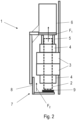
- the lower lock nut 4 of the bolt 2 is visible in figure 2 .
- the elongation tool 1 comprises a rotatable thread engagement means 5 and an expansion device 6, wherein the thread engagement means 5 are configured to be threaded onto the threaded rod or bolt 2.
- the thread engagement means 5 are not engaged with the threads of a threaded rod or bolt 2, wherein in figure 2 and figure 3 the thread engagement means 5 are engaged with the threads of the threaded rod or bolt 2.
- the expansion device 6 is connected to the thread engagement means 5 and configured to exert a first force F 1 essentially perpendicular to and away from the flange connection 3 onto the thread engagement means 5, when the thread engagement means 5 are engaged with a thread of the threaded rod or bolt 2.
- the expansion device 6 comprises, according to the preferred embodiment of the elongation tool 1, a hydraulic cylinder.
- the hydraulic cylinder provides the advantage of providing considerable force while still maintaining small external dimensions.
- the elongation tool 1 furthermore comprises friction means 7 configured to be brought into contact with the threaded rod or bolt 2 and provide friction between the friction means 7 and the threaded rod or bolt 2 when the thread engagement means 5 are threaded onto the threaded rod or bolt 2, and to arrest a rotational movement of the threaded rod or bolt 2.
- the friction means 8 can be connected to a cart or a robot, that carries the elongation tool 1 along the flange connection 4 and/or connected to any other suitable component of the elongation tool 1.
- the friction means 7 are not visible in detail, as they are shown from a rear view.
- Figure 2 shows a schematic side view of the elongation tool 1 according to the invention, where the friction means 7 are visible in greater detail.
- the push element 8 is preferably arranged essentially in line with the thread engagement means 5 and configured to apply the second force F 2 in line with and in direction towards the thread engagement means 5. This reduces the risk of misaligning the threaded rod or bolt 2 and the thread engagement means 5.
- the friction means 7 prevents or reduces risk of rotation of the threaded rod or bolt 2 due to the force F 2 being applied between the friction means 7 and either the bolt head, as seen in figure 3 or the threaded rod as seen in figure 2 .
- the coupling unit 9 preferably also comprises a height compensation unit 12 shown in figure 1 , which is configured to support the thread engagement means 5.
- the height compensation unit 12 comprises a free play along a lowering direction LD of the lowering unit 10, and the thread engagement means 5 are displaceable along the free play of the height compensation unit 12, when the thread engagement means 5 are supported by the height compensation unit 12.
- the thread engagement means 5 may contact the threaded rod or bolt 2 on its upper end, oriented away from the flange connection 3, without being forced by the lowering unit 10 onto the thread of the threaded rod or bolt 2 immediately.
- the thread engagement means 5 can be rotated a certain degree while resting on the threaded rod or bolt 2, so that the threads of the threaded rod or bolt 2 and the threads of the thread engagement means 5 are aligned. This reduces the stress on the first thread of the threaded rod or bolt 2 greatly and reduces the risk of damaging the thread engagement means 5 or the threaded rod or bolt 2.
- the free play may be for example 8 mm, while usually 4 mm of this free play is used when the thread engagement means 5 are engaging the thread of the threaded rod or bolt 2.
- the height compensation unit 12 may also comprise a free play measuring device, which is not shown in the figures, configured to stop or reduce a lowering speed of the lowering unit 10 once the thread engagement means 5 have been displaced for a predetermined distance along the free play.
- a free play measuring device configured to stop or reduce a lowering speed of the lowering unit 10 once the thread engagement means 5 have been displaced for a predetermined distance along the free play.
- the elongation tool 1 preferably also comprises a drive unit 13 configured to move the elongation tool 1 along the flange connection 3.
- the preferred embodiment of the elongation tool 1 depicted in the figures comprises two drive units 13.
- the drive unit 13 may for example include a chain drive or a wheel drive. Other means of propulsion applicable to the drive unit 13 are generally known to the person skilled in the art.
- the drive unit 13 enables the elongation tool 1 according to the invention to operate autonomously and automatically place the elongation tool 1 above the threaded rods or bolts 2 to fasten a series of lock nuts 4 of the flange connection 3.
- the elongation tool 1 also comprises a centering unit, which is not shown in the figures, and which is configured to align a central axis of the thread engagement means 5 with a central axis of the threaded rod or bolt 2.
- a centering unit which is not shown in the figures, and which is configured to align a central axis of the thread engagement means 5 with a central axis of the threaded rod or bolt 2.
- the bolt elongation tool 1 may preferably comprise a lock nut fastening device 14, which is shown in figure 1 and is configured to fasten a lock nut 4 screwed on the threaded rod or bolt 2, while the expansion device 5 is exerting the force F 1 onto the thread engagement means 5.
- the elongation tool 1 according to the invention can be used to simultaneously elongate the threaded rod or bolt 2 and fixate the threaded rod or bolt 2 with the lock nut 4.
Landscapes
- Engineering & Computer Science (AREA)
- Mechanical Engineering (AREA)
- Hand Tools For Fitting Together And Separating, Or Other Hand Tools (AREA)
- Mutual Connection Of Rods And Tubes (AREA)
Priority Applications (3)
| Application Number | Priority Date | Filing Date | Title |
|---|---|---|---|
| EP23195802.6A EP4520960B1 (fr) | 2023-09-06 | 2023-09-06 | Outil d'allongement pour allonger une tige filetée ou un boulon d'un raccord à bride |
| PCT/EP2024/074163 WO2025051623A1 (fr) | 2023-09-06 | 2024-08-29 | Outil d'allongement permettant d'allonger une tige filetée ou un boulon d'un raccord à bride |
| CN202480057059.6A CN121794467A (zh) | 2023-09-06 | 2024-08-29 | 用于使法兰连接的螺纹杆或螺栓伸长的伸长工具 |
Applications Claiming Priority (1)
| Application Number | Priority Date | Filing Date | Title |
|---|---|---|---|
| EP23195802.6A EP4520960B1 (fr) | 2023-09-06 | 2023-09-06 | Outil d'allongement pour allonger une tige filetée ou un boulon d'un raccord à bride |
Publications (3)
| Publication Number | Publication Date |
|---|---|
| EP4520960A1 true EP4520960A1 (fr) | 2025-03-12 |
| EP4520960B1 EP4520960B1 (fr) | 2026-02-18 |
| EP4520960C0 EP4520960C0 (fr) | 2026-02-18 |
Family
ID=87933865
Family Applications (1)
| Application Number | Title | Priority Date | Filing Date |
|---|---|---|---|
| EP23195802.6A Active EP4520960B1 (fr) | 2023-09-06 | 2023-09-06 | Outil d'allongement pour allonger une tige filetée ou un boulon d'un raccord à bride |
Country Status (3)
| Country | Link |
|---|---|
| EP (1) | EP4520960B1 (fr) |
| CN (1) | CN121794467A (fr) |
| WO (1) | WO2025051623A1 (fr) |
Citations (3)
| Publication number | Priority date | Publication date | Assignee | Title |
|---|---|---|---|---|
| US20180333812A1 (en) * | 2017-05-17 | 2018-11-22 | General Electric Company | Turbomachine service apparatus and related method |
| US20190299344A1 (en) * | 2018-03-29 | 2019-10-03 | Jörg Hohmann | Device for Tightening Screw Connections |
| US11148240B2 (en) * | 2018-03-29 | 2021-10-19 | Jörg Hohmann | Device for tightening screw connections |
-
2023
- 2023-09-06 EP EP23195802.6A patent/EP4520960B1/fr active Active
-
2024
- 2024-08-29 WO PCT/EP2024/074163 patent/WO2025051623A1/fr active Pending
- 2024-08-29 CN CN202480057059.6A patent/CN121794467A/zh active Pending
Patent Citations (3)
| Publication number | Priority date | Publication date | Assignee | Title |
|---|---|---|---|---|
| US20180333812A1 (en) * | 2017-05-17 | 2018-11-22 | General Electric Company | Turbomachine service apparatus and related method |
| US20190299344A1 (en) * | 2018-03-29 | 2019-10-03 | Jörg Hohmann | Device for Tightening Screw Connections |
| US11148240B2 (en) * | 2018-03-29 | 2021-10-19 | Jörg Hohmann | Device for tightening screw connections |
Also Published As
| Publication number | Publication date |
|---|---|
| EP4520960B1 (fr) | 2026-02-18 |
| CN121794467A (zh) | 2026-04-03 |
| WO2025051623A1 (fr) | 2025-03-13 |
| EP4520960C0 (fr) | 2026-02-18 |
Similar Documents
| Publication | Publication Date | Title |
|---|---|---|
| EP3195991B1 (fr) | Robot avec moyen de positionnement pour déplacer un outil le long d'un joint à brides | |
| US10702960B2 (en) | Robot to move a support platform along a flange connection | |
| KR101958676B1 (ko) | 풍력 터빈용 볼트 조임 로봇 | |
| CN115122081B (zh) | 拧紧装置 | |
| EP4520960B1 (fr) | Outil d'allongement pour allonger une tige filetée ou un boulon d'un raccord à bride | |
| CN114888553B (zh) | 导轨式风电机组塔筒内法兰连接螺栓紧固装置及工作方法 | |
| CN106239118B (zh) | 拉轴拧紧设备 | |
| CN115971867A (zh) | 一种螺栓拆卸装置 | |
| US12304018B2 (en) | Coupling unit for coupling a rotatable thread engagement means of a bolt elongation tool for elongating a bolt of a flange connection with the bolt | |
| EP2485871A1 (fr) | Outil de montage de goujons | |
| CN120055776A (zh) | 一种舵杆螺母安装装置及其安装方法 | |
| CN219704087U (zh) | 一种螺栓拆卸装置 | |
| CN216098646U (zh) | 一种应用扭矩差值传动机构的电动扳手 | |
| CN223947784U (zh) | 一种过盈螺桩安装工装 | |
| CN217603133U (zh) | 一种摩托车用自锁式抗震螺栓 | |
| CN220539770U (zh) | 一种在线监测风力发电机变桨轴承螺栓装置 | |
| CN222750006U (zh) | 一种风力发电塔电缆固定装置 | |
| CN219341356U (zh) | 一种限速器绳伸缩调节装置 | |
| CN220218359U (zh) | 一种抽油机平衡块螺帽松卸装置 | |
| CN220056028U (zh) | 一种装配式楼梯段的吊装卡具 | |
| CA3011908C (fr) | Robot pour deplacer une plate-forme de support le long d'un raccordement de bride | |
| CN211759737U (zh) | 风电叶片法兰孔错位的塔上校正装置 | |
| CN211940755U (zh) | 一种双头螺栓螺纹工件拧紧装置 | |
| CN211229738U (zh) | 一种输电线杆塔抱杆安装固定装置 | |
| CN121514874A (zh) | 一种简统化腕臂智能维修机器人 |
Legal Events
| Date | Code | Title | Description |
|---|---|---|---|
| PUAI | Public reference made under article 153(3) epc to a published international application that has entered the european phase |
Free format text: ORIGINAL CODE: 0009012 |
|
| STAA | Information on the status of an ep patent application or granted ep patent |
Free format text: STATUS: REQUEST FOR EXAMINATION WAS MADE |
|
| 17P | Request for examination filed |
Effective date: 20240219 |
|
| AK | Designated contracting states |
Kind code of ref document: A1 Designated state(s): AL AT BE BG CH CY CZ DE DK EE ES FI FR GB GR HR HU IE IS IT LI LT LU LV MC ME MK MT NL NO PL PT RO RS SE SI SK SM TR |
|
| GRAP | Despatch of communication of intention to grant a patent |
Free format text: ORIGINAL CODE: EPIDOSNIGR1 |
|
| STAA | Information on the status of an ep patent application or granted ep patent |
Free format text: STATUS: GRANT OF PATENT IS INTENDED |
|
| INTG | Intention to grant announced |
Effective date: 20250912 |
|
| GRAS | Grant fee paid |
Free format text: ORIGINAL CODE: EPIDOSNIGR3 |
|
| GRAL | Information related to payment of fee for publishing/printing deleted |
Free format text: ORIGINAL CODE: EPIDOSDIGR3 |
|
| GRAS | Grant fee paid |
Free format text: ORIGINAL CODE: EPIDOSNIGR3 |
|
| GRAA | (expected) grant |
Free format text: ORIGINAL CODE: 0009210 |
|
| STAA | Information on the status of an ep patent application or granted ep patent |
Free format text: STATUS: THE PATENT HAS BEEN GRANTED |
|
| AK | Designated contracting states |
Kind code of ref document: B1 Designated state(s): AL AT BE BG CH CY CZ DE DK EE ES FI FR GB GR HR HU IE IS IT LI LT LU LV MC ME MK MT NL NO PL PT RO RS SE SI SK SM TR |
|
| REG | Reference to a national code |
Ref country code: CH Ref legal event code: F10 Free format text: ST27 STATUS EVENT CODE: U-0-0-F10-F00 (AS PROVIDED BY THE NATIONAL OFFICE) Effective date: 20260218 Ref country code: GB Ref legal event code: FG4D |
|
| REG | Reference to a national code |
Ref country code: IE Ref legal event code: FG4D |
|
| U01 | Request for unitary effect filed |
Effective date: 20260223 |
|
| U07 | Unitary effect registered |
Designated state(s): AT BE BG DE DK EE FI FR IT LT LU LV MT NL PT RO SE SI Effective date: 20260226 |