EP4520962A1 - Éolienne - Google Patents
Éolienne Download PDFInfo
- Publication number
- EP4520962A1 EP4520962A1 EP23195595.6A EP23195595A EP4520962A1 EP 4520962 A1 EP4520962 A1 EP 4520962A1 EP 23195595 A EP23195595 A EP 23195595A EP 4520962 A1 EP4520962 A1 EP 4520962A1
- Authority
- EP
- European Patent Office
- Prior art keywords
- energy storage
- storage unit
- main shaft
- wind turbine
- energy
- Prior art date
- Legal status (The legal status is an assumption and is not a legal conclusion. Google has not performed a legal analysis and makes no representation as to the accuracy of the status listed.)
- Withdrawn
Links
Images


Classifications
-
- F—MECHANICAL ENGINEERING; LIGHTING; HEATING; WEAPONS; BLASTING
- F03—MACHINES OR ENGINES FOR LIQUIDS; WIND, SPRING, OR WEIGHT MOTORS; PRODUCING MECHANICAL POWER OR A REACTIVE PROPULSIVE THRUST, NOT OTHERWISE PROVIDED FOR
- F03D—WIND MOTORS
- F03D80/00—Details, components or accessories not provided for in groups F03D1/00 - F03D17/00
- F03D80/003—Power-supply to auxiliary components, e.g. to pitch drives or cooling fans
-
- F—MECHANICAL ENGINEERING; LIGHTING; HEATING; WEAPONS; BLASTING
- F03—MACHINES OR ENGINES FOR LIQUIDS; WIND, SPRING, OR WEIGHT MOTORS; PRODUCING MECHANICAL POWER OR A REACTIVE PROPULSIVE THRUST, NOT OTHERWISE PROVIDED FOR
- F03D—WIND MOTORS
- F03D1/00—Wind motors with rotation axis substantially parallel to the air flow entering the rotor
- F03D1/06—Rotors
- F03D1/065—Rotors characterised by their construction elements
- F03D1/0658—Arrangements for fixing wind-engaging parts to a hub
- F03D1/0662—Arrangements for fixing wind-engaging parts to a hub using kinematic linkage, e.g. tilt
- F03D1/0664—Pitch arrangements
- F03D1/0667—Pitch arrangements characterized by the actuator arrangements
-
- F—MECHANICAL ENGINEERING; LIGHTING; HEATING; WEAPONS; BLASTING
- F05—INDEXING SCHEMES RELATING TO ENGINES OR PUMPS IN VARIOUS SUBCLASSES OF CLASSES F01-F04
- F05B—INDEXING SCHEME RELATING TO WIND, SPRING, WEIGHT, INERTIA OR LIKE MOTORS, TO MACHINES OR ENGINES FOR LIQUIDS COVERED BY SUBCLASSES F03B, F03D AND F03G
- F05B2240/00—Components
- F05B2240/60—Shafts
- F05B2240/61—Shafts hollow
-
- Y—GENERAL TAGGING OF NEW TECHNOLOGICAL DEVELOPMENTS; GENERAL TAGGING OF CROSS-SECTIONAL TECHNOLOGIES SPANNING OVER SEVERAL SECTIONS OF THE IPC; TECHNICAL SUBJECTS COVERED BY FORMER USPC CROSS-REFERENCE ART COLLECTIONS [XRACs] AND DIGESTS
- Y02—TECHNOLOGIES OR APPLICATIONS FOR MITIGATION OR ADAPTATION AGAINST CLIMATE CHANGE
- Y02E—REDUCTION OF GREENHOUSE GAS [GHG] EMISSIONS, RELATED TO ENERGY GENERATION, TRANSMISSION OR DISTRIBUTION
- Y02E10/00—Energy generation through renewable energy sources
- Y02E10/70—Wind energy
- Y02E10/72—Wind turbines with rotation axis in wind direction
Definitions
- the present invention relates to a wind turbine.
- Modern wind turbines usually have rotor blades with adjustable pitch angle.
- the rotor blades can be rotated about their longitudinal axis by means of a pitch drive.
- the pitch drive allows to move the blades into feather position and, thus, to aerodynamically brake the rotor.
- the aerodynamical braking of the rotor blades is also used in case of an emergency.
- Such an emergency includes, for example, a failure of the drive train of the wind turbine or a damaged and/or uncontrolled state of the wind turbine, e.g., due to lightning.
- the pitch drive is required to function even in an emergency case.
- the wind turbine comprises:
- the at least one pitch drive and the at least one energy storage unit for supplying energy to the at least one pitch drive are part of a pitch system of the wind turbine for adjusting the pitch angle of the at least one blade.
- the pitch system of the wind turbine is used for optimizing the rotor speed and the power generation of the wind turbine during normal conditions. Furthermore, the pitch system is also used for aerodynamically braking the at least one rotor blade in case of an emergency such as a failure of the drive train of the wind turbine or a damaged/uncontrolled state of the wind turbine, e.g., due to lightning.
- the at least one energy storage unit By arranging the at least one energy storage unit in the cavity of the main shaft, the at least one energy storage unit is arranged close to the at least one blade and close to the pitch drive.
- the at least one pitch drive can be supplied with energy (e.g., hydraulic or electric energy) even in a case in which an energy supply from the stationary part of the nacelle is interrupted and/or not possible.
- energy e.g., hydraulic or electric energy
- the at least one energy storage unit is rotating together with the main shaft and the rotor.
- energy supplied from the at least one energy storage unit to the at least one pitch drive does not have to be transported from a rotating part to a stationary part of the wind turbine.
- a risk of interruption of energy supply e.g., by tearing off an energy supply line
- the rotor and the main shaft are regarded as rotating part.
- the stationary part of the nacelle such as a bed plate and a housing of the nacelle, are regarded as the stationary part being stationary with respect to said rotating part.
- the hub can be configured smaller. Therefore, the hub can be easier transported, e.g., to an erection site of the wind turbine. Further, regulations with respect to a limited transportation size of a wind turbine hub (e.g., a limited height and width of the hub during transport) can be easier fulfilled.
- blade bearings In particular, longer and heavier blades require an increased capacity of blade bearings.
- the capacity of blade bearings can be increased, for example, by increasing the height of the blade bearing and/or stiffening the structural hub. However, these measures tend to reduce interior space in the hub.
- the wind turbine is an apparatus to convert the wind's kinetic energy into electrical energy.
- the wind turbine comprises the rotor having a hub and one or more blades each connected to the hub.
- the rotor is configured to be driven by wind to rotate.
- the wind turbine further comprises a nacelle accommodating the generator.
- the generator is configured to convert the rotational energy into electrical energy.
- the wind turbine optionally comprises a gear box arranged inside the nacelle.
- the wind turbine further comprises a tower holding, at its top end, the nacelle.
- the tower of the wind turbine is mechanically connected to a foundation fixed to the ground or seabed.
- the main shaft is a rotating shaft.
- the main shaft is, in particular, a low-speed rotating shaft.
- the main shaft rotates, for example, with the same rotational speed as the rotor.
- the main shaft connects the rotor hub to the gear box and/or the generator.
- the main shaft is configured to transmit the rotation of the rotor either directly to the generator (gearless wind turbine) or to transmit it via the gear box and a further rotating shaft (high-speed rotating shaft) to the generator (geared wind turbine).
- the main shaft is arranged at least partially inside the nacelle.
- the wind turbine includes, in particular, one or more bearings configured for supporting the main shaft rotatably around a rotational axis of the main shaft.
- the wind turbine further comprises, in particular, at least one pitch bearing (blade bearing) for supporting the at least one blade rotatably around a longitudinal blade axis.
- at least one pitch bearing blade bearing
- the at least one pitch drive is, for example, arranged at the hub.
- the at least one pitch drive is, for example, arranged inside the hub (i.e., in an interior space of the hub) and/or is arranged on an external surface of the hub.
- the at least one pitch drive includes, for example, a hydraulic pitch drive (e.g., one or more hydraulic cylinders) or an electric pitch drive (e.g., one or more electric motors).
- a hydraulic pitch drive e.g., one or more hydraulic cylinders
- an electric pitch drive e.g., one or more electric motors
- the at least one pitch drive is, in particular, connected by means of an energy line (e.g., hydraulic line or electric line) to the at least one energy storage unit.
- an energy line e.g., hydraulic line or electric line
- the main shaft includes the inner cavity.
- the inner cavity is, for example extending through the entire main shaft.
- the inner cavity has, in particular, an elongated shape.
- a length of the inner cavity is, for example, multiple times (e.g., three times or more, five times or more and/or seven times or more) longer than a diameter (e.g., minimum diameter) and/or a height and a width of the inner cavity.
- the main shaft is, for example, a rotationally symmetric body with respect to the rotational axis of the main shaft.
- the inner cavity of the main shaft has, for example, a rotationally symmetric shape with respect to the rotational axis of the main shaft.
- the inner cavity of the main shaft includes, for example, the rotational axis of the main shaft.
- the at least one energy storage unit is, for example, a storage unit for storing hydraulic energy (e.g., a piston accumulator) or for storing electric energy (e.g., an ultracapacitor, a battery, a lithium battery and/or a lead-acid battery).
- hydraulic energy e.g., a piston accumulator
- electric energy e.g., an ultracapacitor, a battery, a lithium battery and/or a lead-acid battery.
- the at least one energy storage unit has, for example, an elongated cylindrical shape.
- the pitch drive includes a hydraulic pitch drive
- the at least one energy storage unit includes at least one storage unit for storing hydraulic energy
- Energy storage units for storing hydraulic energy are particularly large and/or have an elongated shape with a particularly large length.
- hydraulic energy storage units solving the problem of limited space within the hub is of great importance.
- the pitch system is an electric pitch system in this embodiment.
- the at least one energy storage unit is attached to the main shaft such that it rotates together with the main shaft.
- the at least one energy storage unit, the main shaft and the rotor including its hub and blade(s) are rotating together.
- the main shaft comprises an inner wall defining the inner cavity, and the at least one energy storage unit is attached to the inner wall of the main shaft.
- the inner wall of the main shaft surrounds the inner cavity.
- the at least one energy storage unit and/or a housing of the at least one energy storage unit is, for example, attached to the inner wall of the main shaft by means of at least one support bracket.
- the at least one energy storage unit and/or the housing of the at least one energy storage unit is, for example, screwed to the at least one support bracket.
- the at least one energy storage unit includes multiple energy storage units, and the multiple energy storage units are arranged rotationally symmetric with respect to a rotational axis of the main shaft.
- the multiple energy storage units are arranged in the cavity of the main shaft such that an imbalance with respect to a rotation of the combined arrangement of the main shaft and the multiple energy storage units is reduced and/or avoided.
- an imbalance of the main shaft with the multiple energy storage units is smaller than a predetermined permissible maximum out-of-balance.
- the multiple energy storage units are, in particular, all arranged in the cavity of the main shaft.
- the multiple energy storage units being arranged rotationally symmetric with respect to the rotational axis of the main shaft means, for example, that the multiple energy storage units are arranged partially rotationally symmetric with respect to the rotational axis of the main shaft.
- the arrangement of the multiple energy storage units appears unchanged (i.e., is mapped onto itself) when rotated at certain angles smaller than 360 degrees around the rotational axis of the main shaft.
- the at least one energy storage unit includes six energy storage units arranged rotationally symmetric with respect to the rotational axis of the main shaft. Hence, the arrangement of the six energy storage units appears unchanged when it is rotated by an angle of 60 degrees (360 degrees divided by six) or by an angle of a multiple of 60 degrees.
- the at least one energy storage unit has an elongated shape fitting well into the elongated shape of the inner cavity of the main shaft.
- the length of the main shaft and, thus, of the inner cavity of the main shaft is, for example, 2 meters or more, 2.5 meters or more and/or 3 meters or more.
- the length of the at least one energy storage unit is, for example, more than three times larger, more than five times larger, more than seven times larger and/or more than ten times larger than the diameter and/or than the height and the width of the of the at least one energy storage unit.
- the diameter of the at least one energy storage unit is, for example, 0.1 meters (100 mm) or less, 0.15 meters (150 mm) or less, 0.18 meters (180 mm) or less, 0.2 meters (200 mm) or less, 0.25 meters (250 mm) or less and/or 0.3 meters (300 mm) or less.
- a length of the at least one energy storage unit is at least half of a length of the main shaft.
- a diameter of the cavity of the main shaft is at least 0.4 meters, at least 0.5 meters, and/or at least 0.6 meters.
- the inner cavity of the main shaft has, for example, a tapered shape being tapered from a maximum diameter to a minimum diameter. Further, the minimum diameter of the cavity is, for example, at least 0.4 meters, at least 0.5 meters, and/or at least 0.6 meters.
- the cavity of the main shaft extends from the first end to the second end.
- Arranging the at least one energy storage unit adjacent the first end of the main shaft allows easier arrangement and installation the at least one energy storage unit because a diameter of the cavity is largest at the first end. Furthermore, during installation, the at least one energy storage unit may, for example, be inserted into the cavity of the main shaft through an opening of the main shaft at the first end.
- the tapered shape includes, for example, a trumpet shape.
- the at least one pitch drive, the at least one energy storage unit, the at least one distribution unit and the energy lines connecting the at least one distribution unit with the at least one energy storage unit and the at least one pitch drive are all arranged in the "rotating world" of the rotor including its hub and the main shaft of the wind turbine. Therefore, in case of a failure of the connection with the stationary part of the nacelle, the at least one pitch drive can still be supplied with energy from the at least one energy storage unit via the at least one distribution unit.
- the at least one pitch drive may be arranged in an interior space of the hub and/or at an external surface of the hub.
- the at least one distribution unit may, for example, be arranged in the interior space of the hub.
- the wind turbine may, for example, comprise a single distribution unit connected to each of the at least one pitch drive.
- the wind turbine may also comprise, for example, multiple distribution units connected to the at least one pitch drive.
- the wind turbine comprises, for example, multiple rotor blades and a pitch drive for each rotor blade.
- the wind turbine may comprise a single distribution unit connected to each of the multiple pitch drives.
- the wind turbine may comprise multiple distribution units, each distribution unit connected to one of the multiple pitch drives.
- each of the multiple distribution units is, for example, connected to one, some or all of the multiple energy storage units by means of a respective energy line.
- the at least one distribution unit is, for example, a manifold for distributing a hydraulic fluid.
- the respective energy line is a hydraulic line for transporting hydraulic energy (e.g., a hose for transporting a hydraulic fluid).
- the respective energy line may include a hydraulic supply line for supplying a hydraulic fluid and a hydraulic discharge line for discharging a hydraulic fluid.
- a single energy line e.g., single hydraulic hose and/or pipe
- the at least one distribution unit is, for example, a junction box.
- the respective energy line is an electric line for transporting electric energy (e.g., an electric cable).
- the wind turbine comprises:
- the at least one pitch drive can be supplied with energy solely from the at least one energy storage unit arranged in the cavity of the main shaft and/or from at least one further energy storage unit arranged in the rotor hub.
- the at least one further energy storage unit is, for example, also used for aerodynamic braking of the blades in case of an emergency.
- the distribution unit in the hub is, for example, connected to each of the at least one further energy storage unit by means of a respective energy line.
- the energy source arranged in the nacelle is, for example, used for charging the at least one further energy storage unit.
- the wind turbine is an onshore wind turbine.
- the onshore wind turbine includes, for example, a concrete foundation.
- the wind turbine may also be an offshore wind turbine.
- Offshore includes marine environments as well as lakes and other open waters.
- a foundation of the offshore wind turbine includes, for example, a monopile, a tripod and/or a floating foundation.
- Fig. 1 shows a wind turbine 1 according to an embodiment.
- the wind turbine 1 comprises a rotor 2 connected to a generator 3 arranged inside a nacelle 4.
- the nacelle 4 is arranged at the upper end of a tower 5 of the wind turbine 1.
- the rotor 2 comprises, for example, three rotor blades 6.
- the rotor blades 6 are each connected rotatably to a hub 7 of the rotor 2.
- each of the blades 6 can be rotated relative to the hub 7 around a longitudinal axis A of the respective blade 6 to adjust a pitch angle ⁇ of the blade 6.
- Fig. 2 shows a cross-section view of a main shaft 8 of the wind turbine 1 of Fig. 1 .
- the main shaft 8 is supported rotatably by bearings 9.
- the main shaft 8 connects the hub 7 to a coupling 10.
- the main shaft 8 comprises, with respect to a longitudinal direction L of the main shaft 8, a first and a second end 11, 13.
- the main shaft 8 comprises, for example, at its first end 11 a flange 12 which is fixed to the hub 7.
- the main shaft 8 is fixed, for example, at its second end 13 to the coupling 10.
- the main shaft 8 is, in particular, a low-speed rotating shaft which rotates with the same rotational speed as the rotor 2.
- the coupling 10 may be a shrink disc coupling.
- the coupling 10 connects the main shaft 8 to a gear box 14 of the wind turbine 1.
- the gear box 14 is connected to a further shaft (high-speed shaft, not shown) which in turn is connected to the generator 3 ( Fig. 1 ).
- a shaft axis, i.e., rotational axis, of the main shaft 8 is denoted by reference numeral B.
- the wind turbine 1 may also be a direct driven (i.e., gearless) wind turbine without a gear box 14.
- the main shaft 8 is directly coupled to the generator 3.
- the wind turbine 1 comprises the bearings 9 supporting the main shaft 8 rotatably around the shaft axis B.
- the bearings 9 each comprises a bearing housing 15.
- the bearing housing 15 is bolted to a bed frame 16 to transmit loads from the shaft 8 to the bed frame 16.
- the wind turbine 1 may comprise one or more further bearings integrated into the gear box 14.
- the gear box 14 may be supported by two torque arms (not shown) connected to the bed frame 16.
- the bed frame 16 is connected at a lower part 33 thereof to a yaw bearing (not shown) which in turn is connected to the tower 5 ( Fig. 1 ).
- a yaw bearing (not shown) which in turn is connected to the tower 5 ( Fig. 1 ).
- the bed frame 16 and the entire nacelle 4 is able to yaw around a yaw axis which substantially corresponds to the vertical axis of the tower 5 ( Fig. 1 ).
- the main shaft 8 is arranged at least partially inside the nacelle 4.
- the main shaft 8 is configured as a hollow shaft having an inner cavity 17.
- the inner cavity 17 is, in particular extending from the first end 11 of the main shaft 8 to the second end 13 of the main shaft 8.
- the inner cavity 17 comprises, for example, an opening 18 at the first end 11 providing access to the inner cavity 17 of the main shaft 8.
- the inner cavity 17 may further comprise, for example, an opening 19 at the second end 13.
- the main shaft 8 is, in particular, a rotationally symmetric body with respect to its rotational axis B. Therefore, also the inner cavity 17 of the main shaft 8 has a rotationally symmetric shape with respect to the rotational axis B of the main shaft 8.
- the inner cavity 17 of the main shaft 8 includes, in particular, the rotational axis B of the main shaft 8.
- the inner cavity 17 has, for example, a tapered shape 20 being tapered from a first diameter D1 (maximum diameter D1) at the first end 11 to a second diameter D2 (minimum diameter D2) at the second end 13.
- the tapered shape 20 of the inner cavity 17 is a trumpet shape 21.
- the tapered shape 20 of the inner cavity 17 can also have another shape, e.g., an evenly tapered shaped.
- the first diameter D1 (maximum diameter D1) is 1.2 meters and the second diameter D2 (minimum diameter D2) is 0.5 meters.
- the first and second diameters D1, D2 may also have other values.
- the first diameter D1 (maximum diameter D1) may have a value in the range of 1 to 2 meters.
- the second diameter D2 (minimum diameter D2) may have a value in the range of 300 mm to 500 mm.
- the inner cavity 17 has an elongated shape 22. That means that a length L1 of the inner cavity 17 is many times longer than the diameter D1, D2 (e.g., the minimum diameter D2) of the inner cavity 17. For example, the length L1 of the inner cavity 17 is more than three times and/or more than five times longer than the diameter D1, D2 (e.g., the minimum diameter D2) of the inner cavity 17.
- the wind turbine 1 further comprises a pitch system 23 for adjusting the pitch angle ⁇ ( Fig. 1 ) of the blades 6.
- the pitch system 23 includes a pitch bearing 24 fixed at the hub 7 for each of the blades 6.
- a respective pitch bearing 24 is supporting a respective blade 6 rotatably around the longitudinal axis A ( Fig. 1 ) of the respective blade 6.
- the pitch bearing 24 attached to the hub 7 for one of the three blades 6 is visible.
- the pitch system 23 further includes at least one pitch drive 25 for driving a rotation of the blades 6.
- the pitch system 23 includes, for example, a pitch drive 25 for each of the blades 6 of the wind turbine 1.
- the at least one pitch drive 25 is, for example, arranged at the hub 7.
- the at least one pitch drive 25 is, for example, arranged inside the hub 7, e.g., in an interior space 27 of the hub 7.
- the at least one pitch drive 25 may, for example, also be arranged at an external surface of the hub.
- the pitch system 23 further includes at least one energy storage unit 26 for supplying energy to the at least one pitch drive 25.
- the least one energy storage unit 26 is arranged in the inner cavity 17 of the main shaft 8 to save space in the hub 7.
- Fig. 2 exemplarily two energy storage units 26 arranged in the inner cavity 17 of the main shaft 8 are shown. However, in other examples, there may be provided more or less than two energy storage units 26 in the inner cavity 17 of the main shaft 8.
- the energy storage units 26 are connected to the at least one pitch drive 25 for supplying energy to the least one pitch drive 25.
- Each of the energy storage units 26 is, for example, connected by means of an energy line 28 to the at least one pitch drive 25.
- a distribution unit 29 may be provided (e.g., arranged inside the hub 7), wherein the distribution unit 29 is connected by means of said energy lines 28 to each of the energy storage units 26. Further, the distribution unit 29 is connected by means of a further energy line 30 to the at least one pitch drive 25.
- the pitch system 23 is, for example, a hydraulic pitch system 23'.
- the at least one pitch drive 25 includes a hydraulic pitch drive 25' and the at least one energy storage unit 26 is a storage unit 26' for storing hydraulic energy.
- the energy lines 28, 30 are hydraulic lines 28', 30' and the distribution unit 29 is, for example, a manifold 29'.
- each energy line 28, 30 for transporting a hydraulic fluid described herein may include a hydraulic supply line for supplying the hydraulic fluid and a hydraulic discharge line for discharging the hydraulic fluid.
- a single energy line 28, 30 e.g., single hydraulic hose and/or pipe
- the pitch system 23 may, for example, also be an electric pitch system 23" having an electric pitch drive 25" and at least one electric energy storage unit 26".
- the energy lines 28, 30 are electric lines 28", 30" and the distribution unit 29 is, for example, a junction box 29".
- the at least one energy storage unit 26 is attached to the main shaft 8 such that the at least one energy unit 26 rotates together with the main shaft 8. As shown in Fig. 2 , the at least one energy storage unit 26 is, for example, fixed by means of one or more brackets 31 to the main shaft 8, e.g., to an inner wall 32 of the main shaft 8.
- these multiple energy storage units 26 may be arranged rotationally symmetric with respect to the rotational axis B of the main shaft 8. This is of advantage since the energy storage units 26 are fixed to the main shaft 8 and rotate together with the main shaft 8. With the rotationally symmetric arrangement of the energy storage units 26, an imbalance of the rotation of the main shaft 8 is reduced and/or avoided.
- Fig. 3 shows a front view of the main shaft 8 of Fig. 2 seen from the first end 11 of the main shaft 8. Visible in Fig. 3 is the flange 12 of the main shaft 8 at the first end 11. As can be seen from Fig. 3 , the two energy storage units 26 are arranged rotationally symmetric with respect to the rotational axis B of the main shaft 8.
- Fig. 4 shows another example with six energy storage units 26 arranged rotationally symmetric with respect to the rotational axis B of the main shaft.
- the at least one energy storage unit 26 has, for example, an elongated, rod-like shape 34, as shown in Fig. 5 .
- the at least one energy storage unit 26 has, for example, a cylindrical shape 35, e.g., with a circular cross-section and a diameter D3 ( Fig. 3 , 5 ).
- Fig. 5 illustrates the elongated shape 34 of the at least one energy storage unit 26.
- a length L2 of the at least one energy storage unit 26 is multiple times (e.g., more than five times and/or more than ten times) larger than the diameter D3 of the at least one energy storage unit 26.
- the length L2 of the at least one energy storage unit 26 is multiple times (e.g., more than five times and/or more than ten times) larger than a height and a width of the at least one energy storage unit 26.
- the length L2 of the at least one energy storage unit 26 is, for example, 1 meter or more, 1.5 meters or more, 1.75 meters or more and/or 2 meters or more. Furthermore, the diameter D3 of the at least one energy storage unit 26 is, for example, 100 mm or less, 120 mm or less, 180 mm or less, 200 mm or less, 250 mm or less and/or 300 mm or less.
- the length L2 of the at least one energy storage unit 26 may, for example, be at least half of the length L1 of the main shaft 8 ( Fig. 5 ).
- the at least one energy storage unit 26 may advantageously be arranged adjacent the first end 11 of the main shaft 8. This allows easier arrangement and installation of the at least one energy storage unit 26 because the diameter D1 of the cavity 17 is largest at the first end 11. Furthermore, during installation, the at least one energy storage unit 26 may, for example, be inserted into the cavity 17 of the main shaft 8 through the opening 18 at the first end 11 having the maximum diameter D1.
- a longitudinal axis C of the at least one energy storage unit 26 may, for example, be arranged parallel to the rotational axis B of the main shaft 8, as shown in Fig. 5 .
- the longitudinal axis C of the at least one energy storage unit 26 may, for example, be arranged inclined to the rotational axis B of the main shaft 8, as shown in Fig. 6 .
- an angle ⁇ between the longitudinal axis C of the at least one energy storage unit 26 and the rotational axis B of the main shaft 8 is, for example, 30 degrees or smaller, 20 degrees or smaller, 10 degrees or smaller and/or 5 degrees or smaller.
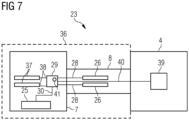
- Fig. 7 illustrates functional components of the pitch system 23.
- the hub 7 and the main shaft 8 as rotating part 36 of the wind turbine 1 are shown.
- the nacelle 4 as stationary part of the wind turbine 1 is shown (stationary with respect to a rotation of the rotor 2 and the main shaft 8).
- the pitch drive 25 of the pitch system 23 is, for example, arranged in the hub 7. Further, the distribution unit 29 (e.g., the manifold 29' in case of a hydraulic pitch drive 25') is shown in the hub 7. Furthermore, the at least one energy storage unit 26 is arranged in the cavity 17 ( Fig. 2 ) of the main shaft 8. Each of the at least one energy storage units 26 is connected by the energy line 28 to the distribution unit 29. Further, the pitch drive 25 is connected by the energy line 30 to the distribution unit 29.
- each of the at least one further energy storage unit 37 is connected by an energy line 38 to the distribution unit 29.
- the pitch system 23 may, for example, further include an energy source 39 arranged in the nacelle 4 for charging the at least one energy storage unit 26 in the cavity 17 of the main shaft 8.
- the energy source 39 in the nacelle 4 may in addition be configured for charging the at least one further energy storage unit 37 in the hub 7.
- the distribution unit 29 may be connected by a connecting energy line 40 with the energy source 39 in the nacelle 4.
- the pitch system 23 comprises one or more sensors 41 arranged at the distribution unit 29 for monitoring a status of the connecting energy line 40 and/or of the energy source 39 in the nacelle 4.
- the pitch drive 25 can be supplied with energy solely from the at least one energy storage unit 26 arranged in the cavity 17 of the main shaft 8 and/or from at the least one further energy storage unit 37 arranged in the rotor hub 7.
- the pitch system 23 can be used for aerodynamically braking the rotor blades 6 in case of an emergency, even when a supply of energy from the energy source 39 in the nacelle 4 is not possible.
Landscapes
- Engineering & Computer Science (AREA)
- Life Sciences & Earth Sciences (AREA)
- Sustainable Development (AREA)
- Sustainable Energy (AREA)
- Chemical & Material Sciences (AREA)
- Combustion & Propulsion (AREA)
- Mechanical Engineering (AREA)
- General Engineering & Computer Science (AREA)
- Wind Motors (AREA)
Priority Applications (1)
| Application Number | Priority Date | Filing Date | Title |
|---|---|---|---|
| EP23195595.6A EP4520962A1 (fr) | 2023-09-06 | 2023-09-06 | Éolienne |
Applications Claiming Priority (1)
| Application Number | Priority Date | Filing Date | Title |
|---|---|---|---|
| EP23195595.6A EP4520962A1 (fr) | 2023-09-06 | 2023-09-06 | Éolienne |
Publications (1)
| Publication Number | Publication Date |
|---|---|
| EP4520962A1 true EP4520962A1 (fr) | 2025-03-12 |
Family
ID=87933831
Family Applications (1)
| Application Number | Title | Priority Date | Filing Date |
|---|---|---|---|
| EP23195595.6A Withdrawn EP4520962A1 (fr) | 2023-09-06 | 2023-09-06 | Éolienne |
Country Status (1)
| Country | Link |
|---|---|
| EP (1) | EP4520962A1 (fr) |
Citations (2)
| Publication number | Priority date | Publication date | Assignee | Title |
|---|---|---|---|---|
| EP1138966A1 (fr) * | 2000-03-28 | 2001-10-04 | Tacke Windenergie GmbH | Installation éolienne |
| CN112283044A (zh) * | 2020-11-25 | 2021-01-29 | 北京三力新能科技有限公司 | 一种风力发电机组的蓄能器固定装置 |
-
2023
- 2023-09-06 EP EP23195595.6A patent/EP4520962A1/fr not_active Withdrawn
Patent Citations (2)
| Publication number | Priority date | Publication date | Assignee | Title |
|---|---|---|---|---|
| EP1138966A1 (fr) * | 2000-03-28 | 2001-10-04 | Tacke Windenergie GmbH | Installation éolienne |
| CN112283044A (zh) * | 2020-11-25 | 2021-01-29 | 北京三力新能科技有限公司 | 一种风力发电机组的蓄能器固定装置 |
Similar Documents
| Publication | Publication Date | Title |
|---|---|---|
| US8030790B2 (en) | Hybrid water pressure energy accumulating wind turbine and method | |
| EP2217807B1 (fr) | Eolienne avec pivot hydraulique | |
| US20230332574A1 (en) | Vertical wind turbine comprising rotor blade-supporting pitch motor, as well as kit for same, and method for operating same | |
| US20060275121A1 (en) | Wind turbine with friction drive power take off on outer rim | |
| US20070132247A1 (en) | Electric power generation system | |
| CN102606397B (zh) | 风轮机及驱动一个或更多个液压变桨致动器的方法 | |
| US20080253892A1 (en) | Tension Wheel Hub in a Rotor System for Wind and Water Turbines | |
| KR100832053B1 (ko) | 유체 토크 컨버터를 이용한 풍력 발전 시스템 | |
| EP4198299B1 (fr) | Procédés de fonctionnement d'éoliennes et de chargement de sources d'alimentation auxiliaire | |
| CN110892153A (zh) | 具有同轴的变桨马达的立式风力发电设备以及其安装套件和其运行方法 | |
| EP3696403B1 (fr) | Système et procédé pour protéger les éoliennes contre le battement pendant les vitesses de vent élevées | |
| WO2012169991A1 (fr) | Éolienne à accumulation d'énergie de pression d'eau hybride et procédé | |
| CN110892152A (zh) | 具有经调节的叶尖速比特性的立式风力发电设备以及其安装套件和其运行方法 | |
| WO2020047104A1 (fr) | Ensemble contrepoids destiné à être utilisé pendant le montage pale après pale du rotor d'une éolienne | |
| US10823138B2 (en) | Counterweight assembly for use during single blade installation of a wind turbine | |
| EP4520962A1 (fr) | Éolienne | |
| WO2021170317A1 (fr) | Éolienne pouvant fonctionner dans un mode de fonctionnement inversé et procédé correspondant de fonctionnement d'une éolienne | |
| US12429027B2 (en) | Methods for operating wind turbines and feeding auxiliary systems | |
| CN220667720U (zh) | 一种共轴式反向双叶轮传动链结构及风力发电机组 | |
| CN216617743U (zh) | 一种多机头风力发电机组用偏航回转支承 | |
| JP6887933B2 (ja) | 風力発電装置 | |
| CN119755032A (zh) | 具有外部功率供应部的风力涡轮系统以及方法 | |
| KR20090096254A (ko) | 가압분출, 집풍 및 차풍을 이용한 복합적 고효율풍력발전기 | |
| KR20070096517A (ko) | 차풍, 집풍 및 가압분출 복합고효율 풍력발전기 |
Legal Events
| Date | Code | Title | Description |
|---|---|---|---|
| PUAI | Public reference made under article 153(3) epc to a published international application that has entered the european phase |
Free format text: ORIGINAL CODE: 0009012 |
|
| STAA | Information on the status of an ep patent application or granted ep patent |
Free format text: STATUS: THE APPLICATION HAS BEEN PUBLISHED |
|
| AK | Designated contracting states |
Kind code of ref document: A1 Designated state(s): AL AT BE BG CH CY CZ DE DK EE ES FI FR GB GR HR HU IE IS IT LI LT LU LV MC ME MK MT NL NO PL PT RO RS SE SI SK SM TR |
|
| STAA | Information on the status of an ep patent application or granted ep patent |
Free format text: STATUS: THE APPLICATION IS DEEMED TO BE WITHDRAWN |
|
| 18D | Application deemed to be withdrawn |
Effective date: 20250913 |