EP4520977A1 - Carter de pompe centrifuge - Google Patents
Carter de pompe centrifuge Download PDFInfo
- Publication number
- EP4520977A1 EP4520977A1 EP23195755.6A EP23195755A EP4520977A1 EP 4520977 A1 EP4520977 A1 EP 4520977A1 EP 23195755 A EP23195755 A EP 23195755A EP 4520977 A1 EP4520977 A1 EP 4520977A1
- Authority
- EP
- European Patent Office
- Prior art keywords
- centrifugal pump
- pump casing
- metal
- inlet
- funnel
- Prior art date
- Legal status (The legal status is an assumption and is not a legal conclusion. Google has not performed a legal analysis and makes no representation as to the accuracy of the status listed.)
- Pending
Links
Images
Classifications
-
- F—MECHANICAL ENGINEERING; LIGHTING; HEATING; WEAPONS; BLASTING
- F04—POSITIVE - DISPLACEMENT MACHINES FOR LIQUIDS; PUMPS FOR LIQUIDS OR ELASTIC FLUIDS
- F04D—NON-POSITIVE-DISPLACEMENT PUMPS
- F04D29/00—Details, component parts, or accessories
- F04D29/40—Casings; Connections of working fluid
- F04D29/42—Casings; Connections of working fluid for radial or helico-centrifugal pumps
- F04D29/426—Casings; Connections of working fluid for radial or helico-centrifugal pumps especially adapted for liquid pumps
- F04D29/4286—Casings; Connections of working fluid for radial or helico-centrifugal pumps especially adapted for liquid pumps inside lining, e.g. rubber
-
- F—MECHANICAL ENGINEERING; LIGHTING; HEATING; WEAPONS; BLASTING
- F04—POSITIVE - DISPLACEMENT MACHINES FOR LIQUIDS; PUMPS FOR LIQUIDS OR ELASTIC FLUIDS
- F04D—NON-POSITIVE-DISPLACEMENT PUMPS
- F04D29/00—Details, component parts, or accessories
- F04D29/02—Selection of particular materials
- F04D29/026—Selection of particular materials especially adapted for liquid pumps
-
- F—MECHANICAL ENGINEERING; LIGHTING; HEATING; WEAPONS; BLASTING
- F04—POSITIVE - DISPLACEMENT MACHINES FOR LIQUIDS; PUMPS FOR LIQUIDS OR ELASTIC FLUIDS
- F04D—NON-POSITIVE-DISPLACEMENT PUMPS
- F04D29/00—Details, component parts, or accessories
- F04D29/40—Casings; Connections of working fluid
- F04D29/42—Casings; Connections of working fluid for radial or helico-centrifugal pumps
- F04D29/426—Casings; Connections of working fluid for radial or helico-centrifugal pumps especially adapted for liquid pumps
-
- F—MECHANICAL ENGINEERING; LIGHTING; HEATING; WEAPONS; BLASTING
- F05—INDEXING SCHEMES RELATING TO ENGINES OR PUMPS IN VARIOUS SUBCLASSES OF CLASSES F01-F04
- F05D—INDEXING SCHEME FOR ASPECTS RELATING TO NON-POSITIVE-DISPLACEMENT MACHINES OR ENGINES, GAS-TURBINES OR JET-PROPULSION PLANTS
- F05D2300/00—Materials; Properties thereof
- F05D2300/10—Metals, alloys or intermetallic compounds
- F05D2300/12—Light metals
- F05D2300/121—Aluminium
-
- F—MECHANICAL ENGINEERING; LIGHTING; HEATING; WEAPONS; BLASTING
- F05—INDEXING SCHEMES RELATING TO ENGINES OR PUMPS IN VARIOUS SUBCLASSES OF CLASSES F01-F04
- F05D—INDEXING SCHEME FOR ASPECTS RELATING TO NON-POSITIVE-DISPLACEMENT MACHINES OR ENGINES, GAS-TURBINES OR JET-PROPULSION PLANTS
- F05D2300/00—Materials; Properties thereof
- F05D2300/10—Metals, alloys or intermetallic compounds
- F05D2300/17—Alloys
- F05D2300/171—Steel alloys
-
- F—MECHANICAL ENGINEERING; LIGHTING; HEATING; WEAPONS; BLASTING
- F05—INDEXING SCHEMES RELATING TO ENGINES OR PUMPS IN VARIOUS SUBCLASSES OF CLASSES F01-F04
- F05D—INDEXING SCHEME FOR ASPECTS RELATING TO NON-POSITIVE-DISPLACEMENT MACHINES OR ENGINES, GAS-TURBINES OR JET-PROPULSION PLANTS
- F05D2300/00—Materials; Properties thereof
- F05D2300/10—Metals, alloys or intermetallic compounds
- F05D2300/17—Alloys
- F05D2300/172—Copper alloys
-
- F—MECHANICAL ENGINEERING; LIGHTING; HEATING; WEAPONS; BLASTING
- F05—INDEXING SCHEMES RELATING TO ENGINES OR PUMPS IN VARIOUS SUBCLASSES OF CLASSES F01-F04
- F05D—INDEXING SCHEME FOR ASPECTS RELATING TO NON-POSITIVE-DISPLACEMENT MACHINES OR ENGINES, GAS-TURBINES OR JET-PROPULSION PLANTS
- F05D2300/00—Materials; Properties thereof
- F05D2300/40—Organic materials
- F05D2300/43—Synthetic polymers, e.g. plastics; Rubber
Definitions
- the invention relates to a centrifugal pump casing.
- the devices according to the present invention may generally be applied in the field of fluid pumping, such as for pumping water or other fluids, for example in thermal management applications.
- the invention may be applied in automotive thermal management, such as in the field of thermal management of vehicles, e.g. in the cooling and/or heating of cars and trucks.
- the invention may be applied in the field of thermally managing arbitrary electric and electronic applications.
- Other applications however, such as in for example in gardening tools, are also feasible.
- centrifugal pumps For managing and/or controlling fluid flow, e.g. in thermal management systems or manifolds, centrifugal pumps are used.
- centrifugal pumps comprise a centrifugal pump casing that receives the fluid being pumped by an impeller and usually comprises a curved funnel, increasing in area as it approaches a discharge port.
- the fluid travels along the centrifugal pump casing it is joined by more and more fluid exiting the impeller.
- the increasing area, e.g. cross sectional area, of the pump casing ideally the velocity of the fluid is maintained.
- the centrifugal pump casing directs this flow through to the discharge port.
- the impeller and the centrifugal pump casing have to be aligned within tight tolerances. Due to the tight tolerances, at least a flange part of the centrifugal pump casing typically is made of a metal material, wherein sealing rings, typically O-rings, are used for sealing purposes, keeping the fluid within the centrifugal pump casing and generally preventing the fluid from reaching the motor driving the rotation of the impeller.
- sealing rings typically O-rings
- DE 102014213154 A1 describes a flange connection between a metal component and a plastic component, wherein the plastic component has a component opening enclosed by an opening rim of plastic, wherein the metal component has a flange of metal, the flange having a plastic frame injection-molded thereon, which is welded to the opening edge in such a way that a weld zone closed around the component opening is formed between the frame and the opening edge, wherein a permanent tightness of the flange connection is aimed for from at least one seal running closed along the flange, which is in contact with the metal of the flange.
- DE 102016125250 B4 describes a method for the continuous manufacture of seals, in which a plurality of reinforcing inserts is produced by cutting individual sections from a flat material. Further, a compound is introduced into an extruder and the reinforcing inserts are fed to the extruder in a timed manner in order to be overmolded with the compound in the extruder. Furthermore, the reinforcing inserts are being fed and overmolded longitudinally one after the other and at a distance from one another as a result of the timing and a continuous strand of overmolded compound is ejected from the extruder, which strand includes and completely encloses the mutually spaced reinforcing inserts.
- a plurality of seals are produced by continuously severing the strand between adjacent reinforcing inserts in each case, wherein the severing is performed at such portions of the strand having the spacings between adjacent reinforcing inserts so that the reinforcing inserts remain completely enclosed by the compound, wherein the portions of the continuous strand having the spacings between the reinforcing inserts are marked, or alternatively the portions having the reinforcing inserts are marked.
- a light centrifugal pump casing shall be proposed, which allows for a simple assembly and manufacturing of a centrifugal pump.
- the terms “have”, “comprise” or “include” or any arbitrary grammatical variations thereof are used in a non-exclusive way. Thus, these terms may both refer to a situation in which, besides the feature introduced by these terms, no further features are present in the entity described in this context and to a situation in which one or more further features are present.
- the expressions “A has B”, “A comprises B” and “A includes B” may both refer to a situation in which, besides B, no other element is present in A (i.e. a situation in which A solely and exclusively consists of B) and to a situation in which, besides B, one or more further elements are present in entity A, such as element C, elements C and D or even further elements.
- the terms "at least one”, “one or more” or similar expressions indicating that a feature or element may be present once or more than once typically will be used only once when introducing the respective feature or element.
- the expressions “at least one” or “one or more” will not be repeated, non-withstanding the fact that the respective feature or element may be present once or more than once.
- a centrifugal pump casing comprises at least one inlet through which a fluid is admittable into the centrifugal pump casing.
- the centrifugal pump casing further comprises at least one flange via which the centrifugal pump casing is mountable relative to an impeller insertable into the centrifugal pump casing.
- the centrifugal pump casing comprises at least one funnel in which the impeller is rotatable for pumping the fluid, wherein the inlet, the funnel and the flange are formed as one piece from at least one plastic material.
- the centrifugal pump casing comprises at least two metal inlays at least partially overmolded by the plastic material of the inlet, the funnel and the flange.
- the centrifugal pump casing may be configured to be used and arranged in a vehicle, such as in a car and/or truck.
- the centrifugal pump casing may be part of a thermal management manifold of the vehicle, such as of the car and/or truck.
- centrifugal pump casing is a broad term and is to be given its ordinary and customary meaning to a person of ordinary skill in the art and is not to be limited to a special or customized meaning.
- the term specifically may refer, without limitation, to a housing of a centrifugal pump configured for receiving an arbitrary fluid and an impeller for pumping the fluid.
- the term "fluid" may specifically refer to an arbitrary liquid medium, such as for example comprising water.
- the fluid may be a cooling agent, configured for removing heat and/or for conducting heat to a heat sink.
- the fluid may specifically comprise at least one liquid selected from the group consisting of: water, oil, dielectric oil, refrigerant fluid, heat transfer fluid, insulating oil and glycol.
- outlet is a broad term and is to be given its ordinary and customary meaning to a person of ordinary skill in the art and is not to be limited to a special or customized meaning.
- the term specifically may refer, without limitation, to an entrance into the centrifugal pump casing through which the fluid may enter into the centrifugal pump casing.
- flange as used herein is a broad term and is to be given its ordinary and customary meaning to a person of ordinary skill in the art and is not to be limited to a special or customized meaning.
- the term specifically may refer, without limitation, to a part of the centrifugal pump casing via for mounting the centrifugal pump casing relative to the impeller, i.e. to an axis of rotation of the impeller.
- the flange may be a ring shaped disc via which the centrifugal pump casing may be fixed and/or mounted to an arbitrary fixing means, such as for example within a vehicle or other object in which the centrifugal pump is to be applied.
- frunnel as used herein is a broad term and is to be given its ordinary and customary meaning to a person of ordinary skill in the art and is not to be limited to a special or customized meaning.
- the term specifically may refer, without limitation, to a volute in which the impeller is rotatable, such as to, in conjunction with the funnel, pumping the fluid, thereby charging the fluid with kinetic energy.
- metal inlay as used herein is a broad term and is to be given its ordinary and customary meaning to a person of ordinary skill in the art and is not to be limited to a special or customized meaning.
- the term specifically may refer, without limitation, to an arbitrary metal part having the shape of at least a partial circle and configured for being at least partially overmolded by another material, specifically by a plastic material.
- the metal inlay may be configured for providing at least one stabilizing bearing area of the impeller within the centrifugal pump casing.
- the funnel may specifically comprise at least one outlet through which the fluid is dischargeable from the centrifugal pump casing.
- outlet is a broad term and is to be given its ordinary and customary meaning to a person of ordinary skill in the art and is not to be limited to a special or customized meaning.
- the term specifically may refer, without limitation, to an exit from the centrifugal pump casing through which the fluid may leave the centrifugal pump casing.
- At least one of the metal inlays may specifically be at least partially ring shaped, such as at least one partial ring.
- the metal inlays may for example be partial rings, such as half rings, e.g. two half rings to complete a circle.
- the metal inlays may be or may comprise circular metal inlays, such as ring shaped circular metal inlays.
- at least one of the metal inlays may be or may comprise multiple partial rings that may be put together in such a way that they form a whole circle, i.e. with interruptions.
- the metal inlays may have a rotationally symmetrical shape with respect to at least one axis.
- the metal inlays may have a rotationally symmetrically shape with respect to the impeller's axis of rotation.
- the metal inlays may be arranged within the plastic material of the inlet, the funnel and the flange.
- At least one of the metal inlays may have an L-shaped cross section.
- L-shaped cross section as used herein is a broad term and is to be given its ordinary and customary meaning to a person of ordinary skill in the art and is not to be limited to a special or customized meaning.
- the term specifically may refer, without limitation, to a cross section shaped like an "L” having an angle between the L's two extremities, such as between its horizontal and vertical part, in the range of from 45° to 135°.
- the L-shaped cross section may comprise an angle in the range of from 70° to 110° between its extremities.
- the horizontal part of the L-shaped cross section may specifically extend radially outward, e.g. away from the axis, specifically away from the impeller's axis of rotation.
- the vertical part of the L-shaped cross section may be arranged parallel to the axis, specifically parallel to the impeller's axis of rotation.
- At least a part of one side of a bend of the L-shaped cross section of the metal inlays may be exposed and not covered by the plastic material of the inlet, the funnel and the flange.
- an outer side of the bend of the L-shaped cross section of the metal inlays may be exposed and not covered by the plastic material of the inlet, the funnel and the flange.
- At least two of the metal inlays may have different diameters.
- the diameter, i.e. the double radius, of at least one partially ring shaped metal inlay, such as of at least one metal inlay shaped as a partial ring may differ from the diameter of at least one other one of the at last partially ring shaped metal inlay.
- the centrifugal pump casing may comprise exactly two metal inlays.
- the diameter of the first of the fully or partially ring shaped metal inlay may differ from the diameter of the second of the fully or partially ring shaped metal inlay.
- the metal inlay arranged closer to the inlet may have a smaller diameter than the metal inlay arranged farther away from the inlet.
- the funnel may be arranged between the inlet and the flange.
- the funnel e.g. the volute, of the centrifugal pump casing may be arranged such that it is geometrically positioned between the inlet and the flange.
- the plastic material may specifically comprise at least one material selected from the group consisting of glycol resistant plastic, oil resistant plastic, polypropylene (PP), polyamide (PA), polyamide 6 (PA6), polyketone (PK), polyamide 66 (PA66), polyoxymethylene (POM) and polyamide 9T (PA9T).
- PP polypropylene
- PA polyamide
- PA6 polyamide 6
- PK polyketone
- PA66 polyamide 66
- POM polyoxymethylene
- PA9T polyamide 9T
- the plastic material may further comprise one or more of glass fibers (GF) and carbon fibers (CF).
- the filler of the plastic material may comprise GF in the range of from 5 %-weight to 60 %-weight of the plastic material.
- the filler of the plastic material may comprise GF in the range of from 8 %-weight to 50 %-weight of the plastic material.
- the filler of the plastic material may comprise GF in the range of from 10 %-weight to 30 %-weight of the plastic material.
- the filler of the plastic material may comprise CF in the range of from 5 %-weight to 60 %-weight of the plastic material.
- the filler of the plastic material may comprise CF in the range of from 8 %-weight to 50 %-weight of the plastic material. More specifically, the filler of the plastic material may comprise CF in the range of from 10 %-weight to 25 %-weight of the plastic material.
- At least one of the metal inlays may for example comprise at least one metal material selected from the group consisting of copper, steel, specifically stainless steel, and aluminum.
- a method of manufacturing a centrifugal pump casing as described herein comprises the following steps.
- the steps may be performed in the given order. Still, a different order is possible.
- the method may comprise additional steps, which are not mentioned. It is further possible to perform one or more or all of the method steps repeatedly. Further, two of the method steps may be performed simultaneously or in a timely overlapping fashion.
- the method comprises the following steps:
- the method is configured for manufacturing the centrifugal pump casing as described herein.
- the proposed devices and methods provide a large number of advantages over known devices and methods of similar kind.
- the devices and methods according to the present application may reduce the total weight of the centrifugal pump casing, thereby allowing for reducing emissions both during manufacturing and assembly as well as, in case of installation in a vehicle, during usage of the centrifugal pump casing.
- the proposed devices and methods may reduce assembly and manufacturing complexity.
- the proposed centrifugal pump casing may have a reduced number of components compared to known devices. This may specifically help reduce manufacturing costs and complexity of the assembly. For example, by a reduced number of interfaces and/or boundary surfaces, i.e. when assembling the components to form the centrifugal pump, compared to known devices and methods.
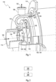
- centrifugal pump casing 110 comprises at least one inlet 112 through which a fluid is admittable into the centrifugal pump casing 110.
- the centrifugal pump casing 110 further comprises at least one flange 114 via which the centrifugal pump casing 110 is mountable relative to an impeller 116 insertable into the centrifugal pump casing 110.
- the centrifugal pump casing 110 comprises at least one funnel 118 in which the impeller 116 is rotatable for pumping the fluid, wherein the inlet 112, the funnel 118 and the flange 114 are formed as one piece from at least one plastic material.
- the centrifugal pump casing 110 comprises at least two metal inlays 120 at least partially overmolded by the plastic material of the inlet 112, the funnel 118 and the flange 114.
- the metal inlays 120 may be circular, ring shaped metal inlays. Alternatively however, each metal inlay 120 may be or may comprise one or more partial rings, for example two half rings or four quarter rings.
- the metal inlays 120 may have different diameters. Thus, for example a first metal inlay 122, arranged closer to the inlet 112 may have a smaller diameter than a second metal inlay 124 arranged farther away from the inlet 112.
- the metal inlays 120 may specifically be configured for providing at least one stabilizing bearing area and/or bearing surface 125 for the impeller 116 within the centrifugal pump casing 110.
- the funnel 118 may be arranged between the inlet 112 and the flange 114.
- the funnel 118 of the centrifugal pump casing110 may further comprise at least one outlet 126 through which the fluid may be dischargeable from the centrifugal pump casing 110.
- a centrifugal pump including the centrifugal pump casing 110 may be described as follows: In the figure, the fluid entering the centrifugal pump casing 110 may be illustrated by a first arrow 128. The fluid that has entered the centrifugal pump casing 110, is then pumped by the impeller 116, in conjunction with the funnel 118, thereby changing the fluid's flow direction, as illustrated by a second arrow 130. Further, the fluid, when pumped by the impeller 116, travels along the funnel 118 and is joined by more and more fluid exiting the impeller 116, before exiting the funnel 118 through the funnel's outlet 126, as illustrated by the third arrow 132.
- the impeller 116 may specifically be alignable within the centrifugal pump casing 110, specifically supported by the bearing surface 125, and may rotate around the axis 134.
- the metal inlays 120 may for example have a rotationally symmetrical shape with respect to the axis 134 and may have an L-shaped cross section, wherein the horizontal part 136 of the L-shaped cross section may extends radially outward, away from the axis 134, and wherein the vertical part 138 of the L-shaped cross section may be arranged parallel to the axis 134.
- At least a part of one side of a bend 140 of the L-shaped cross section, specifically an outer side of the bend 140 of the L-shaped cross section, of the metal inlays 120 may be exposed and not covered by the plastic material of the inlet 112, the funnel 118 and the flange 114.
- Figure 2 illustrates a flow chart of a method of manufacturing a centrifugal pump casing 110. The method comprises the following steps:
Landscapes
- Engineering & Computer Science (AREA)
- Mechanical Engineering (AREA)
- General Engineering & Computer Science (AREA)
- Structures Of Non-Positive Displacement Pumps (AREA)
Priority Applications (1)
| Application Number | Priority Date | Filing Date | Title |
|---|---|---|---|
| EP23195755.6A EP4520977A1 (fr) | 2023-09-06 | 2023-09-06 | Carter de pompe centrifuge |
Applications Claiming Priority (1)
| Application Number | Priority Date | Filing Date | Title |
|---|---|---|---|
| EP23195755.6A EP4520977A1 (fr) | 2023-09-06 | 2023-09-06 | Carter de pompe centrifuge |
Publications (1)
| Publication Number | Publication Date |
|---|---|
| EP4520977A1 true EP4520977A1 (fr) | 2025-03-12 |
Family
ID=87933745
Family Applications (1)
| Application Number | Title | Priority Date | Filing Date |
|---|---|---|---|
| EP23195755.6A Pending EP4520977A1 (fr) | 2023-09-06 | 2023-09-06 | Carter de pompe centrifuge |
Country Status (1)
| Country | Link |
|---|---|
| EP (1) | EP4520977A1 (fr) |
Citations (5)
| Publication number | Priority date | Publication date | Assignee | Title |
|---|---|---|---|---|
| US5823753A (en) * | 1994-10-29 | 1998-10-20 | Pierburg Gmbh | Metal reinforced pump cover of an electrically driven air pump |
| DE102014213154A1 (de) | 2014-07-07 | 2016-01-07 | Mahle International Gmbh | Flanschverbindung und Herstellungsverfahren |
| KR20200108739A (ko) * | 2019-03-11 | 2020-09-21 | (주)트라코월드 | 보강된 마우스링부를 갖는 케미컬 펌프용 프런트 케이싱 및 그의 제작 방법 |
| CN111963482A (zh) * | 2020-09-18 | 2020-11-20 | 台州市禺工泵业科技有限公司 | 一种塑料泵进出水口的增强防渗漏结构 |
| DE102016125250B4 (de) | 2016-12-21 | 2021-10-07 | Webasto SE | Verfahren zur Herstellung von Dichtungen |
-
2023
- 2023-09-06 EP EP23195755.6A patent/EP4520977A1/fr active Pending
Patent Citations (5)
| Publication number | Priority date | Publication date | Assignee | Title |
|---|---|---|---|---|
| US5823753A (en) * | 1994-10-29 | 1998-10-20 | Pierburg Gmbh | Metal reinforced pump cover of an electrically driven air pump |
| DE102014213154A1 (de) | 2014-07-07 | 2016-01-07 | Mahle International Gmbh | Flanschverbindung und Herstellungsverfahren |
| DE102016125250B4 (de) | 2016-12-21 | 2021-10-07 | Webasto SE | Verfahren zur Herstellung von Dichtungen |
| KR20200108739A (ko) * | 2019-03-11 | 2020-09-21 | (주)트라코월드 | 보강된 마우스링부를 갖는 케미컬 펌프용 프런트 케이싱 및 그의 제작 방법 |
| CN111963482A (zh) * | 2020-09-18 | 2020-11-20 | 台州市禺工泵业科技有限公司 | 一种塑料泵进出水口的增强防渗漏结构 |
Similar Documents
| Publication | Publication Date | Title |
|---|---|---|
| EP3001037B1 (fr) | Pompe électrique à fluide avec rotor amélioré et procédé de construction de celle-ci | |
| CN100451348C (zh) | 离心式鼓风机 | |
| KR101761677B1 (ko) | 모터하우징용 냉각장치 | |
| JP5382316B2 (ja) | 電動アシスト過給機の冷却構造 | |
| CN108292878B (zh) | 用于电机的冷却壳体及其制造方法 | |
| EP1612023B1 (fr) | Ventilateur en plastique moulé avec ligne de soudure renforcée dans l'anneau stabilisateur. | |
| US7074019B2 (en) | Rotor protector for wet-type rotor pump | |
| CN103609003B (zh) | 冷却壳和用于冷却壳的偏转单元 | |
| CN113482973A (zh) | 具有在轴向热交换器装置中的冷却空气通道和液体冷却剂通道的压缩机 | |
| US6158979A (en) | Device for fixing a motor-fan unit on a motor vehicle element, in particular a heat exchanger | |
| CN112311146B (zh) | 马达的冷却部件 | |
| WO2000047898A1 (fr) | Pompe a fluide | |
| EP4520977A1 (fr) | Carter de pompe centrifuge | |
| US11336138B2 (en) | Hybrid rotor module cooling | |
| CN111237048A (zh) | 涡轮增压器 | |
| US20180073520A1 (en) | Charging device | |
| CN112997008A (zh) | 叶轮、具有该叶轮的泵、以及该叶轮的制造方法 | |
| RU2556475C2 (ru) | Система уплотнений для центробежных насосов | |
| US20030021708A1 (en) | Aggregate for conveying fuel | |
| EP1178207A1 (fr) | Pompe electrique a carburant | |
| US9500086B2 (en) | Impeller and electric-motor driven water pump having the same | |
| EP4712319A2 (fr) | Moteur | |
| US11802528B2 (en) | Fuel delivery assembly and fuel delivery unit | |
| CN211744173U (zh) | 电机冷却结构、电机及汽车 | |
| US20240418179A1 (en) | Fan wheel and a method of manufacturing thereof |
Legal Events
| Date | Code | Title | Description |
|---|---|---|---|
| PUAI | Public reference made under article 153(3) epc to a published international application that has entered the european phase |
Free format text: ORIGINAL CODE: 0009012 |
|
| STAA | Information on the status of an ep patent application or granted ep patent |
Free format text: STATUS: THE APPLICATION HAS BEEN PUBLISHED |
|
| AK | Designated contracting states |
Kind code of ref document: A1 Designated state(s): AL AT BE BG CH CY CZ DE DK EE ES FI FR GB GR HR HU IE IS IT LI LT LU LV MC ME MK MT NL NO PL PT RO RS SE SI SK SM TR |
|
| STAA | Information on the status of an ep patent application or granted ep patent |
Free format text: STATUS: REQUEST FOR EXAMINATION WAS MADE |
|
| 17P | Request for examination filed |
Effective date: 20250408 |
|
| RIN1 | Information on inventor provided before grant (corrected) |
Inventor name: BARBOLINI, MARCO Inventor name: KERSCHBAUMER, DIETER Inventor name: HOLZNER, GUENTHER |