EP4520983A1 - Bouton-pression amélioré - Google Patents
Bouton-pression amélioré Download PDFInfo
- Publication number
- EP4520983A1 EP4520983A1 EP24198440.0A EP24198440A EP4520983A1 EP 4520983 A1 EP4520983 A1 EP 4520983A1 EP 24198440 A EP24198440 A EP 24198440A EP 4520983 A1 EP4520983 A1 EP 4520983A1
- Authority
- EP
- European Patent Office
- Prior art keywords
- retention member
- resilient retention
- snap fastener
- cavity
- diameter
- Prior art date
- Legal status (The legal status is an assumption and is not a legal conclusion. Google has not performed a legal analysis and makes no representation as to the accuracy of the status listed.)
- Granted
Links
Images



Classifications
-
- F—MECHANICAL ENGINEERING; LIGHTING; HEATING; WEAPONS; BLASTING
- F16—ENGINEERING ELEMENTS AND UNITS; GENERAL MEASURES FOR PRODUCING AND MAINTAINING EFFECTIVE FUNCTIONING OF MACHINES OR INSTALLATIONS; THERMAL INSULATION IN GENERAL
- F16B—DEVICES FOR FASTENING OR SECURING CONSTRUCTIONAL ELEMENTS OR MACHINE PARTS TOGETHER, e.g. NAILS, BOLTS, CIRCLIPS, CLAMPS, CLIPS OR WEDGES; JOINTS OR JOINTING
- F16B21/00—Means for preventing relative axial movement of a pin, spigot, shaft or the like and a member surrounding it; Stud-and-socket releasable fastenings
- F16B21/06—Releasable fastening devices with snap-action
- F16B21/07—Releasable fastening devices with snap-action in which the socket has a resilient part
- F16B21/078—Releasable fastening devices with snap-action in which the socket has a resilient part the socket having a further molded-in or embedded component, e.g. a ring with snap-in teeth molded into it
-
- A—HUMAN NECESSITIES
- A44—HABERDASHERY; JEWELLERY
- A44B—BUTTONS, PINS, BUCKLES, SLIDE FASTENERS, OR THE LIKE
- A44B17/00—Press-button or snap fasteners
- A44B17/0011—Press-button fasteners in which the elastic retaining action is obtained by a spring working in the plane of the fastener
-
- A—HUMAN NECESSITIES
- A44—HABERDASHERY; JEWELLERY
- A44B—BUTTONS, PINS, BUCKLES, SLIDE FASTENERS, OR THE LIKE
- A44B17/00—Press-button or snap fasteners
- A44B17/0047—Press-button fasteners consisting of three parts
-
- A—HUMAN NECESSITIES
- A44—HABERDASHERY; JEWELLERY
- A44B—BUTTONS, PINS, BUCKLES, SLIDE FASTENERS, OR THE LIKE
- A44B17/00—Press-button or snap fasteners
- A44B17/0064—Details
- A44B17/0076—Socket member
-
- F—MECHANICAL ENGINEERING; LIGHTING; HEATING; WEAPONS; BLASTING
- F16—ENGINEERING ELEMENTS AND UNITS; GENERAL MEASURES FOR PRODUCING AND MAINTAINING EFFECTIVE FUNCTIONING OF MACHINES OR INSTALLATIONS; THERMAL INSULATION IN GENERAL
- F16B—DEVICES FOR FASTENING OR SECURING CONSTRUCTIONAL ELEMENTS OR MACHINE PARTS TOGETHER, e.g. NAILS, BOLTS, CIRCLIPS, CLAMPS, CLIPS OR WEDGES; JOINTS OR JOINTING
- F16B21/00—Means for preventing relative axial movement of a pin, spigot, shaft or the like and a member surrounding it; Stud-and-socket releasable fastenings
- F16B21/06—Releasable fastening devices with snap-action
- F16B21/07—Releasable fastening devices with snap-action in which the socket has a resilient part
- F16B21/073—Releasable fastening devices with snap-action in which the socket has a resilient part the socket having a resilient part on its inside
Definitions
- the present invention relates to a snap fastener.
- the invention has been developed with particular regard to an improved snap fastener for use in clothing and/or in leather goods.
- Snap fasteners are generally known and comprise a female element and a male element which can be connected to each other in a disconnectable manner by means of a resiliently deformable engagement member, typically a ring, which is mounted in the female element, in a receiving seat. At least a portion of the male element can be selectively inserted into the receiving seat in a connection direction in order to move from an unbuttoned configuration, in which the male element and the female element are separated and disconnected, to a buttoned configuration, in which the two male and female elements are connected to each other.
- a fastener of this type is known from WO 1997/15207 .
- An object of the invention is to solve the problems of the prior art.
- an object is to provide an automatic fastener which is easier to fasten.
- Another object is to provide a fastener which is more resistant to accidental unbuttoning.
- Another object is to provide a fastener which is easier to button and at the same time more resistant to accidental unbuttoning.
- Another object is to provide an automatic fastener which is compact and does not take up much space.
- Another object is to provide an automatic fastener which is aesthetically pleasing, well refined in the portions which are visible even when it is unbuttoned.
- Another object is to provide a fastener which does not run the risk of becoming caught in clothing or objects.
- an object is to provide an automatic fastener which requires only minimal modifications to the production processes with respect to conventional snap fasteners.
- Another object is to provide a fastener which is economical, simple, reliable during use and secure.
- a snap fastener comprising a male element and a female element.
- the male element and the female element may be able to be connected to each other in a connection direction.
- the female element may comprise a cavity, in which a resilient retention member can be received.
- the cavity can be tapered, for example, in the form of a truncated cone.
- the resilient retention member may be suitable for gripping and retaining a connection portion of the male element.
- the resilient retention member may be movable inside the cavity. In this manner, when the fastener is buttoned, it may be located in a zone of the cavity having a first diameter or, during a fastening step, in another zone of the cavity having a second diameter, which is greater than the first diameter.
- the resilient retention member When the resilient retention member is located in a zone of the cavity having a greater diameter than the diameter at rest of the same resilient retention member, it is free to become wider.
- the possibility of the resilient retention member becoming wider during the fastening makes the automatic fastener extremely easy to button as a result of the reduced resistance provided by the resilient retention member.
- the fastener when the fastener is buttoned, there not being this possibility of expansion of the resilient retention member, the fastener can be unbuttoned only by compression of the resilient retention member and therefore requires greater force in order to be unbuttoned than buttoned.
- the resilient retention member is normally at rest when the fastener is buttoned and becomes deformed only during the fastening and unfastening operations, it is subjected to minimal wear, which is substantially negligible.
- a snap fastener comprising a male element and a female element.
- the female element may comprise a cavity, in which a resilient retention member can be received.
- the resilient retention member is suitable for gripping and retaining a connection portion of the male element.
- the automatic fastener becomes buttoned by applying thereto a force, in a direction parallel with the axes of the components of the fastener, which is less than the force which is applied to unbutton it.
- a snap fastener which is characterized by a predefined unbuttoning force, which is defined as the force necessary to unbutton the fastener, and a predefined buttoning force, which is defined as the force necessary to button the fastener, wherein the unbuttoning force is greater than the buttoning force.
- a snap fastener comprising a male element and a female element.
- the female element may comprise a cavity, in which a resilient retention member which is suitable for gripping and retaining a connection portion of the male element can be received.
- the resilient retention member may have an internal radius which is defined as the radius of a hole through which the connection portion of the male element is inserted, and an external radius, which is defined as the radius of the resilient retention member overall, wherein, when the fastener is being buttoned, the internal radius and the external radius both increase. When the fastener is being unbuttoned, preferably the external radius of the resilient retention member does not increase.
- a snap fastener comprising a male element and a female element which is provided with a resilient retention member.
- the resilient retention member may comprise a plurality of portions which are arranged along a circumference and which are connected to each other by a plurality of resilient connection elements.
- the connection elements preferably have a resilience greater than the portions.
- the fastener described is particularly compact so as to be able also to be used at locations where a very small fastener is required for aesthetic and/or technical reasons. Furthermore, the fastener which is formed in this manner has no visible sheet metal edge, which could be inconvenient, possibly even sharp or in any case aesthetically unpleasant.
- fastener according to the invention may appear to be generally identical with regard to the visible components to a conventional automatic fastener.
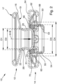
- a snap fastener 10 comprises a male element 12 and a female element 14.
- the two elements are fixed to two respective substrates, such as, for example, edges of fabric, hides, plastics material or the like, in order to be able to button them to each other.
- the fixing of the male and female elements to the respective substrates can be carried out according to known methods which are therefore not described in detail, for example, by means of riveting, nailing, stitching and other techniques which are generally known in the field.
- the male element 12 which is depicted is preferably made from brass or another metal. It comprises a base 16 which is, for example, generally disk-shaped, with a side 17 which is intended to be placed on the substrate during use.
- connection portion 20 projects from the base 16 of the male element 12, from a face 19 of the base 16 opposite the face 17 which is intended to be placed on the substrate during use.
- the connection portion 20 is intended to connect the male element 12 to the female element 14.
- the connection portion 20 comprises a substantially tubular member 22 which is generally narrower than the disk-shaped base 16 and which projects with respect to the disk-shaped base 16 from the face 19.
- the tubular member 22 has a head 24 with a diameter D1.
- the tubular member 22 is provided with a restriction 31 at the lateral wall 26 thereof.
- the tubular member 22 narrows to a diameter D2, which is less than the diameter D1 of the head 24.
- the female element 14 comprises a base 50 with a lower face 52, for example intended to be placed on the substrate during use and from which there extends a tubular member 55 which forms a cavity or receiving seat 54 for the connection portion 20 of the male element 12 and a receiving seat 60 for a resilient retention member.
- the receiving seat 60 has a tapered formation, that is to say, has a variable diameter between a diameter D3 in a zone facing towards the male element and a diameter D4 in the opposite direction.
- the lateral wall 70 which defines the receiving seat 60 has a frustoconical shape, but a different tapered formation is not excluded, for example, convex, with D3 being less than D4.
- the base 50 is preferably provided with a central hole 53 in order to fix the element to a substate, for example, for the passage of a fixing member, which is not illustrated, such as a rivet or the like.
- a resilient retention member 62 is received in the receiving seat 60 of the female element 14.
- the receiving seat 60 is closed by an annular retention edge 64 which prevents the resilient retention member 62 from leaving the receiving seat 60.
- the annular retention edge 64 is preferably constructed by means of a shaped metal sheet.
- the resilient retention member 62 comprises a plurality of portions 66 which are connected to each other by a plurality of resilient connection elements 68.
- the connection elements 68 extend transversely with respect to the plane in which the portions 66 are located, and are preferably U-shaped. As result of the material or preferably as a result of the formation and dimensions thereof, the connection elements are more flexible with respect to the portions 66.
- the portions 66 are arranged along a circumference and together define a hole 69, with an internal diameter D5 at rest, through which the connection portion 20 of the male element is inserted.
- the portions 66 together define an external radius D6, that is to say, the radius of the resilient retention member overall.
- connection elements 68 which are more flexible than the portions 66, allow the portions 66 to move away from each other, thereby increasing the internal diameter and the external diameter of the resilient retention member 62.
- the external diameter D6 is approximately identical to the minimum diameter D3 of the seat 60 for the resilient retention member 62 although it is possible to provide some play.
- the male element 12 and the female element 14 of the snap fastener 10 are fixed to two substrates, respectively, which it is desirable to fasten.
- the male element 12 is positioned with a longitudinal axis A thereof substantially coincident with the axis B of the female element 14.
- the head 24 of the male element 12 is placed on the opening of the receiving seat 54 of the female element 14.
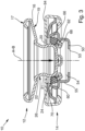
- the two elements, male element 12 and female element 14, are pressed against each other in a connection direction, which is substantially parallel with the longitudinal axis B of the female element, as can be seen in Figure 2 .
- the pressure of the male element against the female element brings about a movement of the resilient retention member towards the interior of the female component.
- the retention member thus moves into a zone, in which the receiving seat has an intermediate diameter between D3 and D4, greater than D3, and therefore the portions 66 can move apart from each other, thereby increasing the internal diameter D5 and the external diameter D6 of the resilient retention member.
- the connection portion 20 of the male element 20 is therefore easily inserted into the deformed retention member.
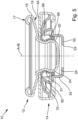
- the resilient retention member 62 passes the head 24, it narrows resiliently around the restriction 31 of the connection portion 20, returning to its initial position and formation, in which the resilient retention member 62 is in contact with the annular retention edge 64 of the female element.
- the resilient retention member 62 retains the connection portion 20 in the receiving seat 54 of the female element, preventing the release.
- the male element 12 and female element 14 in the buttoned configuration are preferably positioned one against the other, with the face 19 of the base 16 of the male element 12 in contact with the annular retention edge 64 of the female element.
- the resilient retention member 62 is in the region of the smaller diameter D3 of the seat thereof and, therefore, it cannot become wider or, at most, it can widen only slightly, significantly less than how much it can widen in the configuration of Figure 3 .
- a traction which is directed towards moving the two male 12 and female 14 elements apart from each other, as for conventional snap fasteners.
- the movement is normally in an axial direction and/or of the combined axial and rotational type.
- the traction which is applied brings about a localized compression of the portions 66 of the retention member which thereby allow the connection portion 20 to be released and therefore the fastener to be unbuttoned.
- the external diameter of the resilient retention member does not increase or at most increases slightly if play is provided between the resilient retention member and the seat thereof: the resilient retention member in fact remains, during the unbuttoning, in the zone of the receiving seat having a smaller diameter D3.
- the resistance which the resilient retention member opposes to the unbuttoning is therefore relatively high.
- the resilient retention member is pushed into a zone of the receiving seat having a greater diameter D4 and therefore the internal diameter and the external diameter of the resilient retention member both increase in order to allow easier insertion of the connection portion. The resistance which the resilient retention member opposes to the buttoning is therefore relatively high.
- connection elements 68 are more readily deformable than the portions 66, the force necessary to compress the portions 66 during the unbuttoning is significantly greater than the force necessary to move the portions 66 apart from each other during the buttoning.
- the fastener 10 is therefore characterized by a predefined unbuttoning force, which is defined as the force necessary to unbutton the fastener, and a predefined buttoning force, which is defined as the force necessary to button the fastener, and the unbuttoning force is greater than the buttoning force.
- the resilient retention member 62 is further preferably formed so that the connection elements 68 press against the tubular member 55.
- the connection elements 68 therefore contribute to maintaining the resilient retention member in the portion of the seat 60 with a smaller diameter D3. In this manner, optimum retention of the fastener is further ensured.
- Figure 6 shows a variant of a resilient retention member 62' which is generally similar to the resilient retention member 62 described above, wherein each portion 66' has a variable thickness, defining an inclined plane.
- the force necessary to deform the resilient retention member sufficiently to allow the buttoning is further divided as a result of the presence of inclined planes. The buttoning is thereby further facilitated.
- Another resilient retention member which is not illustrated may provide for portions which have a first rigidity and which are connected to each other in the same plane by connection elements having a second rigidity which is smaller than the first rigidity, as a result of a reduced thickness.
- Other embodiments may more generally comprise resilient retention members which are formed differently and which may widen to a greater diameter with respect to the minimum diameter D3 of the seat thereof, and which, in the rest configuration thereof, are sufficiently compressible to allow the unbuttoning of the fastener.
Landscapes
- Engineering & Computer Science (AREA)
- General Engineering & Computer Science (AREA)
- Mechanical Engineering (AREA)
- Slide Fasteners, Snap Fasteners, And Hook Fasteners (AREA)
Applications Claiming Priority (1)
| Application Number | Priority Date | Filing Date | Title |
|---|---|---|---|
| IT102023000018282A IT202300018282A1 (it) | 2023-09-06 | 2023-09-06 | Bottone a pressione perfezionato |
Publications (2)
| Publication Number | Publication Date |
|---|---|
| EP4520983A1 true EP4520983A1 (fr) | 2025-03-12 |
| EP4520983B1 EP4520983B1 (fr) | 2026-07-22 |
Family
ID=88585361
Family Applications (1)
| Application Number | Title | Priority Date | Filing Date |
|---|---|---|---|
| EP24198440.0A Active EP4520983B1 (fr) | 2023-09-06 | 2024-09-04 | Bouton-pression amélioré |
Country Status (2)
| Country | Link |
|---|---|
| EP (1) | EP4520983B1 (fr) |
| IT (1) | IT202300018282A1 (fr) |
Citations (5)
| Publication number | Priority date | Publication date | Assignee | Title |
|---|---|---|---|---|
| DE256068C (de) * | 1910-05-01 | 1913-01-29 | Zweiteilliger Knopfverschluß | |
| DE315088C (de) * | 1918-12-31 | 1919-10-29 | Druckknopf mit im Oberteil liegender Drahtfeder | |
| GB565289A (en) * | 1942-03-30 | 1944-11-03 | Scovill Manufacturing Co | One-way detachable snap fasteners |
| WO1997015207A1 (fr) | 1995-10-20 | 1997-05-01 | Cobra S.R.L. | Bouton-pression |
| ITUB20152665A1 (it) * | 2015-07-30 | 2017-01-30 | A M F Spa Unipersonale | Bottone a pressione, particolarmente per capi di abbigliamento e simili |
-
2023
- 2023-09-06 IT IT102023000018282A patent/IT202300018282A1/it unknown
-
2024
- 2024-09-04 EP EP24198440.0A patent/EP4520983B1/fr active Active
Patent Citations (5)
| Publication number | Priority date | Publication date | Assignee | Title |
|---|---|---|---|---|
| DE256068C (de) * | 1910-05-01 | 1913-01-29 | Zweiteilliger Knopfverschluß | |
| DE315088C (de) * | 1918-12-31 | 1919-10-29 | Druckknopf mit im Oberteil liegender Drahtfeder | |
| GB565289A (en) * | 1942-03-30 | 1944-11-03 | Scovill Manufacturing Co | One-way detachable snap fasteners |
| WO1997015207A1 (fr) | 1995-10-20 | 1997-05-01 | Cobra S.R.L. | Bouton-pression |
| ITUB20152665A1 (it) * | 2015-07-30 | 2017-01-30 | A M F Spa Unipersonale | Bottone a pressione, particolarmente per capi di abbigliamento e simili |
Also Published As
| Publication number | Publication date |
|---|---|
| EP4520983B1 (fr) | 2026-07-22 |
| IT202300018282A1 (it) | 2025-03-06 |
Similar Documents
| Publication | Publication Date | Title |
|---|---|---|
| EP1519662B1 (fr) | Bouton-pression utilise avec des tissus | |
| EP2832251B1 (fr) | Goujon de presse avec système anti-décrochage | |
| CN110612039B (zh) | 按扣 | |
| EP2709481A1 (fr) | Dispositif de fermeture à bouton-pression ou à encliquetage, en particulier pour articles d'habillement, et analogues | |
| US3783477A (en) | Snap fastener | |
| EP3405063B1 (fr) | Dispositif de fixation et système de fixation | |
| US2283125A (en) | Locking snap fastener | |
| US10030682B2 (en) | Two-part fastener | |
| EP4346495B1 (fr) | Bouton à pression amélioré | |
| US10986901B2 (en) | Snap button | |
| US9675143B2 (en) | Press stud with an anti-uncoupling system | |
| US3414949A (en) | Snap fastener with removable ornamental button | |
| US878550A (en) | Fastener. | |
| US1348011A (en) | Snap-fastener | |
| US1785825A (en) | Fastening installation | |
| US3785010A (en) | Pin-back buttons | |
| US20140053373A1 (en) | Buttons | |
| US2771652A (en) | Snap fastener socket | |
| US798708A (en) | Snap-fastener. | |
| CN109965461B (zh) | 卡合扣具 | |
| JP6147644B2 (ja) | ワンタッチボタン | |
| US484807A (en) | Glove-fastener | |
| US784258A (en) | Garment-fastener. | |
| IT202300018282A1 (it) | Bottone a pressione perfezionato | |
| CN119222231A (zh) | 用于装配物品的固定系统与相关的组装和拆卸方法 |
Legal Events
| Date | Code | Title | Description |
|---|---|---|---|
| PUAI | Public reference made under article 153(3) epc to a published international application that has entered the european phase |
Free format text: ORIGINAL CODE: 0009012 |
|
| STAA | Information on the status of an ep patent application or granted ep patent |
Free format text: STATUS: THE APPLICATION HAS BEEN PUBLISHED |
|
| AK | Designated contracting states |
Kind code of ref document: A1 Designated state(s): AL AT BE BG CH CY CZ DE DK EE ES FI FR GB GR HR HU IE IS IT LI LT LU LV MC ME MK MT NL NO PL PT RO RS SE SI SK SM TR |
|
| STAA | Information on the status of an ep patent application or granted ep patent |
Free format text: STATUS: REQUEST FOR EXAMINATION WAS MADE |
|
| 17P | Request for examination filed |
Effective date: 20250911 |
|
| GRAP | Despatch of communication of intention to grant a patent |
Free format text: ORIGINAL CODE: EPIDOSNIGR1 |
|
| STAA | Information on the status of an ep patent application or granted ep patent |
Free format text: STATUS: GRANT OF PATENT IS INTENDED |
|
| RIC1 | Information provided on ipc code assigned before grant |
Ipc: F16B 21/07 20060101AFI20260127BHEP Ipc: A44B 17/00 20060101ALI20260127BHEP |
|
| INTG | Intention to grant announced |
Effective date: 20260218 |
|
| GRAS | Grant fee paid |
Free format text: ORIGINAL CODE: EPIDOSNIGR3 |
|
| GRAA | (expected) grant |
Free format text: ORIGINAL CODE: 0009210 |
|
| STAA | Information on the status of an ep patent application or granted ep patent |
Free format text: STATUS: THE PATENT HAS BEEN GRANTED |
|
| AK | Designated contracting states |
Kind code of ref document: B1 Designated state(s): AL AT BE BG CH CY CZ DE DK EE ES FI FR GB GR HR HU IE IS IT LI LT LU LV MC ME MK MT NL NO PL PT RO RS SE SI SK SM TR |
|
| REG | Reference to a national code |
Ref country code: CH Ref legal event code: F10 Free format text: ST27 STATUS EVENT CODE: U-0-0-F10-F00 (AS PROVIDED BY THE NATIONAL OFFICE) Effective date: 20260722 Ref country code: GB Ref legal event code: FG4D |
|
| REG | Reference to a national code |
Ref country code: IE Ref legal event code: FG4D |
|
| REG | Reference to a national code |
Ref country code: DE Ref legal event code: R096 Ref document number: 602024006282 Country of ref document: DE |