EP4521004A2 - Moteur à combustion interne avec dispositif à taux de compression variable - Google Patents
Moteur à combustion interne avec dispositif à taux de compression variable Download PDFInfo
- Publication number
- EP4521004A2 EP4521004A2 EP24220133.3A EP24220133A EP4521004A2 EP 4521004 A2 EP4521004 A2 EP 4521004A2 EP 24220133 A EP24220133 A EP 24220133A EP 4521004 A2 EP4521004 A2 EP 4521004A2
- Authority
- EP
- European Patent Office
- Prior art keywords
- fluid
- channels
- cooling
- flow path
- piston rod
- Prior art date
- Legal status (The legal status is an assumption and is not a legal conclusion. Google has not performed a legal analysis and makes no representation as to the accuracy of the status listed.)
- Pending
Links
Images



Classifications
-
- F—MECHANICAL ENGINEERING; LIGHTING; HEATING; WEAPONS; BLASTING
- F01—MACHINES OR ENGINES IN GENERAL; ENGINE PLANTS IN GENERAL; STEAM ENGINES
- F01P—COOLING OF MACHINES OR ENGINES IN GENERAL; COOLING OF INTERNAL-COMBUSTION ENGINES
- F01P3/00—Liquid cooling
- F01P3/12—Arrangements for cooling other engine or machine parts
-
- F—MECHANICAL ENGINEERING; LIGHTING; HEATING; WEAPONS; BLASTING
- F01—MACHINES OR ENGINES IN GENERAL; ENGINE PLANTS IN GENERAL; STEAM ENGINES
- F01B—MACHINES OR ENGINES, IN GENERAL OR OF POSITIVE-DISPLACEMENT TYPE, e.g. STEAM ENGINES
- F01B31/00—Component parts, details or accessories not provided for in, or of interest apart from, other groups
- F01B31/14—Changing of compression ratio
-
- F—MECHANICAL ENGINEERING; LIGHTING; HEATING; WEAPONS; BLASTING
- F01—MACHINES OR ENGINES IN GENERAL; ENGINE PLANTS IN GENERAL; STEAM ENGINES
- F01M—LUBRICATING OF MACHINES OR ENGINES IN GENERAL; LUBRICATING INTERNAL COMBUSTION ENGINES; CRANKCASE VENTILATING
- F01M1/00—Pressure lubrication
- F01M1/06—Lubricating systems characterised by the provision therein of crankshafts or connecting rods with lubricant passageways, e.g. bores
-
- F—MECHANICAL ENGINEERING; LIGHTING; HEATING; WEAPONS; BLASTING
- F02—COMBUSTION ENGINES; HOT-GAS OR COMBUSTION-PRODUCT ENGINE PLANTS
- F02B—INTERNAL-COMBUSTION PISTON ENGINES; COMBUSTION ENGINES IN GENERAL
- F02B25/00—Engines characterised by using fresh charge for scavenging cylinders
- F02B25/02—Engines characterised by using fresh charge for scavenging cylinders using unidirectional scavenging
- F02B25/04—Engines having ports both in cylinder head and in cylinder wall near bottom of piston stroke
-
- F—MECHANICAL ENGINEERING; LIGHTING; HEATING; WEAPONS; BLASTING
- F02—COMBUSTION ENGINES; HOT-GAS OR COMBUSTION-PRODUCT ENGINE PLANTS
- F02B—INTERNAL-COMBUSTION PISTON ENGINES; COMBUSTION ENGINES IN GENERAL
- F02B75/00—Other engines
- F02B75/04—Engines with variable distances between pistons at top dead-centre positions and cylinder heads
-
- F—MECHANICAL ENGINEERING; LIGHTING; HEATING; WEAPONS; BLASTING
- F02—COMBUSTION ENGINES; HOT-GAS OR COMBUSTION-PRODUCT ENGINE PLANTS
- F02B—INTERNAL-COMBUSTION PISTON ENGINES; COMBUSTION ENGINES IN GENERAL
- F02B75/00—Other engines
- F02B75/04—Engines with variable distances between pistons at top dead-centre positions and cylinder heads
- F02B75/045—Engines with variable distances between pistons at top dead-centre positions and cylinder heads by means of a variable connecting rod length
-
- F—MECHANICAL ENGINEERING; LIGHTING; HEATING; WEAPONS; BLASTING
- F02—COMBUSTION ENGINES; HOT-GAS OR COMBUSTION-PRODUCT ENGINE PLANTS
- F02D—CONTROLLING COMBUSTION ENGINES
- F02D15/00—Varying compression ratio
- F02D15/02—Varying compression ratio by alteration or displacement of piston stroke
-
- F—MECHANICAL ENGINEERING; LIGHTING; HEATING; WEAPONS; BLASTING
- F16—ENGINEERING ELEMENTS AND UNITS; GENERAL MEASURES FOR PRODUCING AND MAINTAINING EFFECTIVE FUNCTIONING OF MACHINES OR INSTALLATIONS; THERMAL INSULATION IN GENERAL
- F16J—PISTONS; CYLINDERS; SEALINGS
- F16J1/00—Pistons; Trunk pistons; Plungers
- F16J1/09—Pistons; Trunk pistons; Plungers with means for guiding fluids
-
- F—MECHANICAL ENGINEERING; LIGHTING; HEATING; WEAPONS; BLASTING
- F16—ENGINEERING ELEMENTS AND UNITS; GENERAL MEASURES FOR PRODUCING AND MAINTAINING EFFECTIVE FUNCTIONING OF MACHINES OR INSTALLATIONS; THERMAL INSULATION IN GENERAL
- F16J—PISTONS; CYLINDERS; SEALINGS
- F16J1/00—Pistons; Trunk pistons; Plungers
- F16J1/10—Connection to driving members
- F16J1/14—Connection to driving members with connecting-rods, i.e. pivotal connections
- F16J1/16—Connection to driving members with connecting-rods, i.e. pivotal connections with gudgeon-pin; Gudgeon-pins
-
- F—MECHANICAL ENGINEERING; LIGHTING; HEATING; WEAPONS; BLASTING
- F16—ENGINEERING ELEMENTS AND UNITS; GENERAL MEASURES FOR PRODUCING AND MAINTAINING EFFECTIVE FUNCTIONING OF MACHINES OR INSTALLATIONS; THERMAL INSULATION IN GENERAL
- F16J—PISTONS; CYLINDERS; SEALINGS
- F16J7/00—Piston-rods
-
- F—MECHANICAL ENGINEERING; LIGHTING; HEATING; WEAPONS; BLASTING
- F01—MACHINES OR ENGINES IN GENERAL; ENGINE PLANTS IN GENERAL; STEAM ENGINES
- F01M—LUBRICATING OF MACHINES OR ENGINES IN GENERAL; LUBRICATING INTERNAL COMBUSTION ENGINES; CRANKCASE VENTILATING
- F01M1/00—Pressure lubrication
- F01M1/06—Lubricating systems characterised by the provision therein of crankshafts or connecting rods with lubricant passageways, e.g. bores
- F01M2001/066—Connecting rod with passageways
-
- F—MECHANICAL ENGINEERING; LIGHTING; HEATING; WEAPONS; BLASTING
- F01—MACHINES OR ENGINES IN GENERAL; ENGINE PLANTS IN GENERAL; STEAM ENGINES
- F01M—LUBRICATING OF MACHINES OR ENGINES IN GENERAL; LUBRICATING INTERNAL COMBUSTION ENGINES; CRANKCASE VENTILATING
- F01M1/00—Pressure lubrication
- F01M1/08—Lubricating systems characterised by the provision therein of lubricant jetting means
- F01M2001/086—Lubricating systems characterised by the provision therein of lubricant jetting means for lubricating gudgeon pins
-
- F—MECHANICAL ENGINEERING; LIGHTING; HEATING; WEAPONS; BLASTING
- F01—MACHINES OR ENGINES IN GENERAL; ENGINE PLANTS IN GENERAL; STEAM ENGINES
- F01P—COOLING OF MACHINES OR ENGINES IN GENERAL; COOLING OF INTERNAL-COMBUSTION ENGINES
- F01P3/00—Liquid cooling
- F01P2003/006—Liquid cooling the liquid being oil
-
- F—MECHANICAL ENGINEERING; LIGHTING; HEATING; WEAPONS; BLASTING
- F02—COMBUSTION ENGINES; HOT-GAS OR COMBUSTION-PRODUCT ENGINE PLANTS
- F02B—INTERNAL-COMBUSTION PISTON ENGINES; COMBUSTION ENGINES IN GENERAL
- F02B75/00—Other engines
- F02B75/32—Engines characterised by connections between pistons and main shafts and not specific to preceding main groups
-
- Y—GENERAL TAGGING OF NEW TECHNOLOGICAL DEVELOPMENTS; GENERAL TAGGING OF CROSS-SECTIONAL TECHNOLOGIES SPANNING OVER SEVERAL SECTIONS OF THE IPC; TECHNICAL SUBJECTS COVERED BY FORMER USPC CROSS-REFERENCE ART COLLECTIONS [XRACs] AND DIGESTS
- Y02—TECHNOLOGIES OR APPLICATIONS FOR MITIGATION OR ADAPTATION AGAINST CLIMATE CHANGE
- Y02T—CLIMATE CHANGE MITIGATION TECHNOLOGIES RELATED TO TRANSPORTATION
- Y02T10/00—Road transport of goods or passengers
- Y02T10/10—Internal combustion engine [ICE] based vehicles
- Y02T10/12—Improving ICE efficiencies
-
- Y—GENERAL TAGGING OF NEW TECHNOLOGICAL DEVELOPMENTS; GENERAL TAGGING OF CROSS-SECTIONAL TECHNOLOGIES SPANNING OVER SEVERAL SECTIONS OF THE IPC; TECHNICAL SUBJECTS COVERED BY FORMER USPC CROSS-REFERENCE ART COLLECTIONS [XRACs] AND DIGESTS
- Y02—TECHNOLOGIES OR APPLICATIONS FOR MITIGATION OR ADAPTATION AGAINST CLIMATE CHANGE
- Y02T—CLIMATE CHANGE MITIGATION TECHNOLOGIES RELATED TO TRANSPORTATION
- Y02T10/00—Road transport of goods or passengers
- Y02T10/10—Internal combustion engine [ICE] based vehicles
- Y02T10/30—Use of alternative fuels, e.g. biofuels
Definitions
- the present invention is related to an internal combustion engine, a method for running an internal combustion engine and a crosshead pin.
- the present invention preferably relates to an internal combustion engine like a large marine or ship engine or a stationary engine whose cylinders have an inner diameter of at least 200 mm.
- the engine preferably is a two-stroke engine or a two-stroke cross head engine.
- the engine can be a gas engine, a dual fuel or a multi fuel engine. Burning of liquid and or gaseous fuels in such engines is possible as well as self-igniting or forced igniting.
- the internal combustion engine can be a longitudinally flushed two-stroke engine.
- internal combustion engine also refers to large engines which can be operated not only in diesel mode, which is characterized by the self-ignition of the fuel, but also in Otto mode, which is characterized by the positive ignition of the fuel, or in mixtures of the two. Furthermore, the term internal combustion engine includes in particular dual-fuel engines and large engines in which the self-ignition of the fuel is used for the positive ignition of another fuel.
- Engine speed is preferably below 800 RPM, especially for 4-stroke engines, and more preferably below 200 RPM, especially for 2-stroke engines, which indicates the designation of low speed engines.
- Fuel can be diesel or marine diesel oils or heavy fuel oils or emulsions or slurries or methanol or ethanol as well as gases like liquid natural gas (LNG) liquid petrol gas (LPG) and so on.
- LNG liquid natural gas
- LPG liquid petrol gas
- LBG Liquefied Biogas
- biological fuels e.g. oil made from algae or seaweed
- ammonia e.g., ammonia
- hydrogen e.g., ammonia
- synthetic fuels from CO2 e.g. made by Power-To-Gas or Power-To-Liquid.
- the compression ratio i.e. the ratio between the volume of the cylinder and combustion chamber in the internal combustion engine at their maximum and minimum values, is an important parameter for the combustion, the thermal efficiency and for the exhaust gas emissions.
- the compression ratio is usually chosen to yield the best engine performance. Often the high load engine performance is the most relevant point for the choice. For optimal performance over the whole operating range a variable compression ratio would be desirable but due to complications with such a system a compromise is usually made defining a constant compression ratio.
- EP2687707A2 discloses large reciprocating piston combustion engines with a control apparatus for controlling the compression ratio of the reciprocating piston combustion machine.
- EP3805538A1 discloses a variable compression device for changing a compression ratio of an engine including a crosshead pin connected to the piston rod, the inside of the crosshead pin being provided with a fluid chamber in which the piston rod is moved in a direction of increasing the compression ratio by the pressure-increased working fluid being supplied into the fluid chamber.
- a pump increases the working fluid in pressure.
- VCR Variable Compression Ratio
- VCR Variable Compression Ratio
- the compression ratio can be adjusted during the normal engine running. The adjustment allows the optimization of the performance at part load without compromising the performance at high/full load.
- the compression ratio can be optimized for each fuel mode separately (high compression ratio for diesel mode, low compression ratio for gas mode). An optimization of the compression ratio depending on operational conditions (scavenge air temperature, methane number of fuel gas, wave load, etc.) is possible.
- Piston cooling oil heated up in the piston and discharged from the piston rod via the crosshead pin may heat up the crosshead pin and the hydraulic oil in the fluid chamber.
- the internal combustion engine has at least one cylinder.
- the internal combustion engine is a large vessel engine with at least one cylinder having an inner diameter of at least 200mm.
- the internal combustion engine may be a low pressure fuel gas engine or dual-fuel engine with.
- the internal combustion engine has at least one piston which is movably arranged within the cylinder.
- the internal combustion engine further comprises a rotatably arranged crankshaft, with the piston being in each case connected to a crosshead via a piston rod, and with a crosshead pin connected to the piston rod.
- the crosshead is in each case connected to the crankshaft via a connecting rod to drive the crankshaft.
- the engine comprises a variable compression ratio device for changing a compression ratio of an engine.
- the variable compression ratio device allows the volume above the piston at top dead centre to be changed.
- the variable compression ratio device comprises a fluid chamber arranged in the inside of the crosshead pin, in which the piston rod is moveable relative to a bottom of the fluid chamber.
- the movement may be induced by a pressure-increased working fluid, for example a working oil, being supplied into and out of the fluid chamber.
- the internal combustion engine may comprise a pumping device for transporting the working fluid into and out of the fluid chamber for changing the compression ratio.
- the piston rod may include an end portion with a larger diameter at the end part of the piston rod close to the crosshead pin.
- the outer peripheral surface of the lower end portion of the piston rod close to the crosshead pin may protrude outward in the radial direction, and thus the diameter of the end portion is greater than that of the middle part of the piston rod.
- Working fluid may be introduced into the fluid chamber below the end portion of the piston rod close to the crosshead pin.
- the end portion may comprise a sealing for holding the working fluid below the piston rod.
- the enlarged part of the end portion of the position rod may abut against an upper abutment member, for example an upper abutment face of the fluid chamber.
- the position rod may abut against the bottom of the fluid chamber.
- the piston rod comprises cooling channels.
- the cooling channels for guiding a cooling fluid are formed inside the piston rod and extend in a stroke direction of the piston.
- the crosshead pin comprises at least one first flow path for guiding a cooling fluid, for example a cooling oil, that is to be supplied to at least one of first cooling channels and at least one second flow path for guiding a cooling fluid that is to be discharged from at least one of second cooling channels.
- a cooling fluid for example a cooling oil
- the first flow path is arranged in a first distance to a bottom plane defined by the bottom of the fluid chamber and the second flow path is arranged in second distance to the bottom plane.
- the first distance is smaller than the second distance.
- the bottom of the fluid chamber is flat and the bottom plane comprises the bottom of the fluid chamber.
- the first flow path has a smaller distance to any working fluid which may be contained in the fluid chamber than the second flow path.
- the first flow path comprises a plurality of first channels, which are, preferably uniformly, arranged in a first cross-section of the crosshead pin and parallel to the bottom plane.
- the first flow path is for supplying a cooling fluid into the piston rod whereas the second flow path is for discharging the cooling fluid.
- cooling fluid transported via the first flow path is cooler than cooling fluid transported via the second flow path.
- the first flow path defines a cooling plane, which may shield working fluid in the fluid chamber from the second flow path.
- the internal combustion engine may comprise a further pumping device for transporting the cooling fluid into the first flow path and out of the second flow path.
- the second flow path may comprise at least one second channel arranged in a second cross-section of the crosshead pin parallel to the bottom plane.
- the second flow path may comprise a plurality of second channels, which preferably are uniformly arranged in the second cross-section.
- the first flow path may comprise a first number of first channels and the second flow path comprises second number of second channels.
- the first number may be greater than the second number.
- a greater number of channels may be distributed more evenly, such that the shielding effect of the first flow path is optimized.
- the diameter of first channels may be smaller than diameter of second channels.
- the channels Preferably have a circular cross section. Otherwise, at the least the axial diameter of first channels may be smaller than axial diameter of second channels.
- a certain rate of cooling fluid guided through channels with a small diameter can be evenly distributed over the cross section of the crosshead pin.
- An even distribution is especially advantageous for the inflowing cooling fluid as it shields the heat of the outflowing cooling fluid.
- the diameter of the second channels for the outflowing cooling fluid may be chosen larger.
- the distance between the first channels may be smaller than the distance between the second channels.
- the first flow path having small distances between the first channels forms a shielding plane with a well distributed cooling fluid.
- a first flow path with a great number of first channels having a small diameter and being arranged with a small distance provides for a homogeneous and therefore effective shielding plane.
- the diameter of the first channels may be between 5mm and 50mm, preferably between 10mm and 15mm. Too small diameters may cause an increasing hydraulic resistance and manufacturing costs may get too high.
- the number of first channels may be between 5 and 30, preferably between 7 and 15. The number may depend on the diameter of the first channels, preferably optimized with respect to hydraulic resistance and/or manufacturing costs, and the engine size.
- the distance between first channels may be between 10mm and 70mm, preferably between 20mm and 30mm.
- the distance corresponds to a wall thickness between the channels which provides for a sufficient stability and a convenient manufacturing.
- the distance may depend on the diameter of the first channels, preferably optimized with respect to hydraulic resistance and/or manufacturing costs, and the engine size.
- the crosshead pin may comprise a splitter ring.
- the splitter ring may be fixedly arranged with respect to the crosshead pin, in particular above or within the fluid chamber.
- the splitter ring may be arranged for defining a first annular cavity in fluid connection with at least one cooling channel for supplying cooling fluid to the piston rod.
- the splitter ring is arranged such that the first annular cavity is in fluid connection with the first flow path.
- the splitter ring is arranged for defining a second annular cavity being in fluid connection with at least one cooling channel for discharging cooling fluid from the piston and being in fluid connection with the second flow path.
- the first annular cavity and the second annular cavity are arranged around the piston rod, preferably around the end portion of the piston rod.
- the first annular cavity and the second annular cavity may be separated from each other fluid tightly. Exchange between the first annular cavity and the second annular cavity shall be reduced or prevented.
- the first annular cavity has a smaller distance to the bottom of fluid chamber than the second annular cavity.
- the splitter ring provides for a separation of introduced cooling fluid and discharged cooling fluid and prevents mixing of the introduced cooling fluid and the discharged cooling fluid.
- the introduced cooling fluid which typically has a lower temperature than the cooling fluid which is discharged from the piston rod may provide for shielding the heat of the discharged cooling fluid form the working fluid contained in the fluid chamber below the piston rod.
- At least a first seal member may be arranged on the outer peripheral surface of the end portion of the piston rod.
- the first seal member may at least partially be provided by a portion of the piston rod having an enlarged diameter and protruding radially outwards.
- the first annular cavity may be bounded by the first seal member in stroke direction on the lower side which is closer to the bottom of the fluid chamber and by the splitter ring on the upper side.
- a second seal member may be arranged on the outer peripheral surface of the end portion of the piston rod.
- the second seal member may at least partially be provided by a portion of the piston rod having an enlarged diameter and protruding radially outwards.
- the second annular cavity may be bounded by the splitter ring on the lower side which is closer to the bottom of the fluid chamber and by the second seal member on the upper side.
- the first and/or the second seal member may provide sliding ear faces between the piston rod and the crosshead pin.
- the pair of the first seal member and a second seal member may be arranged apart from each other in the stroke direction of the piston rod.
- the first seal member and a second seal member are arranged on the outer peripheral side surface of a large-diameter end portion of the piston rod.
- An annular groove may be formed between the first seal member and a second seal member. In the annular groove the exchange of cooling fluid takes place.
- the first annular cavity has a smaller axial extension than for smaller compression ratios.
- the second annular cavity has a larger axial extension than for smaller compression ratios.
- the splitter ring may comprise a seal member being in contact with the outer surface of the piston rod within the annular groove.
- the splitter ring may comprise at least two half rings or four quarter rings, preferably being screwed together.
- the splitter ring may be radially pressed to the wall of the fluid chamber and/or may be axially pressed into a groove or step within or above the fluid chamber.
- the splitter ring may be prevented from an axial movement, preferably in the direction towards the bottom of the fluid chamber, by an abutment face of the groove or step.
- the splitter ring may be fixed by a locking device, for example a cylindrical shaped spring element, to avoid a rotational and/or axial movement.
- a locking device for example a cylindrical shaped spring element
- the splitter ring may be prevented from an axial movement, preferably in the direction away from the bottom of the fluid chamber, by an abutment face of the spring element.
- the piston rod may comprises at least one supply channel for supplying cooling fluid into cooling channels and/or may comprise at least one discharge channel for discharging cooling fluid from cooling channels.
- the supply channel is in fluid connection with the first annular cavity and/or the discharge channel is in fluid connection to the second annular cavity defined by the splitter ring.
- the supply channel has a smaller distance to the bottom of fluid chamber than the discharge channel.
- the first flow path, the first annular chamber and the supply channel form a supply system
- the second flow path, the second annular chamber and the discharge channel form a discharge system, wherein the supply system is arranged in a closer distance to the bottom plane than the discharge system.
- the working fluid thus is completely shielded from the heat of the discharged cooling fluid by the supply system transporting cooling fluid of a lower temperature.
- the internal combustion engine may comprise at least one first knee lever connected to the crosshead pin for providing and/or releasing the cooling fluid.
- the first knee lever may comprise pipes which are fluidly connected to the first and to the second flow path.
- the internal combustion engine may comprise at least one second knee lever connected to the crosshead pin for providing and/or releasing the working fluid.
- the second knee lever may comprise at least one pipe which is fluidly connected to the fluid chamber.
- a method for running an internal combustion engine as described above comprises the following steps.
- a pressure-increased working fluid is provided in a fluid chamber in which the piston rod is moveable relative to a bottom of the fluid chamber.
- the piston rod moves upwardly in a direction away from the bottom of the fluid chamber to increase the compression ratio.
- the piston is cooled by guiding a cooling fluid through cooling channels arranged in the piston rod.
- the cooling fluid is supplied to at least one of the cooling channels through at least one first flow path in the crosshead pin and the cooling fluid is discharged from at least one of the cooling channels through at least one second flow path in the crosshead pin.
- the supplied cooling fluid shields the working fluid from the heat of the discharged cooling fluid.
- Shielding may be achieved by the discharged cooling fluid being guided in greater distance to the working fluid in the fluid chamber than the supplied cooling fluid.
- the cooling fluid may be supplied to at least one of the cooling channels in an area between the bottom plane and the area where the cooling fluid is discharged from the at least one of the cooling channels.
- the working fluid may keep a temperature below 70°C, preferably below 55°C, more preferably below 45°C.
- the piston rod may be moved relative to the bottom of the fluid chamber by supplying working fluid into the fluid chamber or discharging supplying working fluid from the fluid chamber.
- a crosshead pin for an internal combustion engine comprises a fluid chamber for guiding a piston rod which is moveable relative to a bottom of the fluid chamber.
- the fluid chamber may receive a working fluid.
- the crosshead pin comprises at least one first flow path for guiding a cooling fluid that is to be supplied to at least one of the cooling channels of the piston rod and at least one second flow path for guiding a cooling fluid that is to be discharged from at least one of the cooling channels of the piston rod.
- the first flow path is arranged in a first distance to the bottom plane defined by the bottom of the fluid chamber and the second flow path is arranged in a second distance to the bottom plane.
- the first distance is smaller than the second distance.
- the first flow path comprises first channels, preferably uniformly, arranged in a first cross-section of the crosshead pin parallel to the bottom plane.
- Figure 1 shows a schematic view of an internal combustion engine 100 having a cylinder 1.
- the engine 100 has a piston 6 which is movably arranged within the cylinder 1.
- the piston 6 is connected to a crosshead pin 11 arranged in a crosshead 8 via a piston rod 7.
- the crosshead 8 is connected to a crankshaft 2 via a connecting rod 9 to drive the crankshaft 2.
- the engine 100 comprises a variable compression ratio device 10 for changing a compression ratio of an engine.
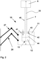
- variable compression ratio device 10 comprises a fluid chamber 12 arranged in the inside of the crosshead pin 11.
- the piston rod 7 is moveable relative to a bottom 13 of the fluid chamber 12 by a pressure-increased working fluid being supplied into the fluid chamber 12.
- the end portion 44 of the piston rod 7 has an enlarged radial diameter as compared to the middle portion 45 of the piston rod.
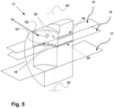
- the crosshead pin 11 comprises a first flow path 15 for guiding a cooling fluid that is to be supplied to first cooling channels 14a and at least one second flow path 16 for guiding a cooling fluid that is to be discharged from a second cooling channel 14b.
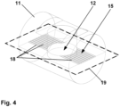
- the first flow path 15 comprises a plurality of first channels 18, which are uniformly arranged in a first cross-section 19 of the crosshead pin 11 parallel to the bottom plane 17.
- the first channels 18 are open towards the fluid chamber 12.
- the first seal member 45 of the piston rod 7 prevents the cooling fluid from mixing with the working fluid.
- the distance d3 between the first channels 18 is smaller than the distance d4 between the second channels 20.
- the cooling fluid is supplied to at least one of the cooling channels 14a (see figure 3 ) in an area 29 between the bottom plane 17 and the area 30 where the cooling fluid is discharged from the cooling channel 14b (see figure 3 ).
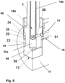
- Figure 6 shows a schematic partial sectional view of the crosshead pin 11 and the piston rod 7.
- the end portion 44 of the piston rod comprises a first seal member 45 and a second seal member 46 provided by portions of the piston rod 7 having an enlarged diameter and protruding radially outwards.
- the crosshead pin 11 comprises a splitter ring 22.
- the splitter ring 22 defines a first annular cavity 23 below the splitter ring 22.
- the first annular cavity 23 is in fluid connection with a cooling channel 14a for supplying cooling fluid to the piston 6 via supply channels 25.
- the first annular cavity 23 is also in fluid connection with the first flow path 15.
- the splitter ring 22 also defines a second annular cavity 24 above the splitter ring 22.
- the second annular cavity 24 is in fluid connection with at least one cooling channel 14b for discharging cooling fluid from the piston rod 7 via discharge channels 26.
- the second annular cavity 24 is also in fluid connection with the second flow path 16.
- the splitter ring 22 provides for a fluid tight separation between the first annular cavity 23 and the second annular cavity 24.
- the first annular cavity 23 is arranged below the second annular cavity 24 and has a smaller distance to the bottom 13 of fluid chamber 12 than second annular cavity 24.
- the first annular cavity 23 is limited by the first seal member 45 in stroke direction on the lower side which is closer to the bottom 13 and by the splitter ring 22 on the upper side.
- the second annular cavity 24 is limited by the second seal member 46 in stroke direction on the upper side by the splitter ring 22 on the lower side.
- Figure 7 shows a further schematic partial sectional view of the crosshead pin 11.
- the splitter ring 22 is fixed to the crosshead pin 11 by a locking device, in this case a cylindrical shaped spring element 31.
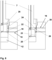
- Figure 8 shows half sectional views of the crosshead pin 11 with the piston rod 7 in two different positions.
- the supply system comprising the first flow path 15, the first annular cavity 23 and the supply channels 25 is arranged below the discharge system comprising the second flow path 16, the second annular cavity 24 and the discharge channel 26 for all axial positions of the piston rod 7.
Landscapes
- Engineering & Computer Science (AREA)
- General Engineering & Computer Science (AREA)
- Mechanical Engineering (AREA)
- Chemical & Material Sciences (AREA)
- Combustion & Propulsion (AREA)
- Output Control And Ontrol Of Special Type Engine (AREA)
- Control Of Vehicle Engines Or Engines For Specific Uses (AREA)
- Pistons, Piston Rings, And Cylinders (AREA)
Priority Applications (1)
| Application Number | Priority Date | Filing Date | Title |
|---|---|---|---|
| EP24220133.3A EP4521004A3 (fr) | 2021-10-18 | 2021-10-18 | Moteur à combustion interne avec dispositif à taux de compression variable |
Applications Claiming Priority (2)
| Application Number | Priority Date | Filing Date | Title |
|---|---|---|---|
| EP24220133.3A EP4521004A3 (fr) | 2021-10-18 | 2021-10-18 | Moteur à combustion interne avec dispositif à taux de compression variable |
| EP21203071.2A EP4166769B1 (fr) | 2021-10-18 | 2021-10-18 | Moteur à combustion interne doté d'un dispositif à taux de compression variable |
Related Parent Applications (2)
| Application Number | Title | Priority Date | Filing Date |
|---|---|---|---|
| EP21203071.2A Division-Into EP4166769B1 (fr) | 2021-10-18 | 2021-10-18 | Moteur à combustion interne doté d'un dispositif à taux de compression variable |
| EP21203071.2A Division EP4166769B1 (fr) | 2021-10-18 | 2021-10-18 | Moteur à combustion interne doté d'un dispositif à taux de compression variable |
Publications (2)
| Publication Number | Publication Date |
|---|---|
| EP4521004A2 true EP4521004A2 (fr) | 2025-03-12 |
| EP4521004A3 EP4521004A3 (fr) | 2025-04-09 |
Family
ID=78528603
Family Applications (2)
| Application Number | Title | Priority Date | Filing Date |
|---|---|---|---|
| EP24220133.3A Pending EP4521004A3 (fr) | 2021-10-18 | 2021-10-18 | Moteur à combustion interne avec dispositif à taux de compression variable |
| EP21203071.2A Active EP4166769B1 (fr) | 2021-10-18 | 2021-10-18 | Moteur à combustion interne doté d'un dispositif à taux de compression variable |
Family Applications After (1)
| Application Number | Title | Priority Date | Filing Date |
|---|---|---|---|
| EP21203071.2A Active EP4166769B1 (fr) | 2021-10-18 | 2021-10-18 | Moteur à combustion interne doté d'un dispositif à taux de compression variable |
Country Status (5)
| Country | Link |
|---|---|
| EP (2) | EP4521004A3 (fr) |
| JP (1) | JP7815069B2 (fr) |
| KR (1) | KR102898559B1 (fr) |
| CN (1) | CN115992756A (fr) |
| DK (1) | DK4166769T3 (fr) |
Citations (2)
| Publication number | Priority date | Publication date | Assignee | Title |
|---|---|---|---|---|
| EP2687707A2 (fr) | 2012-07-17 | 2014-01-22 | Wärtsilä Schweiz AG | Moteur à combustion à piston alternatif important, appareil de commande et procédé de commande d'un tel moteur |
| EP3805538A1 (fr) | 2018-05-25 | 2021-04-14 | IHI Corporation | Dispositif de compression variable et système de moteur |
Family Cites Families (2)
| Publication number | Priority date | Publication date | Assignee | Title |
|---|---|---|---|---|
| JP6946977B2 (ja) * | 2017-11-28 | 2021-10-13 | 株式会社Ihi | 可変圧縮装置及びエンジンシステム |
| JP7139702B2 (ja) * | 2018-06-11 | 2022-09-21 | 株式会社Ihi | 圧縮比可変機構 |
-
2021
- 2021-10-18 EP EP24220133.3A patent/EP4521004A3/fr active Pending
- 2021-10-18 EP EP21203071.2A patent/EP4166769B1/fr active Active
- 2021-10-18 DK DK21203071.2T patent/DK4166769T3/da active
-
2022
- 2022-09-07 JP JP2022141825A patent/JP7815069B2/ja active Active
- 2022-09-22 CN CN202211155718.9A patent/CN115992756A/zh active Pending
- 2022-10-12 KR KR1020220130323A patent/KR102898559B1/ko active Active
Patent Citations (2)
| Publication number | Priority date | Publication date | Assignee | Title |
|---|---|---|---|---|
| EP2687707A2 (fr) | 2012-07-17 | 2014-01-22 | Wärtsilä Schweiz AG | Moteur à combustion à piston alternatif important, appareil de commande et procédé de commande d'un tel moteur |
| EP3805538A1 (fr) | 2018-05-25 | 2021-04-14 | IHI Corporation | Dispositif de compression variable et système de moteur |
Also Published As
| Publication number | Publication date |
|---|---|
| JP2023060819A (ja) | 2023-04-28 |
| DK4166769T3 (da) | 2025-06-23 |
| CN115992756A (zh) | 2023-04-21 |
| KR20230055365A (ko) | 2023-04-25 |
| EP4166769B1 (fr) | 2025-04-09 |
| EP4521004A3 (fr) | 2025-04-09 |
| JP7815069B2 (ja) | 2026-02-17 |
| KR102898559B1 (ko) | 2025-12-09 |
| EP4166769A1 (fr) | 2023-04-19 |
Similar Documents
| Publication | Publication Date | Title |
|---|---|---|
| EP3296597B1 (fr) | Moteur à crosse | |
| KR102865091B1 (ko) | 내연 엔진 | |
| DK181316B1 (en) | A large turbocharged two-stroke uniflow crosshead dual fuel internal combustion engine | |
| EP3889472B1 (fr) | Ensemble de segments de piston | |
| JP6675281B2 (ja) | 内燃機関 | |
| US20210071550A1 (en) | Variable compression ratio mechanism | |
| EP4166769B1 (fr) | Moteur à combustion interne doté d'un dispositif à taux de compression variable | |
| JP3251442U (ja) | 可変圧縮比(vcr)機関 | |
| EP4155526A1 (fr) | Buse d'admission de carburant | |
| KR102323480B1 (ko) | 내연 엔진 | |
| KR102646089B1 (ko) | 내연 엔진 | |
| JP7649112B2 (ja) | 大型ディーゼルエンジンのシリンダ用シリンダカバー及びシリンダカバーの修理方法 | |
| WO2018163245A1 (fr) | Moteur à deux temps du type à balayage en équicourant | |
| JP2026010677A (ja) | 大型エンジン及び大型エンジン用の燃料を加圧するための燃料ブースタユニット | |
| KR102833021B1 (ko) | 대형 디젤 엔진을 작동시키기 위한 방법 및 대형 디젤 엔진 | |
| JP2023059836A (ja) | 長手方向掃気式大型ディーゼル・エンジン | |
| WO2019107434A1 (fr) | Dispositif de compression variable et système de moteur | |
| WO2017094616A1 (fr) | Moteur à gaz | |
| JP2025185720A (ja) | 大型エンジン用のシリンダカバー構成体および大型エンジン | |
| JP2023077405A (ja) | 内燃エンジン | |
| JP2020079599A (ja) | 内燃機関 |
Legal Events
| Date | Code | Title | Description |
|---|---|---|---|
| PUAI | Public reference made under article 153(3) epc to a published international application that has entered the european phase |
Free format text: ORIGINAL CODE: 0009012 |
|
| STAA | Information on the status of an ep patent application or granted ep patent |
Free format text: STATUS: THE APPLICATION HAS BEEN PUBLISHED |
|
| REG | Reference to a national code |
Ref country code: DE Ref legal event code: R079 Free format text: PREVIOUS MAIN CLASS: F16J0007000000 Ipc: F02B0075040000 |
|
| PUAL | Search report despatched |
Free format text: ORIGINAL CODE: 0009013 |
|
| AC | Divisional application: reference to earlier application |
Ref document number: 4166769 Country of ref document: EP Kind code of ref document: P |
|
| AK | Designated contracting states |
Kind code of ref document: A2 Designated state(s): AL AT BE BG CH CY CZ DE DK EE ES FI FR GB GR HR HU IE IS IT LI LT LU LV MC MK MT NL NO PL PT RO RS SE SI SK SM TR |
|
| AK | Designated contracting states |
Kind code of ref document: A3 Designated state(s): AL AT BE BG CH CY CZ DE DK EE ES FI FR GB GR HR HU IE IS IT LI LT LU LV MC MK MT NL NO PL PT RO RS SE SI SK SM TR |
|
| RIC1 | Information provided on ipc code assigned before grant |
Ipc: F01P 3/00 20060101ALN20250305BHEP Ipc: F16J 7/00 20060101ALI20250305BHEP Ipc: F16J 1/16 20060101ALI20250305BHEP Ipc: F16J 1/09 20060101ALI20250305BHEP Ipc: F02B 25/04 20060101ALI20250305BHEP Ipc: F01M 1/08 20060101ALI20250305BHEP Ipc: F01B 31/14 20060101ALI20250305BHEP Ipc: F01M 1/06 20060101ALI20250305BHEP Ipc: F01P 3/12 20060101ALI20250305BHEP Ipc: F16J 1/14 20060101ALI20250305BHEP Ipc: F02D 15/02 20060101ALI20250305BHEP Ipc: F02B 75/32 20060101ALI20250305BHEP Ipc: F02B 75/04 20060101AFI20250305BHEP |
|
| STAA | Information on the status of an ep patent application or granted ep patent |
Free format text: STATUS: REQUEST FOR EXAMINATION WAS MADE |
|
| 17P | Request for examination filed |
Effective date: 20250820 |
|
| STAA | Information on the status of an ep patent application or granted ep patent |
Free format text: STATUS: EXAMINATION IS IN PROGRESS |
|
| 17Q | First examination report despatched |
Effective date: 20260312 |
|
| GRAP | Despatch of communication of intention to grant a patent |
Free format text: ORIGINAL CODE: EPIDOSNIGR1 |
|
| STAA | Information on the status of an ep patent application or granted ep patent |
Free format text: STATUS: GRANT OF PATENT IS INTENDED |
|
| RIC1 | Information provided on ipc code assigned before grant |
Ipc: F02B 75/04 20060101AFI20260630BHEP Ipc: F02B 75/32 20060101ALI20260630BHEP Ipc: F02D 15/02 20060101ALI20260630BHEP Ipc: F16J 1/14 20060101ALI20260630BHEP Ipc: F01P 3/12 20060101ALI20260630BHEP Ipc: F01M 1/06 20060101ALI20260630BHEP Ipc: F01B 31/14 20060101ALI20260630BHEP Ipc: F01M 1/08 20060101ALI20260630BHEP Ipc: F02B 25/04 20060101ALI20260630BHEP Ipc: F16J 1/09 20060101ALI20260630BHEP Ipc: F16J 1/16 20060101ALI20260630BHEP Ipc: F16J 7/00 20060101ALI20260630BHEP Ipc: F01P 3/00 20060101ALN20260630BHEP |