EP4521005A1 - Système d'eau potable et d'eau sanitaire et soupape d'arrêt pour celui-ci - Google Patents
Système d'eau potable et d'eau sanitaire et soupape d'arrêt pour celui-ci Download PDFInfo
- Publication number
- EP4521005A1 EP4521005A1 EP24199111.6A EP24199111A EP4521005A1 EP 4521005 A1 EP4521005 A1 EP 4521005A1 EP 24199111 A EP24199111 A EP 24199111A EP 4521005 A1 EP4521005 A1 EP 4521005A1
- Authority
- EP
- European Patent Office
- Prior art keywords
- line
- branch
- side connection
- ring
- actuator
- Prior art date
- Legal status (The legal status is an assumption and is not a legal conclusion. Google has not performed a legal analysis and makes no representation as to the accuracy of the status listed.)
- Pending
Links
Images


Classifications
-
- F—MECHANICAL ENGINEERING; LIGHTING; HEATING; WEAPONS; BLASTING
- F16—ENGINEERING ELEMENTS AND UNITS; GENERAL MEASURES FOR PRODUCING AND MAINTAINING EFFECTIVE FUNCTIONING OF MACHINES OR INSTALLATIONS; THERMAL INSULATION IN GENERAL
- F16K—VALVES; TAPS; COCKS; ACTUATING-FLOATS; DEVICES FOR VENTING OR AERATING
- F16K11/00—Multiple-way valves, e.g. mixing valves; Pipe fittings incorporating such valves
- F16K11/02—Multiple-way valves, e.g. mixing valves; Pipe fittings incorporating such valves with all movable sealing faces moving as one unit
- F16K11/08—Multiple-way valves, e.g. mixing valves; Pipe fittings incorporating such valves with all movable sealing faces moving as one unit comprising only taps or cocks
- F16K11/085—Multiple-way valves, e.g. mixing valves; Pipe fittings incorporating such valves with all movable sealing faces moving as one unit comprising only taps or cocks with cylindrical plug
- F16K11/0853—Multiple-way valves, e.g. mixing valves; Pipe fittings incorporating such valves with all movable sealing faces moving as one unit comprising only taps or cocks with cylindrical plug having all the connecting conduits situated in a single plane perpendicular to the axis of the plug
-
- E—FIXED CONSTRUCTIONS
- E03—WATER SUPPLY; SEWERAGE
- E03B—INSTALLATIONS OR METHODS FOR OBTAINING, COLLECTING, OR DISTRIBUTING WATER
- E03B7/00—Water main or service pipe systems
- E03B7/07—Arrangement of devices, e.g. filters, flow controls, measuring devices, siphons or valves, in the pipe systems
- E03B7/075—Arrangement of devices for control of pressure or flow rate
-
- E—FIXED CONSTRUCTIONS
- E03—WATER SUPPLY; SEWERAGE
- E03B—INSTALLATIONS OR METHODS FOR OBTAINING, COLLECTING, OR DISTRIBUTING WATER
- E03B7/00—Water main or service pipe systems
- E03B7/07—Arrangement of devices, e.g. filters, flow controls, measuring devices, siphons or valves, in the pipe systems
- E03B7/08—Arrangement of draining devices, e.g. manual shut-off valves
-
- E—FIXED CONSTRUCTIONS
- E03—WATER SUPPLY; SEWERAGE
- E03B—INSTALLATIONS OR METHODS FOR OBTAINING, COLLECTING, OR DISTRIBUTING WATER
- E03B7/00—Water main or service pipe systems
- E03B7/04—Domestic or like local pipe systems
-
- E—FIXED CONSTRUCTIONS
- E03—WATER SUPPLY; SEWERAGE
- E03B—INSTALLATIONS OR METHODS FOR OBTAINING, COLLECTING, OR DISTRIBUTING WATER
- E03B7/00—Water main or service pipe systems
- E03B7/04—Domestic or like local pipe systems
- E03B7/045—Domestic or like local pipe systems diverting initially cold water in warm water supply
-
- E—FIXED CONSTRUCTIONS
- E03—WATER SUPPLY; SEWERAGE
- E03B—INSTALLATIONS OR METHODS FOR OBTAINING, COLLECTING, OR DISTRIBUTING WATER
- E03B7/00—Water main or service pipe systems
- E03B7/09—Component parts or accessories
-
- E—FIXED CONSTRUCTIONS
- E03—WATER SUPPLY; SEWERAGE
- E03C—DOMESTIC PLUMBING INSTALLATIONS FOR FRESH WATER OR WASTE WATER; SINKS
- E03C1/00—Domestic plumbing installations for fresh water or waste water; Sinks
- E03C1/02—Plumbing installations for fresh water
- E03C1/021—Devices for positioning or connecting of water supply lines
- E03C1/023—Devices for positioning or connecting of water supply lines with flow distribution, e.g. diverters
-
- F—MECHANICAL ENGINEERING; LIGHTING; HEATING; WEAPONS; BLASTING
- F16—ENGINEERING ELEMENTS AND UNITS; GENERAL MEASURES FOR PRODUCING AND MAINTAINING EFFECTIVE FUNCTIONING OF MACHINES OR INSTALLATIONS; THERMAL INSULATION IN GENERAL
- F16K—VALVES; TAPS; COCKS; ACTUATING-FLOATS; DEVICES FOR VENTING OR AERATING
- F16K11/00—Multiple-way valves, e.g. mixing valves; Pipe fittings incorporating such valves
- F16K11/02—Multiple-way valves, e.g. mixing valves; Pipe fittings incorporating such valves with all movable sealing faces moving as one unit
- F16K11/08—Multiple-way valves, e.g. mixing valves; Pipe fittings incorporating such valves with all movable sealing faces moving as one unit comprising only taps or cocks
- F16K11/085—Multiple-way valves, e.g. mixing valves; Pipe fittings incorporating such valves with all movable sealing faces moving as one unit comprising only taps or cocks with cylindrical plug
- F16K11/0856—Multiple-way valves, e.g. mixing valves; Pipe fittings incorporating such valves with all movable sealing faces moving as one unit comprising only taps or cocks with cylindrical plug having all the connecting conduits situated in more than one plane perpendicular to the axis of the plug
Definitions
- the present invention relates to a drinking or service water system with a transfer point from a public drinking water supply network and with at least one floor or riser pipe line and, as a rule, several lines arranged one behind the other in the direction of extension of the line and each leading to at least one withdrawal point, which lines branch off from the line.
- This previously known system is based on the idea that various consumers can be supplied via a single line.
- This line is a floor or riser line.
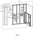
- the riser line typically runs through several floors and is generally strictly straight. The same applies to the floor line. This runs horizontally on one floor and supplies several consecutive wet rooms or apartments. In order to ensure the lowest possible loss of drinking and service water to one of the consumers, unnecessary diversions from the transfer point to the consumer are usually avoided.
- each of the lines is laid as straight as possible. This enables the respective consumers to be supplied with a good line pressure. This allows relatively high volume flows to be achieved at the respective consumer.
- a ring main With regard to drinking water hygiene, it is preferable to connect at least one consumer, preferably several consumers, for example, in a wet room, via a ring main.
- This ring main leads from the line via an outlet opening and is returned to the line via an inlet opening.
- a flow resistance element is provided in the branch between the inlet and outlet openings. This flow resistance element causes a certain flow through the ring main when water flows through the branch when water is drawn from a consumer located downstream of the corresponding ring main. The flow resistance can create a Venturi effect at the inlet opening.
- the flow resistance element can also simply increase the flow resistance in the branch to the extent that a certain partial flow flows through the ring main, which is significantly longer and therefore has a higher flow resistance than the section of the branch between the outlet opening and the inlet opening.
- the flow through the ring main is parallel to the branch and is thus flushed.
- Ring lines within the meaning of the present invention can also be understood as an annular piping in which a hot water supply line leads from an outlet opening of a hot water supply line to at least one, usually to several, consumers, which is returned via an inlet opening and connected via this to another line, which is referred to below as a circulation line.
- a hot water supply line leads from an outlet opening of a hot water supply line to at least one, usually to several, consumers, which is returned via an inlet opening and connected via this to another line, which is referred to below as a circulation line.
- Such piping is usually implemented to supply a wet room with a hot water supply line laid within the wet room and a hot water circulation line laid within the wet room, into which the hot water supply line usually merges within the wet room and which has a smaller nominal diameter than the hot water supply line.
- shut-off valves The installation effort for these two shut-off valves is considerable. In addition, the user is often unable to trace the respective valve position. Incorrect use of the shut-off valves can lead to insufficient flow or stagnation, particularly within the ring main.
- One of the shut-off valves can be closed and the other open without this necessarily leading to a perceived malfunction, since in this case the consumer intended in the ring main is supplied through the open shut-off valve. It makes no difference whether the opening in the ring main that enables the supply to the consumer is the inlet opening or the outlet opening. The pressure difference that occurs when the consumer draws water from the water supply always leads to a flow of water towards the consumer, so that water can be drawn off via this opening.
- the outlet and inlet openings formed by such a ring line flushing valve are adapted in terms of their relative distances to branch-side connections arranged on a housing of the shut-off valve, which accommodates and movably supports the actuator.
- a direct connection can thus be made between these branch-side connections and the outlet opening or the inlet opening, for example by means of fittings or mutually associated screw connections.
- the actuator is adjusted in such a way that at least the positions known from the prior art are possible, in which the ring line can be flowed through via the outlet opening and the inlet opening with the lowest possible flow resistance within the shut-off valve or the ring line is shut off from the branch. These two valve positions can usually be achieved by operating the single actuator of the shut-off valve. This simplifies handling.
- shut-off valve only one access point for the shut-off valve needs to be created from the outside, which improves the aesthetic requirements of the space providing access to the shut-off valve. Since only a single shut-off valve needs to be operated or set by the user, the respective operating status of the shut-off valve can be communicated to the user through appropriate markings on the housing and/or the actuator. Misuse is thus largely eliminated. The respective operating status of the shut-off valve is immediately apparent to the user.
- the actuator due to its design and arrangement in the housing, preferably enables further operating positions, namely a first one-sided operating position in which the first flow path is continuous and the second flow path is blocked, and a second one-sided operating position in which the second flow path is continuous and the first flow path is blocked.
- Each of these one-sided operating positions enables functional checks and cleaning measures to be carried out within the ring main or a specific section of the ring main, since the incoming flow can only flow from the branch into the ring main from one direction.
- the actuator can be arranged and configured in the housing such that, in a ring line bypass position of the actuator, a second bypass path is formed in the housing, connecting the first ring line-side connection to the second ring line-side connection. In this ring line bypass position, the first and second branch-side connections are blocked.
- a ring line bypass position can be useful for the purpose of functional testing of the ring line as such or for cleaning measures within the ring line.
- the present invention enables various designs, each of which allows for reduced installation space in one dimension. Both variants are based on the actuator being cylindrical and pivotably accommodated in the housing.
- the connections and/or formations of the actuator which form various passages between the connections depending on the position of the actuator, are arranged essentially in a plane extending transversely to a pivot axis of the actuator. In this plane, the corresponding connections are provided distributed around the circumference of the housing.
- the housing accordingly has a relatively large base area with a shallow depth. Depth here is understood to be the extent along the pivot axis. Such a design can be useful for a relatively thin wall that is intended to accommodate the shut-off valve.
- the actuator has two through-bores arranged one behind the other in a direction extending along the pivot axis of the actuator, which form the first flow path and the second flow path, respectively.
- the first branch-side connection can be provided behind or in front of the second branch-side connection in a direction extending along the pivot axis of the actuator.
- a corresponding arrangement is preferably specified for the two ring line-side connections.
- connection to the ring line or the connections to the branch and/or the when viewed from above the wall, the through-holes provided for forming the first and second flow paths are arranged one behind the other, corresponding to a view of the pivot axis of the actuator.
- the corresponding connections or through-holes are also arranged strictly one behind the other in the direction of this pivot axis.
- a branch-side connection is arranged directly in front of or behind the second branch-side connection along the pivot axis.
- the branch-side connections are preferably arranged diametrically opposite the ring line-side connections, so that the through-holes can be recessed as straight holes within the actuator, thereby reducing the flow resistance within the shut-off valve.
- the actuator comprises an expansion element associated with at least one of the flow paths.
- This expansion element allows the flow through the corresponding flow path to be throttled depending on the temperature.
- the expansion element is exposed to the temperature of the flowing drinking or service water. It can thus limit the flow through the shut-off valve depending on the temperature.
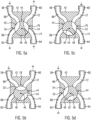
- Figure 4 shows a housing 42 of the shut-off valve 18/20, in which an actuator 44 is pivotably mounted about a pivot axis 46.
- the actuator 44 has a substantially cylindrical valve body 48 and an actuating pin 50 projecting centrally therefrom.
- the Figure 5a clarifies the operating position.
- the first concave trough 52 connects flow sections 66, 68 formed in the housing 42 to form a first flow path 70, which connects the first branch-side connection 58 to the first ring-line-side section 62.
- the second concave trough 54 connects corresponding flow sections 72, 74 to form a second flow path 76.
- the ring line 10 can be flowed through, as in the prior art, with the full-flow shut-off valves open.
- the Figure 5b illustrates a bypass position of the actuator 44.
- the actuator 44 is opposite the operating position according to Figure 5a pivoted clockwise by approximately 80°.
- the first concave trough 52 connects the flow section 66 to the flow section 72, thereby forming a first bypass path that connects the first branch-side connection 58 to the second branch-side connection 60.
- the two ring line-side connections 62, 64 are blocked by the actuator 44.
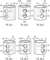
- a cylindrical actuator 44 is pivotably mounted about a pivot axis 46 in a housing 42, which is schematically shown to be cylindrical on the outer circumference.
- the first strand-side connection 58 and the second strand-side connection 60 are provided one above the other in the direction of extension of the pivot axis 46 (cf. Figure 6a.3 ).
- the first ring line-side connection 62 and the second ring line-side connection 64 are provided one above the other (cf. Figure 6a.1 ).
- the Figure 6a.2 shows through holes 80, 82, which are also arranged one above the other in the direction of extension of the pivot axis 46.
- the through-bore 80 is aligned with the first branch-side connection 58 and the first ring-line-side connection 62.
- the second through-bore 82 is aligned with the second branch-side connection 60 and with the second ring-line-side connection 64. This creates continuous first and second flow channels 70, 76.
- the diameters of the connections 58, 60, 62, 64 and the through-bores 80, 82 are identical in this case.
- FIGS. 6b.1 to 6d.3 show the other operating positions of the actuator 44.
- the valve body also has recesses, some of which are shown in the figures.
- Figure 6b.1 to 6b.3 and Figure 7b shows the bypass position of the actuator 44, in which the first string-side connection 58 is short-circuited with the second string-side connection 60 via a first concave depression 52 which is recessed on the outer circumference of the actuator 44.
- Figure 6b.1 shows a short circuit of the first ring line-side connection 62 with the second ring line-side connection 64 via a second concave trough 54.
- Figure 6b shows the bypass position of the actuator 44 as well as the ring line bypass position of the actuator 44, which in the present case is realized with a single position of the actuator 44.
- FIGS. 6c.1 to 6c.3 and Figure 7c illustrate the first one-sided operating position of the actuator 44, in which the first branch-side connection 58 and the second branch-side connection 62 communicate with each other via a transverse bore 84 within the actuator 44, while the respective second connections 60, 64 are routed through the actuator 44.
- the second branch-side connection 62 and the second ring line-side connection 64 communicate with each other via a third concave recess 83, so that the second ring line-side connection 64 also communicates with the first branch-side connection 58 via the transverse bore 84.
- Markings MG for the housing 42 and MS for the actuator 44 are marked on the upper end face of the housing 42 and the actuator 44. These illustrate the pivoting path starting from the operating position according to Figure 6a into the other valve positions according to Figures 6b, 6c and 6d.
- the first ring line-side connection 62 and the second ring line-side connection 64 communicate with each other via a fourth concave recess 85, so that the first ring line-side connection 62 also communicates with the second branch-side connection 60 via the transverse bore 86.
- an expansion element 88 is provided in the flow passage 80, which represents a valve body 90 that interacts with a valve seat 92 provided within the through-bore 80 and the actuator 44.
- the expansion element 88 can be installed in the area of the supply line 38 to cover the water withdrawal or in the circulation line 40.
Landscapes
- Engineering & Computer Science (AREA)
- Health & Medical Sciences (AREA)
- Life Sciences & Earth Sciences (AREA)
- Hydrology & Water Resources (AREA)
- Public Health (AREA)
- Water Supply & Treatment (AREA)
- General Engineering & Computer Science (AREA)
- Mechanical Engineering (AREA)
- Physics & Mathematics (AREA)
- Fluid Mechanics (AREA)
- Multiple-Way Valves (AREA)
- Domestic Plumbing Installations (AREA)
Applications Claiming Priority (1)
| Application Number | Priority Date | Filing Date | Title |
|---|---|---|---|
| DE202023105233.9U DE202023105233U1 (de) | 2023-09-11 | 2023-09-11 | Trink- und Brauchwassersystem und Absperrventil dafür |
Publications (1)
| Publication Number | Publication Date |
|---|---|
| EP4521005A1 true EP4521005A1 (fr) | 2025-03-12 |
Family
ID=92712317
Family Applications (1)
| Application Number | Title | Priority Date | Filing Date |
|---|---|---|---|
| EP24199111.6A Pending EP4521005A1 (fr) | 2023-09-11 | 2024-09-09 | Système d'eau potable et d'eau sanitaire et soupape d'arrêt pour celui-ci |
Country Status (5)
| Country | Link |
|---|---|
| US (1) | US20250084620A1 (fr) |
| EP (1) | EP4521005A1 (fr) |
| CN (1) | CN119593476A (fr) |
| CA (1) | CA3250123A1 (fr) |
| DE (1) | DE202023105233U1 (fr) |
Citations (8)
| Publication number | Priority date | Publication date | Assignee | Title |
|---|---|---|---|---|
| WO1989001600A2 (fr) * | 1987-08-18 | 1989-02-23 | Mesroc Gmbh | Garniture a 4 voies de renversement de la direction d'ecoulement de milieux liquides ou gazeux circulant dans des canalisations |
| EP1845207A1 (fr) | 2006-04-13 | 2007-10-17 | Gebr. Kemper GmbH + Co. KG Metallwerke | Système d'eau potable et usée tout comme son procédé de fonctionnement |
| EP1845702A1 (fr) | 2006-04-14 | 2007-10-17 | France Télécom | Procédé de diffusion et de marquage d'un contenu numérique, procédé de dechiffrement, dispositif de dechiffrement et programme d'ordinateur et support de donnés pour le dechiffrement d'un contenu numérique chiffres |
| EP2167740A1 (fr) | 2007-07-12 | 2010-03-31 | Gebr. Kemper GmbH + Co. KG Metallwerke | Armature de raccordement |
| EP2484839B1 (fr) * | 2011-02-03 | 2018-04-11 | Gebr. Kemper GmbH + Co. KG Metallwerke | Système d'eau potable et d'eaux usées ainsi que procédé de montage de celui-ci |
| US20190162320A1 (en) * | 2016-06-23 | 2019-05-30 | Eaton Intelligent Power Limited | Flow control valve |
| GB2569652A (en) * | 2017-12-22 | 2019-06-26 | Eaton Intelligent Power Ltd | Flow control valve |
| DE202020000955U1 (de) * | 2020-03-06 | 2021-06-10 | Gebr. Kemper Gmbh + Co. Kg | Vorrichtung zur Strömungsteilung |
Family Cites Families (6)
| Publication number | Priority date | Publication date | Assignee | Title |
|---|---|---|---|---|
| US3191628A (en) * | 1963-01-18 | 1965-06-29 | Creal E Kirkwood | Multi-port valve |
| FR1451300A (fr) * | 1965-05-24 | 1966-01-07 | Guinard Pompes | Vanne à commande micrométrique |
| US3826466A (en) * | 1972-08-24 | 1974-07-30 | P Scaglione | Fluid flow control valve |
| US3906997A (en) * | 1972-08-24 | 1975-09-23 | Paul J Scaglione | Fluid flow control valve |
| FR2550605B1 (fr) * | 1983-08-10 | 1986-08-08 | Fonderie Soc Gen De | Bloc de derivation pour circuit hydraulique, notamment de chauffage |
| DE102005024252A1 (de) * | 2005-05-27 | 2006-11-30 | tracemak GbR (vertretungsberechtigter Gesellschafter Siegfied Hötger, 48317 Drensteinfurt) | Leitungsanordnung, sowie Rohrleitungsanschlussstück und Rohrleitungsabschnitt |
-
2023
- 2023-09-11 DE DE202023105233.9U patent/DE202023105233U1/de active Active
-
2024
- 2024-09-06 CA CA3250123A patent/CA3250123A1/fr active Pending
- 2024-09-09 EP EP24199111.6A patent/EP4521005A1/fr active Pending
- 2024-09-10 CN CN202411263485.3A patent/CN119593476A/zh active Pending
- 2024-09-10 US US18/829,453 patent/US20250084620A1/en active Pending
Patent Citations (8)
| Publication number | Priority date | Publication date | Assignee | Title |
|---|---|---|---|---|
| WO1989001600A2 (fr) * | 1987-08-18 | 1989-02-23 | Mesroc Gmbh | Garniture a 4 voies de renversement de la direction d'ecoulement de milieux liquides ou gazeux circulant dans des canalisations |
| EP1845207A1 (fr) | 2006-04-13 | 2007-10-17 | Gebr. Kemper GmbH + Co. KG Metallwerke | Système d'eau potable et usée tout comme son procédé de fonctionnement |
| EP1845702A1 (fr) | 2006-04-14 | 2007-10-17 | France Télécom | Procédé de diffusion et de marquage d'un contenu numérique, procédé de dechiffrement, dispositif de dechiffrement et programme d'ordinateur et support de donnés pour le dechiffrement d'un contenu numérique chiffres |
| EP2167740A1 (fr) | 2007-07-12 | 2010-03-31 | Gebr. Kemper GmbH + Co. KG Metallwerke | Armature de raccordement |
| EP2484839B1 (fr) * | 2011-02-03 | 2018-04-11 | Gebr. Kemper GmbH + Co. KG Metallwerke | Système d'eau potable et d'eaux usées ainsi que procédé de montage de celui-ci |
| US20190162320A1 (en) * | 2016-06-23 | 2019-05-30 | Eaton Intelligent Power Limited | Flow control valve |
| GB2569652A (en) * | 2017-12-22 | 2019-06-26 | Eaton Intelligent Power Ltd | Flow control valve |
| DE202020000955U1 (de) * | 2020-03-06 | 2021-06-10 | Gebr. Kemper Gmbh + Co. Kg | Vorrichtung zur Strömungsteilung |
Also Published As
| Publication number | Publication date |
|---|---|
| CN119593476A (zh) | 2025-03-11 |
| US20250084620A1 (en) | 2025-03-13 |
| DE202023105233U1 (de) | 2024-12-13 |
| CA3250123A1 (fr) | 2025-06-17 |
Similar Documents
| Publication | Publication Date | Title |
|---|---|---|
| EP1887150B1 (fr) | Système d'eau potable et usée tout comme son procédé de fonctionnement | |
| EP2564283B1 (fr) | Robinet mélangeur sanitaire, en particulier pour une douche | |
| EP2365141B1 (fr) | Système d'eau sanitaire | |
| EP2098645A1 (fr) | Système de boisson et d'eau sanitaire | |
| DE3839650C1 (fr) | ||
| EP3208388B1 (fr) | Station de rinçage d'un système de circulation en anneau ou en ligne | |
| EP4521005A1 (fr) | Système d'eau potable et d'eau sanitaire et soupape d'arrêt pour celui-ci | |
| DE2230909A1 (de) | Mehrwegeventil bestehend aus gleichen aneinander unmittelbar anschliessbaren und mit umleitungen versehenen bestandteilen | |
| DE4002852C2 (de) | Einloch-Mischbatterie mit ausziehbarer Handbrause | |
| DE102013101591B4 (de) | Eckventil | |
| DE3239924A1 (de) | Synchronabsperr- und regulierventil | |
| EP1435480B1 (fr) | Robinetterie sanitaire | |
| DE3009599A1 (de) | Unterputz-anschlusskasten fuer sanitaerarmaturen | |
| EP1446534B1 (fr) | Bloc de robinetterie sanitaire | |
| EP2206939B1 (fr) | Armature | |
| EP2755001B1 (fr) | Insert permettant de relier un système de compteur d'eau à une conduite | |
| DE3712625C2 (fr) | ||
| DE102019135548A1 (de) | Trinkwasserleitungsmodul zur Trinkwasserzirkulation bei geschlossenen Zapfstellen | |
| DE102005024252A1 (de) | Leitungsanordnung, sowie Rohrleitungsanschlussstück und Rohrleitungsabschnitt | |
| DE60020519T2 (de) | Parallel gespeistes integriertes Versorgungsnetz für nicht stagnierendes Wasser für Hauswasser und Sprinkleranlage | |
| DE102004043659B4 (de) | Einlochmischbatterie | |
| EP4183941A1 (fr) | Module de conduite d'eau potable | |
| DE102019111486A1 (de) | Trinkwasser-Leitungsmodul zur Trinkwasserzirkulation bei geschlossenen Zapfstellen | |
| CH675603A5 (fr) | ||
| DE102008052528A1 (de) | Sanitäre Unterputzarmatur |
Legal Events
| Date | Code | Title | Description |
|---|---|---|---|
| PUAI | Public reference made under article 153(3) epc to a published international application that has entered the european phase |
Free format text: ORIGINAL CODE: 0009012 |
|
| STAA | Information on the status of an ep patent application or granted ep patent |
Free format text: STATUS: THE APPLICATION HAS BEEN PUBLISHED |
|
| AK | Designated contracting states |
Kind code of ref document: A1 Designated state(s): AL AT BE BG CH CY CZ DE DK EE ES FI FR GB GR HR HU IE IS IT LI LT LU LV MC ME MK MT NL NO PL PT RO RS SE SI SK SM TR |
|
| STAA | Information on the status of an ep patent application or granted ep patent |
Free format text: STATUS: REQUEST FOR EXAMINATION WAS MADE |
|
| 17P | Request for examination filed |
Effective date: 20250812 |