EP4521006A2 - Verbessertes luftbettventil - Google Patents
Verbessertes luftbettventil Download PDFInfo
- Publication number
- EP4521006A2 EP4521006A2 EP25151215.8A EP25151215A EP4521006A2 EP 4521006 A2 EP4521006 A2 EP 4521006A2 EP 25151215 A EP25151215 A EP 25151215A EP 4521006 A2 EP4521006 A2 EP 4521006A2
- Authority
- EP
- European Patent Office
- Prior art keywords
- air
- valve
- valve assembly
- middle valve
- air valve
- Prior art date
- Legal status (The legal status is an assumption and is not a legal conclusion. Google has not performed a legal analysis and makes no representation as to the accuracy of the status listed.)
- Granted
Links
Images





Classifications
-
- A—HUMAN NECESSITIES
- A47—FURNITURE; DOMESTIC ARTICLES OR APPLIANCES; COFFEE MILLS; SPICE MILLS; SUCTION CLEANERS IN GENERAL
- A47C—CHAIRS; SOFAS; BEDS
- A47C27/00—Spring, stuffed or fluid mattresses or cushions specially adapted for chairs, beds or sofas
- A47C27/08—Fluid mattresses
- A47C27/081—Fluid mattresses of pneumatic type
- A47C27/082—Fluid mattresses of pneumatic type with non-manual inflation, e.g. with electric pumps
-
- F—MECHANICAL ENGINEERING; LIGHTING; HEATING; WEAPONS; BLASTING
- F16—ENGINEERING ELEMENTS AND UNITS; GENERAL MEASURES FOR PRODUCING AND MAINTAINING EFFECTIVE FUNCTIONING OF MACHINES OR INSTALLATIONS; THERMAL INSULATION IN GENERAL
- F16K—VALVES; TAPS; COCKS; ACTUATING-FLOATS; DEVICES FOR VENTING OR AERATING
- F16K15/00—Check valves
- F16K15/20—Check valves specially designed for inflatable bodies, e.g. tyres
- F16K15/202—Check valves specially designed for inflatable bodies, e.g. tyres and with flexible valve member
-
- A—HUMAN NECESSITIES
- A47—FURNITURE; DOMESTIC ARTICLES OR APPLIANCES; COFFEE MILLS; SPICE MILLS; SUCTION CLEANERS IN GENERAL
- A47C—CHAIRS; SOFAS; BEDS
- A47C27/00—Spring, stuffed or fluid mattresses or cushions specially adapted for chairs, beds or sofas
- A47C27/08—Fluid mattresses
- A47C27/081—Fluid mattresses of pneumatic type
-
- F—MECHANICAL ENGINEERING; LIGHTING; HEATING; WEAPONS; BLASTING
- F16—ENGINEERING ELEMENTS AND UNITS; GENERAL MEASURES FOR PRODUCING AND MAINTAINING EFFECTIVE FUNCTIONING OF MACHINES OR INSTALLATIONS; THERMAL INSULATION IN GENERAL
- F16K—VALVES; TAPS; COCKS; ACTUATING-FLOATS; DEVICES FOR VENTING OR AERATING
- F16K15/00—Check valves
- F16K15/20—Check valves specially designed for inflatable bodies, e.g. tyres
- F16K15/205—Check valves specially designed for inflatable bodies, e.g. tyres and with closure plug
-
- F—MECHANICAL ENGINEERING; LIGHTING; HEATING; WEAPONS; BLASTING
- F16—ENGINEERING ELEMENTS AND UNITS; GENERAL MEASURES FOR PRODUCING AND MAINTAINING EFFECTIVE FUNCTIONING OF MACHINES OR INSTALLATIONS; THERMAL INSULATION IN GENERAL
- F16K—VALVES; TAPS; COCKS; ACTUATING-FLOATS; DEVICES FOR VENTING OR AERATING
- F16K24/00—Devices, e.g. valves, for venting or aerating enclosures
- F16K24/06—Devices, e.g. valves, for venting or aerating enclosures for aerating only
Definitions
- the presently disclosed subject matter relates generally to airbed systems, particularly valves for airbed systems capable of receiving pumps of various sizes for inflation.
- airbeds typically are used in lieu of traditional box-spring mattresses, memory foam mattresses, water beds, and other beds as temporary structures for sleeping.
- air mattresses comprise a soft and flexible material chamber with an air-tight seal that allows the air mattress to inflate during use and deflate after use.
- airbeds comprise an internal structure or tensioning structure that helps the airbed achieve its intended shape once the airbed is inflated. The internal structure also prevents the airbed from over-inflating.
- air mattresses While some air mattresses must be manually inflated by the human user, many air mattresses include a manual or an electric pump, which can be integrated or separately provided, to enable mechanical inflation. For external air pumps, air mattresses often comprise a valve for receiving the pump. Valves associated with air mattresses come in multiple size as do the air pumps used to inflate the air mattresses. As a result, to allow inflation, the valve size must correspond to the air pump size.
- embodiments of the presently disclosed subject matter relate to airbed systems and, in particular, airbed systems having improved valves capable of receiving pumps of various sizes for inflation.
- aspects of the present disclosure relate to an air mattress configured to receive air pumps of various size for inflation.
- certain aspects of the present disclosure relate to an air mattress having a valve comprising a top cover, a top ring, a middle valve cover attached to a valve base, a diaphragm, and a bottom ring.
- the middle valve cover comprises an adapter ring configured to attach to the middle valve cover and a default ring configured to attach to the valve cover.
- the default ring has a different diameter than the adapter ring.
- the default ring may have a diameter of 31mm.
- the default ring may be configured to allow a 31mm air pump to inflate an air mattress comprising the middle valve cover.
- the adapter ring may have a diameter of 18mm.
- the adapter may be configured to plug into the middle valve.
- the adapter ring may be removable from the air mattress.
- the adapter ring may be configured to allow an 18mm air pump to inflate an air mattress comprising the adapter ring.
- the middle valve cover may have grooves allowing it to be screwed onto the valve base.
- the diaphragm may allow connection between the valve base and the middle valve cover.
- the bottom ring may further facilitate connection between the middle valve cover and the valve base.
- the middle valve cover may be attached to the valve base by other means known in the art.
- the top ring and/or bottom ring may be configured to cover at least a portion of the middle valve cover. The top ring may facilitate connection between the top cover and the middle valve cover.
- the air mattress may further include an internal structure comprising a sheet connected to the interior surfaces of the top and bottom surfaces of an air mattress.
- the sheet may comprise a single piece of material have a plurality of apertures, forming a mesh (which may be referred to as a "mesh sheet” or “mesh web").
- Each of the top and bottom surfaces may comprise a plurality of connection points, and the sheet may be attached to two or more top surface connection points and two or more bottom surface connection points.
- the sheet may be attached to the top surface and bottom surface in such a manner that it forms a web-like structure or a wavy 3-dimensional sinusoidal shape when the airbed is inflated.
- the internal structure may help the air mattress maintain its intended geometric shape when inflated.
- the internal structure may prevent the air mattress from becoming over-inflated. Also, the internal structure may prevent the top and bottom surfaces of the air mattress from shearing (i.e., moving laterally relative to one another) when the air mattress is in use. Also, because such an internal structure is light-weight and adds little to the overall bulk of the air mattress, when deflated, the air mattress can be easily stowed away and transported.
- a valve comprising a top cap configured to attach to a top valve, a middle valve, a top ring, a diaphragm and a bottom ring configured to allow the middle valve to attach to the valve base.
- the middle valve has a different diameter than the top valve.
- the top valve may have a diameter of 18mm.
- the top valve may be configured to allow an 18mm air pump to inflate an air mattress comprising the middle valve cover.
- the middle valve may have a diameter of 31mm.
- the top valve may be configured to attach to the middle valve.
- the top valve and the middle may screw into one another for attachment.
- the middle valve may be configured to allow a 31mm air pump to inflate an air mattress.
- the diaphragm may allow connection between the valve base and the middle valve.
- the diaphragm may be inserted into a region of the middle valve to allow connection between the valve base and the middle valve.
- the bottom ring may further facilitate connection between the middle valve and the valve base.
- the middle valve may be attached to the valve base by other means known in the art.
- the top ring and/or bottom ring may be configured to cover at least a portion of the middle valve.
- the top ring may facilitate connection between the top cover and the middle valve.
- the top cap may be attached by placing the top cap over the top valve and the middle while the two are connected.
- Embodiments of the disclosed technology include an airbed mattress having a valve capable of receiving pumps of various sizes.
- a valve may provide an air mattress the ability to receive multiple pumps of different sizes. Further, because larger pumps can be received, the valve allows for faster inflation. The valve also provides for inflation by automated pumps and hand pumps as the sizes vary accordingly.
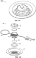
- FIG. 1A shows a top view of an assembled valve 100.
- Valve 100 may comprise various materials.
- valve 100 and/or its components may be constructed from a combination of plastic, polyvinyl chloride ("PVC"), rubber, metal, or any other suitable material or combination of materials to provide the desired qualities described herein.
- PVC polyvinyl chloride
- valve 100 may vary in size and positioning.
- Valve 100 may be positioned on a top surface, a bottom surface, and/or a side surface of an air mattress. It is further contemplated that an air mattress may comprise a plurality of valves 100.
- FIG. 1B illustrates an exploded view of components of a valve 100.
- Valve 100 may include a top cover 105, a top ring 110, a middle valve 115, an adapter ring 120, a default ring 125, a diaphragm 130, a bottom ring 135, and a valve base 140.
- the top cover 105 may include grooves capable of attachment by a screwing motion.
- the top cover 105 may attach to the middle valve 115.
- the top cover 105 may envelop at least portion of the middle valve 115.
- the top cover 105 may attach to the middle valve 115 by other means known in the art.
- the top ring 110 may be inserted between the middle valve 115 and the top cover 105 during attachment.
- the top ring 110 may reduce friction and/or wear of the middle valve 115 and/or the top cover 105.
- the middle valve 115 may be connected to the default ring 125 and/or the adapter ring 120.
- the adapter ring 120 may have grooves allowing attachment to the middle valve 115 through a screwing motion.
- the adapter ring 120 may have a diameter of 18mm.
- the adapter ring 125 may allow the valve 100 to fit an air pump having a nozzle size of 18mm.
- the adapter ring 125 may attach to the middle valve 115 by other means known in the art.
- the default ring 125 and the adapter ring 120 may be connected to the middle valve 115 by the same connection.
- the connection may be flexible such that the adapter ring 120 and/or the default ring 125 are able to bend over a top portion of the middle valve 115.
- the middle valve may have a diameter of 31mm.
- the default ring 125 may also have a diameter of 31mm. Accordingly, the middle valve and/or default ring may allow the valve 100 to fit an air pump having a nozzle size of 31mm.
- a top portion of the diaphragm 130 may enter an opening of a bottom portion of the middle valve 115 such that a connection is created.
- the connection between the diaphragm 130 and the middle valve 115 provides closure of the air valve, which prevents air from entering or exiting the air mattress 400.
- a bottom portion of the diaphragm 130 may positioned within the valve base 140.
- the bottom ring 135 may be positioned between the valve base 140 and the diaphragm 130.
- the bottom ring 135 may reduce friction and/or wear of the middle valve 115 and/or the valve base 140.
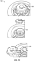
- FIG. 1C illustrates stages of assembly of a valve.
- valve 100 is closed (i.e., the top cover 105 is connected to a top portion of the middle valve 115).
- the top cover 105 is disconnected from a top portion of middle valve 115.
- the middle valve 115 is exposed and therefore, the valve 100 may receive air from an air pump having a diameter of 31mm.
- the top cover 105 is disconnected from a top portion of middle valve 115.
- adapter ring 120 is connected to the middle valve 115. Therefore, the valve 100 may receive air from an air pump having a diameter of 18mm.
- valve 200 may comprise various materials.
- valve 200 and/or its components may be constructed from a combination of plastic, polyvinyl chloride ("PVC"), rubber, metal, or any other suitable material or combination of materials to provide the desired qualities described herein.
- PVC polyvinyl chloride
- valve 200 may vary in size and positioning.
- Valve 200 may be positioned on a top surface, bottom surface, and/or a side surface of an air mattress. It is further contemplated that an air mattress may comprise a plurality of valves 200.
- FIG. 2B illustrates an exploded view of components of valve 200, according to embodiments of the present disclosure.
- Valve 200 may include a top cap 205, a top valve 210, a top ring 215, a middle valve 220, a diaphragm 225, a bottom ring 230, and a valve base 235.
- the top cap 205 may comprise a combination of plastic, polyvinyl chloride ("PVC"), rubber, metal, or any other suitable material or combination of materials.
- PVC polyvinyl chloride
- the top cap 205 may be attachable to the valve base 235, the top valve 210, and/or the middle valve 220.
- the top cap 205 may include one or more circular rings capable of enveloping at least a portion of the middle valve 220, and/or at least a portion of the valve base 235.
- the one or more circular rings of the top cap 205 may be attached to one another at one or more points of attachment.
- the one or more circular rings of the top cap 205 may provide the top cap 205 attachment the middle valve 220 and/or the valve base 235.
- each of the one or more circular rings of the top cap 205 may fit between an attachment of the top valve 210 and the middle valve 220, and/or an attachment of the middle valve 220 and the valve base 235.
- the top cap 205 may include a lid capable of connecting and disconnecting from the body of the top cap 205 such that an opening and closing feature are provided.
- the lid When the lid of the top cap 205 is connected to the body of the top cap 205, the lid may also be connected to the top valve 210.
- the lid of top cap 205 When the lid of top cap 205 is disconnected from the body of top cap 205, an opening is provided such that top valve 210 is exposed.
- Top valve 210 may have a diameter of 18mm. As a result, the valve 200 may receive air from an air pump having a diameter of 18mm.
- the top valve 210 may include an opening at the top portion capable of receiving at least a portion of the top cap 205.
- the top valve 210 may include grooves within an inner portion capable of attaching to another body having similar grooves through a screwing motion.
- the middle valve 220 may screw into the top valve 210 to create attachment.
- the top valve 210 may attach to the middle valve 220 by other means known in the art. As part of attaching to middle valve 220, the top valve 210 may envelop at least a portion of the middle valve 220.
- the top ring 215 may be inserted between the middle valve 220 and the top valve 210 during attachment.
- the top ring 215 may reduce friction and/or wear of the middle valve 220 and/or the top cover 210.
- the middle valve 220 may have a diameter of 31mm.
- the top valve 210 may be disconnected/unattached from the middle valve 220 by an unscrewing motion. When the top valve 210 is unattached from the middle valve 220, an opening is provided such that middle valve 220 is exposed. As a result, the middle valve 220 may allow the valve 200 to fit an air pump having a nozzle size of 18mm.
- a bottom portion of the diaphragm 225 may positioned within the valve base 235.
- the bottom ring 230 may be positioned between the valve base 235 and the diaphragm 225.
- the bottom ring 230 may reduce friction and/or wear of the middle valve 220 and/or the valve base 235.
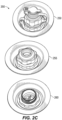
- FIG. 2C illustrates stages of assembly of a valve.
- valve 200 is closed (i.e., the lid of the top cap 205 is connected to the body of top cap 205, and top cap 205 is connected to top valve 210).
- the top cap 205 is disconnected from the top valve 210 and the middle valve 220.
- the top valve 210 may be exposed.
- a top portion of the top valve 210 may include an opening.
- valve 200 may receive air from an air pump having a diameter of 18mm.
- the top valve 210 is disconnected from the middle valve 220.
- a top portion of the middle valve 220 is exposed.
- the top portion of the middle valve 200 may have an opening allowing a flow of air into the valve.
- valve 200 may receive air from an air pump having a diameter of 31mm.
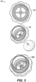
- FIG. 3 illustrates stages of assembly of a middle valve section of a valve.
- the middle valve 220 may be a component of valve 100 and/or valve 200.
- the bottom portion of middle valve 220 can be seen.
- middle valve 220 is unattached from the diaphragm 225.
- This view is consistent with the air mattress 400 being deflated and in a state where the diaphragm 225 does not block air from entering the valve 200.
- the diaphragm 225 is shown with a top most portion facing upwards.
- the middle valve 220 is shown from a top view.
- the middle valve 220 has four cylindrical portions forming a cross shape at a bottom portion.
- the four cylindrical portions attach to an inner portion of the middle valve 220 and form a circular opening toward a middle portion of the inner middle valve 220.
- the top most portion of the diaphragm 225 may have a diameter similar in size to the formed circular opening of middle valve 200 such that the diaphragm 225 may fit into the circular opening.
- the air mattress 400 is in a deflated state such that the diaphragm 225 does not prevent air from entering the valve 200 for inflation.
- the diaphragm 225 is connected to the middle valve 220.
- the air mattress 400 is inflated such that the diaphragm 225 prevents air entering the valve 200.
- FIG. 4 is an overview of an air mattress 400.
- Air mattress 400 may vary in size once inflated based on the desired dimensions and/or number of users.
- air mattress 400 may be a twin, full, queen, or king size bed.
- air mattress 400 may be constructed out of polyvinyl chloride ("PVC"). It is contemplated, however, that other materials such as other plastics or rubber may be used.
- PVC polyvinyl chloride
- the air mattress 400 may comprise a top surface 410 and bottom surface 415 as well as side surfaces (e.g., side surface 420).
- Air mattress 400 may further include valve 100, 200, and/or 300.
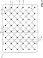
- FIG. 5 is a top view of an embodiment of an air mattress 400 comprising an internal structure 500.
- an internal structure 500 of an air mattress 400 may be included in the interior of the air mattress 400.
- the internal structure 500 may help the air mattress 400 achieve and maintain its intended shape once the air mattress 400 is inflated.
- an internal structure 500 may prevent the air mattress 400 from over-inflating.
- the internal structure 500 may prevent the top surface (e.g., top surface 410) and the bottom surface (e.g., bottom surface 415) from shearing (i.e., moving laterally relative to each other).
- an internal structure 500 may comprise a plurality of connection strips 510 (e.g., strips 510a, 510b) having a predetermined length that are attached (i.e., joined, connected, affixed) to one or more of the top surface 410 and bottom surface 415 of the air mattress 400.
- a connection strip 510 may be constructed from PVC or various other fiber, fabric, or film that is suitable for a particular application.
- a connection strip 510 may be constructed from a single piece of material (e.g., the connection strip 510 may be a single, continuous strip of PVC).
- a connection strip 510 may be constructed from a collection (i.e., a plurality) of materials, fibers, or strings.
- the air mattress 400 can be transparent, thereby providing a view of the plurality of connection strips 510 (e.g., connection strips 510a, 510b) comprising the internal structure 500. Further, the transparency of the air mattress 400 provides a view of top surface connection points 515, as highlighted by dashed box 520, which includes top surface connection point 515a. Further, the transparency of the air mattress 400 provides a view of bottom surface connection points 525, as highlighted by dashed box 530, which includes bottom surface connection point 525a.
- connection points e.g., top surface connection points 515 and bottom surface connection points 525) are on opposing interior surfaces of the top surface 410 and bottom surface 415.
- connection points are on the interior of the air mattress 400.
- connection strips 510 may attach directly to connection points 515 and 525.
- a connection strip 510 may be welded to top and bottom surface attachment points 515, 525.
- a connection strip 510 may be glued, sewn, adhered, or otherwise attached to top and bottom surface attachment points 515, 525.
- a connection strip 510 may attach between a top surface connection point 515 and a bottom surface connection point 525.
- a connection strip 510 may angle from top surface 410 toward bottom surface 415, or vice versa.
- connection strip 510c angles from bottom surface connection point 525b toward top surface connection point 515a.
- connection strip 510d angles from bottom surface connection point 525a toward top surface connection point 515b, according to some embodiments.
- angled connection strips may comprise an internal structure 500 with sufficient strength to prevent the air mattress 400 from over-inflating and to prevent the top surface and bottom surface (e.g., 410 and 415) from moving laterally in relation to one another (i.e., shearing).
- connection strips 510 may connect to a particular top surface connection point 515 or bottom surface connection point 525.
- top surface connection point 515c i.e., top surface connection point 515c
- any number of connection strips 510 could connect to a particular connection point (e.g., a top surface connection point 515 or bottom surface connection point 525. As shown in FIG.
- the plurality of connection strips 510 may constitute an internal structure 500 having a web-like configuration.
- a plurality of top surface connection points 515 may be spaced apart at predetermined distances or intervals, and a plurality of bottom surface connection points may also be spaced apart at predetermined distances or intervals.
- a plurality of bottom surface connection points 525 may be located on the bottom surface 415 in positions that are offset relative to the locations of the plurality of top surface connection points 515 on the top surface 410.
- an internal structure 500 having a web-like configuration may further aid in helping an air mattress 400 maintain its intended shape and prevent the air mattress 400 from becoming over-inflated. Further, an internal structure 500 having a web-like configuration may help prevent the top surface 410 and bottom surface 415 of an air mattress 400 from shearing or moving laterally relative to one another.
- a connection strip 510 may be constructed from a single piece of material. But, in some embodiments, a connection strip 510 may comprise a plurality of individual strips or strands. In some embodiments, each of the plurality of individual strips that comprise a connection strip may attach to the same top surface connection point 515 and bottom surface connection point 525. In some embodiments, however, a connection strip 510 may comprise attachment strips (or, alternatively, weld strips) at each end of the connection strip 510.
- An attachment strip may be a strip of material or a patch, that may be used to affix a portion of an internal structure 500 to a portion of the air mattress 400.
- an attachment strip may be a strip of PVC that may be welded to a surface of the air mattress 400.
- a portion of an internal structure 500 for example, a portion of a connection strip 510, may be sandwiched between an attachment strip and a surface of the air mattress 400 and the attachment strip may be welded to the surface of the air mattress 400 to secure the connection strip 510 to it.
- the plurality of individual strips or strands comprising the connection strip 510 may be held in place by the opposing attachment strips, and the attachment strips may be affixed to the top and bottom surface connection points (i.e., 515 and 525).
- an attachment strip, a portion of a connection strip 510, and a portion of either the top surface 410 or bottom surface 415 may be welded together at a top surface connection point 515 or bottom surface connection point 525.
- FIG. 6 is a perspective view of an air mattress 400 comprising an internal structure 700 that is comprised of a single sheet of material.
- the internal structure 700 may be a continuous piece of material.
- the internal structure may be a mesh structure 610 (which may also be referred to as a "mesh web" or a "mesh sheet") that includes one or more apertures forming a mesh.
- a mesh structure 610 may be made of a single piece of material including a plurality of apertures.
- an internal structure 600 of an air mattress 400 may be included in the interior of the air mattress 400 and may operate in a manner similar to internal structure 500 described above.
- the internal structure 600 may help the air mattress 400 achieve and maintain its intended shape once the air mattress 400 is inflated. Further, internal structure 600 may prevent the air mattress from over-inflating. Similarly, the internal mesh structure 600 may prevent the top surface (e.g., top surface 410) and the bottom surface (e.g., bottom surface 415) from shearing (i.e., moving laterally relative to each other). In some embodiments, the outer edge of the internal structure 600 may be attached to the inner surfaces of the side surfaces 420.
- a mesh structure 610 may be constructed from PVC or various other fiber, fabric, or film that is suitable for a particular application. In some embodiments, a mesh structure 610 may be constructed form a single piece of material (e.g., the mesh structure 610 may be a single, continuous piece of fiber). In some embodiments, a mesh structure 610 may be constructed from a collection (i.e., plurality) of materials, fibers, or strings.
- a mesh structure 610 may attach to the internal surface of an air mattress 400 at various top surface connection points 615 and bottom surface connection points 625.
- the top surface connection points 615 and bottom surface connection points 625 may be located in positions similar to those shown with respect to internal structure 500 and creating a 3D web-like structure as previously described above.
- a plurality of top surface connection points 615 may be spaced apart at predetermined distances or intervals, and a plurality of bottom surface connection points may also be spaced apart at predetermined distances or intervals.
- a plurality of bottom surface connection points 625 may be located on the bottom surface 415 in positions that are offset relative to the locations of the plurality of top surface connection points 615 on the top surface 410.
- the mesh structure 610 when air mattress 400 is inflated, the mesh structure 610 may take on a 3-dimensional, approximately sinusoidal shape with top and bottom "humps" extending in upwards and/or downwards directions when the airbed is inflated, as shown in FIG. 6 .
- the peak of each top hump may attach to the air mattress 400 at a top connection point 615 and the trough of each bottom hump may attach to the air mattress 400 at a bottom connection point 625.
- an internal structure 600 having a web-like configuration may help prevent the top surface 410 and bottom surface 415 of an air mattress 400 from shearing and moving laterally relative to one another.
- a mesh structure 610 may attach (i.e., join, connect, affix) to the top surface 410 and bottom surface 415 of the air mattress 400.
- a mesh structure 610 may attach to the air mattress 400 at one or more top surface connection points 615 and one or more bottom surface connection points 625.
- portions of a mesh structure 610 may be welded to top and bottom surface attachment points 615, 625.
- portions of the mesh structure 610 may be attached to the air mattress 400 with one or more attachment strips.
- an attachment strip may be used to secure a portion of a mesh structure 610 to a top surface connection point 615 or a bottom surface connection point 625.
- portions of the mesh structure 610 may be attached to the air mattress 400 with one or more attachment strips.
- a top connection point 615 may be sandwiched between an attachment strip and the top surface 410 and the three may be welded together.
- a bottom surface connection point 625 may be sandwiched between an attachment strip and the bottom surface 415 and the three may be welded together.
- an attachment strip may be a PVC strip.
- a mesh structure 610 may be glued, sewn, adhered, or otherwise attached to top and bottom surface attachment points 615, 625.
- FIG. 7 is an embodiment of an air mattress 400 comprising a top surface 410, bottom surface 415, a plurality of side surfaces (e.g., side surface 420), and various air mattress 400 components.
- an air mattress 400 may comprise a portable power source 710.
- a portable power source 710 may be a battery and provide direct current.
- portable power source 710 may include a motor or generator and provide alternating current. It is contemplated that any portable power source may be used.
- a portable power source 710 may be housed in a power source housing (not shown) on air mattress 400 for convenient transport.
- a portable power source 710 may comprise a power plug 715, which may be attachable to portable power source 710. In some embodiments, however, power plug 715 may be used in lieu of portable power source 710. Power plug 715 may include a variety of power plugs, such as those configured to plug into USB ports and 120V standard outlets. As will be appreciated, while a portable power source 710 may be used in outdoor and indoor locations, a power plug 715 may be suited for indoor use when air mattress 100 is placed near an electrical outlet.
- an air mattress may comprise an air control system 720, which may be used to control air flow and to inflate and deflate an air mattress 400.
- a portable power source 710 or a power plug 715 (or a combination of both) may provide power to an air control system 720.
- an air control system 720 may include an air intake component 722 and a controller 724.
- An air intake component 722 may be configured to direct ambient air into the air mattress 400 during mattress inflation and direct air from the air mattress 400 during mattress deflation.
- the air intake component 722 may comprise an outer seal that inhibits or allows the flow of outside air into the air control system 720.
- the air intake component 722 also may include an inner seal (not shown) that inhibits or allows the flow of internal air between air control system 720 and the air chamber (i.e., interior) of an air mattress 400.
- a controller 724 may be configured to receive user input and control the opening or closing of inner and outer seals and/or inflating and deflating of the air mattress 400 via the air control system 720.
- the controller 724 may include one or more processors having memory.
- the controller 724 may be configured to execute one or more operating modes. For example, operating modes may include inflation mode, deflation mode, air recirculation mode, and standby mode.
- the controller 724 may include one or more electronic components that allow a user to switch between modes.
- inflation mode may begin when the controller 724 receives user input to inflate the air mattress 400. In some embodiments, inflation mode may last until the controller 724 receives additional user input to stop inflating the air mattress 400. In some embodiments, however, the controller 724 may automatically control the speed and duration of inflation based on a predetermined or user supplied air pressure for the air in the air mattress 400. During inflation mode, both the inner and outer seals may be open to allow ambient air to flow into the air mattress 400.
- deflation mode may begin when the controller 724 receives user input to deflate the air mattress 400. For example, in some embodiments, deflation mode may last until the controller 724 receives additional user input to stop deflating the air mattress 400. Further, in some embodiments, the controller 724 may automatically control the speed and duration of deflation based on a predetermined or user supplied air pressure for the air in the air mattress 400. During deflation mode, both the inner and outer seals may be open to allow ambient air to flow out of the air mattress 400.
- an air recirculation mode may begin when the controller 724 receives user input to circulate air within air mattress 100. In doing so, the controller 724 may direct the outer seal to close while the inner seal remains open, thus allowing air to enter the air intake component 722, but not escape the air mattress 400. According to some embodiments, circulating air within an air mattress 400 may cause a vibrating or massaging pulse on the surface of the air mattress 400 and/or adjust air pressure via air control system 720. In some embodiments, air recirculation mode may last until the controller 724 receives additional user input to stop circulating air within the air mattress 400. Also, in some embodiments, the controller 724 may automatically control the time duration and/or interval to recirculate air within the air mattress 400.
- a standby mode may occur when the controller 724 receives power from portable power source 710 and/or power plug 715 and is not placed in another mode.
- the controller 724 may operate in standby mode before receiving user input.
- the controller 724 may also direct the inner seal to close to inhibit air recirculation.
- the controller 724 may direct the inner seal to remain open. It is contemplated that the air mattress 400 may only include the outer seal and not the inner seal, according to some embodiments.
- an air mattress 400 may comprise valve 100, 200, and/or 300. As shown, air mattress 400 may comprise valve 100. According to some embodiments, valve 100 may be configured to inhibit the flow of air out of the air mattress 400 when valve 100 is in a closed position and allow air flow out of air mattress 400 when 100 is in an open position.
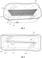
- FIGs. 8-11 depict an air cushion representative of an air mattress, in accordance with some embodiments of the disclosed technology.
- the air cushion depicted includes a single internal support structure 810, which includes a first side strip 816 positioned outside the loop 812 and proximate the overlapping ends and a second side strip 816 a second side strip 816 may be positioned outside the loop 812 and adjacent a portion of the loop 812 opposite the overlapping ends of the loop 812, as discussed above.
- attachment of the first side strip 816 to the second side strip 816 causes the loop 812 to "pinch" together at or near the first and second side strips 816.
- a single support structure 1010 is shown, it is understood that a plurality of similar support structures could be used in an air mattress, according to the disclosed technology.
Landscapes
- Engineering & Computer Science (AREA)
- General Engineering & Computer Science (AREA)
- Mechanical Engineering (AREA)
- Mattresses And Other Support Structures For Chairs And Beds (AREA)
Applications Claiming Priority (3)
| Application Number | Priority Date | Filing Date | Title |
|---|---|---|---|
| CN201920129792.0U CN210043597U (zh) | 2019-01-25 | 2019-01-25 | 充气床垫装置 |
| EP20745881.1A EP3914841B1 (de) | 2019-01-25 | 2020-01-25 | Verbessertes luftbettventil |
| PCT/US2020/015123 WO2020154711A1 (en) | 2019-01-25 | 2020-01-25 | Improved air bed valve |
Related Parent Applications (2)
| Application Number | Title | Priority Date | Filing Date |
|---|---|---|---|
| EP20745881.1A Division EP3914841B1 (de) | 2019-01-25 | 2020-01-25 | Verbessertes luftbettventil |
| EP20745881.1A Division-Into EP3914841B1 (de) | 2019-01-25 | 2020-01-25 | Verbessertes luftbettventil |
Publications (3)
| Publication Number | Publication Date |
|---|---|
| EP4521006A2 true EP4521006A2 (de) | 2025-03-12 |
| EP4521006A3 EP4521006A3 (de) | 2025-05-14 |
| EP4521006B1 EP4521006B1 (de) | 2026-01-21 |
Family
ID=69376345
Family Applications (2)
| Application Number | Title | Priority Date | Filing Date |
|---|---|---|---|
| EP20745881.1A Active EP3914841B1 (de) | 2019-01-25 | 2020-01-25 | Verbessertes luftbettventil |
| EP25151215.8A Active EP4521006B1 (de) | 2019-01-25 | 2020-01-25 | Verbessertes luftbettventil |
Family Applications Before (1)
| Application Number | Title | Priority Date | Filing Date |
|---|---|---|---|
| EP20745881.1A Active EP3914841B1 (de) | 2019-01-25 | 2020-01-25 | Verbessertes luftbettventil |
Country Status (5)
| Country | Link |
|---|---|
| US (1) | US12440040B2 (de) |
| EP (2) | EP3914841B1 (de) |
| CN (3) | CN210043597U (de) |
| CA (1) | CA3127929A1 (de) |
| WO (1) | WO2020154711A1 (de) |
Cited By (1)
| Publication number | Priority date | Publication date | Assignee | Title |
|---|---|---|---|---|
| US20250031863A1 (en) * | 2019-06-12 | 2025-01-30 | Belgravia Wood Limited | Air bed having an improved built-in air pump |
Families Citing this family (11)
| Publication number | Priority date | Publication date | Assignee | Title |
|---|---|---|---|---|
| US12279700B2 (en) * | 2018-12-18 | 2025-04-22 | Belgravia Wood Limited | Internal support system for an inflatable air mattress |
| GB2614132B (en) * | 2020-06-04 | 2025-11-12 | Spin Master Inc | Inflatable object and valve therefor |
| USD1069986S1 (en) | 2021-06-09 | 2025-04-08 | Spin Master, Inc. | Valve |
| USD1039113S1 (en) | 2021-06-09 | 2024-08-13 | Spin Master, Inc. | Valve |
| USD1018782S1 (en) * | 2021-09-23 | 2024-03-19 | Shenzhen Jiaxin Technology Co., Ltd. | Drain valve |
| USD970691S1 (en) * | 2022-01-04 | 2022-11-22 | Shenzhen Jiaxin Technology Co., Ltd. | Rapid valve |
| US20230213106A1 (en) * | 2022-01-05 | 2023-07-06 | Belgravia Wood Limited | Air valve, inflation, and deflation apparatuses and methods |
| USD1108252S1 (en) * | 2022-05-03 | 2026-01-06 | Alessandro ADDIS | Plug for deflating air beds |
| US20250107637A1 (en) * | 2023-10-02 | 2025-04-03 | Comfetravel LLC | Portable inflatable mattress |
| TR2023014424A1 (tr) * | 2023-11-06 | 2025-05-21 | Retay Silah Otomotiv Insaat Ve Gida Sanayi Ve Ticaret Ltd Sirketi | Tüfekler i̇çi̇n omuzluk yapilanmasi |
| USD1053309S1 (en) * | 2024-08-14 | 2024-12-03 | Yue Zhang | Water valve |
Family Cites Families (20)
| Publication number | Priority date | Publication date | Assignee | Title |
|---|---|---|---|---|
| US4141770A (en) * | 1977-05-16 | 1979-02-27 | Mollura Carlos A | Method of making a baffled waterbed |
| US4328599A (en) * | 1979-06-27 | 1982-05-11 | Mollura Carlos A | Firmness regulated waterbed mattress |
| GB2208353B (en) * | 1987-08-07 | 1990-10-31 | Hubert Bryan Jervis | Air nozzle adaptor |
| US5941272A (en) * | 1996-12-04 | 1999-08-24 | Imaginair, Inc. | Three way universal valve |
| WO2002018825A1 (en) * | 2000-08-30 | 2002-03-07 | Sunco Products, Inc. | Multi-configurable valve system |
| US6648004B2 (en) * | 2001-02-15 | 2003-11-18 | Pleasure Time Products (Hong Kong) Limited | Air valve for inflatable article |
| CN2632437Y (zh) | 2003-07-17 | 2004-08-11 | 明达塑胶(厦门)有限公司 | 充放气阀 |
| US7191481B2 (en) | 2004-12-22 | 2007-03-20 | Hao Hsu | Airbed |
| CN2814060Y (zh) * | 2005-06-06 | 2006-09-06 | 巫新财 | 一种充气品的充气风嘴 |
| US20070074760A1 (en) * | 2005-08-15 | 2007-04-05 | Hsin-Tsai Wu | Inflatable device |
| US20090070941A1 (en) * | 2007-09-18 | 2009-03-19 | Lau Vincent W S | Inflatable bed assembly |
| US20090320211A1 (en) * | 2007-10-16 | 2009-12-31 | Lau Vincent W S | Inflatable bed with cushion cells |
| US7694372B1 (en) | 2009-04-07 | 2010-04-13 | Dennis Boyd | Air mattress |
| CN201757202U (zh) * | 2010-08-30 | 2011-03-09 | 宋荣治 | 泄压阀 |
| US8584695B2 (en) * | 2010-10-15 | 2013-11-19 | Ideal Time Consultants Limited | Air valve for inflatable device |
| WO2015051394A1 (en) * | 2013-10-08 | 2015-04-16 | Sea To Summit Pty Ltd | Improved valve for inflatable devices |
| US20160186874A1 (en) * | 2014-12-31 | 2016-06-30 | Feng Yi Outdoor Leisure Equipment Enterprise Co., Ltd. | Air Valve Structure for Inflatable Air Cushion |
| US10327563B2 (en) * | 2015-05-11 | 2019-06-25 | Polygroup Macau Limited (Bvi) | Systems and methods for internal airbed structure |
| CN110546417B (zh) | 2017-05-04 | 2022-01-18 | 上海荣威塑胶工业有限公司 | 3合1空气阀组件 |
| CN209807775U (zh) | 2018-12-18 | 2019-12-20 | 贝尔格莱维亚伍德有限公司 | 可充气气垫 |
-
2019
- 2019-01-25 CN CN201920129792.0U patent/CN210043597U/zh active Active
-
2020
- 2020-01-25 WO PCT/US2020/015123 patent/WO2020154711A1/en not_active Ceased
- 2020-01-25 CN CN202080018516.2A patent/CN113597525B/zh active Active
- 2020-01-25 EP EP20745881.1A patent/EP3914841B1/de active Active
- 2020-01-25 EP EP25151215.8A patent/EP4521006B1/de active Active
- 2020-01-25 US US17/425,855 patent/US12440040B2/en active Active
- 2020-01-25 CN CN202411951489.0A patent/CN119467791A/zh active Pending
- 2020-01-25 CA CA3127929A patent/CA3127929A1/en active Pending
Cited By (1)
| Publication number | Priority date | Publication date | Assignee | Title |
|---|---|---|---|---|
| US20250031863A1 (en) * | 2019-06-12 | 2025-01-30 | Belgravia Wood Limited | Air bed having an improved built-in air pump |
Also Published As
| Publication number | Publication date |
|---|---|
| CN113597525A (zh) | 2021-11-02 |
| CA3127929A1 (en) | 2020-07-30 |
| US12440040B2 (en) | 2025-10-14 |
| EP4521006B1 (de) | 2026-01-21 |
| CN113597525B (zh) | 2025-01-17 |
| EP3914841A4 (de) | 2022-10-12 |
| CN210043597U (zh) | 2020-02-11 |
| EP4521006A3 (de) | 2025-05-14 |
| EP3914841A1 (de) | 2021-12-01 |
| US20220125213A1 (en) | 2022-04-28 |
| CN119467791A (zh) | 2025-02-18 |
| EP3914841B1 (de) | 2025-02-26 |
| WO2020154711A1 (en) | 2020-07-30 |
Similar Documents
| Publication | Publication Date | Title |
|---|---|---|
| EP4521006B1 (de) | Verbessertes luftbettventil | |
| US12114783B2 (en) | Air bed having an improved built-in air pump | |
| US10455949B2 (en) | Systems and methods for internal airbed structure | |
| JP3419774B2 (ja) | 空気支持システム | |
| US20260026633A1 (en) | Air bed valve | |
| EP0487641A1 (de) | Faltbares luftbett. | |
| US11330914B2 (en) | Internal support system for an inflatable air mattress | |
| CN100486486C (zh) | 包括覆盖层和锚固装置的充气装置 | |
| WO2018145763A1 (en) | Housing for holding an air pump, an air pump, and an inflatable device | |
| AU2022204908B2 (en) | Systems and methods for internal airbed structure | |
| CN211501196U (zh) | 一种气垫桌/椅的连接结构及气垫桌/椅 |
Legal Events
| Date | Code | Title | Description |
|---|---|---|---|
| PUAI | Public reference made under article 153(3) epc to a published international application that has entered the european phase |
Free format text: ORIGINAL CODE: 0009012 |
|
| STAA | Information on the status of an ep patent application or granted ep patent |
Free format text: STATUS: THE APPLICATION HAS BEEN PUBLISHED |
|
| AC | Divisional application: reference to earlier application |
Ref document number: 3914841 Country of ref document: EP Kind code of ref document: P |
|
| AK | Designated contracting states |
Kind code of ref document: A2 Designated state(s): AL AT BE BG CH CY CZ DE DK EE ES FI FR GB GR HR HU IE IS IT LI LT LU LV MC MK MT NL NO PL PT RO RS SE SI SK SM TR |
|
| REG | Reference to a national code |
Ref country code: DE Ref country code: DE Ref legal event code: R079 Ref document number: 602020065744 Country of ref document: DE Free format text: PREVIOUS MAIN CLASS: F16K0024060000 Ipc: F16K0015200000 |
|
| PUAL | Search report despatched |
Free format text: ORIGINAL CODE: 0009013 |
|
| AK | Designated contracting states |
Kind code of ref document: A3 Designated state(s): AL AT BE BG CH CY CZ DE DK EE ES FI FR GB GR HR HU IE IS IT LI LT LU LV MC MK MT NL NO PL PT RO RS SE SI SK SM TR |
|
| RIC1 | Information provided on ipc code assigned before grant |
Ipc: F16K 24/06 20060101ALI20250404BHEP Ipc: B60C 29/06 20060101ALI20250404BHEP Ipc: B60C 29/00 20060101ALI20250404BHEP Ipc: A47C 27/08 20060101ALI20250404BHEP Ipc: F16K 15/20 20060101AFI20250404BHEP |
|
| STAA | Information on the status of an ep patent application or granted ep patent |
Free format text: STATUS: REQUEST FOR EXAMINATION WAS MADE |
|
| GRAP | Despatch of communication of intention to grant a patent |
Free format text: ORIGINAL CODE: EPIDOSNIGR1 |
|
| STAA | Information on the status of an ep patent application or granted ep patent |
Free format text: STATUS: GRANT OF PATENT IS INTENDED |
|
| 17P | Request for examination filed |
Effective date: 20250523 |
|
| INTG | Intention to grant announced |
Effective date: 20250624 |
|
| GRAS | Grant fee paid |
Free format text: ORIGINAL CODE: EPIDOSNIGR3 |
|
| GRAA | (expected) grant |
Free format text: ORIGINAL CODE: 0009210 |
|
| STAA | Information on the status of an ep patent application or granted ep patent |
Free format text: STATUS: THE PATENT HAS BEEN GRANTED |
|
| AC | Divisional application: reference to earlier application |
Ref document number: 3914841 Country of ref document: EP Kind code of ref document: P |
|
| AK | Designated contracting states |
Kind code of ref document: B1 Designated state(s): AL AT BE BG CH CY CZ DE DK EE ES FI FR GB GR HR HU IE IS IT LI LT LU LV MC MK MT NL NO PL PT RO RS SE SI SK SM TR |
|
| REG | Reference to a national code |
Ref country code: CH Ref legal event code: F10 Free format text: ST27 STATUS EVENT CODE: U-0-0-F10-F00 (AS PROVIDED BY THE NATIONAL OFFICE) Effective date: 20260121 |
|
| REG | Reference to a national code |
Ref country code: DE Ref legal event code: R096 Ref document number: 602020065744 Country of ref document: DE |
|
| P01 | Opt-out of the competence of the unified patent court (upc) registered |
Free format text: CASE NUMBER: UPC_APP_0001581_4521006/2026 Effective date: 20260116 |
|
| REG | Reference to a national code |
Ref country code: IE Ref legal event code: FG4D |