EP4521032A1 - Klimaanlage mit konfiguration zur anordnung in einem innenraum - Google Patents
Klimaanlage mit konfiguration zur anordnung in einem innenraum Download PDFInfo
- Publication number
- EP4521032A1 EP4521032A1 EP23195998.2A EP23195998A EP4521032A1 EP 4521032 A1 EP4521032 A1 EP 4521032A1 EP 23195998 A EP23195998 A EP 23195998A EP 4521032 A1 EP4521032 A1 EP 4521032A1
- Authority
- EP
- European Patent Office
- Prior art keywords
- air
- air path
- air conditioner
- indoor space
- path
- Prior art date
- Legal status (The legal status is an assumption and is not a legal conclusion. Google has not performed a legal analysis and makes no representation as to the accuracy of the status listed.)
- Pending
Links
Images



Classifications
-
- F—MECHANICAL ENGINEERING; LIGHTING; HEATING; WEAPONS; BLASTING
- F24—HEATING; RANGES; VENTILATING
- F24F—AIR-CONDITIONING; AIR-HUMIDIFICATION; VENTILATION; USE OF AIR CURRENTS FOR SCREENING
- F24F1/00—Room units for air-conditioning, e.g. separate or self-contained units or units receiving primary air from a central station
- F24F1/02—Self-contained room units for air-conditioning, i.e. with all apparatus for treatment installed in a common casing
- F24F1/022—Self-contained room units for air-conditioning, i.e. with all apparatus for treatment installed in a common casing comprising a compressor cycle
-
- F—MECHANICAL ENGINEERING; LIGHTING; HEATING; WEAPONS; BLASTING
- F24—HEATING; RANGES; VENTILATING
- F24F—AIR-CONDITIONING; AIR-HUMIDIFICATION; VENTILATION; USE OF AIR CURRENTS FOR SCREENING
- F24F12/00—Use of energy recovery systems in air conditioning, ventilation or screening
- F24F12/001—Use of energy recovery systems in air conditioning, ventilation or screening with heat-exchange between supplied and exhausted air
- F24F12/002—Use of energy recovery systems in air conditioning, ventilation or screening with heat-exchange between supplied and exhausted air using an intermediate heat-transfer fluid
- F24F12/003—Use of energy recovery systems in air conditioning, ventilation or screening with heat-exchange between supplied and exhausted air using an intermediate heat-transfer fluid using a heat pump
-
- F—MECHANICAL ENGINEERING; LIGHTING; HEATING; WEAPONS; BLASTING
- F24—HEATING; RANGES; VENTILATING
- F24F—AIR-CONDITIONING; AIR-HUMIDIFICATION; VENTILATION; USE OF AIR CURRENTS FOR SCREENING
- F24F5/00—Air-conditioning systems or apparatus not covered by F24F1/00 or F24F3/00, e.g. using solar heat or combined with household units such as an oven or water heater
- F24F5/0046—Air-conditioning systems or apparatus not covered by F24F1/00 or F24F3/00, e.g. using solar heat or combined with household units such as an oven or water heater using natural energy, e.g. solar energy, energy from the ground
-
- F—MECHANICAL ENGINEERING; LIGHTING; HEATING; WEAPONS; BLASTING
- F24—HEATING; RANGES; VENTILATING
- F24F—AIR-CONDITIONING; AIR-HUMIDIFICATION; VENTILATION; USE OF AIR CURRENTS FOR SCREENING
- F24F7/00—Ventilation
- F24F7/04—Ventilation with ducting systems, e.g. by double walls; with natural circulation
- F24F7/06—Ventilation with ducting systems, e.g. by double walls; with natural circulation with forced air circulation, e.g. by fan positioning of a ventilator in or against a conduit
- F24F7/08—Ventilation with ducting systems, e.g. by double walls; with natural circulation with forced air circulation, e.g. by fan positioning of a ventilator in or against a conduit with separate ducts for supplied and exhausted air with provisions for reversal of the input and output systems
Definitions
- the present disclosure concerns an air conditioner which is configured to be located in an indoor space.
- the disclosed air conditioner may for example relate to a portable air conditioner, or a monoblock.
- an air conditioner may be located entirely in an indoor space. Such an air conditioner may be necessary so that external equipment is not required to be installed outside, such as externally on a building, which may be detrimental to the facade. Additionally, an air conditioner may be desired having portability, such that it may be easily removed, or moved to another location.
- Such an air conditioner comprises a compressor and refrigerant loop which may cool an air supply, and an interface with the indoor space for the supply of cool air, and an interface with the outdoor space for the removal of air from the indoor space such that heat may be removed from the refrigerant loop.
- a primary objective of the present disclosure is to achieve, in at least some aspect, an improved air conditioner.
- it is an objective to achieve an air conditioner whereby cooling of an indoor space can be achieved in an energy efficient manner and/or in a relatively quiet manner.
- an air conditioner configured to be located in an indoor space, the air conditioner comprising:
- the indoor space may comprise a building, a room of a building, or may comprise a temporary space which at least partially delimits a volume from its surroundings.
- the outdoor space may comprise a space outside the building, the room of the building, etc., for example the outdoor space may comprise a space inside a building but outside of the indoor space.
- the air conditioner being configured to be located in the indoor space means that no external unit, located in the outdoor space, is necessary for it to function.
- the first air path, the second air path, and the third air path may comprise tubes, pipes, or the like.
- the air paths may comprise surfaces such as wall members, shell members, and the like, as long as a pathway is at least partially delimited such that air can flow from the inlet to the outlet.
- the inlet portions extend from the air path inlets and the outlet portions extend from the air path outlets; the inlet portions may meet the outlet portions, alternatively a portion may be formed therebetween.
- the portions may be continuously formed as a single part, or alternatively may be formed of multiple parts, and/or may comprise a portion of a part.
- the terms inlet and outlet refer to the normal use of the air conditioner, it may further be possible for the device to operate in modes such that the inlets comprise outlets and vice-versa.
- the air supply system and air removal system may comprise a fan, such as an axial fan, a radial fan, or any type of fan. Additionally, the air supply system and air removal system may comprise any number of fans.
- the third air path being distinct from the first air path and the second air path means that the third air path is physically separate from the first air path and the second air path, i.e., the air paths do not overlap.
- the walls delimiting the air paths may be physically separate, and/or a gap may be formed between the air paths, the space comprising a void, insulation, or further components of the air conditioner.
- an air conditioner having three air paths, and wherein the third air path is distinct from the first air path and the second air path, it is possible to supply air to the indoor space via the first air path or the second air path, whereby the air does not mix with the air in the third air path.
- heat exchange can be minimized, and thus a supplied air can be provided, either by cooling via the refrigerant loop, or from outside as a ventilation air, and a more effective cooling is thereby achieved.
- the supplied air does not come in contact with any components having been warmed by air which has previously been in contact.
- the air conditioner according to the disclosure may additionally or alternatively improve the accuracy of any measurements of the air in the air paths, such as temperature measurements since the air in the first and second air paths do not mix with the air in the third air path. Improved accuracy of e.g., the temperature measurements may result in improved air conditioner efficiency.
- the air conditioner is configured to cool the indoor space by supplying air to the indoor space via the first air path when a temperature of the outdoor space is less than a temperature of the indoor space, and by supplying cooled air to the indoor space via the second air path when a temperature of the outdoor space is not less than a temperature of the indoor space.
- the indoor space via the first air path when a temperature of the outdoor space is less than a temperature of the indoor space, it is possible to cool the indoor space without use of the refrigerant loop, and therefore without the need for powering the compressor. Thereby, energy efficiency may be improved and any disturbing noise from the compressor can be avoided.
- By cooling the indoor space via the second air path when a temperature of the outdoor space is not less than a temperature of the indoor space it is possible to cool the indoor space to temperatures below the temperature of the air in the outdoor space.
- the air conditioner further comprises at least one closing element, configured to be movable between a first position and a second position, wherein at the first position the at least one closing element closes the first air path and at the second position the at least one closing element opens the first air path.
- at the first position the at least one closing element closes the first air path and at the second position the at least one closing element opens the first air path.
- the at least one closing element is further configured to close the second air path at the second position and open the second air path at the first position.
- a closing element configured to close the second air path it is possible to prevent air from being circulated in the indoor space via the second air path.
- at least one closing element configured to close the first air path
- at least one closing element configured to close the second air path it is possible to close one of the first air path and the second air path whilst the other is open, thus it may be possible to use a single fan to supply air to the indoor space via either the first air path or the second air path.
- the at least one closing element for the first air path may be the same closing element(s) used for the second air path, instead of e.g., using separate closing elements for each air path. Thereby, a more cost-effective configuration may be achieved.
- the air conditioner comprises a first closing element and a second closing element, wherein at the first position the first closing element and the second closing element connect with one another, and at the second position a gap is formed between the first closing element and the second closing element, whereby optionally the first and second closing elements are arranged to be movable back and forth by a sliding motion between the first and second positions.
- Connecting with one another can refer to the first closing element and the second closing element contacting one another, or alternatively being connected via an element which the two closing elements mutually contact.
- the first air path outlet portion and the second air path outlet portion at least partially overlap.
- overlapping the first air path outlet portion and the second air path outlet portion it is possible to provide a single outlet for the two air paths, thus providing a more compact air conditioner.
- the air conditioner may be simplified as a only single set of vanes, or the like, are required to affect the air supply from the two air paths.
- An overlap in air paths may also allow for a residual cooling of air which is supplied from the outside space following cooling using the refrigerant loop.
- the first air path inlet portion is distinct from the second air path.
- the air in the first air path inlet does not mix with the air in the second air path. If for example a temperature sensor is present in the first air path inlet portion having the first inlet portion distinct from the second air path, more accurate measurements may be produced.
- the first air path inlet portion at least partially comprises a first tube.
- the tube may comprise a flexible tube.
- the third air path outlet portion at least partially comprises a second tube.
- the tube may comprise a flexible tube.
- the first temperature sensor is located in the first air path inlet portion.
- the temperature sensor may detect the temperature of the air from the outside space which is to be supplied to the indoor space.
- the air conditioner comprises at least one closing element configured to close the first air path, positioning the first temperature sensor closer to the first air path inlet than the at least one closing element may allow for measurements to be taken indicative of the temperature of the air outside without opening the at least one closing element.
- the first temperature sensor is configured to measure a temperature of the air in the outdoor space when air is supplied to the indoor space via the first air path.
- Supply of air via the first air path may comprise opening of a closing element, and/or activation of a fan of the air supply system, where applicable.
- opening of the closing element may be a necessity for the outdoor space air temperature to be measured.
- the first temperature sensor is configured to measure a temperature of the air in the outdoor space at predetermined intervals when the air conditioner is configured to cool the indoor space.
- Predetermined intervals may comprise regular intervals, such as every 10 minutes, half an hour, every hour, etc.
- the intervals may be irregular, for example the intervals could be dependent on the last measured temperature, a predicted temperature, time of day, or a temperature of the air in the indoor space, etc.
- the air conditioner further comprises a second temperature sensor configured to measure a temperature of the air in the indoor space.
- the second temperature sensor may be located in the first air path inlet portion, wherein the sensor may be suspended in the air path or may be in contact with a wall of the air path.
- the second temperature sensor may be located on an external surface of the air conditioner.
- the temperature sensor may directly measure the air temperature, alternatively the temperature sensor may measure a material in thermal contact with the air such that a measurement indicative of the air temperature may be obtained.
- the air conditioner is a portable unit and/or a wall mounted unit.
- a portable unit may comprise a unit having wheels, a handle, or any adaptations such that it may be more easily moved.
- a wall mounted unit may comprise any type of air conditioning unit configured to be located entirely within an indoor space which is to be mounted onto a surface of the indoor space, such as a wall, ceiling, floor, either directly mounted, or mounted via a bracket.
- Fig. 1 is a perspective view of an air conditioner 2 according to a first embodiment of the disclosure.
- the air conditioner 2 is located in an indoor space 4.
- the indoor space 4 may comprise a building, a room of a building, or may comprise a temporary space which at least partially delimits a volume from its surroundings.
- the indoor space 4 comprises a wall 5 having a window 7, the wall 5 acting as a boundary between the indoor space 4 and an outdoor space 10.
- the air conditioner 2 comprises a main body 3.
- the main body 3 comprises a second air path inlet 48 (not shown), a cooling air outlet 44, and an air removal inlet 46 interfacing with the indoor space 4.
- the inlets and outlets interfacing with the indoor space 4 may comprise vanes, or the like to direct the flow.
- cooling air outlet 44 may comprise vanes, or the like, which create turbulent flow in the indoor space 4, which may improve cooling.
- the second air path inlet 48 and/or the air removal inlet 46 may comprise, vanes, or the like, which create turbulent flow, which may improve heat exchange.
- any vanes, or the like may be adjustable, either manually or automatically such that the direction of the flow may be adjusted.
- inlets interfacing with the indoor space 4 may comprise filters, such that particulate matter may be prevented from entering into the main body 3 of the air conditioner 2, and the air supplied to the indoor space 4 may be cleaned.
- the air conditioner 2 further comprises a first tube 40 and a second tube 42 (described in more detail with reference to Fig. 2 ) extending from the main body 3, which interface with an outdoor space 10.
- the outdoor space 10 may comprise a space outside the building, the room of the building, etc., for example the outdoor space may comprise a space inside a building but outside of the indoor space 4.
- the air conditioner 2 does not need to comprise a first tube 40 and a second tube 42, in alternative embodiments the main body 3 may be positioned at the wall 5 and an interface formed between the main body 3 and the outdoor space 10, for example the air conditioner may comprise a monoblock.
- tubes may be supplied external to the air conditioner 2 which are connected to the device. Such tubes may comprise an installation in a building or may be a peripheral element. Furthermore, the first tube 40 and the second tube 42 interface with the outdoor space 10 via the window 7. It is also possible for the first tube 40 and/or the second tube 42 to interface with the outdoor space 10 via a hole in the wall 5, or a plurality of holes in the wall 5. Additionally, it may be possible for the first tube 40 and/or the second tube 42 to interface with the outdoor space 10 via a roof, or floor, or any gap formed in a wall delimiting the indoor space. Adapters and/or sealing elements may be used to fix the tubes to the window and/or hole, etc. An outdoor air inlet 50 is formed at the interface between the first tube 40 and the outdoor space 10, and an outdoor air outlet 52 is formed at the interface between the second tube 42 and the outdoor space 10.
- the main body 3 additionally comprises a first tube opening 54 and a second tube opening 56 (see Fig. 2 ).
- the first tube opening 50 and the second tube opening 52 provide an interface between the first tube 40 and the second tube 42 and the main body 3 of the air conditioner 2.
- the tubes and/or openings may comprise threads, grooves, protrusions, etc., such that they may be fixed together. Additionally, adapters and/or sealing elements may be used to fix the tubes to the main body 3 of the air conditioner 2.
- the air conditioner 2 comprises a portable unit having wheels 58, although it is not necessary for the air conditioner 2 to have wheels. It may be useful for the air conditioner 2 to comprise a handle such that it may be more easily moved. Such a portable unit may be moved within a room, or to another room, or to another building, and/or the first tube 40 and the second tube 42 may be positioned to form a new interface with the outdoor space 10.
- the air conditioner 2 may also comprise a wall mounted unit.
- a wall mounted unit may be mounted anywhere on the wall 5 from the ceiling to the floor. Additionally, it may be possible to mount the wall mounted unit to the ceiling, or to the floor.
- the wall mounted unit may be mounted directly to a wall, using any known fixation means or may be mounted via a bracket, or the like. It is also possible that the portable unit may be secured to a surface of the indoor space 4.
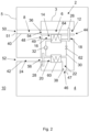
- Fig. 2 is a schematic diagram of the air conditioner 2 of Fig. 1 .
- the air conditioner 2 comprises a first air path 6, a second air path 14, and a third air path 20.
- the first air path 6 comprises a first air path inlet portion 8 and a first air path outlet portion 12.
- the first air path inlet portion 8 interfaces with the outdoor space 10 at the outdoor air inlet 50, and the first air path outlet 12 portion interfaces with the indoor space 4 at the cooling air outlet 44.
- a first air path filter 51 is located at the outdoor air inlet 50.
- the first air path inlet portion 8 comprises the first tube 40 which is external to the main body 3 of the air conditioner 2.
- the first air path inlet portion 8 is distinct from the second air path 14.
- the first tube 40 may comprise a circular cross-section, a square-cross section, or a cross section having any shape. Furthermore, the first tube 40 is shown to have a constant cross-section. Additionally, it may be possible for the first tube 40 to have a non-constant cross-section, for example the tube may decrease or increase in diameter, as it extends towards the main body 3 of the air conditioner 2, either linearly or non-linearly.
- the first tube 40 may comprise any material, such as a thermoplastic, metal, or composite material, for example comprising fiber reinforcement, or multiple layers.
- the tube has thermally insulating properties, for example where a temperature sensor is located inside the first tube 40, such that heat exchange across the wall of the tube is reduced and a temperature measurement indicative of a temperature of the air in the outdoor space 10 can be taken more accurately.
- the first tube 40 may also be advantageous for the first tube 40 to be flexible; a flexible tube may be easier to install and may afford a more flexible positioning of the main body 3 of the air conditioner 2 and/or the interface with the outdoor space 10.
- the first air path inlet portion 8 may comprise a portion internal at least partially to the main body 3 of the air conditioner 2.
- the first air path inlet portion 8 may be located completely inside the main body 3 of the air conditioner 2, in such a case the main body 3 of the air conditioner 2 would interface directly with the outdoor space 10, and in such a case would be located at the wall 5, or adjacent to a surface delimiting the indoor space 4.
- the second air path 14 comprises a second air path inlet portion 16 and a second air path outlet portion 18.
- the second air path inlet portion 16 interfaces with the indoor space 4 at the second air path inlet 48
- the second air path outlet portion 18 portion interfaces with the indoor space 4 at the cooling air outlet 44.
- a second air path filter 49 may as shown also be located at the second air path inlet 48. It is also possible for the second air path to form a number of branches, for example the second air path may comprise an air path inlet portion comprising two or more openings, which join together as the air path extends towards the cooling air outlet 44.
- the cooling air outlet 44 may comprise a single opening or may comprise separate openings for the first air path 6 and the second air path 14.
- the third air path 20 comprises a third air path inlet portion 22 and a third air path outlet portion 24.
- the third air path inlet portion 22 interfaces with the indoor space 4 at the air removal inlet 46
- the third air path outlet portion 18 portion interfaces with the outdoor space 10 at the outdoor air outlet 52.
- a third air path filter 47 may as shown be located at the air removal inlet 46.
- the third air path outlet portion 18 comprises the second tube 42 which is external to the main body 3 of the air conditioner 2.
- the second tube 42 may comprise a circular cross-section, a square-cross section, or a cross section having any shape. Furthermore, the second tube 42is shown to have a constant cross-section.
- the second tube 42 may have a non-constant cross-section, for example the tube may decrease or increase in diameter, as it extends towards the main body 3 of the air conditioner 2, either linearly or non-linearly.
- the second tube 42 may comprise any material, such as a thermoplastic, metal, or composite material, for example comprising fiber reinforcement, or multiple layers. It may be advantageous that the second tube 42has insulative properties, for example to prevent heat expelled to the third air path 20 from heating the air in the indoor space 4. It may also be advantageous for the second tube 42 to be flexible; a flexible tube may be easy to install and may afford a more flexible positioning of the main body 3 of the air conditioner 2 and/or the interface with the outdoor space 10.
- the third air path outlet portion 24 may comprise a portion internal at least partially to the main body 3 of the air conditioner 2.
- the third air path outlet portion 20 may be located completely inside the main body 3 of the air conditioner 2, in such a case the main body 3 of the air conditioner 2 would interface directly with the outdoor space 10, and in such a case would be located at the wall 5, or adjacent to a surface delimiting the indoor space 4.
- the third air path 20 is distinct from the first air path 6 and the second air path 14.
- the third air path 20 being distinct from the first air path 6 and the second air path 14 means that the third air path 20 is physically separate from the first air path 6 and the second air path 14, i.e., the air paths do not overlap.
- the walls delimiting the air paths are physically separate. Between the air paths a gap may be formed, the gap may comprise a void, insulation, or further components of the air conditioner, such as a refrigerant loop 30, in the shown embodiment.
- the air conditioner 2 further comprises the refrigerant loop 30 and a compressor 32, located in the main body 3 of the air conditioner 2.
- the refrigerant loop 30 is configured to extract heat from the second air path 14, and to expel heat to the third air path 20.
- the compressor 32 is configured to compress the refrigerant and force the refrigerant around the refrigerant loop 30.
- the refrigerant may comprise a hydrofluorocarbon or any know refrigerant.
- the compressor 32 compresses the refrigerant such that pressure and temperature of the refrigerant increase and a vapor is formed.
- the refrigerant is then forced through a first heat exchanger 60 which expels heat to the third air path 20, thus cooling the refrigerant, and forming a high-pressure liquid.
- the refrigerant is then forced through an expansion valve 62 which reduces the pressure of the refrigerant.
- the refrigerant is then forced through a second heat exchanger 64 which extract heat from the second air path, thus heating the refrigerant, and forming a low-pressure gas, which returns to the compressor 32.
- the air conditioner 2 further comprises an air supply system 26, configured to supply air to the indoor space 4.
- the air supply system 26 is configured to supply cooled air via the second air path 16, whereby the air is cooled by the refrigerant loop 30.
- the air supply system 26 is further configured to supply air from the outdoor space 10 via the first air path 6.
- the air supply system 26 may comprise a single fan (described in more detail with reference to Fig. 3a and Fig. 3b ) or may comprise multiple fans. The use of multiple fans may be beneficial where the first air path 6 and second air path 16 are formed such that they are distinct, or where portions of the first air path and/or second air path are configured such that they direct air in different directions.
- the air supply system 26 may be configured to have two fans.
- the air supply system 26 in the shown embodiment is located at the cooling air outlet 44.
- the air supply system 26 may be located anywhere in the main body 2 of the air conditioner along the first air path and/or the second air path and may comprise multiple fans located anywhere along the length of the aforementioned air paths.
- the air conditioner 2 further comprises an air removal system 28, configured to remove air from the indoor space 4.
- the air removal system 28 is configured to remove air from the indoor space 4 via the third air path 20 to the outdoor space 10.
- the air removal may comprise a single fan or may comprise multiple fans. The use of multiple fans may be beneficial where the third air path 20 is formed having portions configured to direct air in different directions.
- the air removal system 28 in the shown embodiment is located at the cooling air outlet 44. In alternative the embodiments the air removal system 28 may be located anywhere in the main body 2 of the air conditioner along the third air path 20.
- the air conditioner 2 is configured to cool the indoor space 4 by supplying air to the indoor space 4 via the first air path 6 when a temperature of the outdoor space 10 is less than a temperature of the indoor space 4, i.e. a ventilation cooling mode, and by supplying cooled air to the indoor space 4 via the second air path 16 when a temperature of the outdoor space 10 is not less than a temperature of the indoor space 4, i.e. a refrigerant loop cooling mode.
- the ventilation cooling mode may function without actively cooling the supplied air via refrigerant loop 30, hence it is not necessary to operate the compressor 32, thus energy consumption may be reduced by using the ventilation cooling mode. This also results in a more quiet operation since any disturbing noise from the compressor can be avoided.
- the air conditioner 2 may be controlled manually or automatically.
- the air conditioner 2 may comprise an electronic control unit (not shown) to control the operation of the air conditioner 2.
- the operation of the air conditioner 2 may comprise operation of the compressor 32, air supply system 26, air removal system 28, and actuation of any closing elements.
- the electronic control unit may comprise a processing unit, an interface for user control, and may be configured to receive temperature and/or humidity measurements. Automatic control of the air conditioner may require only a desired temperature to be set, or additional parameters may be input by the user. Additional parameters may comprise different control strategies.
- the air conditioner 2 may be configured to automatically switch between the ventilation cooling mode and the refrigerant loop cooling mode when cooling is required such that energy consumption is optimized.
- the air conditioner 2 may also be configured to be automatically operated based on other parameters, for example the air conditioner 2 may be controlled to minimize noise, for example at night, whereby a refrigerant loop cooling mode is prohibited, and cooling should only be performed by the ventilation cooling mode.
- the cooling performance per energy expenditure of the device could also be used, such that the air conditioner 2 can alternate between not supplying air to the indoor space 4, and supplying air to the indoor space 4 using a ventilation cooling mode only when a difference between the temperature of the air in the indoor space 4 and the temperature of the air in the outdoor space 10 is greater than a predetermined margin.
- the air conditioner may further be controlled to achieve a desired temperature as quickly as possible, such that the air conditioner 2 operates in the refrigerant loop cooling mode until a desired temperature is achieved before using the ventilation cooling mode. Additionally, when optimizing for energy consumption where a desired temperature is less than an air temperature in the outdoor space 10 a ventilation cooling mode may be used until the air in the indoor space 4 is the same temperature as the air in the outdoor space 10. The air conditioner may then switch to a ventilation loop cooling mode.
- the air conditioner 2 may also be controlled based on humidity measurements, for example in a dehumidifier mode. It may also be possible for a user to override any automatic control of the air conditioner 2.
- the air conditioner 2 may as shown further comprise a first temperature sensor 36 configured to measure a temperature of the air in the outdoor space 4.
- the first temperature sensor 36 may be used to control the air conditioner 2.
- a user may be informed of a measurement taken by the first temperature sensor 36 via an interface on the air conditioner 2, or via a connected device, in addition to the automatic control, or such that the user may manually control the air conditioner 2.
- the shown embodiment includes a temperature sensor it is also possible for the air conditioner 2 to use measurements taken external to the air conditioner 2, either exclusively, or in combination with the first temperature sensor 36.
- Measurements taken external to the air conditioner 2 may comprise external temperature sensors located on a building, or meteorological data, either current or forecasted, which may be communicated to the air conditioner 2 wirelessly, or via a wired connection.
- the air conditioner 2 may further comprise a humidity sensor (not shown) configured to measure a humidity of the air in the outdoor space 4 and used to control the air conditioner 2.
- the humidity sensor may be integrated with, or positioned similarly to, the first temperature sensor 36
- the first temperature sensor 36 is located in the first air path inlet portion 8, in the first tube 40.
- the first temperature sensor 36 may be located anywhere along the first air path 6, for example, inside the main body 3 of the air conditioner 2. However, it may be advantageous for the first temperature sensor 36to be located close to the outdoor space 10.
- the first temperature sensor 36 may be suspended in the first air path 6, alternatively the first temperature sensor 36may be in contact with a wall of the first air path 6.
- the first temperature sensor 36 may directly measure the air temperature, alternatively the first temperature sensor 36 may measure a material in thermal contact with the air such that a measurement indicative of the air temperature in the outdoor space 10 may be obtained.
- the first temperature sensor 36 may be configured to measure a temperature of the air in the outdoor space 4 when air is supplied to the indoor space 4 via the first air path 6.
- air may be supplied to the indoor space 4 via the first air path 6 by operating the air supply system 26.
- fresh air is supplied to the first temperature sensor 36 such that a more accurate measurement may be taken.
- the first temperature sensor 36 may be configured to measure a temperature of the air in the outdoor space 4 at predetermined intervals when the air conditioner 2 is configured to cool the indoor space 4. Predetermined intervals may comprise regular intervals, such as every 10 minutes, half an hour, every hour, etc.
- the intervals may be irregular, for example the intervals could be dependent on the last measured temperature, a predicted temperature, time of day, or a temperature of the air in the indoor space 4, etc.
- the first temperature sensor 36 may be configured to measure a temperature of the air in the outdoor space 10 continuously.
- the first temperature sensor 36 may measure a temperature of the air in the outdoor space 10 continuously only when the air conditioner 2 is operated in a ventilation cooling mode.
- the air conditioner 2 further comprises a second temperature sensor 38 configured to measure a temperature of the air in the indoor space 10.
- the second temperature sensor 38 may be used to control the air conditioner 2.
- a user may be informed of a measurement taken by the second temperature sensor 38 via an interface on the air conditioner 2, or via a connected device, in addition to the automatic control, or such that the user may manually control the air conditioner 2.
- the shown embodiment includes a temperature sensor it is also possible for the air conditioner 2 to use measurements taken externally, either exclusively, or in combination with the second temperature sensor 38. Measurements taken external to the air conditioner 2 may comprise external temperature sensors located inside a building.
- the air conditioner 2 may further comprise a humidity sensor (not shown) configured to measure a humidity of the air in the indoor space 4 and used to control the air conditioner 2.
- the humidity sensor may be integrated with, or positioned similarly to, the second temperature sensor 38.
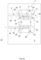
- Fig. 3a and Fig. 3b are schematic diagram of an air conditioner 2 according to a second embodiment of the disclosure.
- Fig. 3a shows the air conditioner 2 in a refrigerant loop cooling mode
- Fig. 3b shows the air conditioner 2 in a ventilation cooling mode.
- the arrows indicate the direction of air flow through the air conditioner 2.
- the air conditioner 2 differs from the first embodiment as it further comprises a closing element 34, configured to be movable between a first position, in Fig. 3a , and a second position, in Fig. 3b , wherein at the first position the closing element 34 closes the first air path 6 and at the second position the closing element 34 opens the first air path 6.
- the closing element 34 is further configured to close the second air path 14 at the second position and open the second air path 14 at the first position. It is also possible that the first air path 6 and the second air path 14 are provided with separate closing elements.
- the first air path 6 and the second air path 14 overlap, such that the two air paths 6, 14 merge into one path, towards the cooling air outlet 44.
- the first air path 6 and the second air path 14 merge after the second heat exchanger 64, and before the fluid supply system 26.
- the first air path 6 and the second air path 14 may merge at different points, for example the overlap may exist across the length of the second heat exchanger 64.
- the merge may occur after at least part of the air supply system 26, i.e., it is possible for fans to be located both before and after the merging of the two paths.
- the air supply system 26 it is possible for the air supply system 26 to comprise a single fan.
- the single fan can supply air during the ventilation mode and the refrigerant cooling mode, with the closing element 34 used to control the flow of air through the two air paths 6, 14.
- Fig. 4a and Fig. 4b are detailed views of an air conditioner, such as the air conditioner 2 in Fig. 3a and 3b , comprising a first closing element 66 and a second closing element 68.
- Fig. 4a shows the first closing element 66 and the second closing element 68 at a first position
- Fig. 4b shows the first closing element 66 and the second closing element 68 at a second position.
- the second air path inlet 48 is open and the closing elements close the first tube opening 54
- the first tube opening 54 is open and the closing elements 66, 68 close the second air path inlet 48.
- the second air path inlet 48 is formed as two openings, either side of the first tube opening 54.
- the first closing element 66 and the second closing element 68 are configured such that they connect with one another to close the first tube opening 54 at the first position.
- the first closing element 66 and the second closing element 68 may connect by contacting one another.
- the first closing element 66 and the second closing element 68 may connect via mutual contact of an element located in the first tube opening 54.
- the first closing element 66 and the second closing element 68 are configured to overlap.
- the first closing element 66 and/or the second closing element 68 may comprise a sealing element (not shown), wherein the sealing element may be integrally formed, or may comprises a separate sealing element attached by any known joining means.
- the first closing element 66 and the second closing element 68 may be configured to abut at the first position, such that they close the first tube opening 54 without overlapping.
- the first closing element 66 and the second closing element 68 are configured to form a gap.
- the first closing element 66 and the second closing element 68 have a rectangular shape, and the gap formed has a rectangular shape.
- the first closing element 66 and the second closing element 68 and the gap formed there between may have any shape, as long as the second air path inlet 48 and the first tube opening 54 can be opened and closed as described.
- Fig. 5 is a schematic diagram of an air conditioner 2.
- the air conditioner 2 configured to be located in an indoor space 4.
- the air conditioner 2 comprises a first air path 6, comprising a first air path inlet portion (8) which is configured to interface with an outdoor space 10, and a first air path outlet portion (12) configured to interface with the indoor space 4.
- the air conditioner 2 further comprises a second air path 14, comprising a second air path inlet portion 16 configured to interface with the indoor space 4, and a second air path outlet portion 18 configured to interface with the indoor space 4.
- the air conditioner 2 further comprises a third air path 20, comprising a third air path inlet portion 22 configured to interface with the indoor space 4, and a third air path outlet portion 24 configured to interface with the outdoor space 10.
- the third air path 20 is distinct from the first air path 6 and the second air path 14.
- the air conditioner 2 further comprises a refrigerant loop 30, configured to extract heat from the second air path (14), and to expel heat to the third air path 20.
- the air conditioner 2 further comprises a compressor 32, configured to pump a refrigerant around the refrigerant loop 30.
- the air conditioner 2 further comprises an air supply system 26, configured to supply cooled air to the indoor space 4 via the second air path 16 and to supply air from the outdoor space 10 via the first air path 6.
- the air conditioner 2 further comprises an air removal system 28, configured to remove air from the indoor space 4 via the third air path 20 to the outdoor space 10.
Landscapes
- Engineering & Computer Science (AREA)
- Chemical & Material Sciences (AREA)
- Combustion & Propulsion (AREA)
- Mechanical Engineering (AREA)
- General Engineering & Computer Science (AREA)
- Life Sciences & Earth Sciences (AREA)
- Sustainable Energy (AREA)
- Sustainable Development (AREA)
- Air Conditioning Control Device (AREA)
Priority Applications (1)
| Application Number | Priority Date | Filing Date | Title |
|---|---|---|---|
| EP23195998.2A EP4521032A1 (de) | 2023-09-07 | 2023-09-07 | Klimaanlage mit konfiguration zur anordnung in einem innenraum |
Applications Claiming Priority (1)
| Application Number | Priority Date | Filing Date | Title |
|---|---|---|---|
| EP23195998.2A EP4521032A1 (de) | 2023-09-07 | 2023-09-07 | Klimaanlage mit konfiguration zur anordnung in einem innenraum |
Publications (1)
| Publication Number | Publication Date |
|---|---|
| EP4521032A1 true EP4521032A1 (de) | 2025-03-12 |
Family
ID=88017668
Family Applications (1)
| Application Number | Title | Priority Date | Filing Date |
|---|---|---|---|
| EP23195998.2A Pending EP4521032A1 (de) | 2023-09-07 | 2023-09-07 | Klimaanlage mit konfiguration zur anordnung in einem innenraum |
Country Status (1)
| Country | Link |
|---|---|
| EP (1) | EP4521032A1 (de) |
Citations (6)
| Publication number | Priority date | Publication date | Assignee | Title |
|---|---|---|---|---|
| EP0055000A1 (de) * | 1980-12-19 | 1982-06-30 | Philips Patentverwaltung GmbH | Vorrichtung zum Belüften und Heizen von Innenräumen |
| US20040045304A1 (en) * | 2001-11-30 | 2004-03-11 | Choon-Kyoung Park | Air conditioning apparatus |
| EP2306107A1 (de) * | 2009-09-24 | 2011-04-06 | Eiffage Construction | System und Verfahren zur Be- und Entlüftung für die Heißwasserbereitung für den Haushalt und zur Kompaktheizung mit integrierter Wärmepumpe |
| GB2572830A (en) * | 2018-04-03 | 2019-10-16 | Airsys Refrigeration Engineering Tech Beijing Co Ltd | Air conditioning unit |
| US20210108805A1 (en) * | 2018-04-02 | 2021-04-15 | Mitsubishi Electric Corporation | Air conditioner ventilation device and air conditioner ventilation method |
| EP3599430B1 (de) * | 2018-07-27 | 2021-09-15 | Muller Et Cie | Monoblock-gerät zur klimatisierung und lufterneuerung in einem raum, der sich in einem gebäude befindet |
-
2023
- 2023-09-07 EP EP23195998.2A patent/EP4521032A1/de active Pending
Patent Citations (6)
| Publication number | Priority date | Publication date | Assignee | Title |
|---|---|---|---|---|
| EP0055000A1 (de) * | 1980-12-19 | 1982-06-30 | Philips Patentverwaltung GmbH | Vorrichtung zum Belüften und Heizen von Innenräumen |
| US20040045304A1 (en) * | 2001-11-30 | 2004-03-11 | Choon-Kyoung Park | Air conditioning apparatus |
| EP2306107A1 (de) * | 2009-09-24 | 2011-04-06 | Eiffage Construction | System und Verfahren zur Be- und Entlüftung für die Heißwasserbereitung für den Haushalt und zur Kompaktheizung mit integrierter Wärmepumpe |
| US20210108805A1 (en) * | 2018-04-02 | 2021-04-15 | Mitsubishi Electric Corporation | Air conditioner ventilation device and air conditioner ventilation method |
| GB2572830A (en) * | 2018-04-03 | 2019-10-16 | Airsys Refrigeration Engineering Tech Beijing Co Ltd | Air conditioning unit |
| EP3599430B1 (de) * | 2018-07-27 | 2021-09-15 | Muller Et Cie | Monoblock-gerät zur klimatisierung und lufterneuerung in einem raum, der sich in einem gebäude befindet |
Similar Documents
| Publication | Publication Date | Title |
|---|---|---|
| US6612365B1 (en) | Heating-element accommodating-box cooling apparatus and method of controlling the same | |
| US8939826B2 (en) | HVAC apparatus with HRV/ERV unit and vertical fan coil unit | |
| US7987680B2 (en) | Air conditioner | |
| EP4036486B1 (de) | Integriertes hlk-system für ein gebäude | |
| CN107943162B (zh) | 模块化环境控制室 | |
| KR101713546B1 (ko) | 일체형 환기 및 냉난방시스템 및 이를 이용한 환기 및 냉난방방법 | |
| BRPI0710582A2 (pt) | sistema de condicionamento de ar de capacidade variável | |
| US11073301B2 (en) | Heat pump with integrated energy recovery ventilator (ERV) | |
| US10415848B2 (en) | Systems and methods for pivotable evaporator coils | |
| CA2746405A1 (en) | Hvac apparatus with hrv/erv unit and vertical fan coil unit | |
| US12117191B2 (en) | Climate control system with improved leak detector | |
| US20180372361A1 (en) | Heat exchange type ventilation device | |
| US9377248B2 (en) | Integrated accumulator and receiver having a vibration damping guide tube | |
| EP4521032A1 (de) | Klimaanlage mit konfiguration zur anordnung in einem innenraum | |
| US9671131B2 (en) | Hydronic air heater | |
| CN109579140B (zh) | 一种空调器室内机组、空调器及其制冷控制方法 | |
| US20230228122A1 (en) | Systems and methods for electronically locking hvac doors | |
| US11204192B2 (en) | Adjustable duct for HVAC system | |
| GB2381855A (en) | Self contained air conditioning unit | |
| KR20150096308A (ko) | 공기 조화기의 실외 유닛 | |
| US20180094429A1 (en) | Systems for insulating panels in heating, ventilating, and air conditioning applications | |
| US20080245521A1 (en) | Cooling system for an enclosure | |
| EP2017538A2 (de) | Klimaanlagensystem für ein Wohnhaus | |
| JP2012117755A (ja) | 空気調和機 | |
| JPH11248232A (ja) | 床暖房空調システム |
Legal Events
| Date | Code | Title | Description |
|---|---|---|---|
| PUAI | Public reference made under article 153(3) epc to a published international application that has entered the european phase |
Free format text: ORIGINAL CODE: 0009012 |
|
| STAA | Information on the status of an ep patent application or granted ep patent |
Free format text: STATUS: THE APPLICATION HAS BEEN PUBLISHED |
|
| AK | Designated contracting states |
Kind code of ref document: A1 Designated state(s): AL AT BE BG CH CY CZ DE DK EE ES FI FR GB GR HR HU IE IS IT LI LT LU LV MC ME MK MT NL NO PL PT RO RS SE SI SK SM TR |
|
| STAA | Information on the status of an ep patent application or granted ep patent |
Free format text: STATUS: REQUEST FOR EXAMINATION WAS MADE |
|
| 17P | Request for examination filed |
Effective date: 20250904 |